JP2012196067A - Battery charge-discharge system and energy management system - Google Patents
Battery charge-discharge system and energy management system Download PDFInfo
- Publication number
- JP2012196067A JP2012196067A JP2011058692A JP2011058692A JP2012196067A JP 2012196067 A JP2012196067 A JP 2012196067A JP 2011058692 A JP2011058692 A JP 2011058692A JP 2011058692 A JP2011058692 A JP 2011058692A JP 2012196067 A JP2012196067 A JP 2012196067A
- Authority
- JP
- Japan
- Prior art keywords
- charge
- discharge
- vehicle
- controllers
- battery
- Prior art date
- Legal status (The legal status is an assumption and is not a legal conclusion. Google has not performed a legal analysis and makes no representation as to the accuracy of the status listed.)
- Granted
Links
- 238000004891 communication Methods 0.000 claims abstract description 49
- 230000005856 abnormality Effects 0.000 claims abstract description 35
- 230000002159 abnormal effect Effects 0.000 claims description 23
- 238000001514 detection method Methods 0.000 claims description 22
- 238000007599 discharging Methods 0.000 claims description 14
- 238000004364 calculation method Methods 0.000 claims description 8
- 238000012544 monitoring process Methods 0.000 claims 4
- 238000010248 power generation Methods 0.000 description 7
- 238000007726 management method Methods 0.000 description 6
- 238000010586 diagram Methods 0.000 description 4
- 230000005611 electricity Effects 0.000 description 4
- 238000004519 manufacturing process Methods 0.000 description 3
- 238000000034 method Methods 0.000 description 3
- 208000037309 Hypomyelination of early myelinating structures Diseases 0.000 description 1
- 241000150258 Prospect Hill orthohantavirus Species 0.000 description 1
- 238000004378 air conditioning Methods 0.000 description 1
- 230000005540 biological transmission Effects 0.000 description 1
- 229920000218 poly(hydroxyvalerate) Polymers 0.000 description 1
Images

Classifications
-
- Y—GENERAL TAGGING OF NEW TECHNOLOGICAL DEVELOPMENTS; GENERAL TAGGING OF CROSS-SECTIONAL TECHNOLOGIES SPANNING OVER SEVERAL SECTIONS OF THE IPC; TECHNICAL SUBJECTS COVERED BY FORMER USPC CROSS-REFERENCE ART COLLECTIONS [XRACs] AND DIGESTS
- Y02—TECHNOLOGIES OR APPLICATIONS FOR MITIGATION OR ADAPTATION AGAINST CLIMATE CHANGE
- Y02E—REDUCTION OF GREENHOUSE GAS [GHG] EMISSIONS, RELATED TO ENERGY GENERATION, TRANSMISSION OR DISTRIBUTION
- Y02E60/00—Enabling technologies; Technologies with a potential or indirect contribution to GHG emissions mitigation
- Y02E60/10—Energy storage using batteries
-
- Y—GENERAL TAGGING OF NEW TECHNOLOGICAL DEVELOPMENTS; GENERAL TAGGING OF CROSS-SECTIONAL TECHNOLOGIES SPANNING OVER SEVERAL SECTIONS OF THE IPC; TECHNICAL SUBJECTS COVERED BY FORMER USPC CROSS-REFERENCE ART COLLECTIONS [XRACs] AND DIGESTS
- Y02—TECHNOLOGIES OR APPLICATIONS FOR MITIGATION OR ADAPTATION AGAINST CLIMATE CHANGE
- Y02P—CLIMATE CHANGE MITIGATION TECHNOLOGIES IN THE PRODUCTION OR PROCESSING OF GOODS
- Y02P90/00—Enabling technologies with a potential contribution to greenhouse gas [GHG] emissions mitigation
- Y02P90/60—Electric or hybrid propulsion means for production processes
-
- Y—GENERAL TAGGING OF NEW TECHNOLOGICAL DEVELOPMENTS; GENERAL TAGGING OF CROSS-SECTIONAL TECHNOLOGIES SPANNING OVER SEVERAL SECTIONS OF THE IPC; TECHNICAL SUBJECTS COVERED BY FORMER USPC CROSS-REFERENCE ART COLLECTIONS [XRACs] AND DIGESTS
- Y02—TECHNOLOGIES OR APPLICATIONS FOR MITIGATION OR ADAPTATION AGAINST CLIMATE CHANGE
- Y02T—CLIMATE CHANGE MITIGATION TECHNOLOGIES RELATED TO TRANSPORTATION
- Y02T10/00—Road transport of goods or passengers
- Y02T10/60—Other road transportation technologies with climate change mitigation effect
- Y02T10/70—Energy storage systems for electromobility, e.g. batteries
-
- Y—GENERAL TAGGING OF NEW TECHNOLOGICAL DEVELOPMENTS; GENERAL TAGGING OF CROSS-SECTIONAL TECHNOLOGIES SPANNING OVER SEVERAL SECTIONS OF THE IPC; TECHNICAL SUBJECTS COVERED BY FORMER USPC CROSS-REFERENCE ART COLLECTIONS [XRACs] AND DIGESTS
- Y02—TECHNOLOGIES OR APPLICATIONS FOR MITIGATION OR ADAPTATION AGAINST CLIMATE CHANGE
- Y02T—CLIMATE CHANGE MITIGATION TECHNOLOGIES RELATED TO TRANSPORTATION
- Y02T90/00—Enabling technologies or technologies with a potential or indirect contribution to GHG emissions mitigation
- Y02T90/10—Technologies relating to charging of electric vehicles
- Y02T90/16—Information or communication technologies improving the operation of electric vehicles
- Y02T90/167—Systems integrating technologies related to power network operation and communication or information technologies for supporting the interoperability of electric or hybrid vehicles, i.e. smartgrids as interface for battery charging of electric vehicles [EV] or hybrid vehicles [HEV]
-
- Y—GENERAL TAGGING OF NEW TECHNOLOGICAL DEVELOPMENTS; GENERAL TAGGING OF CROSS-SECTIONAL TECHNOLOGIES SPANNING OVER SEVERAL SECTIONS OF THE IPC; TECHNICAL SUBJECTS COVERED BY FORMER USPC CROSS-REFERENCE ART COLLECTIONS [XRACs] AND DIGESTS
- Y04—INFORMATION OR COMMUNICATION TECHNOLOGIES HAVING AN IMPACT ON OTHER TECHNOLOGY AREAS
- Y04S—SYSTEMS INTEGRATING TECHNOLOGIES RELATED TO POWER NETWORK OPERATION, COMMUNICATION OR INFORMATION TECHNOLOGIES FOR IMPROVING THE ELECTRICAL POWER GENERATION, TRANSMISSION, DISTRIBUTION, MANAGEMENT OR USAGE, i.e. SMART GRIDS
- Y04S30/00—Systems supporting specific end-user applications in the sector of transportation
- Y04S30/10—Systems supporting the interoperability of electric or hybrid vehicles
- Y04S30/12—Remote or cooperative charging
Abstract
Description
本発明は、電動車両のバッテリの充放電システムに関するものであり、特に、複数の電動車両のバッテリの充放電を管理するエネルギーマネジメントシステムに関するものである。 The present invention relates to a charge / discharge system for a battery of an electric vehicle, and more particularly, to an energy management system for managing charge / discharge of a battery of a plurality of electric vehicles.
電力網に電力の需要・供給の自動制御手段を組み込んだ「スマートグリッド」と呼ばれる次世代電力網の開発が、近年注目を浴びている。スマートグリッドでは、電力網における電力の流れを供給側だけでなく需要側からも制御することによって、電力の需要と供給の最適化が図られる。 In recent years, the development of a next-generation power network called “smart grid” that incorporates automatic control of power supply and demand in the power network has attracted attention. In the smart grid, power demand and supply can be optimized by controlling the flow of power in the power network not only from the supply side but also from the demand side.
例えば各家庭が所有する電動車両(例えば電気自動車(Electric Vehicle;EV)やプラグインハイブリッド車(Plug-in Hybrid Vehicle;PHV))のバッテリ(蓄電池)は、電力需要のピークを低減して平滑化を図るためのバッファとして利用できる。すなわち電力需要の少ない時間帯に充電した電動車両のバッテリの電力を、電力需要のピーク時に住宅で使用することによって、電力需要のピークが低減される。一般に、深夜などの電力需要の少ない時間帯は電気料金が安く設定されているため、各家庭の電気料金の節約にもつながる。スマートグリッドは、このような電力の流れの制御を自動的に行おうとするものである。 For example, batteries (storage batteries) of electric vehicles owned by households (for example, electric vehicles (EV) and plug-in hybrid vehicles (PHV)) are smoothed by reducing the peak of power demand. It can be used as a buffer for That is, the power demand peak is reduced by using the electric power of the battery of the electric vehicle charged in the time zone when the power demand is small at the time of the peak power demand. In general, since electricity charges are set cheaply at times such as midnight when electricity demand is low, the electricity charges of each household can be saved. The smart grid automatically controls such a power flow.
スマートグリッドにおける電力の流れは、各需要家に配備されるエネルギーマネジメントシステム(Energy Management System;EMS)によって管理される。EMSは需要家の発電設備や、負荷設備、蓄電設備などを管理下に置き、電力需要が平滑化されるようにそれらを制御して、電力会社からの電力購入量を削減するように働く。 The flow of electric power in the smart grid is managed by an energy management system (EMS) installed in each consumer. EMS puts power generation facilities, load facilities, power storage facilities, and the like of customers under control, and controls them so that power demand is smoothed, thereby reducing the amount of power purchased from the power company.
またスマートグリッドの仕組みは、一般家庭だけでなく、工場やビルなどの大規模需要家での活用も期待されている(例えば特許文献1、非特許文献1)。例えば工場用のEMS(Factory Energy Management System;FEMS)は、工場内にある生産設備のエネルギー量の変化を、その生産量に着目して定量的に分析することにより、工場の電力需給の最適化を図ることができる。
The smart grid mechanism is expected to be used not only by ordinary households but also by large-scale consumers such as factories and buildings (for example,
工場やビルといった大規模需要家においても、家庭の場合と同様に、電動車両のバッテリを蓄電デバイス(バッファ)として活用できる。特に工場では、従業員の通勤車両をはじめ多くの車両が出入りするため、複数の電動車両のバッテリを組み合わせて大容量の蓄電デバイスとして使用することも期待できる。そのためには、工場にバッテリの充放電を行う充放電コントローラを複数個配備し、FEMSがそれら複数個の充放電コントローラを統括して監視・制御する必要がある。 Even in a large-scale consumer such as a factory or a building, the battery of the electric vehicle can be used as a power storage device (buffer) as in the case of a home. In particular, in factories, since many vehicles such as employee commuting vehicles come and go, it can be expected that batteries of a plurality of electric vehicles are combined to be used as a large-capacity electricity storage device. For this purpose, it is necessary to install a plurality of charge / discharge controllers for charging / discharging the battery in the factory, and the FEMS must monitor and control the plurality of charge / discharge controllers.
例えば、工場内にFEMSで監視・制御された複数の充放電コントローラを配備し、その各々に従業員の通勤車両が接続する形態のシステムが考えられる。このシステムでは従業員の勤務時間中に、各車両のバッテリを工場の蓄電デバイスとして利用できる。その間、各車両のバッテリの充放電がFEMSの管理下で行われる。一方、各車両は従業員の帰宅にも使用されるため、FEMSは、勤務時間が終わるときには各車両のバッテリ残量を従業員が帰宅できる電力量以上に確保する必要がある。 For example, a system in which a plurality of charge / discharge controllers monitored and controlled by FEMS are arranged in a factory, and an employee's commuting vehicle is connected to each of them is conceivable. In this system, the battery of each vehicle can be used as a power storage device in a factory during the working hours of employees. Meanwhile, charging / discharging of the battery of each vehicle is performed under the control of FEMS. On the other hand, since each vehicle is also used for returning to the employee, the FEMS needs to ensure that the remaining battery level of each vehicle exceeds the amount of electric power that the employee can return to when the working hours are over.
しかし、何らかの理由により一部の充放電コントローラが故障して正常にバッテリの充放電を行えなくなることも考えられる。例えばFEMSの制御によりバッテリから工場へ電力を供給した後に充放電コントローラの故障が生じた場合には、それに接続している車両は、帰宅に充分なだけのバッテリ残量が確保されていない可能性があり、その車両のユーザが帰宅できないといった事態が生じ得る。 However, it is also conceivable that some charge / discharge controllers fail for some reason and the battery cannot be charged / discharged normally. For example, when a failure occurs in the charge / discharge controller after power is supplied from the battery to the factory under the control of the FEMS, there is a possibility that the vehicle connected to the controller does not have enough battery power to return home. There is a possibility that the user of the vehicle cannot go home.
本発明は以上のような課題を解決するためになされたものであり、電動車両のバッテリの充放電を行うコントローラを複数個含む充放電システムにおいて、一部のコントローラが故障したとき、各コントローラに接続した車両を適切に誘導して、故障したコントローラに接続していた車両の救済を図ることを目的とする。 The present invention has been made to solve the above problems, and in a charge / discharge system including a plurality of controllers for charging / discharging a battery of an electric vehicle, when some of the controllers fail, each controller is An object is to appropriately guide the connected vehicle and to rescue the vehicle connected to the failed controller.
本発明に係るバッテリ充放電システムは、電動車両のバッテリの充放電を行う複数の充放電コントローラと、前記複数の充放電コントローラを監視・制御するEMS(エネルギーマネジメントシステム)と、前記複数の充放電コントローラに接続される車両およびそのユーザの通信アドレスを関連付けて記憶した記憶装置と、前記EMSが各前記ユーザの通信アドレスへ所定の通知を送信するための通信サーバとを備え、前記EMSは、前記複数の充放電コントローラにおける異常の有無および接続した車両を監視し、前記複数の充放電コントローラの一部の異常が検出された場合、異常のある充放電コントローラに接続した車両のユーザの通信アドレスに、使用中でない正常な充放電コントローラへの移動を促す通知を送信するものである。 A battery charge / discharge system according to the present invention includes a plurality of charge / discharge controllers that charge / discharge a battery of an electric vehicle, an EMS (energy management system) that monitors and controls the plurality of charge / discharge controllers, and the plurality of charge / discharges. A storage device that associates and stores a vehicle connected to a controller and a communication address of the user, and a communication server for the EMS to transmit a predetermined notification to the communication address of each user, the EMS The presence / absence of abnormality in the plurality of charge / discharge controllers and the connected vehicle are monitored, and when some abnormality of the plurality of charge / discharge controllers is detected, the communication address of the user of the vehicle connected to the abnormal charge / discharge controller is displayed. , Which sends a notification to move to a normal charge / discharge controller that is not in use
本発明によれば、複数の充放電コントローラの一部に異常が生じた場合に、それに接続していた車両を正常な充放電コントローラに誘導して救済する。従って、当該車両の充電不足を防止でき、ユーザの車両の使用に支障を来すことを防止できる。 According to the present invention, when an abnormality occurs in some of the plurality of charge / discharge controllers, the vehicle connected thereto is guided to the normal charge / discharge controller and rescued. Therefore, insufficient charging of the vehicle can be prevented, and the user's use of the vehicle can be prevented from being hindered.
<実施の形態1>
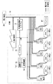
図1は、本発明の実施の形態に係る充放電システムの構成図である。同図において、各ブロック間の太線は電力線、細線は通信線を示している。
<
FIG. 1 is a configuration diagram of a charge / discharge system according to an embodiment of the present invention. In the figure, a thick line between blocks indicates a power line, and a thin line indicates a communication line.
工場10は、製造ラインの電動機器や照明や空調設備等の工場内負荷11、発電設備である太陽光発電システム12、バッテリの充放電を行う充放電コントローラCR1〜CR5、およびそれらの電力の流れを管理するFEMS13を備えている。また本実施の形態のFEMS13には、当該FEMS13が外部との通信を行うための通信サーバ15が接続され、通信サーバ15には所定の情報が格納される記憶装置14が接続されている。記憶装置14は、FEMS13あるいは通信サーバ15に内蔵されていてもよい。
The
工場10には、電力会社20からの電力が供給されている。FEMS13は、太陽光発電システム12が発電した電力や、充放電コントローラCR1〜CR5に接続されたバッテリに蓄積されている電力を工場内負荷11に供給したり、太陽光発電システム12で発電した余剰な電力や、電力会社20からの安価な深夜電力などを充放電コントローラCR1〜CR5に接続されたバッテリに蓄積したりして、工場10の電力需要の平滑化を図り、電力会社20からの購入電力を削減するように働く。
The
FEMS13は、工場内負荷11、太陽光発電システム12、充放電コントローラCR1〜CR5との通信が可能であり、それらの動作の監視・制御を行っている。図1ではその通信を、専用の通信線を用いたLAN(Local Area Network)通信として示しているが、例えば電力線を通信線として用いるPLC(Power Line Communications)等を用いてもよい。
The FEMS 13 can communicate with the in-factory load 11, the photovoltaic
また充放電コントローラCR1〜CR5は、それに接続された機器(例えばEV、PHV等の車両やバッテリユニット)との通信機能を有している。EVやPHVなどの車両が接続された場合には、充放電コントローラCR1〜CR5はその車両からバッテリの充放電に関する情報(バッテリ残量等)の他、車載のカーナビゲーションシステムから走行履歴や走行計画等を取得することも可能である。FEMS13は、充放電コントローラCR1〜CR5を通してこれらの情報を得ることができ、その情報に基づいて各車両のバッテリの充放電を制御する。 In addition, the charge / discharge controllers CR1 to CR5 have a communication function with devices (for example, vehicles such as EVs and PHVs and battery units) connected thereto. When a vehicle such as an EV or a PHV is connected, the charge / discharge controllers CR1 to CR5 receive information on the charge / discharge of the battery (battery remaining amount, etc.) from the vehicle, as well as the travel history and travel plan from the in-vehicle car navigation system. Etc. can also be obtained. The FEMS 13 can obtain these pieces of information through the charge / discharge controllers CR1 to CR5, and controls charge / discharge of the battery of each vehicle based on the information.
充放電コントローラCR1〜CR5と、それに接続された機器との間の通信方式も任意でよい。例えば充電コントローラと機器との接続ケーブル内の通信線を用いるLAN通信やCAN(Controller Area Network)通信、接続ケーブル内の電力線を通信線として用いるPLC、あるいは近距離の無線通信であってもよい。 The communication method between the charge / discharge controllers CR1 to CR5 and the devices connected thereto may be arbitrary. For example, LAN communication or CAN (Controller Area Network) communication using a communication line in a connection cable between a charge controller and a device, PLC using a power line in the connection cable as a communication line, or short-range wireless communication may be used.
ここで、図1に示す充放電コントローラCR1〜CR5のうち、CR1〜CR4は、工場10の従業員の通勤車両のバッテリの充放電を行う目的で駐車場に配備されたものであり、CR5は専ら工場10に備え付けのバッテリBTの充放電するものと仮定する。つまり充放電コントローラCR1〜CR4は、従業員の勤務時間のみに車両が接続されるが、充放電コントローラCR5には常にバッテリBTが接続される。
Here, among the charge / discharge controllers CR1 to CR5 shown in FIG. 1, CR1 to CR4 are deployed in the parking lot for the purpose of charging and discharging the battery of the commuter vehicle of the employee of the
本発明は、車両が接続される充放電コントローラに異常(故障)が発生したときの対策を講じるものであるので、以下の説明では、常にバッテリBTが接続する充放電コントローラCR5は説明の対象から除外する。 Since the present invention takes measures when an abnormality (failure) occurs in the charge / discharge controller to which the vehicle is connected, in the following description, the charge / discharge controller CR5 to which the battery BT is always connected will be described. exclude.
本実施の形態では、充放電コントローラCR1〜CR4に、工場10の従業員が通勤で用いる車両EV1〜EV4のいずれかが接続されるものとする。図1では、充放電コントローラCR1,CR2,CR3,CR4に、それぞれ車両EV1,EV2,EV3,EV4が接続されているが、どの充放電コントローラにどの車両が接続しても構わない。また車両EV1,EV2,EV3,EV4のユーザ(従業員)をそれぞれユーザU1,U2,U3,U4と定義する。
In the present embodiment, any of the vehicles EV1 to EV4 used by the employees of the
FEMS13は、ユーザU1〜U4の勤務時間中に、車両EV1〜EV4のバッテリを蓄電デバイスとして利用でき、その間車両EV1〜EV4のバッテリの充放電は、FEMS13の管理下で行われる。またFEMS13は、ユーザU1〜U4の勤務時間が終わる時刻(退社時)に、車両EV1〜EV4の各バッテリ残量を、ユーザU1〜U4が退社時に必要とするバッテリ残量(必要バッテリ残量)以上にする。 The FEMS 13 can use the batteries of the vehicles EV1 to EV4 as power storage devices during the working hours of the users U1 to U4, and during that time, charging and discharging of the batteries of the vehicles EV1 to EV4 are performed under the control of the FEMS13. Further, the FEMS 13 determines the remaining battery levels of the vehicles EV1 to EV4 at the time when the work hours of the users U1 to U4 end (when leaving the office), and the remaining battery levels (required remaining battery capacity) required by the users U1 to U4 when leaving the office. That's it.
充放電コントローラCR1〜CR4は、それぞれ自己に接続した車両を車台番号などの識別子(ID)から識別することが可能である。また記憶装置14には、車両EV1〜EV4のIDおよび必要バッテリ残量の情報が、そのユーザU1〜U4のID(社員番号など)と関連付けされて登録されている。FEMS13は、これらの情報に基づいて充放電コントローラCR1〜CR4を制御することにより、車両EV1〜EV4の必要バッテリ残量を確保することができる。
Each of the charge / discharge controllers CR1 to CR4 can identify a vehicle connected to itself from an identifier (ID) such as a chassis number. In the
必要バッテリ残量の例としては、工場10からユーザU1〜U4それぞれの自宅までの走行に必要な電力量とするのが典型的であろう。また必要バッテリ残量は、電力量[kWh]でもよいし、バッテリの容量に対する割合[%]でもよい。
As an example of the necessary battery remaining amount, it is typical that the amount of power required for traveling from the
さらに、本実施の形態では、記憶装置14にユーザU1〜U4の通信アドレス(メールアドレスやIPアドレス、電話番号など)も、ユーザU1〜U4のIDに関連付けて登録されている。ユーザU1〜U4の通信アドレスは、FEMS13が通信サーバ15を通して所定の通知を送信できるものであり、ユーザU1〜U4が所持する携帯型端末(携帯電話やPDA(Personal Digital Assistant))のアドレスであることが望ましい。
Further, in the present embodiment, the communication addresses (email addresses, IP addresses, telephone numbers, etc.) of the users U1 to U4 are also registered in the
なお、記憶装置14の各登録内容は、充放電コントローラCR1〜CR4あるいは通信サーバ15を通した通信により、ユーザU1〜U4が変更することも可能である。
The registered contents of the
本実施の形態に係るFEMS13は、充放電コントローラCR1〜CR4の異常(故障)が発生して正常な充放電が行われなくなった場合に、異常のある充放電コントローラに接続した車両を、正常で他の車両が接続していない放電コントローラへ誘導する車両誘導手段を備えている。 FEMS13 which concerns on this Embodiment is normal, when the abnormality (failure) of charging / discharging controller CR1-CR4 generate | occur | produces and the normal charging / discharging controller is no longer performed, the vehicle connected to the charging / discharging controller with abnormality is normal. Vehicle guidance means for guiding to a discharge controller not connected to another vehicle is provided.
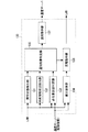
図2は、FEMS13が有する車両誘導手段の機能ブロック図である。通常、FEMS13はコンピュータであるため、車両誘導手段はプログラム、その各ブロックは当該プログラムのサブルーチンにより実現可能である。
FIG. 2 is a functional block diagram of vehicle guidance means included in the
図2の如く、車両誘導手段130は、異常状態検出部131、車両接続状況検出部132、必要量到達判定部133、差分演算部134、通知対象判定部135、充電指示部136および通知指示部137から構成されている。
As shown in FIG. 2, the
異常状態検出部131は、LANを通した充放電コントローラCR1〜CR4との通信により、充放電コントローラCR1〜CR4の異常の有無を監視する。充放電コントローラCR1〜CR4のそれぞれは、電流計や電圧計等の測定器を内蔵しており、それを用いて自己の充放電動作が正常に行われているか否かを判定できる。例えば、充放電コントローラCR1〜CR4が異常発生時にエラー信号を送信し、異常状態検出部131がそれを検出する構成でもよいし、充放電コントローラCR1〜CR4が正常を示す信号を常に送信し、それが途切れたときに異常状態検出部131が異常発生を認識する構成でもよい。
The abnormal
あるいは異常状態検出部131が、充放電コントローラCR1〜CR4の測定器を監視して自ら異常を検出する構成であってもよい。また異常状態検出部131が検出する充放電コントローラCR1〜CR4の異常には、充放電動作の異常の他、通信異常も含めてもよい。
Or the structure which the abnormality
車両接続状況検出部132は、充放電コントローラCR1〜CR4との通信により、充放電コントローラCR1〜CR4の接続状況を監視する。すなわち充放電コントローラCR1〜CR4がそれぞれ使用中(接続中)か否か、どの車両や機器が接続されているのか、等を検出する。
The vehicle connection
必要量到達判定部133は、充放電コントローラCR1〜CR4との通信により、充放電コントローラCR1〜CR4に接続した各車両のバッテリ残量を取得すると共に、通信サーバ15を介して記憶装置14から、その各車両のバッテリ残量の必要量(必要バッテリ残量)を取得する。そして、両者を比較して各車両のバッテリ残量が必要量に達しているか否かを判定する。
The necessary amount
差分演算部134は、必要量到達判定部133と同様に充放電コントローラCR1〜CR4に接続した各車両の現在のバッテリ残量および必要バッテリ残量を取得し、両者の差分を計算する。そして算出した差分に基づいて、バッテリ残量が必要量に達していない車両のうち、どの車両のバッテリ残量が必要量に近いか(短時間で必要量に達するか)を判定する。
The
車両誘導手段130は、異常状態検出部131によって充放電コントローラCR1〜CR4のいずれかの異常が発生した場合に、所定の車両のユーザの通信アドレスに所定の通知を送信するが、通知対象判定部135は、その通知対象(送信先)およびその通知内容を、車両接続状況検出部132、必要量到達判定部133の出力結果に基づいて決定する。また通知指示部137は、通信サーバ15を制御して、通知対象判定部135が決定した通知内容を通知対象に送信する。
The
充放電コントローラCR1〜CR4のいずれかに異常が発生した場合、正常な充放電コントローラに空きがあれば、通知対象判定部135および通知指示部137は、異常のある充放電コントローラに接続した車両のユーザに、空いている正常な充放電コントローラへの移動を指示する通知(移動指示)を通知する。また正常な充放電コントローラの空きがなければ、正常な充放電コントローラに接続しバッテリ残量が必要量に達した車両のユーザに、その明け渡し(他の場所への移動)を指示する通知(明け渡し指示)を送信する。
If an abnormality occurs in any of the charge / discharge controllers CR1 to CR4, and there is a vacancy in the normal charge / discharge controller, the notification
しかし、正常な充放電コントローラの空きもなく、必要量に達した車両も存在しない場合もある。充電指示部136はその場合、差分演算部134の判定結果に基づき、正常な充放電コントローラに接続してバッテリ残量が必要量に比較的近い車両のバッテリを優先的に充電させる。その結果、必要バッテリ残量に達した車両ができれば、その車両のユーザは、明け渡し指示を送信する対象に含められる。
However, there are cases where there is no vacant normal charge / discharge controller and no vehicle has reached the required amount. In this case, based on the determination result of the
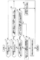
図3は、FEMS13が備える車両誘導手段130の動作を示すフローチャートである。以下、本実施の形態に係るバッテリ充放電システムの動作を、図3を参照しつつ説明する。
FIG. 3 is a flowchart showing the operation of the vehicle guidance means 130 provided in the
まず図4のように、充放電コントローラCR1,CR2,CR3にそれぞれ車両EV1,EV2,EV3が接続され、充放電コントローラCR4が空いている(使用されていない)状態を仮定する。この状態で、充放電コントローラCR1に異常が生じたとする(充放電コントローラCR2〜CR4は正常)。 First, as shown in FIG. 4, it is assumed that the vehicles EV1, EV2, EV3 are connected to the charge / discharge controllers CR1, CR2, CR3, respectively, and the charge / discharge controller CR4 is vacant (not used). Assume that an abnormality has occurred in the charge / discharge controller CR1 in this state (the charge / discharge controllers CR2 to CR4 are normal).
車両誘導手段130の異常状態検出部131により、充放電コントローラCR1の異常が検出されると(ステップS1においてYes)、車両接続状況検出部132は、正常な充放電コントローラCR2〜CR4に空きがあるか判定する(ステップS2)。ここでは充放電コントローラCR4が空いているので(ステップS2おいてYes)、充電指示部136は通知指示部137を介して通信サーバ15を制御し、異常のある充放電コントローラCR1に接続した車両EV1のユーザU1の通信アドレスに、車両EV1を充放電コントローラCR4への移動を指示する通知(移動指示)を送信する(ステップS3)。
When abnormality of charge / discharge controller CR1 is detected by abnormal
移動指示を受けたユーザU1は、車両EV1を充放電コントローラCR4に移動させ、充放電コントローラCR4に車両EV1を接続させる。それにより車両EV1は充放電コントローラCR1の異常から救済され、FEMS13の管理の下、正常にバッテリの充放電が実施される。よってユーザU1の退社時には、車両EV1が必要バッテリ残量に達することになり、車両EV1の充電不足によりユーザU1が帰宅できなくなるような事態は回避される。
Receiving the movement instruction, the user U1 moves the vehicle EV1 to the charge / discharge controller CR4 and connects the vehicle EV1 to the charge / discharge controller CR4. Thus, the vehicle EV1 is relieved from the abnormality of the charge / discharge controller CR1, and the battery is normally charged / discharged under the control of the
次に、図1に示したように、充放電コントローラCR1,CR2,CR3,CR4にそれぞれ車両EV1,EV2,EV3,EV4が接続しており、充放電コントローラCR1〜CR4に空きがない状態を仮定する。この状態で、充放電コントローラCR1に異常が生じたとする(充放電コントローラCR2〜CR4は正常)。 Next, as shown in FIG. 1, it is assumed that the vehicles EV1, EV2, EV3, EV4 are connected to the charge / discharge controllers CR1, CR2, CR3, and CR4, respectively, and the charge / discharge controllers CR1 to CR4 have no vacancy. To do. Assume that an abnormality has occurred in the charge / discharge controller CR1 in this state (the charge / discharge controllers CR2 to CR4 are normal).
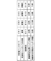
またここでは、図5の表に示すように、車両EV1〜EV4の必要バッテリ残量はいずれも8kWhであるとし、充放電コントローラCR1に異常が生じた時点で、車両EV1,EV2,EV3,EV4のバッテリ残量はそれぞれ3kWh、10kWh、5kWh、7kWhであったとする。また正常な充放電コントローラCR2〜CR4はいずれも車両EV2〜EV4のバッテリの放電を行っているものする。 Further, here, as shown in the table of FIG. 5, it is assumed that the necessary battery remaining amount of each of the vehicles EV1 to EV4 is 8 kWh, and the vehicles EV1, EV2, EV3, EV4 when the abnormality occurs in the charge / discharge controller CR1. Are assumed to be 3 kWh, 10 kWh, 5 kWh, and 7 kWh, respectively. In addition, the normal charge / discharge controllers CR2 to CR4 are assumed to discharge the batteries of the vehicles EV2 to EV4.
車両誘導手段130の異常状態検出部131により、充放電コントローラCR1の異常が検出されると(ステップS1においてYes)、車両接続状況検出部132により、充放電コントローラCR1〜CR4に空きがあるか否かが判定される(ステップS2)。ここでは充放電コントローラCR1〜CR4に空きがない(ステップS2おいてNo)。その場合、必要量到達判定部133は、正常な充放電コントローラCR2〜CR4に接続した車両EV2〜EV4の中に、必要バッテリ残量に達したものがあるか判定する(ステップS4)。
When abnormality of charge / discharge controller CR1 is detected by abnormal
ここでは図5のように、充放電コントローラCR2に接続した車両EV2が必要バッテリ残量に達している。つまり車両EV2の充放電がこの時点で中断しても、ユーザU2が帰宅時に困ることはない。そこで充電指示部136は、通知指示部137を介して通信サーバ15を制御し、ユーザU2へ、車両EV2を他の場所に移動させて充放電コントローラCR2を明け渡す指示の通知(明け渡し指示)を送信する。ただし、この明け渡し指示は、同じ車両のユーザに繰り返し送信されないように、必要バッテリ残量に達している車両のユーザのうち、未通知の者にのみ送信される(ステップS5,S6)。
Here, as shown in FIG. 5, the vehicle EV2 connected to the charge / discharge controller CR2 has reached the required remaining battery level. That is, even if charging / discharging of the vehicle EV2 is interrupted at this time, the user U2 is not in trouble when returning home. Accordingly, the charging
その後はステップS1に戻り、以上の動作が繰り返し行われるが、明け渡し指示を受けたユーザU2が車両EV2を移動させ、充放電コントローラCR2が空きになると(ステップS2おいてYes)、異常のある充放電コントローラCR1に接続した車両EV1のユーザU1の通信アドレスに、車両EV1を充放電コントローラCR2へ移動させる旨の移動指示が通知される(ステップS3)。移動指示を受けたユーザU1は、車両EV1を充放電コントローラCR2に移動させ、それに車両EV1を接続させることで救済され、車両EV1の充電不足を回避できる。 After that, the process returns to step S1 and the above operations are repeated. However, when the user U2 who has received the surrender instruction moves the vehicle EV2 and the charge / discharge controller CR2 becomes empty (Yes in step S2), the abnormal charging is performed. A movement instruction for moving the vehicle EV1 to the charge / discharge controller CR2 is notified to the communication address of the user U1 of the vehicle EV1 connected to the discharge controller CR1 (step S3). Receiving the movement instruction, the user U1 is rescued by moving the vehicle EV1 to the charge / discharge controller CR2 and connecting the vehicle EV1 to the vehicle EV1, thereby avoiding insufficient charging of the vehicle EV1.
しかし、明け渡し指示を通知してもユーザU2が車両EV2を移動させない場合(ステップS5においてYes)、または必要バッテリ量に達した車両がなかった場合(ステップS4においてNo)には、通知対象判定部135は明け渡し指示を通知できる対象を新たに作ろうとする。つまり必要バッテリ残量に達していない車両のバッテリを充電して必要バッテリ残量に到達させようとする。
However, if the user U2 does not move the vehicle EV2 (Yes in step S5) or no vehicle has reached the required battery amount (No in step S4) even if the delivery instruction is notified, the notification
この場合、差分演算部134は、正常な充放電コントローラに接続し且つ必要バッテリ残量に達していない各車両について、現在のバッテリ残量と必要バッテリ残量との差分を計算する。充電指示部136は、そのうち差分が最も小さいもの(最も早く必要バッテリ残量に到達できるもの)を優先的に充電の対象に決定し(ステップS7)、充放電コントローラを制御してその充電を行わせる(ステップS8)。
In this case, the
図5の例において車両EV2が明け渡し指示に応じなかった場合、車両EV3と車両EV4について、現在のバッテリ残量と必要バッテリ残量との差分を計算すると、車両EV3における差分は3kWh、車両EV4における差分は1kWhであるので、充電指示部136は車両EV4を充電の対象に決定する。充放電コントローラCR4は車両EV4のバッテリを放電中であったが、充電指示部136の制御により充電動作に切り替えられ、車両EV4のバッテリの充電が開始される。
In the example of FIG. 5, when the vehicle EV2 does not respond to the surrender instruction, the difference between the current battery remaining amount and the necessary battery remaining amount is calculated for the vehicle EV3 and the vehicle EV4, and the difference in the vehicle EV3 is 3 kWh. Since the difference is 1 kWh, the charging
その後はステップS1に戻るが、車両EV4が必要バッテリ残量に達すると、ユーザU4が明け渡し指示の送信対象となり(ステップS5においてNo)、ユーザU4へと明け渡し指示が送られる(ステップS6)。 Thereafter, the process returns to step S1, but when the vehicle EV4 reaches the required remaining battery level, the user U4 becomes a target for sending a surrender instruction (No in step S5), and a surrender instruction is sent to the user U4 (step S6).
そして明け渡し指示を受けたユーザU4が車両EV4を移動させ、充放電コントローラCR4が空きになると(ステップS2おいてYes)、異常のある充放電コントローラCR1に接続した車両EV1のユーザU1の通信アドレスに、車両EV1を充放電コントローラCR2へ移動させる旨の移動指示が通知される(ステップS3)。移動指示を受けたユーザU1は、車両EV1を充放電コントローラCR4に移動させ、それに車両EV1を接続させることで救済され、車両EV1の充電不足を回避できる。 When the user U4 who has received the surrender instruction moves the vehicle EV4 and the charge / discharge controller CR4 becomes empty (Yes in step S2), the communication address of the user U1 of the vehicle EV1 connected to the abnormal charge / discharge controller CR1 is set. Then, a movement instruction for moving the vehicle EV1 to the charge / discharge controller CR2 is notified (step S3). Receiving the movement instruction, the user U1 is rescued by moving the vehicle EV1 to the charge / discharge controller CR4 and connecting the vehicle EV1 to the vehicle EV1, thereby avoiding insufficient charging of the vehicle EV1.
以上のように本実施の形態によれば、複数の充放電コントローラの一部に異常が発生しても、異常のある充放電コントローラに接続していた車両を正常な充放電コントローラへと誘導して救済でき、その車両のバッテリの充電不足を回避できる。また正常な充放電コントローラに空きがなかった場合には、それに接続した車両のユーザに対し充放電コントローラの明け渡し指示を通知するが、その通知対象は必要バッテリ残量に達した車両のユーザに限定される。そのため明け渡し指示を受けた車両がバッテリの充電不足になることも回避できる。 As described above, according to the present embodiment, even if an abnormality occurs in some of the plurality of charge / discharge controllers, the vehicle connected to the abnormal charge / discharge controller is guided to the normal charge / discharge controller. Can be saved, and it is possible to avoid insufficient charging of the battery of the vehicle. In addition, when there is no vacancy in the normal charge / discharge controller, the user of the vehicle connected thereto is notified of the surrender instruction of the charge / discharge controller, but the notification target is limited to the vehicle user who has reached the required remaining battery level. Is done. Therefore, it is possible to avoid a vehicle that has received a surrender instruction from being insufficiently charged.
<実施の形態2>
実施の形態1では、明け渡し指示を受けたユーザがそれに応じなかった場合や、充放電コントローラの空きも、必要バッテリ量に達している車両もなかった場合、バッテリ残量が必要量に比較的近い車両を優先的に充電対象とし、明け渡し指示の通知対象を新たに作る構成となっている。しかし全ての車両のバッテリ残量が少ない場合も考えられ、その場合には、充電対象の車両が必要バッテリ残量に達するまで長時間かかってしまう。
<Embodiment 2>
In the first embodiment, when the user who receives the surrender instruction does not respond to it, or when there is no vacant charge / discharge controller and no vehicle has reached the required battery amount, the remaining battery level is relatively close to the required amount. The vehicle is preferentially charged, and a notification target for a surrender instruction is newly created. However, there may be a case where the battery level of all the vehicles is low. In this case, it takes a long time until the vehicle to be charged reaches the required battery level.
実施の形態1では各車両のユーザの勤務時間の違いを考慮していないが、例えば交代勤務や、宿直勤務が導入された工場では、ユーザごとに勤務時間が異なる。そのようなケースでは、次の使用時刻(退社時刻)までの時間が比較的長い車両のユーザ(つまりバッテリの充電を急ぐ必要のない車両のユーザ)に明け渡し指示を通知し、その車両のバッテリ充電を後回しにすることも有効である。 In the first embodiment, the difference in the working hours of the users of each vehicle is not taken into consideration, but the working hours are different for each user in a factory where shift work or overnight work is introduced, for example. In such a case, the user of the vehicle having a relatively long time until the next use time (leaving time) (that is, the user of the vehicle who does not have to rush to charge the battery) is notified of the surrendering instruction, and the battery charging of the vehicle is performed. It is also effective to postpone.
すなわち記憶装置14に、車両EV1〜EV4の使用予定も記憶させておき、車両誘導手段130の通知対象判定部135が、図3のステップS4〜S8に並行して、正常な充放電コントローラに接続され且つ次の使用時刻までの時間が比較的長い車両のユーザに、明け渡し指示を通知してもよい。
That is, the use schedule of the vehicles EV1 to EV4 is also stored in the
この明け渡し指示を受けたユーザが車両を移動させ、充放電コントローラの空きができれば、図3のステップS3で、異常が発生した充放電コントローラに接続した車両のユーザに、正常な充放電コントローラへの移動指示が送信され、その車両が救済される。 If the user who has received this surrender instruction moves the vehicle and the charge / discharge controller is free, in step S3 in FIG. 3, the user of the vehicle connected to the charge / discharge controller in which an abnormality has occurred is connected to the normal charge / discharge controller. A travel instruction is sent and the vehicle is rescued.
なお、この明け渡し指示に従って充放電コントローラから離れた車両(充電を後回しにした車両)は、必要バッテリ残量に達していない。よってその後は、車両誘導手段130が、充電を後回しにした車両の救済のために、図3の動作を引き続き実行することが好ましい。その場合、ステップS3での移動指示の通知先が、充電を後回しにした車両のユーザに変更される。
It should be noted that the vehicle that has left the charge / discharge controller according to this delivery instruction (the vehicle that has been charged later) has not reached the required remaining battery level. Therefore, after that, it is preferable that the
以上の説明では、EMSとして、FEMSを例にして説明したが、本発明は複数の充放電コントローラを監視・制御するEMSであれば適用可能であり、例えば家庭用のEMS(Home Energy Management System;HEMS)やビル用のEMS(Building Energy Management System;BEMS)等にも適用できる。 In the above description, the FEMS has been described as an example of the EMS. However, the present invention is applicable to any EMS that monitors and controls a plurality of charge / discharge controllers. For example, a home EMS (Home Energy Management System; It can also be applied to HEMS) and building EMS (Building Energy Management System; BEMS).
10 工場、11 工場内負荷、12 太陽光発電システム、13 FEMS、14 記憶装置、15 通信サーバ、BT バッテリ、CR1〜CR5 充放電コントローラ、130 車両誘導手段、131 異常状態検出部、132 車両接続状況検出部、133 必要量到達判定部、134 差分演算部。 10 factory, 11 factory load, 12 photovoltaic power generation system, 13 FEMS, 14 storage device, 15 communication server, BT battery, CR1 to CR5 charge / discharge controller, 130 vehicle guidance means, 131 abnormal state detection unit, 132 vehicle connection status Detection unit, 133 necessary amount arrival determination unit, 134 difference calculation unit.
Claims (8)
前記複数の充放電コントローラを監視・制御するEMS(エネルギーマネジメントシステム)と、
前記複数の充放電コントローラに接続される車両およびそのユーザの通信アドレスを関連付けて記憶した記憶装置と、
前記EMSが各前記ユーザの通信アドレスへ所定の通知を送信するための通信サーバとを備え、
前記EMSは、
前記複数の充放電コントローラにおける異常の有無および接続した車両を監視し、
前記複数の充放電コントローラの一部の異常が検出された場合、異常のある充放電コントローラに接続した車両のユーザの通信アドレスに、使用中でない正常な充放電コントローラへの移動を促す通知を送信する
ことを特徴とするバッテリ充放電システム。 A plurality of charge / discharge controllers for charging / discharging the battery of the electric vehicle;
EMS (energy management system) for monitoring and controlling the plurality of charge / discharge controllers;
A storage device that associates and stores a vehicle connected to the plurality of charge / discharge controllers and a communication address of the user;
The EMS comprises a communication server for transmitting a predetermined notification to the communication address of each user,
The EMS is
Monitoring the presence or absence of abnormality in the plurality of charge / discharge controllers and the connected vehicle;
When some abnormality of the plurality of charge / discharge controllers is detected, a notification that prompts the user to move to a normal charge / discharge controller that is not in use is transmitted to the communication address of the user of the vehicle connected to the abnormal charge / discharge controller A battery charge / discharge system.
前記記憶装置は、各前記車両のバッテリ残量の必要量をさらに記憶しており、
前記EMSは、
前記複数の充放電コントローラに接続した各車両のバッテリ残量をさらに監視し、
前記複数の充放電コントローラの一部の異常が検出され、使用中でない正常な充放電コントローラが存在しない場合、正常な充放電コントローラに接続しバッテリ残量が必要量に達した車両のユーザの通信アドレスに、充放電コントローラの明け渡しを促す通知を送信する
ことを特徴とするバッテリ充放電システム。 The battery charge / discharge system according to claim 1,
The storage device further stores a required amount of battery remaining for each vehicle,
The EMS is
Further monitoring the remaining battery power of each vehicle connected to the plurality of charge / discharge controllers,
When some abnormalities of the plurality of charge / discharge controllers are detected and there is no normal charge / discharge controller that is not in use, communication of a vehicle user who has connected to the normal charge / discharge controller and the remaining battery level has reached the required amount A battery charging / discharging system, wherein a notification prompting the surrender of a charge / discharge controller is transmitted to an address.
前記EMSは、
前記複数の充放電コントローラの一部の異常が検出され、使用中でない正常な充放電コントローラも、正常な充放電コントローラに接続しバッテリ残量が必要量に達した車両も存在しない場合、正常な充放電コントローラに接続しバッテリ残量が必要量に比較的近い車両のバッテリを優先的に充電させる
ことを特徴とするバッテリ充放電システム。 The battery charge / discharge system according to claim 2,
The EMS is
If there is no normal charge / discharge controller that is not in use and a normal charge / discharge controller is connected to the normal charge / discharge controller and the remaining battery level has reached the required amount, there is no abnormality. A battery charge / discharge system which is connected to a charge / discharge controller and preferentially charges a vehicle battery whose remaining battery capacity is relatively close to a required amount.
前記記憶装置は、各前記車両の使用予定をさらに記憶しており、
前記EMSは、
前記複数の充放電コントローラの一部の異常が検出され、使用中でない正常な充放電コントローラが存在しない場合、正常な充放電コントローラに接続し次の使用時刻までの時間が比較的長い車両のユーザに、充放電コントローラの明け渡しを促す通知を送信する
ことを特徴とするバッテリ充放電システム。 The battery charge / discharge system according to claim 1,
The storage device further stores a use schedule of each vehicle,
The EMS is
When some abnormality of the plurality of charge / discharge controllers is detected and there is no normal charge / discharge controller that is not in use, a vehicle user who is connected to the normal charge / discharge controller and takes a relatively long time until the next use time In addition, a battery charge / discharge system is characterized by transmitting a notification prompting the surrender of the charge / discharge controller.
前記複数の充放電コントローラの異常の有無を監視する異常状態検出部と、
前記複数の充放電コントローラに接続された車両を識別する車両接続状況検出部と、
前記複数の充放電コントローラに接続される車両およびそのユーザの通信アドレスを関連付けて記憶した記憶装置と、
各前記ユーザの通信アドレスへ所定の通知を送信する通知指示部とを備え、
前記異常状態検出部によって前記複数の充放電コントローラの一部の異常が検出された場合、前記通知指示部が、前記車両接続状況検出部の識別結果に基づき、異常のある充放電コントローラに接続した車両のユーザの通信アドレスに、使用中でない正常な充放電コントローラへの移動を促す通知を送信する
ことを特徴とするエネルギーマネジメントシステム。 An energy management system that monitors and controls a plurality of charge / discharge controllers that charge and discharge a battery of an electric vehicle,
An abnormal state detector for monitoring the presence or absence of an abnormality in the plurality of charge / discharge controllers;
A vehicle connection status detection unit for identifying a vehicle connected to the plurality of charge / discharge controllers;
A storage device that associates and stores a vehicle connected to the plurality of charge / discharge controllers and a communication address of the user;
A notification instruction unit that transmits a predetermined notification to the communication address of each user,
When some abnormality of the plurality of charge / discharge controllers is detected by the abnormal state detection unit, the notification instruction unit is connected to an abnormal charge / discharge controller based on the identification result of the vehicle connection state detection unit. The energy management system characterized by transmitting the notification which prompts the movement to the normal charge / discharge controller which is not in use to the communication address of the user of the vehicle.
前記記憶装置は、各前記車両のバッテリ残量の必要量をさらに記憶しており、
当該エネルギーマネジメントシステムは、
前記複数の充放電コントローラに接続した各車両のバッテリ残量が必要量に達しているか否かを判定する必要量到達判定部をさらに備え、
前記異常状態検出部によって前記複数の充放電コントローラの一部の異常が検出され、使用中でない正常な充放電コントローラが存在しない場合、前記通知指示部が、前記必要量到達判定部の判定結果に基づき、正常な充放電コントローラに接続しバッテリ残量が必要量に達した車両のユーザの通信アドレスに、充放電コントローラの明け渡しを促す通知を送信する
ことを特徴とするエネルギーマネジメントシステム。 An energy management system according to claim 5,
The storage device further stores a required amount of battery remaining for each vehicle,
The energy management system
A required amount arrival determination unit for determining whether or not the remaining battery capacity of each vehicle connected to the plurality of charge / discharge controllers has reached a required amount;
When the abnormal state detection unit detects some abnormality of the plurality of charge / discharge controllers and there is no normal charge / discharge controller that is not in use, the notification instruction unit displays the determination result of the necessary amount arrival determination unit. Based on this, the energy management system is characterized by transmitting a notification prompting the surrender of the charge / discharge controller to the communication address of the user of the vehicle connected to a normal charge / discharge controller and having a remaining battery level.
前記複数の充放電コントローラに接続した各車両のバッテリ残量と必要バッテリ残量との差分を算出する差分演算部と、
所定の充放電コントローラに接続した車両のバッテリの充電を指示する充電指示部とをさらに備え、
前記異常状態検出部によって前記複数の充放電コントローラの一部の異常が検出され、使用中でない正常な充放電コントローラも、正常な充放電コントローラに接続しバッテリ残量が必要量に達した車両も存在しない場合、前記充電指示部が、前記差分演算部の算出結果に基づき、正常な充放電コントローラに接続しバッテリ残量が必要量に比較的近い車両のバッテリを優先的に充電させる
ことを特徴とするエネルギーマネジメントシステム。 An energy management system according to claim 6,
A difference calculation unit for calculating a difference between a remaining battery level of each vehicle connected to the plurality of charge / discharge controllers and a required remaining battery level;
A charge instructing unit for instructing charging of a vehicle battery connected to a predetermined charge / discharge controller;
Some abnormalities of the plurality of charge / discharge controllers are detected by the abnormal state detection unit, and a normal charge / discharge controller that is not in use is connected to a normal charge / discharge controller, and a vehicle in which the remaining battery level reaches a required amount When not present, the charging instruction unit preferentially charges a battery of a vehicle that is connected to a normal charge / discharge controller and whose battery remaining amount is relatively close to a required amount based on a calculation result of the difference calculation unit. Energy management system.
前記記憶装置は、各前記車両の使用予定をさらに記憶しており、
前記異常状態検出部によって前記複数の充放電コントローラの一部の異常が検出され、使用中でない正常な充放電コントローラが存在しない場合、前記通知指示部が、正常な充放電コントローラに接続し次の使用時刻までの時間が比較的長い車両のユーザに、充放電コントローラの明け渡しを促す通知を送信する
ことを特徴とするエネルギーマネジメントシステム。 An energy management system according to claim 5,
The storage device further stores a use schedule of each vehicle,
When the abnormal state detection unit detects some abnormality of the plurality of charge / discharge controllers and there is no normal charge / discharge controller that is not in use, the notification instruction unit connects to the normal charge / discharge controller and An energy management system characterized by transmitting a notification prompting the surrender of a charge / discharge controller to a user of a vehicle having a relatively long time until use.
Priority Applications (1)
| Application Number | Priority Date | Filing Date | Title |
|---|---|---|---|
| JP2011058692A JP5247842B2 (en) | 2011-03-17 | 2011-03-17 | Battery charge / discharge system and energy management system |
Applications Claiming Priority (1)
| Application Number | Priority Date | Filing Date | Title |
|---|---|---|---|
| JP2011058692A JP5247842B2 (en) | 2011-03-17 | 2011-03-17 | Battery charge / discharge system and energy management system |
Publications (2)
| Publication Number | Publication Date |
|---|---|
| JP2012196067A true JP2012196067A (en) | 2012-10-11 |
| JP5247842B2 JP5247842B2 (en) | 2013-07-24 |
Family
ID=47087479
Family Applications (1)
| Application Number | Title | Priority Date | Filing Date |
|---|---|---|---|
| JP2011058692A Expired - Fee Related JP5247842B2 (en) | 2011-03-17 | 2011-03-17 | Battery charge / discharge system and energy management system |
Country Status (1)
| Country | Link |
|---|---|
| JP (1) | JP5247842B2 (en) |
Cited By (6)
| Publication number | Priority date | Publication date | Assignee | Title |
|---|---|---|---|---|
| WO2015053163A1 (en) * | 2013-10-08 | 2015-04-16 | アユダンテ株式会社 | Vehicle charging stand management system |
| JP2015116035A (en) * | 2013-12-11 | 2015-06-22 | トヨタ自動車株式会社 | Non-contact power transmission device |
| CN106371028A (en) * | 2016-07-15 | 2017-02-01 | 上海汪青自动化科技有限公司 | Battery charging and discharging test system and method having self-balancing function |
| CN106443456A (en) * | 2016-07-15 | 2017-02-22 | 上海汪青自动化科技有限公司 | Battery charging and discharging test island with self-balancing function |
| RU2667012C1 (en) * | 2017-02-21 | 2018-09-13 | Тойота Дзидося Кабусики Кайся | Server for charge-discharge system, charge-discharge system and management method for server |
| JP2019041575A (en) * | 2015-07-17 | 2019-03-14 | エイディシーテクノロジー株式会社 | Vehicle power management device |
Citations (8)
| Publication number | Priority date | Publication date | Assignee | Title |
|---|---|---|---|---|
| JPH09102329A (en) * | 1995-07-31 | 1997-04-15 | Sumitomo Wiring Syst Ltd | Charging system for electric vehicle |
| JP2001008380A (en) * | 1999-06-17 | 2001-01-12 | Nissan Motor Co Ltd | Power management system |
| JP2008054439A (en) * | 2006-08-25 | 2008-03-06 | Toyota Motor Corp | Power system |
| JP2009136109A (en) * | 2007-11-30 | 2009-06-18 | Toyota Motor Corp | Charge control device and method |
| JP2010093999A (en) * | 2008-10-10 | 2010-04-22 | Aisin Aw Co Ltd | Apparatus and method for supporting charging onboard battery, and computer program |
| JP2010172127A (en) * | 2009-01-23 | 2010-08-05 | Nissan Motor Co Ltd | Charging system, charging method, and charging rate charging unit |
| JP2010193560A (en) * | 2009-02-16 | 2010-09-02 | Denso Corp | Charging status notifying system of plug-in vehicle |
| JP2010267110A (en) * | 2009-05-15 | 2010-11-25 | Tokyo Electric Power Co Inc:The | Electric vehicle charging system and method of providing charging support service |
-
2011
- 2011-03-17 JP JP2011058692A patent/JP5247842B2/en not_active Expired - Fee Related
Patent Citations (8)
| Publication number | Priority date | Publication date | Assignee | Title |
|---|---|---|---|---|
| JPH09102329A (en) * | 1995-07-31 | 1997-04-15 | Sumitomo Wiring Syst Ltd | Charging system for electric vehicle |
| JP2001008380A (en) * | 1999-06-17 | 2001-01-12 | Nissan Motor Co Ltd | Power management system |
| JP2008054439A (en) * | 2006-08-25 | 2008-03-06 | Toyota Motor Corp | Power system |
| JP2009136109A (en) * | 2007-11-30 | 2009-06-18 | Toyota Motor Corp | Charge control device and method |
| JP2010093999A (en) * | 2008-10-10 | 2010-04-22 | Aisin Aw Co Ltd | Apparatus and method for supporting charging onboard battery, and computer program |
| JP2010172127A (en) * | 2009-01-23 | 2010-08-05 | Nissan Motor Co Ltd | Charging system, charging method, and charging rate charging unit |
| JP2010193560A (en) * | 2009-02-16 | 2010-09-02 | Denso Corp | Charging status notifying system of plug-in vehicle |
| JP2010267110A (en) * | 2009-05-15 | 2010-11-25 | Tokyo Electric Power Co Inc:The | Electric vehicle charging system and method of providing charging support service |
Cited By (8)
| Publication number | Priority date | Publication date | Assignee | Title |
|---|---|---|---|---|
| WO2015053163A1 (en) * | 2013-10-08 | 2015-04-16 | アユダンテ株式会社 | Vehicle charging stand management system |
| JPWO2015053163A1 (en) * | 2013-10-08 | 2017-03-09 | アユダンテ株式会社 | Car charging station management system |
| JP2015116035A (en) * | 2013-12-11 | 2015-06-22 | トヨタ自動車株式会社 | Non-contact power transmission device |
| JP2016208836A (en) * | 2013-12-11 | 2016-12-08 | トヨタ自動車株式会社 | Guiding system, vehicle, and power transmission device |
| JP2019041575A (en) * | 2015-07-17 | 2019-03-14 | エイディシーテクノロジー株式会社 | Vehicle power management device |
| CN106371028A (en) * | 2016-07-15 | 2017-02-01 | 上海汪青自动化科技有限公司 | Battery charging and discharging test system and method having self-balancing function |
| CN106443456A (en) * | 2016-07-15 | 2017-02-22 | 上海汪青自动化科技有限公司 | Battery charging and discharging test island with self-balancing function |
| RU2667012C1 (en) * | 2017-02-21 | 2018-09-13 | Тойота Дзидося Кабусики Кайся | Server for charge-discharge system, charge-discharge system and management method for server |
Also Published As
| Publication number | Publication date |
|---|---|
| JP5247842B2 (en) | 2013-07-24 |
Similar Documents
| Publication | Publication Date | Title |
|---|---|---|
| JP5247842B2 (en) | Battery charge / discharge system and energy management system | |
| JP5482580B2 (en) | Charging facility information provision device | |
| JP5383862B2 (en) | Power monitoring system and electric vehicle | |
| WO2014196270A1 (en) | Battery and charging device management system, method, and charging device | |
| JP6569791B2 (en) | Maintenance operation system for storage battery equipment | |
| JP2021093802A (en) | Power management system and server | |
| JP7264032B2 (en) | Server and power management system | |
| JP6037013B2 (en) | CHARGE STATE MANAGEMENT METHOD, CHARGE STATE MANAGEMENT DEVICE, AND PROGRAM | |
| CN103516034A (en) | Add-on communication apparatus attached to in-cable charging control device and operating method thereof | |
| EP3684084B1 (en) | Device and method for varying communication path of electric vehicle charger | |
| CN106797136A (en) | Electrical path information generation device, electrical path information generating method and computer program | |
| JP6003320B2 (en) | Vehicle charging system | |
| KR20160138925A (en) | Modular energy storage method and system | |
| JP2012191736A (en) | Battery charge and discharge system, energy management system, and electric vehicle | |
| JP2014054003A (en) | Charge/discharge device and charge/discharge system | |
| JP2016140224A (en) | Power supply system and distribution power supply device | |
| US20190193993A1 (en) | Management of power supply of an elevator system | |
| JP7196584B2 (en) | Energy management device, energy management system, terminal device, energy management method | |
| US11807126B2 (en) | Power management apparatus and power management method | |
| JP5978052B2 (en) | Distribution management system and method | |
| JP2014187738A (en) | Power storage device | |
| CN114655076A (en) | Server, vehicle, and vehicle diagnosis method | |
| US20240067009A1 (en) | Power management system and power management method | |
| EP4054052A1 (en) | Server apparatus and management method | |
| KR20180016041A (en) | Apparatus and method for monitoring charging operation with a vehicle |
Legal Events
| Date | Code | Title | Description |
|---|---|---|---|
| A977 | Report on retrieval |
Free format text: JAPANESE INTERMEDIATE CODE: A971007 Effective date: 20130305 |
|
| TRDD | Decision of grant or rejection written | ||
| A01 | Written decision to grant a patent or to grant a registration (utility model) |
Free format text: JAPANESE INTERMEDIATE CODE: A01 Effective date: 20130312 |
|
| A61 | First payment of annual fees (during grant procedure) |
Free format text: JAPANESE INTERMEDIATE CODE: A61 Effective date: 20130409 |
|
| R150 | Certificate of patent or registration of utility model |
Ref document number: 5247842 Country of ref document: JP Free format text: JAPANESE INTERMEDIATE CODE: R150 Free format text: JAPANESE INTERMEDIATE CODE: R150 |
|
| FPAY | Renewal fee payment (event date is renewal date of database) |
Free format text: PAYMENT UNTIL: 20160419 Year of fee payment: 3 |
|
| R250 | Receipt of annual fees |
Free format text: JAPANESE INTERMEDIATE CODE: R250 |
|
| R250 | Receipt of annual fees |
Free format text: JAPANESE INTERMEDIATE CODE: R250 |
|
| R250 | Receipt of annual fees |
Free format text: JAPANESE INTERMEDIATE CODE: R250 |
|
| R250 | Receipt of annual fees |
Free format text: JAPANESE INTERMEDIATE CODE: R250 |
|
| R250 | Receipt of annual fees |
Free format text: JAPANESE INTERMEDIATE CODE: R250 |
|
| R250 | Receipt of annual fees |
Free format text: JAPANESE INTERMEDIATE CODE: R250 |
|
| R250 | Receipt of annual fees |
Free format text: JAPANESE INTERMEDIATE CODE: R250 |
|
| LAPS | Cancellation because of no payment of annual fees |