JP2012194635A - Tactile sense presentation device - Google Patents
Tactile sense presentation device Download PDFInfo
- Publication number
- JP2012194635A JP2012194635A JP2011056395A JP2011056395A JP2012194635A JP 2012194635 A JP2012194635 A JP 2012194635A JP 2011056395 A JP2011056395 A JP 2011056395A JP 2011056395 A JP2011056395 A JP 2011056395A JP 2012194635 A JP2012194635 A JP 2012194635A
- Authority
- JP
- Japan
- Prior art keywords
- electromagnet
- button
- display pin
- magnet
- display
- Prior art date
- Legal status (The legal status is an assumption and is not a legal conclusion. Google has not performed a legal analysis and makes no representation as to the accuracy of the status listed.)
- Withdrawn
Links
- 230000015541 sensory perception of touch Effects 0.000 title claims abstract description 30
- 238000001514 detection method Methods 0.000 claims description 7
- 230000035807 sensation Effects 0.000 description 13
- 238000010586 diagram Methods 0.000 description 12
- 238000004891 communication Methods 0.000 description 7
- 230000008859 change Effects 0.000 description 5
- 230000000052 comparative effect Effects 0.000 description 5
- 239000004020 conductor Substances 0.000 description 3
- 238000003384 imaging method Methods 0.000 description 3
- 238000012986 modification Methods 0.000 description 3
- 230000004048 modification Effects 0.000 description 3
- RYGMFSIKBFXOCR-UHFFFAOYSA-N Copper Chemical compound [Cu] RYGMFSIKBFXOCR-UHFFFAOYSA-N 0.000 description 2
- XEEYBQQBJWHFJM-UHFFFAOYSA-N Iron Chemical compound [Fe] XEEYBQQBJWHFJM-UHFFFAOYSA-N 0.000 description 2
- 238000004519 manufacturing process Methods 0.000 description 2
- 239000000463 material Substances 0.000 description 2
- 230000007246 mechanism Effects 0.000 description 2
- 230000003068 static effect Effects 0.000 description 2
- 238000004804 winding Methods 0.000 description 2
- 239000004642 Polyimide Substances 0.000 description 1
- 210000001015 abdomen Anatomy 0.000 description 1
- 238000013459 approach Methods 0.000 description 1
- 230000008901 benefit Effects 0.000 description 1
- 230000015572 biosynthetic process Effects 0.000 description 1
- 239000003990 capacitor Substances 0.000 description 1
- 238000007796 conventional method Methods 0.000 description 1
- 229910052802 copper Inorganic materials 0.000 description 1
- 239000010949 copper Substances 0.000 description 1
- 230000000694 effects Effects 0.000 description 1
- 239000004519 grease Substances 0.000 description 1
- 230000012447 hatching Effects 0.000 description 1
- 229910052742 iron Inorganic materials 0.000 description 1
- 239000004973 liquid crystal related substance Substances 0.000 description 1
- 239000000696 magnetic material Substances 0.000 description 1
- 238000000034 method Methods 0.000 description 1
- 229910001172 neodymium magnet Inorganic materials 0.000 description 1
- 229920001721 polyimide Polymers 0.000 description 1
- 230000008569 process Effects 0.000 description 1
- 238000012545 processing Methods 0.000 description 1
- 239000011347 resin Substances 0.000 description 1
- 229920005989 resin Polymers 0.000 description 1
- 230000035945 sensitivity Effects 0.000 description 1
Images

Landscapes
- Position Input By Displaying (AREA)
- User Interface Of Digital Computer (AREA)
Abstract
Description
本発明の実施の形態は、触覚呈示装置に関する。 Embodiments described herein relate generally to a tactile sense presentation device.
従来の技術として、操作メニューを表示する表示手段と、操作メニューに対応する凹凸面を、ピンにより形成する触覚ディスプレイと、触覚ディスプレイ上の操作者の手を撮像する撮像手段と、触覚ディスプレイの凹凸面が押し下げられた後、押し下げられたピンの位置を検出する入力位置検出手段と、を備えた入力装置が知られている(例えば、特許文献1参照)。 As conventional techniques, a display means for displaying an operation menu, a tactile display in which an uneven surface corresponding to the operation menu is formed by pins, an imaging means for imaging an operator's hand on the tactile display, and an unevenness of the tactile display There is known an input device that includes an input position detection unit that detects the position of a pin that is pressed down after the surface is pressed down (see, for example, Patent Document 1).
この入力装置は、凹凸面に入力する操作者の手を撮像手段により撮像し、撮像された画像に基づいて手が指示している位置を表示手段に表示するので、操作者は、表示手段を見ることにより、入力や選択を容易に行うことができる。 In this input device, the operator's hand that inputs to the uneven surface is imaged by the imaging means, and the position indicated by the hand based on the captured image is displayed on the display means. By viewing, it is possible to easily input and select.
しかし、従来の入力装置は、1つのピンのみが周囲のピンより突出している状態で当該1つのピンを指で押し下げる操作(プッシュ操作)を行うと、指と接触するピンの表面の面積が、ピンと接する側の指の腹の面積よりも小さいため、指に大きな圧力がかかるという問題があった。 However, when the conventional input device performs an operation of pushing down the one pin with a finger (push operation) with only one pin protruding from the surrounding pins, the area of the surface of the pin in contact with the finger is There is a problem that a large pressure is applied to the finger because it is smaller than the area of the belly of the finger on the side in contact with the pin.
従って、本発明の目的は、表示ピンに対するプッシュ操作において、操作者の指にかかる圧力を抑制することができる触覚呈示装置を提供することにある。 Accordingly, an object of the present invention is to provide a tactile sensation providing apparatus capable of suppressing pressure applied to an operator's finger in a push operation on a display pin.
本発明の一態様は、複数の孔が形成された本体と、孔に沿って移動する移動部材と、移動部材を孔に沿った方向に駆動する駆動部と、隣接する複数の移動部材からなる第1の呈示、および第1の呈示の接触面の面積よりも小さい接触面の面積を有し、本体の表面から突出する第1の突出量が、第1の呈示が表面から突出する第2の突出量よりも少ない第2の呈示、を形成するように駆動部を制御する制御部と、を備えた触覚呈示装置を提供する。 One aspect of the present invention includes a main body in which a plurality of holes are formed, a moving member that moves along the holes, a drive unit that drives the moving member in a direction along the holes, and a plurality of adjacent moving members. The first presentation and the first projection amount projecting from the surface of the main body have a contact surface area smaller than the contact surface area of the first presentation, and the second projection from which the first presentation projects from the surface. There is provided a tactile sensation presentation apparatus comprising: a control unit that controls a drive unit so as to form a second presentation less than the amount of protrusion of the second presentation.
本発明によれば、表示ピンに対するプッシュ操作において、操作者の指にかかる圧力を抑制することができる。 ADVANTAGE OF THE INVENTION According to this invention, in the push operation with respect to a display pin, the pressure concerning an operator's finger | toe can be suppressed.
[実施の形態]
(実施の形態の要約)
実施の形態に係る触覚呈示装置は、複数の孔が形成された本体と、孔に沿って移動する移動部材と、移動部材を孔に沿った方向に駆動する駆動部と、隣接する複数の移動部材からなる第1の呈示、および第1の呈示の接触面の面積よりも小さい接触面の面積を有し、本体の表面から突出する第1の突出量が、第1の呈示が表面から突出する第2の突出量よりも少ない第2の呈示、を形成するように駆動部を制御する制御部と、を備える。
[Embodiment]
(Summary of embodiment)
A tactile sensation presentation apparatus according to an embodiment includes a main body in which a plurality of holes are formed, a moving member that moves along the holes, a drive unit that drives the moving members in a direction along the holes, and a plurality of adjacent movements The first presentation consisting of members and the area of the contact surface that is smaller than the area of the contact surface of the first presentation, the first projection amount projecting from the surface of the main body, the first presentation projecting from the surface And a control unit that controls the drive unit so as to form a second presentation less than the second protrusion amount.
(触覚呈示装置の構成)
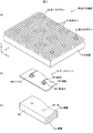
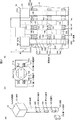
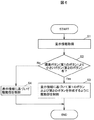
図1(a)は、実施の形態に係る触覚呈示装置の全体を示す斜視図であり、(b)は、タッチセンサの一部を示す斜視図であり、(c)は、本体の一部を示す斜視図である。図2(a)は、実施の形態に係る表示ピンの斜視図であり、(b)は、表示ピンに設けられた第1の磁石と第1の電磁石および第2の電磁石との位置の関係を示す概略図であり、(c)は、触覚呈示装置の要部断面図である。なお、実施の形態に係る各図において、部品と部品との比率は、実際の比率とは異なる場合がある。また、図2(b)および(c)では、符号の図示を容易にするため、断面を示す斜線を省略している。
(Configuration of tactile presentation device)
FIG. 1A is a perspective view showing the entirety of a tactile sense presentation device according to an embodiment, FIG. 1B is a perspective view showing a part of a touch sensor, and FIG. 1C is a part of a main body. FIG. 2A is a perspective view of the display pin according to the embodiment, and FIG. 2B is a positional relationship between the first magnet, the first electromagnet, and the second electromagnet provided on the display pin. (C) is principal part sectional drawing of a tactile sense presentation apparatus. In each drawing according to the embodiment, the ratio between parts may differ from the actual ratio. Further, in FIGS. 2B and 2C, the hatching indicating the cross section is omitted in order to facilitate the illustration of the reference numerals.
本実施の形態に係る触覚呈示装置1は、主に、複数の孔101が形成された本体10と、孔101に沿って移動する移動部材としての表示ピン12と、表示ピン12を孔101に沿った方向に駆動する駆動部14と、隣接する複数の表示ピン12からなる第1の呈示としての第1のボタン1a、および第1のボタン1aの接触面の面積よりも小さい接触面の面積を有し、本体10の表面10aから突出する第1の突出量が、第1のボタン1aが表面10aから突出する第2の突出量よりも少ない第2の呈示としての第2のボタン1b、を形成するように駆動部14を制御する制御部17と、を備えて概略構成されている。なお、第1の呈示(本実施の形態では、第1のボタン1a)の接触面の面積とは、第1の呈示を構成する表示ピン12の接触面121aの面積の総和である。よって、第1の呈示の接触面の面積よりも小さい接触面の面積とは、第2の呈示(本実施の形態では、第2のボタン1b)を構成する表示ピン12の接触面121aの面積の総和が、第1の呈示を構成する表示ピン12の接触面121aの面積の総和よりも小さいことを示している。
The tactile sense presentation device 1 according to the present embodiment mainly includes a
また、この触覚呈示装置1は、例えば、本体10の表面10a上に検出部としてのタッチセンサ16が設けられている。このタッチセンサ16は、例えば、表示ピン12へのタッチ操作、および押し下げ操作(以下プッシュ操作と記載する)を検出するように構成されている。
In addition, in the tactile sense presentation device 1, for example, a
・第1のボタン1aおよび第2のボタン1bについて
この触覚呈示装置1は、例えば、液晶ディスプレイ等に表示された表示画像に含まれるアイコンに基づいて表示ピン12を駆動し、駆動された表示ピン12と駆動されない表示ピン12とにより形成される凹凸により、当該アイコンを表現するものである。操作者は、触覚呈示装置1に視線移動することなく、触覚呈示装置1に触れることで、当該アイコンに対応する凹凸(例えば、図1(a)の第1のボタン1aおよび第2のボタン1b)を認識することができる。本実施の形態においては、第1のボタン1aを標準ボタンとし、この標準ボタンよりも構成される表示ピン12が少ないボタンの突出量を、標準ボタンの突出量よりも小さくする。
-About the
本実施の形態では、駆動されない場合の本体10に対する表示ピン12の位置を初期位置とする。この初期位置では、例えば、本体10の表面10aから表示ピン12の接触面121aまでの距離(突出量)は、最小となる。また、本実施の形態では、第1のボタン1aを形成するために駆動された場合の本体10に対する表示ピン12の位置を標準駆動位置とする。この標準駆動位置では、例えば、本体10の表面10aから表示ピン12の接触面121aまでの距離(第2の突出量)は、最大となる。さらに、本実施の形態では、第1のボタン1aよりも少ない数の表示ピン12により形成される第2のボタン1bを形成するために駆動された場合の本体10に対する表示ピン12の位置を中間駆動位置とする。この中間駆動位置では、例えば、本体10の表面10aから表示ピン12の接触面121aまでの距離(第1の突出量)は、初期位置と標準駆動位置との間(例えば、第2の突出量の1/2)の距離となる。
In the present embodiment, the position of the
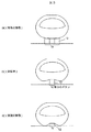
図3(a)は、実施の形態に係る第1のボタンに対するプッシュ操作を示す模式図であり、(b)は、比較例に係る第3のボタンに対するプッシュ操作を示す模式図であり、(c)は、実施の形態に係る第2のボタンに対するプッシュ操作を示す模式図である。 FIG. 3A is a schematic diagram illustrating a push operation on the first button according to the embodiment, and FIG. 3B is a schematic diagram illustrating a push operation on the third button according to the comparative example. (c) is a schematic diagram which shows push operation with respect to the 2nd button which concerns on embodiment.
本実施の形態に係る第1のボタン1aは、図1(a)および図3(a)に示すように、触覚呈示装置1の上面視にて、9つの表示ピン12によって、上面視にて一辺が6mmの正方形が形成されている。この第1のボタン1aに対してプッシュ操作が行われた場合、操作者の指は、9つの表示ピン12の頭部121に接触することとなる。
As shown in FIG. 1A and FIG. 3A, the
一方、比較例に係る第3のボタン1cは、図3(b)に示すように、第2のボタン1bと同様に、1つの表示ピン12によって、一辺が2mmの正方形が形成されている。ただし、第3のボタン1cの突出量は、第1のボタン1aと同じである。この第3のボタン1cに対してプッシュ操作が行われた場合、操作者の指は、1つの表示ピン12の頭部121に接触することとなる。つまり、比較例の第3のボタン1cに対してプッシュ操作を行う場合、操作者の指には、第1のボタン1aと比べて、およそ9倍の圧力がかかることとなる。
On the other hand, as shown in FIG. 3B, the third button 1c according to the comparative example is formed with a square having a side of 2 mm by one
本実施の形態に係る第2のボタン1bは、図1(a)および図3(b)に示すように、触覚呈示装置1の上面視にて、1つの表示ピン12によって、一辺が2mmの正方形が形成され、さらに突出量が標準駆動位置の突出量の半分となっている。
As shown in FIG. 1A and FIG. 3B, the
この第2のボタン1bに対してプッシュ操作が行われた場合、操作者の指は、1つの表示ピン12の頭部121に接触することとなるが、図3(c)に示すように、指の一部が第2のボタン1bの周囲の表示ピン12に接触するので、本実施の形態は、比較例の場合と比べて指にかかる圧力を低減することができる。
When a push operation is performed on the
なお、本実施の形態では、第2のボタン1bは、1つの表示ピン12により形成されたが、表示ピン12の大きさによっては、同じ大きさの第2のボタン1bを形成するために複数の表示ピン12が必要となる。この場合には、第2のボタン1bを形成する複数の表示ピン12が、中間駆動位置となる。
In the present embodiment, the
・本体10の構成
本体10は、例えば、孔101により表示ピン12の移動を案内し、所定の厚みを有する直方体形状の部材である。また、本体10は、例えば、図1(a)に示すようにx方向、およびこのx方向に直交するy方向、に沿って複数の孔101が形成されている。なお、表示ピン12の軸部120と孔101との間には、摩擦を軽減するグリス等が介在しても良く、また、軸部120を支持する軸受けが本体10に形成されていても良い。
Structure of the
本実施の形態では、x方向に27個、y方向に20個(合計540個)の孔101が本体10に形成されている。また、本体10の表面10aおよび裏面10bは、例えば、平坦である。孔101は、その中心軸が表面10aに対して直交するように形成されている。また、本実施の形態に係る孔101は、例えば、底部102を有する孔であるが、これに限定されず、貫通する孔であっても良い。本実施の形態の表示ピン12は、例えば、初期位置にあるとき、孔101の底部102に軸部120の端部122が接触するものとする。
In the present embodiment, 27
なお、x方向またはy方向に隣り合う孔101の中心間距離は、例えば、x方向およびy方向とも2.0〜3.0mmであることが好ましい。
In addition, it is preferable that the distance between the centers of the
・表示ピンの構成
表示ピン12は、例えば、図2(a)に示すように、円柱形状を有する軸部120と、軸部120の一方端部に形成された頭部121と、を備えて概略構成されている。この表示ピン12の数は、孔101の数と同数(合計540個)である。
Display Pin Configuration The
表示ピン12は、例えば、図2(c)に示すように、初期位置にあるとき、本体10の表面10aから表示ピン12の接触面121aまでの距離(突出量)は、一例として3mmである。表示ピン12は、例えば、標準駆動位置にあるとき、突出量は、一例として5mmである。表示ピン12は、例えば、中間位置にあるとき、突出量は、一例として4mmである。
For example, as shown in FIG. 2C, when the
軸部120は、例えば、樹脂材料を用いて形成される。また、軸部120は、例えば、他方端部側である端部122から頭部121に向って、軸部120の短手方向に貫通する貫通孔123〜貫通孔125を有する。
The
軸部120における貫通孔123の形成される位置は、例えば、表示ピン12の最小の突出量に応じて定められている。
The position where the through hole 123 is formed in the
貫通孔123の中心と貫通孔125の中心との間隔は、例えば、表示ピン12の最大の突出量に応じて定められている。駆動部14は、例えば、図1(a)に示す第1のボタン1aを形成する場合、隣接する表示ピン12(合計9個)を最大の突出量で駆動する。
The distance between the center of the through hole 123 and the center of the through
また、本実施の形態における、貫通孔123の中心と貫通孔124の中心との間隔は、例えば、表示ピン12の最小の突出量と最大の突出量との中間の突出量に応じて定められている。触覚呈示装置1は、例えば、図1(a)に示す第2のボタン1bを形成する場合、第2のボタン1bに対応する位置に有る表示ピン12を中間の突出量で駆動する。
In the present embodiment, the distance between the center of the through hole 123 and the center of the through
貫通孔123には、例えば、第1の磁石130が挿入されている。貫通孔124には、例えば、第2の磁石131が挿入されている。貫通孔125には、例えば、第3の磁石132が挿入されている。この第1の磁石130〜第3の磁石132は、例えば、ネオジム磁石を用いて形成される。
For example, a
頭部121は、例えば、正六面体(立方体)である。本実施の形態における頭部121は、例えば、導電性を有する導電材料を用いて形成される。頭部121は、導電材料を用いて形成されることで、操作者とタッチセンサ16の電極162の間に介在することとなり、タッチセンサ16の感度が向上する。頭部121の辺の長さは、一例として、2mmである。なお、頭部121は、例えば、軸部120と同じ材料から形成されても良い。
The
なお、本実施の形態に係る変形例として、表示ピン12は、頭部121を持たない形状であっても良い。また、表示ピン12は、軸部120が円柱形状であったが、他の柱体形状であっても良い。さらに、表示ピン12は、1つの磁石を備え、この磁石に対する反発力と吸引力により駆動されても良い。
As a modification according to the present embodiment, the
・駆動部14の構成
駆動部14は、例えば、図2(c)に示すように、それぞれの孔101の長手方向の側面に沿って、第1の電磁石141〜第6の電磁石146を有して概略構成されている。つまり、駆動部14は、表示ピン12の数と同じ数の第1の電磁石141〜第6の電磁石146を備えている。
-Structure of the
第1の電磁石141は、図2(b)および(c)に示すように、第2の電磁石142と孔101を介して対向している。第3の電磁石143は、図2(c)に示すように、第4の電磁石144と孔101を介して対向している。第5の電磁石145は、図2(c)に示すように、第6の電磁石146と孔101を介して対向している。続いて、以下では、第1の電磁石141〜第6の電磁石146の構成を、第1の電磁石141を例として説明する。第2の電磁石142〜第6の電磁石146は、例えば、この第1の電磁石141と同じ構成を有する。
As shown in FIGS. 2B and 2C, the
第1の電磁石141は、例えば、図2(b)に示すように、コイル141aと、ヨーク141bと、を備えて概略構成されている。
For example, as shown in FIG. 2B, the
コイル141aは、例えば、導電性を有する線材(例えば、銅線)が芯141cの周囲に巻き回されることにより形成されるものである。
The
ヨーク141bは、例えば、一方端部に開口が設けられた円柱形状を有し、その開口内に、円柱形状を有する芯141cが設けられている。また、ヨーク141bおよび芯141cは、例えば、軟鉄等の軟磁性体材料を用いて形成される。
The
芯141cは、図2(b)に示すように、表示ピン12の軸部120側のヨーク141bの端部よりも軸部120方向に突出しているので、発生する磁場が軸部120方向に集中することとなる。
As shown in FIG. 2B, the core 141c protrudes in the direction of the
これらの電磁石(第1の電磁石141〜第6の電磁石146)の芯141cは、コイル141aに電流が流れていないとき、近傍に位置する軸部120の磁石(第1の磁石130〜第3の磁石132)との間に吸引力が発生する。つまり、表示ピン12は、芯141cと対向する磁石とによる静止トルクにより、本体10に対する表示ピン12の位置が保持される。
The
なお、本実施の形態に係る変形例として、駆動部14は、1つの駆動位置に対して1つの電磁石が配置されたり、孔101の周囲に3つ以上配置されたりしても良い。また、電磁石は、軸部120側と軸部120の反対側が同じ構成、つまり、軸部120の反対側にも軸部120側のように、磁場が集中する構成とし、1つの電磁石で、隣接する2つの表示ピン12を駆動または保持する構成としても良い。
As a modification according to the present embodiment, one electromagnet may be arranged for one driving position, or three or more around the
・タッチセンサ16の構成
タッチセンサ16は、例えば、操作者の指が表示ピン12の接触面121aに接近、または接触することによる、操作者と当該表示ピン12の頭部121直下の電極162との間の静電容量の変化に基づいてタッチ操作およびプッシュ操作を検出する静電容量方式のセンサである。また、タッチセンサ16は、静電容量の変化に基づいたタッチ信号を制御部17に出力するように構成されている。ここで、タッチ操作とは、表示ピン12の頭部121の接触面121aに、操作者が接触する、または変化が検出できるほど指等を接近させる操作を示す。また、プッシュ操作とは、表示ピン12を本体10の表面10aから裏面10b方向に移動させる操作である。
-Configuration of the
タッチセンサ16は、例えば、図1(b)に示すように、FPC(フレキシブル基板:Flexible printed circuits)160と、複数の電極162と、複数の電極162のそれぞれと電気的に接続する複数の配線163と、を備えて概略構成されている。FPC160は、例えば、ポリイミド等を用いてフィルム形状に形成される。また、電極162および配線163は、例えば、銅等の導電性を有する導電材料を用いて形成される。FPC160は、本体10に形成された孔101に対応して複数の貫通孔161が形成されている。電極162は、この貫通孔161の周囲に形成されている。
For example, as shown in FIG. 1B, the
・制御部17の構成
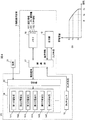
図4(a)は、実施の形態に係る触覚呈示装置のブロック図であり、(b)は、距離と静電容量との関係を示すグラフである。図4(b)は、横軸が電極162と表示ピン12の接触面121aまでの距離であり、縦軸が操作者とタッチセンサ16の電極162とにより形成されるコンデンサの静電容量である。なお、図4(b)では、操作者の指と電極162との距離がd3以上となる場合は、静電容量がゼロとなるように構成されている。また図4(b)では、初期位置にある表示ピン12と電極162との距離d1以下にすることができないため、距離d1〜距離d3までの静電容量を図示している。
FIG. 4A is a block diagram of the tactile sensation presentation apparatus according to the embodiment, and FIG. 4B is a graph showing the relationship between the distance and the capacitance. In FIG. 4B, the horizontal axis represents the distance between the
触覚呈示装置1は、例えば、図4(a)に示すように、制御部17と、メモリ18と、通信部19と、切替部20と、を備えて概略構成されている。また、触覚呈示装置1は、例えば、図4(a)に示すように、動作に必要な電流が電源21から供給されている。
For example, as shown in FIG. 4A, the tactile sensation presentation apparatus 1 is schematically configured to include a
制御部17は、例えば、CPU(Central Processing Unit)、RAM(Random Access Memory)およびROM(Read Only Memory)を備えたマイクロコンピュータである。制御部17は、例えば、メモリ18に格納された設定情報180および呈示情報182に基づいて、各表示ピン12に対応する第1の電磁石141〜第6の電磁石146を制御する駆動信号を生成して、切替部20に出力するように構成されている。この設定情報180とは、例えば、表示ピン12の駆動に必要な情報を含む。また、呈示情報182とは、例えば、通信部19を介して取得されてメモリ18に格納された情報であり、表示ピン12の駆動により呈示されるボタンの大きさ、数、および形成する位置等の情報を含む。
The
なお、触覚呈示装置1は、通信部19を介して呈示情報182を取得する構成に限定されず、呈示情報182は、予めメモリ18に格納されていても良い。なお、メモリ18は、例えば、制御部17内(例えば、RAM)に備えられていても良い。
The tactile sensation presentation device 1 is not limited to the configuration for obtaining the presentation information 182 via the
また、制御部17は、例えば、タッチセンサ16が出力するタッチ信号、およびメモリ18に格納されたしきい値情報181に基づいてどの表示ピン12に対してタッチ操作およびプッシュ操作が行われたかを判定するように構成されている。また、制御部17は、例えば、ある表示ピン12に対してプッシュ操作が行われた場合、プッシュ操作がなされた表示ピン12の情報等を入力情報として通信部19を介して出力するように構成されている。
For example, the
切替部20は、例えば、制御部17から出力される駆動信号に基づいて電流を供給する電磁石を切り替えるように構成されている。また、切替部20は、例えば、駆動信号に基づいて電磁石に供給する電流の方向を変えることにより、電磁石の磁極を変えることができるように構成されている。
The switching
なお、本実施の形態に係る変形例として、電磁石のコイルが、巻き方向が異なる2つのコイルから構成され、切替部20は、駆動信号に基づいてこのコイルを切り替えることにより、磁極を変化させる構成としても良い。
As a modification according to the present embodiment, the electromagnet coil is composed of two coils having different winding directions, and the switching
以下では、本実施の形態に係る触覚呈示装置の動作である、「表示ピンが初期位置から標準駆動位置まで駆動される動作」、「表示ピンが標準駆動位置から初期位置まで駆動される動作」および「タッチ操作とプッシュ操作の検出動作」について、各図を参照しながら説明する。 In the following, the operations of the tactile sense presentation device according to the present embodiment are “an operation in which the display pin is driven from the initial position to the standard driving position”, and “an operation in which the display pin is driven from the standard driving position to the initial position”. And “detection operation of touch operation and push operation” will be described with reference to each drawing.
(表示ピンが初期位置から標準駆動位置まで駆動される動作について)
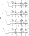
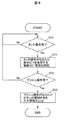
図5(a)〜(d)は、実施の形態に係る触覚呈示装置の表示ピンが初期位置から標準駆動位置まで駆動される動作を示す模式図である。図6は、実施の形態に係る触覚呈示装置の動作に関するフローチャートである。まず、触覚呈示装置1の表示ピン12が、全て初期位置にある状態から、図1(a)に示す第1のボタン1aおよび第2のボタン1bを形成する動作を、図6のフローチャートに従って説明する。
(Operations in which the display pin is driven from the initial position to the standard drive position)
FIGS. 5A to 5D are schematic diagrams illustrating an operation in which the display pin of the tactile sense presentation device according to the embodiment is driven from the initial position to the standard driving position. FIG. 6 is a flowchart relating to the operation of the tactile sense presentation device according to the embodiment. First, the operation of forming the
触覚呈示装置1の制御部17は、呈示情報182を取得する(S1)。具体的には、制御部17は、通信部19を介して呈示情報182を取得、またはメモリ18に格納された呈示情報182を取得する。
The
次に、制御部17は、取得した呈示情報182に基づいて、標準ボタン(第1のボタン1a)より小さいボタン(第2のボタン1b)があるか否かを判定する(S2)。
Next, the
次に、制御部17は、標準ボタンより小さいボタンがあるとき(S2:Yes)、標準ボタン(第1のボタン1a)および標準ボタンより小さいボタン(第2のボタン1b)を形成するように駆動部14を制御する(S3)。以下に、第1のボタン1aの形成について、第1のボタン1aを構成する表示ピン12aを例として説明する。
Next, when there is a button smaller than the standard button (S2: Yes), the
・第1の動作
まず、制御部17は、第1の電磁石141〜第4の電磁石144を駆動するための駆動信号を切替部20に出力する。切替部20は、図5(a)に示すように、当該駆動信号に基づいて第1の磁石130のN極に対向する側の第1の電磁石141の磁極がN極となるように、電源21から出力された電流を供給する。また、切替部20は、図5(a)に示すように、当該駆動信号に基づいて第1の磁石130のS極に対向する側の第2の電磁石142の磁極がS極となるように、電源21から出力された電流を供給する。また、切替部20は、図5(a)に示すように、当該駆動信号に基づいて第2の磁石131のN極側の第3の電磁石143の磁極がS極となるように、電源21から出力された電流を供給する。さらに、切替部20は、図5(a)に示すように、当該駆動信号に基づいて第2の磁石131のS極側の第4の電磁石144の磁極がN極となるように、電源21から出力された電流を供給する。
First Operation First, the
この第1の動作では、表示ピン12の第1の磁石130と、第1の電磁石141および第2の電磁石142とには、同じ磁極が対向することにより、互いに反発する力(以下反発力と記載)が発生するとともに、第2の磁石131と、第3の電磁石および第4の電磁石144とには、異なる磁極が接近していることにより、互いに引き合う力(以下吸引力と記載)が発生する。従って、表示ピン12aは、図5(a)の上方向に駆動される。
In the first operation, the
・第2の動作
次に、制御部17は、図5(b)に示すように、新たに駆動信号を出力して切替部20を制御し、第1の電磁石141〜第4の電磁石144に対する電流の供給を停止する。
Second Operation Next, as shown in FIG. 5B, the
この第2の動作では、表示ピン12aの第2の磁石131が第3の電磁石143および第4の電磁石144と対向する位置にあり、第2の磁石131と、第3の電磁石143および第4の電磁石144のヨーク141bおよび芯141cとに吸引力が発生する。従って、表示ピン12aは、図5(b)に示す中間駆動位置に保持される。つまり、第2のボタン1bは、上記の第1の動作および第2の動作を経て形成される。
In this second operation, the
・第3の動作
次に、制御部17は、第3の電磁石143〜第6の電磁石146を駆動するための駆動信号を切替部20に出力する。切替部20は、図5(c)に示すように、当該駆動信号に基づいて第2の磁石131のN極に対向する側の第3の電磁石143の磁極がN極となるように、電源21から出力された電流を供給する。また、切替部20は、図5(c)に示すように、当該駆動信号に基づいて第2の磁石131のS極に対向する側の第4の電磁石144の磁極がS極となるように、電源21から出力された電流を供給する。また、切替部20は、図5(c)に示すように、当該駆動信号に基づいて第3の磁石132のN極側の第5の電磁石145の磁極がS極となるように、電源21から出力された電流を供給する。さらに、切替部20は、図5(c)に示すように、当該駆動信号に基づいて第3の磁石132のS極側の第6の電磁石146の磁極がN極となるように、電源21から出力された電流を供給する。
Third Operation Next, the
この第3の動作では、表示ピン12の第2の磁石131と、第3の電磁石143および第4の電磁石144とには、同じ磁極が対向することにより、互いに反発力が発生するとともに、第3の磁石132と、第5の電磁石145および第6の電磁石146とには、異なる磁極が接近していることにより、互いに吸引力が発生する。従って、表示ピン12aは、図5(c)の上方向に駆動される。
In the third operation, the
・第4の動作
次に、制御部17は、図5(d)に示すように、新たに駆動信号を出力して切替部20を制御し、第3の電磁石143〜第6の電磁石146に対する電流の供給を停止する。
-4th operation | movement Next, as shown in FIG.5 (d), the
この第4の動作では、表示ピン12aの第3の磁石132が第5の電磁石145および第6の電磁石146と対向する位置にあり、第3の磁石132と、第5の電磁石145および第6の電磁石146のヨーク141bおよび芯141cとに吸引力が発生する。従って、表示ピン12aは、図5(d)に示す標準駆動位置に保持される。つまり、第1のボタン1aは、上記の第1の動作〜第4の動作を経て形成される。
In the fourth operation, the
ここで、ステップ2において、第2のボタン1bを形成しないとき(S2:No)、制御部17は、第1のボタン1aを形成するように駆動部14を制御する(S4)。具体的には、触覚呈示装置1は、上記の第1の動作〜第4の動作を対象となる表示ピン12に対して行い、少なくとも1つの第1のボタン1aを形成し動作を終了する。
Here, in step 2, when the
(表示ピンが標準駆動位置から初期位置まで駆動される動作について)
続いて、駆動された表示ピン12aを初期位置に移動させる動作について説明する。
(Operations in which the display pin is driven from the standard drive position to the initial position)
Next, an operation for moving the driven
図7(a)〜(d)は、実施の形態に係る触覚呈示装置の表示ピンが標準駆動位置から初期位置まで駆動される動作を示す模式図である。 FIGS. 7A to 7D are schematic diagrams illustrating an operation in which the display pin of the tactile sense presentation device according to the embodiment is driven from the standard drive position to the initial position.
・第5の動作
まず、制御部17は、第3の電磁石143〜第6の電磁石146を駆動するための駆動信号を切替部20に出力する。切替部20は、図7(a)に示すように、当該駆動信号に基づいて第3の磁石132のN極に対向する側の第5の電磁石145の磁極がN極となるように、電源21から出力された電流を供給する。また、切替部20は、図7(a)に示すように、当該駆動信号に基づいて第3の磁石132のS極に対向する側の第6の電磁石146の磁極がS極となるように、電源21から出力された電流を供給する。また、切替部20は、図7(a)に示すように、当該駆動信号に基づいて第2の磁石131のN極側の第3の電磁石143の磁極がS極となるように、電源21から出力された電流を供給する。さらに、切替部20は、図7(a)に示すように、当該駆動信号に基づいて第2の磁石131のS極側の第4の電磁石144の磁極がN極となるように、電源21から出力された電流を供給する。
-5th operation First, the
この第5の動作では、表示ピン12の第3の磁石132と、第5の電磁石145および第6の電磁石146とには、同じ磁極が対向することにより、互いに反発力が発生するとともに、第2の磁石131と、第3の電磁石143および第4の電磁石144とには、異なる磁極が接近していることにより、互いに吸引力が発生する。従って、表示ピン12aは、図7(a)の下方向に駆動される。
In the fifth operation, the
・第6の動作
次に、制御部17は、図7(b)に示すように、新たに駆動信号を出力して切替部20を制御し、第3の電磁石143〜第6の電磁石146に対する電流の供給を停止する。
-6th operation Next, as shown in FIG.7 (b), the
この第6の動作では、表示ピン12aの第2の磁石131が第3の電磁石143および第4の電磁石144と対向する位置にあり、第2の磁石131と、第3の電磁石143および第4の電磁石144のヨーク141bおよび芯141cとに吸引力が発生する。従って、表示ピン12aは、図7(b)に示す中間駆動位置に保持される。
In the sixth operation, the
・第7の動作
次に、制御部17は、第1の電磁石141〜第4の電磁石144を駆動するための駆動信号を切替部20に出力する。切替部20は、図7(c)に示すように、当該駆動信号に基づいて第2の磁石131のN極に対向する側の第3の電磁石143の磁極がN極となるように、電源21から出力された電流を供給する。また、切替部20は、図7(c)に示すように、当該駆動信号に基づいて第2の磁石131のS極に対向する側の第4の電磁石144の磁極がS極となるように、電源21から出力された電流を供給する。また、切替部20は、図7(c)に示すように、当該駆動信号に基づいて第1の磁石130のN極側の第1の電磁石141の磁極がS極となるように、電源21から出力された電流を供給する。さらに、切替部20は、図7(c)に示すように、当該駆動信号に基づいて第1の磁石130のS極側の第2の電磁石142の磁極がN極となるように、電源21から出力された電流を供給する。
-7th operation | movement Next, the
この第7の動作では、表示ピン12の第2の磁石131と、第3の電磁石143および第4の電磁石144とには、同じ磁極が対向することにより、互いに反発力が発生するとともに、第1の磁石131と、第1の電磁石141および第2の電磁石142とには、異なる磁極が接近していることにより、互いに吸引力が発生する。従って、表示ピン12aは、図7(c)の下方向に駆動される。
In the seventh operation, the
・第8の動作
次に、制御部17は、図7(d)に示すように、新たに駆動信号を出力して切替部20を制御し、第1の電磁石141〜第4の電磁石144に対する電流の供給を停止する。
-Eighth operation Next, as shown in FIG.7 (d), the
この第8の動作では、表示ピン12aの第1の磁石130が第1の電磁石141および第2の電磁石142と対向する位置にあり、第1の磁石130と、第1の電磁石141および第2の電磁石142のヨーク141bおよび芯141cとに吸引力が発生する。従って、表示ピン12aは、図7(d)に示す初期位置に保持される。
In the eighth operation, the
(タッチ操作とプッシュ操作の検出動作について)
続いて、表示ピン12になされたタッチ操作とプッシュ操作の検出動作について、図8のフローチャートに従って説明する。
(About detection of touch operation and push operation)
Next, the detection operation of the touch operation and the push operation performed on the
まず、制御部17は、タッチセンサ16から出力されるタッチ信号に基づいてタッチ操作の有無を判定する(S10)。制御部17は、例えば、取得したタッチ信号としきい値情報181と、に基づいて判定を行う。
First, the
制御部17は、タッチ操作がなされたと判定すると(S10:Yes)、タッチ信号に基づいてタッチ操作がなされた表示ピン12を保持する電磁石に、電源21を介して電流を供給する(S11)。言い換えるなら、制御部17は、タッチセンサ16がタッチ操作を検出した後、タッチ操作がなされた表示ピン12の位置を保持する電磁石に電流を供給することにより、タッチ操作がなされた表示ピン12を駆動部14に保持させる。
When determining that the touch operation has been performed (S10: Yes), the
具体的には、まず、制御部17は、タッチ信号に基づいてタッチ操作がなされた表示ピン12を特定する。続いて、制御部17は、呈示情報182に基づいて当該表示ピン12の位置を特定し、その位置を保持する電磁石を特定する。
Specifically, first, the
例えば、当該表示ピン12が中間駆動位置にある場合、当該表示ピン12を保持する電磁石は、第3の電磁石143および第4の電磁石144である。従って、制御部17は、第2の磁石131のN極に対向する第3の電磁石143の磁極がS極となるように、切替部20を制御して、電源21から出力される電流を供給する。また、制御部17は、第2の磁石131のS極に対向する第4の電磁石144の磁極がN極となるように、切替部20を制御して、電源21から出力される電流を供給する。
For example, when the
この電流の供給により、第2の磁石131と、第3の電磁石143および第4の電磁石144とには、吸引力が発生する。従って、触覚呈示装置1は、ヨーク141bおよび芯141cにより保持される場合よりも強く、中間駆動位置を保持することができる。また、操作者が当該表示ピン12に対しプッシュ操作を行うと、当該表示ピン12は、プッシュ操作方向(例えば、図2(c)の下方向)に移動するものの、上記の吸引力により中間駆動位置に復帰することとなる。つまり、電磁石に電流が供給されることにより、操作者は、適度な操作感を得ることができる。
By supplying this current, an attractive force is generated in the
また、例えば、当該表示ピン12が標準駆動位置にある場合、当該表示ピン12を保持する電磁石は、第5の電磁石145および第6の電磁石146である。従って、制御部17は、第3の磁石132のN極に対向する第5の電磁石145の磁極がS極となるように、切替部20を制御して、電源21から出力される電流を供給する。また、制御部17は、第3の磁石132のS極に対向する第6の電磁石146の磁極がN極となるように、切替部20を制御して、電源21から出力される電流を供給する。
For example, when the
この電流の供給により、第3の磁石132と、第5の電磁石145および第6の電磁石146とには、吸引力が発生する。従って、触覚呈示装置1は、ヨーク141bおよび芯141cにより保持される場合よりも強く、標準駆動位置を保持することができる。また、操作者が当該表示ピン12に対しプッシュ操作を行うと、当該表示ピン12は、プッシュ操作方向(例えば、図2(c)の下方向)に移動するものの、上記の吸引力により標準駆動位置に復帰することとなる。つまり、電磁石に電流が供給されることにより、操作者は、適度な操作感を得ることができる。
By supplying this current, an attractive force is generated in the
制御部17は、タッチ操作の判定を行った後、プッシュ操作の有無を判定する(S12)。
After determining the touch operation, the
具体的には、制御部17は、タッチ信号から得られる静電容量と、しきい値情報181と、に基づいてプッシュ操作の有無を判定する。つまり、図4(b)に示すように、例えば、中間駆動位置にある表示ピン12に対してプッシュ操作がなされた場合、制御部17は、しきい値情報181から得られた中間駆動位置の静電容量C2と、タッチ信号から得られた静電容量と、を比較する。操作者と、タッチセンサ16の電極162と、の距離が近い方が、静電容量は大きくなるので、制御部17は、タッチ信号から得られた静電容量が、静電容量C2よりも大きくなると、プッシュ操作がなされたと判定する。
Specifically, the
また、例えば、標準駆動位置にある表示ピン12に対してプッシュ操作がなされた場合、制御部17は、しきい値情報181から得られた標準駆動位置の静電容量C3と、タッチ信号から得られた静電容量と、を比較する。制御部17は、タッチ信号から得られた静電容量が、静電容量C3よりも大きくなると、プッシュ操作がなされたと判定する。
Further, for example, when a push operation is performed on the
制御部17は、プッシュ操作がなされたと判定すると(S12:Yes)、プッシュ操作がなされたボタンの情報を含む入力信号を、通信部19を介して出力する(S13)。ここで、制御部17は、ステップ12において、所定の時間プッシュ操作が行われない、またはタッチ操作が解除されたとき(S12:No)、ステップ10に戻って処理を続ける。
When the
(実施の形態の効果)
本実施の形態に係る触覚呈示装置1によれば、表示ピン12に対するプッシュ操作において、操作者の指にかかる圧力を抑制することができる。具体的には、触覚呈示装置1は、標準ボタン(第1のボタン1a)の接触面の面積よりも小さい接触面の面積を有するボタン(第2のボタン1b)の突出量を、標準ボタンの突出量よりも少なくすることにより、指がボタンの周囲に接触することで、小さいボタンの突出量が大きい場合と比べて、表示ピン12から受ける圧力が低減する。
(Effect of embodiment)
According to the tactile sense presentation device 1 according to the present embodiment, it is possible to suppress the pressure applied to the operator's finger in the push operation on the
また、触覚呈示装置1は、駆動部14によって、表示ピン12の駆動と保持ができるので、別々に機構を必要とする場合と比べて、構成が少なく、製造コストを抑制することができる。また、触覚呈示装置1は、電磁石のヨーク141bおよび芯141cにより、表示ピン12を保持することができるので、保持に電流が必要な場合と比べて、消費電力を抑制することができる。
In addition, since the tactile sense presentation device 1 can drive and hold the
また、触覚呈示装置1は、タッチセンサ16により、タッチ操作およびプッシュ操作を検出することができるので、タッチ操作とプッシュ操作の検出を別々の構成で行う場合と比べて、構成が少なく、製造コストを抑制することができる。また、触覚呈示装置1は、タッチ操作を検出することにより、タッチ操作がなされた表示ピン12に対応する電磁石に電流を供給し、表示ピン12を保持する力を増加させることができる。また、触覚呈示装置1は、この保持する力により、操作者に操作感を付与することができる。
The tactile sense presentation device 1 can detect a touch operation and a push operation with the
なお、本実施の形態に係る触覚呈示装置1は、電磁石により表示ピンを駆動および保持する構成としたが、これに限定されず、表示ピンをアクチュエータで駆動する構成、アクチュエータで駆動した表示ピンを保持機構により保持する構成等の周知の構成を用いても良い。 The tactile sensation presentation apparatus 1 according to the present embodiment is configured to drive and hold the display pin with an electromagnet. However, the present invention is not limited thereto, and the display pin is driven with an actuator. A known configuration such as a configuration of holding by a holding mechanism may be used.
以上、本発明のいくつかの実施の形態を説明したが、これらの実施の形態は、一例に過ぎず、特許請求の範囲に係る発明を限定するものではない。これら新規な実施の形態は、その他の様々な形態で実施されることが可能であり、本発明の要旨を逸脱しない範囲で、種々の省略、置き換え、変更等を行うことができる。また、これら実施の形態の中で説明した特徴の組合せの全てが発明の課題を解決するための手段に必須であるとは限らない。さらに、これら実施の形態は、発明の範囲及び要旨に含まれるとともに、特許請求の範囲に記載された発明とその均等の範囲に含まれる。 As mentioned above, although some embodiment of this invention was described, these embodiment is only an example and does not limit the invention which concerns on a claim. These novel embodiments can be implemented in various other forms, and various omissions, replacements, changes, and the like can be made without departing from the scope of the present invention. In addition, not all the combinations of features described in these embodiments are essential to the means for solving the problems of the invention. Furthermore, these embodiments are included in the scope and gist of the invention, and are included in the invention described in the claims and the equivalents thereof.
1…触覚呈示装置、1a…第1のボタン、1b…第2のボタン、10…本体、10a…表面、10b…裏面、12…表示ピン、12a…表示ピン、14…駆動部、16…タッチセンサ、17…制御部、18…メモリ、19…通信部、20…切替部、21…電源、101…孔、102…底部、120…軸部、121…頭部、121a…接触面、122…端部、123〜125…貫通孔、130〜132…第1の磁石〜第3の磁石、140…貫通孔、141〜146…第1の電磁石〜第6の電磁石、141a…コイル、141b…ヨーク、141c…芯、160…FPC、161…貫通孔、162…電極、163…配線、180…設定情報、181…しきい値情報、182…呈示情報 DESCRIPTION OF SYMBOLS 1 ... Tactile sense presentation apparatus, 1a ... 1st button, 1b ... 2nd button, 10 ... Main body, 10a ... Front surface, 10b ... Back surface, 12 ... Display pin, 12a ... Display pin, 14 ... Drive part, 16 ... Touch Sensor, 17 ... Control part, 18 ... Memory, 19 ... Communication part, 20 ... Switching part, 21 ... Power source, 101 ... Hole, 102 ... Bottom part, 120 ... Shaft part, 121 ... Head, 121a ... Contact surface, 122 ... Ends, 123 to 125 ... through holes, 130 to 132 ... first magnet to third magnet, 140 ... through holes, 141 to 146 ... first electromagnet to sixth electromagnet, 141a ... coil, 141b ... yoke , 141c ... core, 160 ... FPC, 161 ... through hole, 162 ... electrode, 163 ... wiring, 180 ... setting information, 181 ... threshold information, 182 ... presentation information
Claims (3)
前記孔に沿って移動する移動部材と、
前記移動部材を前記孔に沿った方向に駆動する駆動部と、
隣接する複数の移動部材からなる第1の呈示、および前記第1の呈示の接触面の面積よりも小さい接触面の面積を有し、前記本体の表面から突出する第1の突出量が、前記第1の呈示が前記表面から突出する第2の突出量よりも少ない第2の呈示、を形成するように前記駆動部を制御する制御部と、
を備えた触覚呈示装置。 A main body formed with a plurality of holes;
A moving member that moves along the hole;
A drive unit for driving the moving member in a direction along the hole;
A first presentation comprising a plurality of adjacent moving members, and a first projection amount projecting from a surface of the main body, the first projection amount having an area of a contact surface smaller than an area of the contact surface of the first presentation, A controller that controls the drive so as to form a second presentation, wherein the first presentation is less than a second projection amount projecting from the surface;
A tactile presentation device.
前記駆動部は、前記少なくとも1つの磁石との間に発生する吸引力により、前記本体に対する前記移動部材の位置を保持する軟磁性体を有する複数の電磁石を含む請求項1に記載の触覚呈示装置。 The moving member has at least one magnet;
2. The tactile sense presentation device according to claim 1, wherein the driving unit includes a plurality of electromagnets having a soft magnetic body that holds a position of the moving member with respect to the main body by an attractive force generated between the at least one magnet. .
Priority Applications (1)
| Application Number | Priority Date | Filing Date | Title |
|---|---|---|---|
| JP2011056395A JP2012194635A (en) | 2011-03-15 | 2011-03-15 | Tactile sense presentation device |
Applications Claiming Priority (1)
| Application Number | Priority Date | Filing Date | Title |
|---|---|---|---|
| JP2011056395A JP2012194635A (en) | 2011-03-15 | 2011-03-15 | Tactile sense presentation device |
Publications (1)
| Publication Number | Publication Date |
|---|---|
| JP2012194635A true JP2012194635A (en) | 2012-10-11 |
Family
ID=47086505
Family Applications (1)
| Application Number | Title | Priority Date | Filing Date |
|---|---|---|---|
| JP2011056395A Withdrawn JP2012194635A (en) | 2011-03-15 | 2011-03-15 | Tactile sense presentation device |
Country Status (1)
| Country | Link |
|---|---|
| JP (1) | JP2012194635A (en) |
Cited By (1)
| Publication number | Priority date | Publication date | Assignee | Title |
|---|---|---|---|---|
| JP2016502187A (en) * | 2013-03-04 | 2016-01-21 | シャオミ・インコーポレイテッド | PHYSICAL FEEDBACK SYSTEM AND ITS CONTROL METHOD, DEVICE, DISPLAY ASSEMBLY, ELECTRONIC DEVICE, PROGRAM, RECORDING MEDIUM |
-
2011
- 2011-03-15 JP JP2011056395A patent/JP2012194635A/en not_active Withdrawn
Cited By (2)
| Publication number | Priority date | Publication date | Assignee | Title |
|---|---|---|---|---|
| JP2016502187A (en) * | 2013-03-04 | 2016-01-21 | シャオミ・インコーポレイテッド | PHYSICAL FEEDBACK SYSTEM AND ITS CONTROL METHOD, DEVICE, DISPLAY ASSEMBLY, ELECTRONIC DEVICE, PROGRAM, RECORDING MEDIUM |
| US9965066B2 (en) | 2013-03-04 | 2018-05-08 | Xiaomi Inc. | Physical feedback system, control method and electronic device |
Similar Documents
| Publication | Publication Date | Title |
|---|---|---|
| US10692668B2 (en) | Force feedback surface for an electronic device | |
| US10509526B2 (en) | Three-dimensional touch control structure and display device | |
| US9503083B2 (en) | Force feedback-type touch panel device | |
| US10496173B2 (en) | Manipulation feeling imparting input device | |
| US11372482B2 (en) | Electronic device with updating of the baseline of a force sensor used to detect user pressing a display screen | |
| US7319374B2 (en) | Moving magnet actuator | |
| US20180095536A1 (en) | Vibration generating device and manipulation feeling imparting input device using the vibration generating device | |
| JP5573374B2 (en) | Information processing apparatus and operation input method | |
| JP5515511B2 (en) | Input device and information processing device | |
| US20100123685A1 (en) | Tactile presentation touch screen and display device having the same | |
| CN103765347B (en) | Operating device | |
| JP2025081767A (en) | Vibration presenting apparatus | |
| US20170063212A1 (en) | Vibration generator and electronic device having the same | |
| JP2012194634A (en) | Tactile sense presentation device | |
| JP6418642B2 (en) | Input device | |
| JP4773330B2 (en) | Display device | |
| JP2012194635A (en) | Tactile sense presentation device | |
| JP2019194833A (en) | Electronic apparatus and control method for electronic apparatus | |
| KR101036616B1 (en) | External force response haptic providing device using electromagnetic induction phenomenon, haptic providing module using the same, portable terminal using the same and its control method | |
| JP6117075B2 (en) | Tactile presentation device | |
| JP2012194636A (en) | Tactile sense presentation device | |
| JP2012238270A (en) | Input device | |
| JP2011258389A (en) | Operation input apparatus | |
| JP2014006632A (en) | Tactile sense presentation device | |
| JP4745412B2 (en) | Input device and electronic device |
Legal Events
| Date | Code | Title | Description |
|---|---|---|---|
| A300 | Application deemed to be withdrawn because no request for examination was validly filed |
Free format text: JAPANESE INTERMEDIATE CODE: A300 Effective date: 20140603 |