JP2012194424A - Projector and control method for projector - Google Patents
Projector and control method for projector Download PDFInfo
- Publication number
- JP2012194424A JP2012194424A JP2011059065A JP2011059065A JP2012194424A JP 2012194424 A JP2012194424 A JP 2012194424A JP 2011059065 A JP2011059065 A JP 2011059065A JP 2011059065 A JP2011059065 A JP 2011059065A JP 2012194424 A JP2012194424 A JP 2012194424A
- Authority
- JP
- Japan
- Prior art keywords
- image
- vertex
- projection
- projection image
- projector
- Prior art date
- Legal status (The legal status is an assumption and is not a legal conclusion. Google has not performed a legal analysis and makes no representation as to the accuracy of the status listed.)
- Withdrawn
Links
Images


Abstract
Description
本発明は、プロジェクター、及び、プロジェクターの制御方法に関する。 The present invention relates to a projector and a method for controlling the projector.
従来、スクリーンに画像を投射する場合に発生する台形歪みを補正する機能を有するプロジェクターが知られている(例えば、特許文献1参照。)。特許文献1記載のプロジェクターは、タッチパッドを備え、このタッチパッドの操作により台形歪みの補正量及び補正方向を指示できる。具体的には、タッチパッドに対して複数の指で接触操作すると、各接触点が投射画像の各頂点に割り当てられ、そのまま各指を移動させると投射画像の各頂点が移動するよう補正される。
Conventionally, a projector having a function of correcting a trapezoidal distortion that occurs when an image is projected on a screen is known (for example, see Patent Document 1). The projector described in
多くの場合、台形歪み補正によってスクリーン上の投射画像を望ましい長方形に補正するためには、投射画像を見ながら調整を繰り返す必要がある。このため、例えば1本の指を使って、より手軽に直感的な操作を行って、簡単に台形歪み補正の入力操作が行えることが望ましい。
本発明は、上述した事情に鑑みてなされたものであり、投射画像を変形させるための入力操作を、直感的に、かつ手軽に行えるようにすることを目的とする。
In many cases, in order to correct the projected image on the screen to a desired rectangle by correcting the trapezoidal distortion, it is necessary to repeat the adjustment while viewing the projected image. For this reason, it is desirable that the input operation for correcting the trapezoidal distortion can be easily performed by using a single finger and performing an intuitive operation more easily.
The present invention has been made in view of the above-described circumstances, and an object thereof is to enable an input operation for deforming a projected image to be performed intuitively and easily.
上記課題を解決するため、本発明は、投射面に、頂点を有する形状の投射画像を投射する投射手段と、所定の入力エリアを有するポインティングデバイスと、前記ポインティングデバイスの操作に応じて、前記投射手段により投射される前記投射画像を変形させる補正手段と、を備え、前記ポインティングデバイスは、前記入力エリアが複数の領域に区分され、これら各領域のうち少なくとも一つが、前記投射画像のいずれかの頂点に対応づけられ、前記補正手段は、前記ポインティングデバイスの前記入力エリアで操作がなされた場合に、操作された領域に対応する前記投射画像の頂点を移動対象として選択し、この移動対象の頂点が前記ポインティングデバイスの操作に応じた方向及び量だけ移動するように前記投射画像を変形させることを特徴とする。
本発明によれば、ポインティングデバイスの入力エリアで操作がなされた場合に、操作された領域に対応する投射画像の頂点が移動対象として選択され、この移動対象の頂点が、入力エリアの操作に応じた方向及び量だけ移動するよう投射画像が変形される。このため、台形歪み補正処理等の投射画像を変形させる処理を行う場合に、投射画像の頂点のうち移動対象の頂点を選択するための操作と、選択された頂点の移動方向及び量を指定する操作とを、ポインティングデバイスによって簡単に行うことができ、例えば投射画像を見ながらでも簡単に実行できる。これにより、投射画像を変形させるための入力操作を、直感的に、かつ手軽に行うことができる。
In order to solve the above problems, the present invention provides a projection unit that projects a projected image having a shape on a projection surface, a pointing device having a predetermined input area, and the projection according to an operation of the pointing device. Correcting means for deforming the projected image projected by the means, wherein the pointing device is configured such that the input area is divided into a plurality of areas, and at least one of these areas is one of the projected images. When the operation is performed in the input area of the pointing device, the correction unit selects a vertex of the projection image corresponding to the operated area as a movement target, and the movement target vertex The projected image may be deformed so that the image moves by a direction and an amount corresponding to the operation of the pointing device. The features.
According to the present invention, when an operation is performed in the input area of the pointing device, the vertex of the projection image corresponding to the operated area is selected as the movement target, and the vertex of the movement target is selected according to the operation of the input area. The projected image is deformed so as to move by the determined direction and amount. For this reason, when performing a process of deforming the projection image such as a trapezoidal distortion correction process, an operation for selecting a movement target vertex among the vertices of the projection image, and a movement direction and amount of the selected vertex are designated. The operation can be easily performed with a pointing device, and can be easily performed while viewing a projected image, for example. Thereby, the input operation for deforming the projection image can be performed intuitively and easily.
また、本発明は、上記プロジェクターにおいて、前記ポインティングデバイスの前記入力エリアが前記投射画像の頂点と同数の領域に区分され、これら各領域が前記投射画像の各頂点に対応づけられたことを特徴とする。
本発明によれば、入力エリアが投射画像の頂点と同数の領域に区分されて各領域がそれぞれ投射画像の頂点に対応するので、入力エリアと投射画像の頂点との対応関係がわかりやすい。このため、より直感的で簡単な入力操作を実現できる。
Further, the present invention is characterized in that, in the projector, the input area of the pointing device is divided into the same number of regions as the vertices of the projection image, and these regions are associated with the vertices of the projection image. To do.
According to the present invention, since the input area is divided into the same number of regions as the vertices of the projection image and each region corresponds to the vertex of the projection image, the correspondence between the input area and the vertex of the projection image is easy to understand. For this reason, a more intuitive and simple input operation can be realized.
また、本発明は、上記プロジェクターにおいて、前記補正手段は、前記投射画像の台形歪みを補正する台形歪み補正機能を有し、この台形歪み補正機能の実行時に、前記ポインティングデバイスの操作に応じて前記投射画像の頂点が移動するように前記投射画像を変形させることを特徴とする。
本発明によれば、台形歪み補正機能により投射画像を変形させるための入力操作を、より直感的に、かつ手軽に行うことができる。
Further, in the projector according to the aspect of the invention, the correction unit has a trapezoidal distortion correction function that corrects a trapezoidal distortion of the projection image, and when the trapezoidal distortion correction function is executed, the correction unit performs the keystone distortion according to the operation of the pointing device. The projection image is deformed so that the vertex of the projection image moves.
According to the present invention, an input operation for deforming a projection image by the trapezoidal distortion correction function can be performed more intuitively and easily.
また、本発明は、上記プロジェクターにおいて、前記ポインティングデバイスは、前記プロジェクター本体の上面または前記投射面の反対側に設けられたことを特徴とする。
本発明によれば、プロジェクターが投射面に画像を投射中であっても操作しやすい場所にポインティングデバイスを設けたことにより、投射画像を見ながら、直感的で簡単な操作によって投射画像を変形させるための入力操作を行うことができる。
In the projector according to the aspect of the invention, the pointing device may be provided on an upper surface of the projector main body or on the opposite side of the projection surface.
According to the present invention, by providing a pointing device in a place where the projector can easily operate even while the projector is projecting an image on the projection surface, the projected image is deformed by an intuitive and simple operation while viewing the projected image. Input operation can be performed.
また、本発明は、上記プロジェクターにおいて、前記ポインティングデバイスは、ユーザーの手指による接触操作を検出するタッチパネルであることを特徴とする。
本発明によれば、ユーザーが手指でタッチパネルに触る操作により、投射画像を変形させる処理を行う場合に移動対象とする頂点を選択するための操作と、選択された頂点の移動方向及び量を指定する操作とを、簡単に行うことができる。
In the projector according to the aspect of the invention, the pointing device may be a touch panel that detects a contact operation with a user's finger.
According to the present invention, when a user touches the touch panel with a finger to perform processing for deforming a projected image, an operation for selecting a vertex to be moved, and a moving direction and amount of the selected vertex are designated. Can be easily performed.
また、上記課題を解決するため、本発明は、複数の領域に区分された入力エリアを有するポインティングデバイスを備え、頂点を有する形状の投射画像を投射面に投射するプロジェクターの制御方法であって、前記ポインティングデバイスの前記入力エリアの領域のうち少なくとも一つを、前記投射画像のいずれかの頂点に対応づけておき、前記ポインティングデバイスの前記入力エリアで操作がなされた場合に、操作された領域に対応する前記投射画像の頂点を移動対象として選択し、移動対象として選択された頂点が前記ポインティングデバイスの操作に応じた方向及び量だけ移動するように前記投射画像を変形させることを特徴とする。
本発明によれば、ポインティングデバイスの入力エリアで操作がなされた場合に、操作された領域に対応する投射画像の頂点が移動対象として選択され、移動対象として選択された頂点が、入力エリアの操作に応じた方向及び量だけ移動するよう投射画像が変形される。このため、台形歪み補正処理等の投射画像を変形させる処理を行う場合に、投射画像の頂点のうち移動対象の頂点を選択するための操作と、選択された頂点の移動方向及び量を指定する操作とを、ポインティングデバイスによって簡単に行うことができ、例えば投射画像を見ながらでも簡単に実行できる。これにより、投射画像を変形させるための入力操作を、直感的に、かつ手軽に行うことができる。
In order to solve the above problems, the present invention is a projector control method that includes a pointing device having an input area divided into a plurality of regions, and projects a projected image having a vertex on a projection surface. At least one of the input area areas of the pointing device is associated with one of the vertices of the projection image, and when an operation is performed on the input area of the pointing device, A corresponding vertex of the projection image is selected as a movement target, and the projection image is deformed so that the vertex selected as the movement target moves by a direction and an amount corresponding to an operation of the pointing device.
According to the present invention, when an operation is performed in the input area of the pointing device, the vertex of the projection image corresponding to the operated area is selected as the movement target, and the vertex selected as the movement target is the operation of the input area. The projected image is deformed so as to move by a direction and an amount corresponding to. For this reason, when performing a process of deforming the projection image such as a trapezoidal distortion correction process, an operation for selecting a movement target vertex among the vertices of the projection image, and a movement direction and amount of the selected vertex are designated The operation can be easily performed with a pointing device, and can be easily performed while viewing a projected image, for example. Thereby, the input operation for deforming the projection image can be performed intuitively and easily.
本発明によれば、投射画像を変形させる場合に、投射画像の頂点のうち移動対象の頂点を選択するための操作と、選択された頂点の移動方向及び量を指定する操作とを、直感的に、かつ手軽に行える。 According to the present invention, when the projection image is deformed, an operation for selecting a vertex to be moved among the vertices of the projection image and an operation for specifying the moving direction and amount of the selected vertex are intuitive. It can be done easily and easily.
以下、図面を参照して本発明の実施形態について説明する。
図1は、実施形態に係るプロジェクター10の外観斜視図である。
プロジェクター10は、平面視で長方形の箱形状の筐体11(プロジェクター本体)を有し、図1に示す状態でスクリーンSC(図2)に画像を投射する表示装置である。プロジェクター10は、例えば床面、床面に設置された台座あるいは天井に固定され、スクリーンSCは、例えばほぼ直立した平面である。
筐体11の前面には、投射用開口部11Aが設けられている。投射用開口部11Aからは後述する投射光学系33(図2)の投射レンズが露出し、この投射用開口部11AからスクリーンSCに向けて投射光が投射される。筐体11の側面には、後述する照明光学系31(図2)の光源等を冷却する冷却風を取り入れる吸気口11Cが設けられている。また、筐体11には冷却風を排出する排気口(図示略)が設けられる。
Hereinafter, embodiments of the present invention will be described with reference to the drawings.
FIG. 1 is an external perspective view of a
The
A projection opening 11 </ b> A is provided on the front surface of the
投射用開口部11Aには、手動により開閉されるレンズカバー51が設けられる。このレンズカバー51は、筐体11の前面に沿ってスライド自在に取り付けられ、筐体11の上面に突出する操作レバー53が取り付けられている。この操作レバー53のスライド移動によって投射用開口部11Aを閉じて、投射レンズのレンズ面を保護し、或いは、スクリーンSCへの投射光を遮ることができるようになっている。
A
また、筐体11の上面には凹部11Bが形成され、凹部11Bには、プロジェクター10が投射する投射光のフォーカス調整を手動で行うためのフォーカス調整レバー55、及び、手動でズーム調整を行うためのズーム調整レバー57が設けられている。これらフォーカス調整レバー55及びズーム調整レバー57を手動で回転させると、後述する照明光学系31(図2)のレンズ群が移動し、スクリーンSC上に結像する画像のフォーカス調整、ズーム調整が行われる。
Further, a
筐体11の上面には、投射用開口部11Aとは反対側、すなわちスクリーンSC(図2)から離れた側に、操作パネル45及びタッチパネル47が配設されている。操作パネル45は、各種スイッチ類を備え、プロジェクター10の電源のオン/オフ、メニュー操作、ヘルプメニューの呼び出し等を指示するためのボタン類、及び、プロジェクター10の動作状態を示すインジケーターランプ等が配置されている。
On the upper surface of the
タッチパネル47は、平板状の入力エリアを有し、この入力エリアの表面に人が接触したことを検出して接触位置を特定する機能を持つポインティングデバイスである。接触を検出する方法としては、例えば感圧方式または静電容量方式が挙げられる。本実施形態のタッチパネル47は、筐体11の上面において背面に寄った位置に搭載された矩形の入力エリアを有する。このタッチパネル47は、プロジェクター10がスクリーンSCに画像を投射中に、スクリーンSCの反対側すなわち投射光が当たらない側から操作しやすい位置にある。タッチパネル47には、例えば、ユーザーが手指で接触する操作が行われる。
The
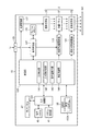
図2は、プロジェクター10の機能的構成を示すブロック図である。
プロジェクター10は、パーソナルコンピューターや各種画像プレーヤー等の外部の画像供給装置(図示略)にI/F(インターフェイス)部101を介して接続され、これらの画像供給装置から入力される入力画像をスクリーンSCに投射する。例えば、I/F部101は、USBインターフェイス、有線または無線LANインターフェイス、アナログ映像信号が入力されるVGA端子、デジタル映像信号が入力されるDVI(Digital Visual Interface)、NTSC、PAL、SECAM等のコンポジット映像信号が入力されるS映像端子、コンポジット映像信号が入力されるRCA端子、コンポーネント映像信号が入力されるD端子、HDMI(登録商標)規格に準拠したHDMIコネクター等を備え、上記の端子やコネクターを介して信号を入出力するインターフェイス回路を備えていてもよい。上記の画像供給装置としては、ビデオ再生装置、DVD再生装置、テレビチューナー装置、CATVのセットトップボックス、ビデオゲーム装置等の画像出力装置、パーソナルコンピューター等が挙げられる。本実施形態では、画像供給装置からI/F部101に、デジタル画像データが入力されるものとして説明する。このデジタル画像データには、画像データ自体とともに、当該デジタル画像データの画像フォーマットに関する情報が含まれる。
FIG. 2 is a block diagram illustrating a functional configuration of the
The
プロジェクター10は、大きく分けて光学的な画像の形成を行う投射部3(投射手段)と、この投射部3に入力される画像信号を電気的に処理する画像処理系とからなる。投射部3は、照明光学系31、光変調装置である液晶パネル32、及び投射光学系33から構成されている。照明光学系31は、キセノンランプ、超高圧水銀ランプ、LED(Light Emitting Diode)等からなる光源を備えている。また、照明光学系31は、光源が発した光を液晶パネル32に導くリフレクター及び補助リフレクターを備えていてもよく、投射光の光学特性を高めるためのレンズ群(図示略)、偏光板、或いは光源が発した光の光量を液晶パネル32に至る経路上で低減させる調光素子等を備えたものであってもよい。照明光学系31には、制御部103の制御に従って照明光学系31の光源を駆動する光源駆動部117が接続されている。
液晶パネル32は、後述する画像処理系からの信号を受けて、パネル面に画像を形成する。液晶パネル32は、カラーの投影を行うため、RGBの三原色に対応した3枚の液晶パネルからなる。そのため、照明光学系31からの光はRGBの3色の色光に分離され、各色光は対応する各液晶パネルに入射する。各液晶パネルを通過して変調された色光はクロスダイクロイックプリズム等の合成光学系によって合成され、投射光学系33に射出される。
The
The
投射光学系33は液晶パネル32で変調された入射光をスクリーンSC上に投射して結像させるためのレンズ群等を備えて構成される。この投射光学系33が有するレンズ群は、図1で説明したズーム調整レバー57の操作により移動して、ユーザーが望むズーム率で画像を拡大または縮小できる。また、フォーカス調整レバー55の操作によってスクリーンSC上に結蔵される画像のフォーカス調整が行われる。投射光学系33は、投射光量を絞る絞り等を調整するためのモーター類を備え、制御部103の制御に従って上記モーター等を駆動する投射光学系駆動部121が接続されている。
The projection optical system 33 includes a lens group for projecting incident light modulated by the
画像処理系は、プロジェクター10全体を統合的に制御する制御部103を中心に構成され、制御部103が処理するデータや制御部103が実行する制御プログラム105Aを記憶した記憶部105、リモコン受光部41、操作パネル45及びタッチパネル47を介した操作を検出する入力処理部123、入力画像データを処理する表示制御部107、表示制御部107から出力される画像信号に基づいて液晶パネル32を駆動して描画を行う光変調装置駆動部119を備えている。
The image processing system is configured around a
制御部103は、記憶部105に記憶された制御プログラムを読み出して実行することにより、プロジェクター10の各部を制御する。制御部103は、入力処理部123から入力される操作情報に基づいて、ユーザーが行った操作の内容を検出し、この操作に応じて表示制御部107、光変調装置駆動部119、投射光学系駆動部121及び光源駆動部117を制御して、スクリーンSCに画像を投射させる。
The
プロジェクター10は、制御部103の制御に従い、プロジェクター10の動作状態や設定状態に応じて操作パネル45のインジケーターランプを適宜点灯或いは点滅させ、操作パネル45のボタン類の操作を検出して操作情報を制御部103に出力する入力処理部123を備えている。
入力処理部123には、ユーザーが使用するリモコン(図示略)から送信される赤外線信号を受光するリモコン受光部41が接続されている。リモコン受光部41は、リモコンから受光した赤外線信号をデコードして入力処理部123に出力し、入力処理部123は、リモコンによる操作内容を示す操作情報を生成して制御部103に出力する。
また、入力処理部123は、所定周期でタッチパネル47への接触の有無を検出し、タッチパネル47への接触を検出した場合は、接触された位置(操作位置)を特定して、この操作位置を示す操作情報を制御部103に出力する。ここで、入力処理部123は、予めタッチパネル47の入力エリアに仮想的に設けられた座標系に基づき、操作位置の座標を制御部103に出力する。
Under the control of the
The
Further, the
I/F部101は、上述した外部の画像供給装置(図示略)に接続されている。
表示制御部107は、制御部103の制御に従って、画像供給装置からI/F部101を介して入力される入力画像信号に基づいて表示信号を生成し、光変調装置駆動部119に出力する。
表示制御部107は、I/F部101から入力される画像データを取得して、画像サイズ或いは解像度、静止画像か動画像であるかの別、動画像の場合はフレームレート等の画像データの属性を判定する。そして、表示制御部107は、入力画像をフレーム毎にフレームメモリー115に展開し、入力画像データの解像度が液晶パネル32の表示解像度と異なる場合には解像度変換処理を行い、リモコン(図示略)や操作パネル45の操作によりズームが指示された場合には拡大/縮小処理を行って、処理後の表示用のフレームをフレームメモリー115に描画する。その後、表示制御部107は、フレームメモリー115に展開したフレーム毎の画像を表示信号として光変調装置駆動部119に出力する。
The I /
The
The
制御部103は、記憶部105が記憶する制御プログラム105Aを実行することにより、入力検出部141、入力領域判定部142、操作量検出部143、及び補正制御部144の機能を実現する。
入力検出部141は、入力処理部123から入力される操作情報に基づいてタッチパネル47の操作を検出し、このタッチパネル47の操作に対応する処理(図5)を開始する。入力領域判定部142は、入力処理部123から入力される操作情報が示す操作位置の座標をもとに、操作位置が、タッチパネル47の入力エリアのどの領域に属するかを判定する。
The
The
図3は、タッチパネル47の入力エリアと投射画像との対応を示す説明図であり、(A)はスクリーンSCに矩形の投射画像201を投射する例を示し、(B)はスクリーンSCに三角形の投射画像211を投射する例を示す。
図3(A)及び(B)に示すように、タッチパネル47の入力エリア48は、スクリーンSCにプロジェクター10が投射する画像の形状に合わせて複数の領域に分割(区分)される。図3(A)の例ではスクリーンSCに表示される投射画像201が四角形であり、入力エリア48は4つの領域48A、48B、48C、48Dに分割される。なお、投射画像201は外形形状が矩形であるが、この矩形の枠内に表示される画像の内容は制限されず、静止画像であっても動画像であってもよい。また、各領域は入力エリア48を仮想的に分けるものであって、入力エリア48が現実に物理的に分割される必要はない。また、図3(B)の例ではスクリーンSC上の投射画像211が三角形であり、入力エリア48は3つの領域48P、48Q、48Rに分割される。
つまり、タッチパネル47の入力エリア48は、プロジェクター10が投射する投射画像の頂点の数と同数の領域に分割され、入力エリア48の各領域は投射画像の各頂点に対応づけられている。また、各領域の入力エリア48における位置と、これら各領域に対応する各頂点の投射画像における位置とは、対応している。例えば入力エリア48の左上に位置する領域48Aは、スクリーンSC上で左上に位置する頂点Aに対応している。このため、タッチパネル47と投射画像との対応関係が直感的に理解できる。
3A and 3B are explanatory diagrams showing the correspondence between the input area of the
As shown in FIGS. 3A and 3B, the
That is, the
図3(A)の例では、入力エリア48の4つの領域48A、48B、48C、48Dは、それぞれ、投射画像201の頂点A、B、C、Dに対応している。また、図3(B)の例では、入力エリア48の3つの領域48P、48Q、48Rは、それぞれ、投射画像211の頂点P、Q、Rに対応している。この入力エリア48の各領域における操作により、後述するように、対応する頂点が移動され、キーストーン補正(台形歪み補正)が行われる。
入力領域判定部142は、表示制御部107の処理により液晶パネル32に描画される投射画像の形状(頂点の数)と同数になるよう、タッチパネル47の入力エリアを複数の領域に分割する。具体的には、入力エリアに複数の領域を設定し、入力エリアの仮想の座標系に基づいて各領域に属する座標の範囲を決定し、記憶部105に記憶する。入力領域判定部142は、入力エリアにおける操作位置の座標を取得すると、取得した座標がどの領域に属するかを判定する。
In the example of FIG. 3A, the four
The input
図2に示す操作量検出部143は、入力処理部123から入力される操作情報に基づいて、タッチパネル47における操作の操作量及び操作方向を求める処理を行う。入力処理部123は、上述したように所定周期でタッチパネル47への接触を検出し、上記所定周期で接触の有無と接触位置とを示す操作情報を出力する。操作量検出部143は、所定周期の検出結果を示す操作情報について統計的処理を実行し、連続した操作が行われた場合に、この連続した操作を一つのまとまった操作として、操作量及び操作方向を求める。例えば、タッチパネル47に指を接触させたまま移動させる処理が行われた場合、入力処理部123は、所定周期で接触を検出し、そのとき検出した接触位置の座標を出力する。入力領域判定部142は、この入力処理部123から連続して入力される操作情報に基づき、操作位置の移動の軌跡を示すデータを生成し、このデータに基づいて、指を移動させる操作の方向、速度、及び操作開始から終了までの操作量を求める。
The operation
ここで、タッチパネル47における操作は、スクリーンSCに投射される投射画像のキーストーン補正に利用される。
図4は、タッチパネルの操作によりキーストーン補正を行う例を示す図であり、(A)は補正前の投射画像の状態を示し、(B)は操作例を示し、(C)は補正後の投射画像の状態を示す。
スクリーンSC上に結像する投射画像201は、プロジェクター10とスクリーンSCとの位置関係により歪み(いわゆる台形歪み)を生じる。図4(A)の例では、プロジェクター10の液晶パネル32に描画された矩形の画像が、スクリーンSC上では左上に伸びた四角形の投射画像201となっている。
プロジェクター10は、液晶パネル32に描画する画像を変形させることにより、スクリーンSC上で本来の形状の画像が結像するよう補正するキーストーン補正を実行できる。具体的には、図4(A)の投射画像201は長方形の画像が左上方向に伸びるように変形しており、頂点Aが、本来の位置よりも左上に移動している。本来の位置とは、スクリーンSC上に結像する画像が、I/F部101を介してプロジェクター10に入力された画像の形状と同じ形状になった場合の位置を指す。例えばプロジェクター10をスクリーンSCに正対する位置に設置し、プロジェクター10が投射する投射光の進行方向が、スクリーンSCに対して上下方向および左右方向のいずれにおいても垂直である場合には、歪みのない本来の画像がスクリーンSCに結像する。
Here, the operation on the
4A and 4B are diagrams illustrating an example in which keystone correction is performed by operating the touch panel. FIG. 4A illustrates a state of a projected image before correction, FIG. 4B illustrates an operation example, and FIG. The state of a projection image is shown.
The projected
The
ここで、タッチパネル47において、頂点Aに対応する領域48Aで、図中矢印で示すように右下方向のドラッグ操作を実行すると、この操作に応じて液晶パネル32の画像が図4(B)に示すように変形される。
まず、入力エリア48の領域48Aに対する接触操作が検出されると、制御部103により、この領域48Aに対応する頂点Aが、移動対象の頂点として選択される。
続いて、図4(B)に示すように、投射画像201の頂点Aが、図4(B)の矢印で示す操作方向に、その操作量に対応する分だけ移動するように、画像が変形される。このように液晶パネル32に描画された画像を変形すると、スクリーンSCで結像する投射画像201の頂点Aも、本来の位置A´に移動する。これにより、スクリーンSC上の画像は、本来の矩形の投射画像201となる。
また、図4(B)の例では、最初のタッチパネル47への操作が領域48Aで行われるため、移動対象の頂点として頂点Aが選択され、投射画像201の頂点B、C、Dは移動しない。
Here, when a drag operation in the lower right direction is executed on the
First, when a touch operation on the
Subsequently, as shown in FIG. 4B, the image is deformed so that the vertex A of the
In the example of FIG. 4B, since the first operation on the
このように、プロジェクター10のキーストーン補正機能では、最初にタッチパネル47への操作が行われると、この操作がなされた領域が特定され、投射画像において対応する頂点が移動対象の頂点として選択される。この状態では、最初に操作された領域以外の領域に対する操作が行われても、いったん選択された頂点が移動するように画像が変形する。例えば、領域48Aが操作されて頂点Aが移動対象に選択された場合、次のタッチパネル47への操作が領域48B、48C、48Dに及ぶ操作であっても、頂点Aが移動される。このため、移動対象の領域が選択された後は入力エリア48全体を使って頂点の移動方向及び移動量を入力でき、操作性が高い。
また、図4(B)に例示したように、最初の操作が単なる接触操作でなく、手指を入力エリア48に接触させたまま移動するドラッグ操作であった場合、最初の操作で選択された頂点を、この最初の操作の操作方向および操作量に応じて移動させるよう画像を変形することもできる。この場合、1回の操作で移動対象の頂点を指定し、移動方向及び移動量を入力できる。
As described above, in the keystone correction function of the
Further, as illustrated in FIG. 4B, when the first operation is not a simple contact operation but a drag operation in which the finger is moved while being in contact with the
図2の補正制御部144(補正手段)は、図4(C)に示したように、入力領域判定部142により判定された領域に対応する頂点を、移動対象の頂点として選択する。そして、補正制御部144は、操作量検出部143が求めた操作方向および操作量に対応する分だけ、移動対象の頂点を移動させるように画像を変形させる処理を行う。詳細には、画像を変形させるためのパラメーターを生成し、このパラメーターに従って表示制御部107を制御して画像を変形させ、変形させた画像の表示信号を光変調装置駆動部119に出力させる。
これにより、タッチパネル47に対する操作によってスクリーンSC上の投射画像を変形させ、台形歪みを補正できる。
As illustrated in FIG. 4C, the correction control unit 144 (correction unit) in FIG. 2 selects a vertex corresponding to the area determined by the input
Thereby, the projection image on the screen SC can be deformed by an operation on the
図5は、プロジェクター10の動作を示すフローチャートである。
プロジェクター10がスクリーンSCへの画像の投射を開始し(ステップS11)、リモコン(図示略)または操作パネル45の操作によってキーストーン補正の開始が指示されると(ステップS12)、制御部103はタッチパネル47が操作されるまで待機する(ステップS13)。
タッチパネル47が操作され、操作情報が入力処理部123から制御部103に入力されると、制御部103は入力検出部141の機能によって操作を検出する(ステップS13;Yes)。制御部103は、入力領域判定部142の機能によって、タッチパネル47の操作位置に対応する領域を判定する(ステップS14)。制御部103は、補正制御部144の機能によって、投射中の画像の外形形状において操作された領域に対応する頂点を、移動対象の頂点に設定する(ステップS15)。
FIG. 5 is a flowchart showing the operation of the
When the
When the
ここで、ステップS13で検出したタッチパネル47への操作がドラッグ操作でない場合には、制御部103はドラッグ操作を待機する(ステップS16;No)。タッチパネル47へのドラッグ操作が行われた場合(ステップS16;Yes)、或いは、最初のタッチパネル47への操作がドラッグ操作であった場合、制御部103は、操作量検出部143の機能によって、ドラッグ操作の操作方向と操作量を検出する(ステップS17)。
If the operation on the
次いで、制御部103は、補正制御部144の機能により、操作量検出部143が検出した操作方向と操作量に応じて移動対象の頂点が移動するように画像を変形するパラメーターを生成し、このパラメーターに従って表示制御部107を制御して、画像を変形させる(ステップS18)。これにより、スクリーンSC上には補正後の画像が投射される。
その後、リモコン(図示略)または操作パネル45の操作によってキーストーン補正を完了する指示が入力された場合には(ステップS19;Yes)、制御部103は本処理を終了して通常の投射動作に戻る。また、キーストーン補正を終了する操作が行われるまでは(ステップS19;No)、制御部103はステップS13に戻り、タッチパネル47の操作を受け付ける。
Next, the
Thereafter, when an instruction to complete keystone correction is input by operating the remote controller (not shown) or the operation panel 45 (step S19; Yes), the
以上説明したように、本発明を適用した実施形態に係るプロジェクター10によれば、スクリーンSCに、頂点を有する形状の投射画像を投射する投射部3と、所定の入力エリア48を有するタッチパネル47とを備え、制御部103は、補正制御部144により、タッチパネル47の操作に応じて、投射部3により投射される投射画像を変形させる機能を備え、タッチパネル47の入力エリア48が複数の領域48A〜48Dに区分され、これら各領域48A〜48Dのうち少なくとも一つが、投射画像のいずれかの頂点に対応づけられ、補正制御部144は、タッチパネル47の入力エリア48で操作がなされた場合に、操作された領域に対応する投射画像の頂点を移動対象として選択し、この移動対象の頂点がタッチパネル47の操作に応じた方向及び量だけ移動するように投射画像を変形させる。これにより、台形歪み補正処理で投射画像を変形させる場合に、投射画像の複数の頂点のうち移動対象の頂点を選択するための操作と、選択された頂点の移動方向及び量を指定する操作とを、タッチパネル47によって簡単に行うことができ、例えば投射画像を見ながらでも指一本で簡単に実行できる。これにより、投射画像を変形させるための入力操作を、直感的に、かつ手軽に行うことができる。
As described above, according to the
また、タッチパネル47の入力エリア48は投射画像の頂点と同数の領域48A〜48Dに区分され、これら各領域48A〜48Dが投射画像の各頂点に対応づけられているので、入力エリア48の各領域と投射画像の頂点との対応関係がわかりやすい。このため、より直感的で簡単な入力操作を実現できる。
また、タッチパネル47によって、台形歪み補正機能により投射画像を変形させるための入力操作を、より直感的に、かつ手軽に行うことができる。
また、プロジェクター10がスクリーンSCに画像を投射中であっても操作しやすい場所にタッチパネル47を設けたことにより、投射画像を見ながら、直感的で簡単な操作によって投射画像を変形させるための入力操作を行うことができる。ここで、タッチパネル47は、プロジェクター10の筐体11本体の上面に限らず、スクリーンSCの反対側の側面すなわち投射用開口部11Aの反対側の面に設けてもよい。
また、ポインティングデバイスとして、ユーザーの手指による接触操作を検出するタッチパネル47を設けたことにより、ユーザーの手指により、投射画像を変形させる処理を行う場合に移動対象とする頂点を選択するための操作と、選択された頂点の移動方向及び移動量を指定する操作とを、簡単に行うことができる。
The
In addition, an input operation for deforming a projection image by the trapezoidal distortion correction function can be performed more intuitively and easily by the
Further, by providing the
In addition, by providing a
なお、上述した実施形態は本発明を限定するものではなく、上記実施形態とは異なる態様として本発明を適用することも可能である。例えば、上記実施形態では、スクリーンSCに矩形の投射画像や三角形の投射画像を投射する場合について説明したが、本発明はこれに限定されるものではなく、より頂点が多い多角形の投射画像を投射する場合にも適用可能であるし、投射画像の外形(枠)が直線で構成されない場合においても、頂点を有する形状の投射画像を投射する場合には適用可能である。また、上記実施形態では、入力エリア48がスクリーンSC上の投射画像の頂点と同数の領域に区分される例について説明したが、本発明はこれに限定されるものではなく、入力エリア48を分割した領域のうち少なくとも一つの領域が、投射画像の頂点に対応づけられていればよい。このため、例えば、投射画像の頂点より多くの領域に分割されていてもよいし、入力エリア48の領域が投射画像の頂点よりも少ない数であってもよい。
In addition, embodiment mentioned above does not limit this invention, It is also possible to apply this invention as an aspect different from the said embodiment. For example, in the above-described embodiment, the case where a rectangular projection image or a triangular projection image is projected onto the screen SC has been described. However, the present invention is not limited to this, and a polygonal projection image with more vertices is used. The present invention can be applied to the case of projecting, and can be applied to the case of projecting a projected image having a vertex even when the outer shape (frame) of the projected image is not configured by a straight line. In the above embodiment, the example in which the
また、上記実施形態では、投射部3において光源が発した光を変調する変調手段として、RGBの各色に対応した3枚の透過型または反射型の液晶パネル32を用いた構成を例に挙げて説明したが、本発明はこれに限定されるものではなく、例えば、1枚の液晶パネルとカラーホイールを組み合わせた方式、3枚のデジタルミラーデバイス(DMD)を用いた方式、1枚のデジタルミラーデバイスとカラーホイールを組み合わせた方式等により構成してもよい。ここで、変調手段として1枚のみの液晶パネルまたはDMDを用いる場合には、クロスダイクロイックプリズム等の合成光学系に相当する部材は不要である。また、液晶パネル及びDMD以外にも、光源が発した光を変調可能な構成であれば問題なく採用できる。
また、上記実施形態では、フォーカス調整レバー55やズーム調整レバー57の操作により手動でフォーカス調整及びズーム調整が行われる構成を例に挙げて説明したが、本発明はこれに限定されるものではない。
さらに、上記実施形態では、ポインティングデバイスとしてタッチパネル47を筐体11の上面に設けた構成を例に挙げて説明したが、ポインティングデバイスとしてはペンタブレットやデジタイザーを用いることもでき、液晶表示画面に重畳配置されたタッチパネルを用いてもよく、その他、入力エリアが規定されたポインティングデバイスであれば具体的な構成は任意である。また、タッチパネル47の設置位置、サイズ及び形状などについても任意であり、例えば、プロジェクター10に外部接続された入力デバイスにタッチパネル47を設けてもよいし、リモコン受光部41に対し赤外線信号を送信するリモコン(図示略)に、タッチパネル47を設けてもよい。
Moreover, in the said embodiment, the structure using the three transmissive | pervious or reflective
In the above-described embodiment, the configuration in which focus adjustment and zoom adjustment are manually performed by operating the
Furthermore, in the above-described embodiment, the configuration in which the
また、上記実施形態において記憶部105が記憶していた制御プログラム105Aを、プロジェクター10が通信ネットワークを介して接続された他の装置からダウンロードして実行しても良いし、可搬型の記録媒体に制御プログラム105Aを記録して、この記録媒体から上記各プログラムを読み取って実行する構成としても良い。
さらに、図2に示したプロジェクター10の各機能部は機能的構成を示すものであって、具体的な実装形態は特に制限されない。つまり、必ずしも各機能部に個別に対応するハードウェアが実装される必要はなく、一つのプロセッサーがプログラムを実行することで複数の機能部の機能を実現する構成とすることも勿論可能である。また、上記実施形態においてソフトウェアで実現されている機能の一部をハードウェアで実現してもよく、あるいは、ハードウェアで実現されている機能の一部をソフトウェアで実現してもよい。その他、プロジェクター10の具体的な細部構成について、本発明の趣旨を逸脱しない範囲で任意に変更可能である。
Further, the
Furthermore, each functional unit of the
3…投射部(投射手段)、10…プロジェクター、11…筐体(プロジェクター本体)、32…液晶パネル、47…タッチパネル(ポインティングデバイス)、48…入力エリア、48A、48B、48C、48D…領域、48P、48Q、48R…領域、101…I/F部、103…制御部、105…記憶部、105A…制御プログラム、107…表示制御部、115…フレームメモリー、123…入力処理部、141…入力検出部、142…入力領域判定部、143…操作量検出部、144…補正制御部(補正手段)、201、211…投射画像、A、B、C、D、P、Q、R…頂点、SC…スクリーン(投射面)。
DESCRIPTION OF
Claims (6)
所定の入力エリアを有するポインティングデバイスと、
前記ポインティングデバイスの操作に応じて、前記投射手段により投射される前記投射画像を変形させる補正手段と、を備え、
前記ポインティングデバイスは、前記入力エリアが複数の領域に区分され、これら各領域のうち少なくとも一つが、前記投射画像のいずれかの頂点に対応づけられ、
前記補正手段は、前記ポインティングデバイスの前記入力エリアで操作がなされた場合に、操作された領域に対応する前記投射画像の頂点を移動対象として選択し、この移動対象の頂点が前記ポインティングデバイスの操作に応じた方向及び量だけ移動するように前記投射画像を変形させること、
を特徴とするプロジェクター。 Projection means for projecting a projection image having a vertex on the projection surface;
A pointing device having a predetermined input area;
A correction unit that deforms the projection image projected by the projection unit in response to an operation of the pointing device;
In the pointing device, the input area is divided into a plurality of regions, and at least one of these regions is associated with any vertex of the projection image,
When the operation is performed in the input area of the pointing device, the correction unit selects a vertex of the projection image corresponding to the operated area as a movement target, and the movement target vertex is an operation of the pointing device. Deforming the projected image so as to move in a direction and amount according to
Projector.
前記ポインティングデバイスの前記入力エリアの領域のうち少なくとも一つを、前記投射画像のいずれかの頂点に対応づけておき、
前記ポインティングデバイスの前記入力エリアで操作がなされた場合に、操作された領域に対応する前記投射画像の頂点を移動対象として選択し、
移動対象として選択された頂点が前記ポインティングデバイスの操作に応じた方向及び量だけ移動するように前記投射画像を変形させること、
を特徴とするプロジェクターの制御方法。 A control method for a projector comprising a pointing device having an input area divided into a plurality of regions, and projecting a projected image having a vertex on a projection surface,
At least one area of the input area of the pointing device is associated with any vertex of the projection image,
When an operation is performed in the input area of the pointing device, a vertex of the projection image corresponding to the operated area is selected as a movement target,
Deforming the projection image so that a vertex selected as a movement target moves by a direction and an amount corresponding to an operation of the pointing device;
A projector control method characterized by the above.
Priority Applications (1)
| Application Number | Priority Date | Filing Date | Title |
|---|---|---|---|
| JP2011059065A JP2012194424A (en) | 2011-03-17 | 2011-03-17 | Projector and control method for projector |
Applications Claiming Priority (1)
| Application Number | Priority Date | Filing Date | Title |
|---|---|---|---|
| JP2011059065A JP2012194424A (en) | 2011-03-17 | 2011-03-17 | Projector and control method for projector |
Publications (1)
| Publication Number | Publication Date |
|---|---|
| JP2012194424A true JP2012194424A (en) | 2012-10-11 |
Family
ID=47086370
Family Applications (1)
| Application Number | Title | Priority Date | Filing Date |
|---|---|---|---|
| JP2011059065A Withdrawn JP2012194424A (en) | 2011-03-17 | 2011-03-17 | Projector and control method for projector |
Country Status (1)
| Country | Link |
|---|---|
| JP (1) | JP2012194424A (en) |
Cited By (8)
| Publication number | Priority date | Publication date | Assignee | Title |
|---|---|---|---|---|
| JP2015154173A (en) * | 2014-02-13 | 2015-08-24 | セイコーエプソン株式会社 | control device, projector, control method, and control program |
| JP2015187755A (en) * | 2014-03-26 | 2015-10-29 | キヤノン株式会社 | Image processing apparatus, image processing method, and program |
| CN105025239A (en) * | 2014-04-16 | 2015-11-04 | 何文学 | Mobile intelligent touch screen projector |
| JP2016042657A (en) * | 2014-08-18 | 2016-03-31 | キヤノン株式会社 | Projection type display device |
| JP2016065995A (en) * | 2014-09-25 | 2016-04-28 | キヤノン株式会社 | Projection type image display device and method of controlling the same |
| US9720547B2 (en) | 2013-03-19 | 2017-08-01 | Samsung Electronics Co., Ltd. | Optical apparatus including non-electric type touch panel |
| JP2019078845A (en) * | 2017-10-23 | 2019-05-23 | セイコーエプソン株式会社 | Projector and method for controlling projector |
| CN114125411A (en) * | 2021-12-01 | 2022-03-01 | 深圳市火乐科技发展有限公司 | Projection equipment correction method and device, storage medium and projection equipment |
-
2011
- 2011-03-17 JP JP2011059065A patent/JP2012194424A/en not_active Withdrawn
Cited By (9)
| Publication number | Priority date | Publication date | Assignee | Title |
|---|---|---|---|---|
| US9720547B2 (en) | 2013-03-19 | 2017-08-01 | Samsung Electronics Co., Ltd. | Optical apparatus including non-electric type touch panel |
| US10254899B2 (en) | 2013-03-19 | 2019-04-09 | Samsung Electronics Co., Ltd. | Optical apparatus including non-electric type touch panel |
| JP2015154173A (en) * | 2014-02-13 | 2015-08-24 | セイコーエプソン株式会社 | control device, projector, control method, and control program |
| JP2015187755A (en) * | 2014-03-26 | 2015-10-29 | キヤノン株式会社 | Image processing apparatus, image processing method, and program |
| CN105025239A (en) * | 2014-04-16 | 2015-11-04 | 何文学 | Mobile intelligent touch screen projector |
| JP2016042657A (en) * | 2014-08-18 | 2016-03-31 | キヤノン株式会社 | Projection type display device |
| JP2016065995A (en) * | 2014-09-25 | 2016-04-28 | キヤノン株式会社 | Projection type image display device and method of controlling the same |
| JP2019078845A (en) * | 2017-10-23 | 2019-05-23 | セイコーエプソン株式会社 | Projector and method for controlling projector |
| CN114125411A (en) * | 2021-12-01 | 2022-03-01 | 深圳市火乐科技发展有限公司 | Projection equipment correction method and device, storage medium and projection equipment |
Similar Documents
| Publication | Publication Date | Title |
|---|---|---|
| JP6064319B2 (en) | Projector and projector control method | |
| JP5849560B2 (en) | Display device, projector, and display method | |
| JP6088127B2 (en) | Display device, display device control method, and program | |
| JP2012194424A (en) | Projector and control method for projector | |
| JP5927845B2 (en) | Display device, display device control method, and program | |
| JP5585505B2 (en) | Image supply apparatus, image display system, image supply apparatus control method, image display apparatus, and program | |
| US10989993B2 (en) | Control device for correcting projection image, projection system, method of controlling same, and storage medium | |
| JP6141596B2 (en) | Display device, display system, and data supply method for display device | |
| JP5874401B2 (en) | Display device, projector, display system, and device switching method | |
| JP5488082B2 (en) | Information recognition system and control method thereof | |
| JP2014052930A (en) | Display device and control method of display device | |
| JP6307852B2 (en) | Image display device and method for controlling image display device | |
| US20170103687A1 (en) | Projector and control method for projector | |
| JP2015031817A (en) | Projector, and control method of projector | |
| JP6051828B2 (en) | Display device and control method of display device | |
| JP2017182110A (en) | Display system, display device, information processor, and information processing method | |
| JP6269801B2 (en) | Projector and projector control method | |
| JP6117470B2 (en) | Display device, projector, image display method, and display system | |
| JP6273671B2 (en) | Projector, display system, and projector control method | |
| JP2012181721A (en) | Position input device, projector, control method for projector, and display system | |
| JP2018022013A (en) | Display device, display system, and method for controlling display device | |
| JP2018132769A (en) | Image display device, and control method of image display device | |
| JP6255810B2 (en) | Display device and control method of display device | |
| JP6056447B2 (en) | Display device and control method of display device | |
| JP6145963B2 (en) | Projector, display system, and projector control method |
Legal Events
| Date | Code | Title | Description |
|---|---|---|---|
| A300 | Application deemed to be withdrawn because no request for examination was validly filed |
Free format text: JAPANESE INTERMEDIATE CODE: A300 Effective date: 20140603 |