JP2012194370A - Lens barrel and imaging apparatus - Google Patents

Lens barrel and imaging apparatus Download PDF

Info

Publication number
JP2012194370A
JP2012194370A JP2011058213A JP2011058213A JP2012194370A JP 2012194370 A JP2012194370 A JP 2012194370A JP 2011058213 A JP2011058213 A JP 2011058213A JP 2011058213 A JP2011058213 A JP 2011058213A JP 2012194370 A JP2012194370 A JP 2012194370A
Authority
JP
Japan
Prior art keywords
holding frame
corrugated spring
holding
lens barrel
spring
Prior art date
Legal status (The legal status is an assumption and is not a legal conclusion. Google has not performed a legal analysis and makes no representation as to the accuracy of the status listed.)
Pending
Application number
JP2011058213A
Other languages
Japanese (ja)
Other versions
JP2012194370A5 (en
Inventor
Koji Sawada
功二 澤田
Yasuhiro Kanamitsu
容大 金満
Current Assignee (The listed assignees may be inaccurate. Google has not performed a legal analysis and makes no representation or warranty as to the accuracy of the list.)
Nikon Corp
Original Assignee
Nikon Corp
Priority date (The priority date is an assumption and is not a legal conclusion. Google has not performed a legal analysis and makes no representation as to the accuracy of the date listed.)
Filing date
Publication date
Application filed by Nikon Corp filed Critical Nikon Corp
Priority to JP2011058213A priority Critical patent/JP2012194370A/en
Publication of JP2012194370A publication Critical patent/JP2012194370A/en
Publication of JP2012194370A5 publication Critical patent/JP2012194370A5/ja
Pending legal-status Critical Current

Links

Images

Abstract

PROBLEM TO BE SOLVED: To provide a lens barrel and an imaging apparatus which suppress a local large load.SOLUTION: The lens barrel includes: a first holding frame for holding an optical system; a second holding frame for holding the first holding frame; a corrugated leaf-spring which is arranged between the first holding frame and the second holding frame; and a positioning portion which positions the first holding frame to the second holding frame by pressing the first holding frame to the corrugated leaf-spring.

Description

本発明は、レンズ鏡筒及び撮像装置に関する。   The present invention relates to a lens barrel and an imaging apparatus.

特許文献1には、レンズ鏡筒に設けられた光学系の位置を調整する技術が開示されている。   Patent Document 1 discloses a technique for adjusting the position of an optical system provided in a lens barrel.

特開2007−298864号公報JP 2007-298864 A

光学系を保持する保持枠の位置を、複数の調整ネジとコイルバネとにより調整する場合がある。しかしながら、このような部材により保持枠の位置を調整すると、保持枠に対して局所的に大きな負荷がかかるおそれがある。   In some cases, the position of the holding frame that holds the optical system is adjusted by a plurality of adjustment screws and coil springs. However, when the position of the holding frame is adjusted by such a member, a large load may be locally applied to the holding frame.

そこで本発明は上記の課題に鑑みてなされたものであり、局所的に大きな負荷がかかることが抑制されたレンズ鏡筒及び撮像装置を提供することを目的とする。   Accordingly, the present invention has been made in view of the above-described problems, and an object thereof is to provide a lens barrel and an imaging apparatus in which a large load is prevented from being locally applied.

本発明は、以下のような解決手段により上記課題を解決する。尚、理解を容易にするために本発明の一実施例を示す図面に対応する符号を付して説明するが、これに限定されるものではない。   The present invention solves the above problems by the following means. For ease of understanding, the description will be given with reference numerals corresponding to the drawings showing an embodiment of the present invention, but the present invention is not limited to this.

本実施例のレンズ鏡筒は、光学系(121b)を保持する第1保持枠(30)と、前記第1保持枠を保持する第2保持枠(10)と、前記第1保持枠と前記第2保持枠との間に配置された波板バネ(20)と、前記第1保持枠を前記波板バネに向けて押すことにより前記第1保持枠を前記第2保持枠に対して位置決めする位置決め部(11a、11b)と、を備えている。   The lens barrel of the present embodiment includes a first holding frame (30) that holds the optical system (121b), a second holding frame (10) that holds the first holding frame, the first holding frame, and the Positioning the first holding frame relative to the second holding frame by pushing the corrugated spring (20) disposed between the second holding frame and the first holding frame toward the wave spring. Positioning portions (11a, 11b).

撮像装置は、上記のレンズ鏡筒を備えている。   The imaging device includes the lens barrel described above.

本発明によれば、負荷が局所的に集中することが抑制されたレンズ鏡筒及び撮像装置を提供できる。   According to the present invention, it is possible to provide a lens barrel and an imaging apparatus in which the load is suppressed from being concentrated locally.

図1は、レンズ鏡筒の内部構成を示した図である。FIG. 1 is a diagram showing an internal configuration of a lens barrel. 図2は、保持枠の断面図である。FIG. 2 is a cross-sectional view of the holding frame. 図3は、光軸を含む平面での保持枠の断面図である。FIG. 3 is a cross-sectional view of the holding frame in a plane including the optical axis. 図4は、波板バネ周辺の構造を示した拡大図である。FIG. 4 is an enlarged view showing the structure around the corrugated spring. 図5は、保持枠と波板バネとの分解斜視図である。FIG. 5 is an exploded perspective view of the holding frame and the corrugated spring. 図6A、6Bは、波板バネの変形の説明図である。6A and 6B are explanatory diagrams of deformation of the corrugated spring. 図7は、本実施例に対する比較例の説明図である。FIG. 7 is an explanatory diagram of a comparative example with respect to the present embodiment. 図8は、本実施例の変形例の説明図である。FIG. 8 is an explanatory diagram of a modification of the present embodiment.

以下、発明の実施の形態を通じて本発明を説明するが、以下の実施形態は特許請求の範囲に関わる発明を限定するものではない。また、実施形態の中で説明されている特徴の組み合わせの全てが発明の解決手段であるとは限らない。   Hereinafter, the present invention will be described through embodiments of the invention, but the following embodiments do not limit the invention according to the claims. In addition, not all combinations of features described in the embodiments are solving means of the invention.

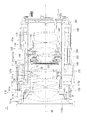
図1は、レンズ鏡筒1の内部構成を示している。レンズ鏡筒1は、光学装置の一例である。図1において、詳しくは後述する保持枠10、30をハッチングして示している。図1に示すように、レンズ鏡筒1は、第1から4のレンズ群を備える。レンズ111a〜111dは、第1レンズ群に相当する。レンズ121a、121bは第2レンズ群に相当する。レンズ131a、131bは第3レンズ群に相当する。レンズ141a、141bは第4レンズ群に相当する。レンズ111aは保持枠112aに保持され、レンズ111b〜111dは保持枠112bに保持されている。レンズ121aは、保持枠122に保持されている。レンズ121bは保持枠30に保持されている。レンズ131a、131bは保持枠132に保持され、レンズ141a、141bは保持枠142に保持されている。   FIG. 1 shows the internal configuration of the lens barrel 1. The lens barrel 1 is an example of an optical device. In FIG. 1, holding frames 10 and 30 described later in detail are hatched. As shown in FIG. 1, the lens barrel 1 includes first to fourth lens groups. The lenses 111a to 111d correspond to a first lens group. The lenses 121a and 121b correspond to the second lens group. The lenses 131a and 131b correspond to a third lens group. The lenses 141a and 141b correspond to a fourth lens group. The lens 111a is held by the holding frame 112a, and the lenses 111b to 111d are held by the holding frame 112b. The lens 121a is held by the holding frame 122. The lens 121b is held by the holding frame 30. The lenses 131a and 131b are held by the holding frame 132, and the lenses 141a and 141b are held by the holding frame 142.

レンズ鏡筒1は、カメラボディ等の撮像装置に固定される固定筒140と、固定筒140に収容されたカム筒150とを備えている。カム筒150は、固定筒140の内周面と光軸OP周りに回転自在に嵌合している。カム筒150の内周側には、第1〜第4レンズ群と、保持枠112a、112b、132、142とが配置されている。   The lens barrel 1 includes a fixed cylinder 140 that is fixed to an imaging apparatus such as a camera body, and a cam cylinder 150 that is accommodated in the fixed cylinder 140. The cam cylinder 150 is fitted to the inner peripheral surface of the fixed cylinder 140 so as to be rotatable around the optical axis OP. On the inner peripheral side of the cam barrel 150, first to fourth lens groups and holding frames 112a, 112b, 132, 142 are disposed.

保持枠112b、122、30、132、142は、それぞれ、連結部材116、126、保持枠10、連結部材136、146に結合されている。連結部材116、126、136、146、保持枠10は、カム筒150の内周面に、光軸周りに回転自在に嵌合した円筒状の部材である。尚、連結部材126は、保持枠10の内周側に連結されている。保持枠112aは、保持枠112bに結合されている。   The holding frames 112b, 122, 30, 132, 142 are coupled to the connecting members 116, 126, the holding frame 10, and the connecting members 136, 146, respectively. The connecting members 116, 126, 136, and 146 and the holding frame 10 are cylindrical members that are fitted to the inner peripheral surface of the cam cylinder 150 so as to be rotatable around the optical axis. The connecting member 126 is connected to the inner peripheral side of the holding frame 10. The holding frame 112a is coupled to the holding frame 112b.

保持枠10、136、146の、カム筒150の内周面に当接する外周面には、それぞれカムピン11、138、148が結合されている。また、連結部材116にも、図示していないがカムピンが結合されている。一方、カム筒150には、カムピン11等がそれぞれ挿入される複数のカム溝が形成されている。カム筒150が光軸OP周りに回転することにより、カムピン11等がカム溝から光軸OPの方向に押され、保持枠10、連結部材136、146が光軸OPの方向に移動する。   Cam pins 11, 138 and 148 are coupled to the outer peripheral surfaces of the holding frames 10, 136 and 146 which are in contact with the inner peripheral surface of the cam cylinder 150. Further, although not shown, a cam pin is also coupled to the connecting member 116. On the other hand, the cam cylinder 150 is formed with a plurality of cam grooves into which the cam pins 11 and the like are respectively inserted. As the cam cylinder 150 rotates around the optical axis OP, the cam pin 11 and the like are pushed from the cam groove in the direction of the optical axis OP, and the holding frame 10 and the connecting members 136 and 146 move in the direction of the optical axis OP.

第2レンズ群の外周側には、フォーカス環170が配されている。フォーカス環170は、光軸周りに回転自在に固定筒140及び第1外固定筒200と嵌合している。第4レンズ群の外周側には、ズーム環180が配されている。ズーム環180は、光軸周りに回転自在に第1外固定筒200及び第2外固定筒201と嵌合している。   A focus ring 170 is disposed on the outer peripheral side of the second lens group. The focus ring 170 is fitted to the fixed cylinder 140 and the first outer fixed cylinder 200 so as to be rotatable around the optical axis. A zoom ring 180 is disposed on the outer peripheral side of the fourth lens group. The zoom ring 180 is fitted to the first outer fixed cylinder 200 and the second outer fixed cylinder 201 so as to be rotatable around the optical axis.

第2レンズ群の一のレンズ121bは、光軸OPの位置を調整可能な調芯レンズである。詳細は後述するが、調芯レンズとしてのレンズ121bを保持する保持枠30の外周面には、光軸OPと直交する方向(以下、径方向と称する)に進退可能な複数の調整ネジ11a、11bと、が当接されている。   The lens 121b in the second lens group is a centering lens capable of adjusting the position of the optical axis OP. As will be described in detail later, a plurality of adjustment screws 11a that can advance and retreat in a direction orthogonal to the optical axis OP (hereinafter referred to as a radial direction) are provided on the outer peripheral surface of the holding frame 30 that holds the lens 121b as an alignment lens. 11b.

フォーカス環170には、貫通孔175が形成されている。固定筒140にも、貫通孔175に対応する位置に不図示の貫通孔が形成されている。これら貫通孔は、調整ネジ11a、11bを調整するための工具を挿入するためのものである。   A through hole 175 is formed in the focus ring 170. The fixed cylinder 140 also has a through hole (not shown) at a position corresponding to the through hole 175. These through holes are for inserting tools for adjusting the adjusting screws 11a and 11b.

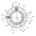
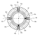
図2は、保持枠10、30の断面図である。保持枠30は、レンズ121bを保持している。保持枠30は、レンズ121bの光軸OPの方向から見た場合に略円形である。保持枠10は、保持枠30の外周側に配置されている。保持枠10、30の間に波板バネ20が配置されている。   FIG. 2 is a cross-sectional view of the holding frames 10 and 30. The holding frame 30 holds the lens 121b. The holding frame 30 is substantially circular when viewed from the direction of the optical axis OP of the lens 121b. The holding frame 10 is disposed on the outer peripheral side of the holding frame 30. A corrugated spring 20 is disposed between the holding frames 10 and 30.

保持枠10には、調整ネジ11a、11bが保持されている。保持枠10には、調整ネジ11a、11bがそれぞれ螺合したネジ孔12a、12bが形成されている。調整ネジ11a、11bには、それぞれレンチを挿入可能な穴が設けられている。調整ネジ11a、11bは、保持枠10の内側に突出している。調整ネジ11a、11bは、それぞれネジ孔12a、12bとの螺合量を調整することにより、保持枠10からの突出量を調整できる。調整ネジ11a、11bは、レンズ121bの径方向、即ち保持枠30へ進退可能に保持枠10に支持されている。   Adjustment screws 11 a and 11 b are held on the holding frame 10. The holding frame 10 is formed with screw holes 12a and 12b into which adjustment screws 11a and 11b are respectively screwed. Each of the adjustment screws 11a and 11b is provided with a hole into which a wrench can be inserted. The adjustment screws 11 a and 11 b protrude inside the holding frame 10. The adjustment screws 11a and 11b can adjust the amount of protrusion from the holding frame 10 by adjusting the amount of screwing with the screw holes 12a and 12b, respectively. The adjustment screws 11a and 11b are supported by the holding frame 10 so as to be movable in and out of the radial direction of the lens 121b, that is, the holding frame 30.

調整ネジ11a、11bは、図2に示すように光軸OP周りに略90度の間隔を有して配置されているが、このような配置に限定されない。調整ネジ11aの軸線Aaと調整ネジ11bの軸線Abとは略直交している。また、図2においては、レンズ121bの光軸OPが軸線Aa、Abの交点を通過しているが、調整ネジ11a、11bの位置を調整することにより、光軸OPが軸線Aa、Abの交点からずれる場合がある。   The adjustment screws 11a and 11b are arranged with an interval of about 90 degrees around the optical axis OP as shown in FIG. 2, but the arrangement is not limited to such an arrangement. The axis Aa of the adjusting screw 11a and the axis Ab of the adjusting screw 11b are substantially orthogonal. In FIG. 2, the optical axis OP of the lens 121b passes through the intersection of the axes Aa and Ab. However, by adjusting the position of the adjusting screws 11a and 11b, the optical axis OP becomes the intersection of the axes Aa and Ab. It may be out of place.

調整ネジ11a、11bは、それぞれ、保持枠30の外周面に形成された被押圧面32a、32bに当接している。被押圧面32a、32bは、光軸OPの方向から見て平面である。   The adjusting screws 11a and 11b are in contact with the pressed surfaces 32a and 32b formed on the outer peripheral surface of the holding frame 30, respectively. The pressed surfaces 32a and 32b are planes when viewed from the direction of the optical axis OP.

レンズ121bの光軸OPの方向から見て、保持枠30は、調整ネジ11a、11bと、波板バネ20とにより挟まれている。即ち、波板バネ20は、軸線Aa、Abの間の領域であって光軸OPを介して調整ネジ11a、11bと対向する領域に配置されている。   When viewed from the direction of the optical axis OP of the lens 121b, the holding frame 30 is sandwiched between the adjusting screws 11a and 11b and the corrugated spring 20. That is, the corrugated spring 20 is disposed in a region between the axis lines Aa and Ab and facing the adjustment screws 11a and 11b via the optical axis OP.

波板バネ20は、保持枠30が調整ネジ11a、11bに押し付けられるように保持枠30を付勢している。具体的には、波板バネ20は、調整ネジ11a、11bの間の方向Dに向けて保持枠30を付勢している。これにより、保持枠30がレンズ121bの径方向に位置決めされる。従って、調整ネジ11a、11bは、保持枠30を保持枠10に対して位置決めしている。尚、図2においては、波板バネ20を保持枠10に固定する機構については省略してある。   The corrugated spring 20 biases the holding frame 30 so that the holding frame 30 is pressed against the adjusting screws 11a and 11b. Specifically, the corrugated spring 20 biases the holding frame 30 toward the direction D between the adjusting screws 11a and 11b. Thereby, the holding frame 30 is positioned in the radial direction of the lens 121b. Therefore, the adjustment screws 11 a and 11 b position the holding frame 30 with respect to the holding frame 10. In FIG. 2, a mechanism for fixing the corrugated spring 20 to the holding frame 10 is omitted.

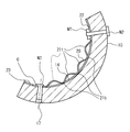
波板バネ20は、波状に湾曲した金属製の板バネである。波板バネ20は、保持枠30の外周面に当接した4つの頂部21t、保持枠10の内周面に当接した3つの谷部21b、を有している。詳細には、頂部21tは、保持枠30の曲面32cに当接し、谷部21bは、保持枠10の曲面12cに当接している。保持枠30の曲面32cと保持枠10の曲面12cとは、波板バネ20を介して対向している。頂部21tや谷部21bの数は上記に限定されない。波板バネ20は、光軸OP周りに略90°にわたって延びている。   The corrugated leaf spring 20 is a metal leaf spring curved in a wave shape. The corrugated spring 20 has four top portions 21 t that are in contact with the outer peripheral surface of the holding frame 30 and three valley portions 21 b that are in contact with the inner peripheral surface of the holding frame 10. Specifically, the top portion 21 t is in contact with the curved surface 32 c of the holding frame 30, and the valley portion 21 b is in contact with the curved surface 12 c of the holding frame 10. The curved surface 32 c of the holding frame 30 and the curved surface 12 c of the holding frame 10 are opposed to each other through the corrugated spring 20. The number of tops 21t and valleys 21b is not limited to the above. The corrugated spring 20 extends approximately 90 ° around the optical axis OP.

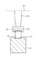
図3は、光軸OPを含む平面での保持枠10、30の断面図である。保持枠10、30には、それぞれ、波板バネ20を保持するための溝14、34が形成されている。溝14、34は、それぞれ、保持枠10の内周部、保持枠30の外周部に形成されている。溝14、34は、それぞれ、保持枠10、30の周方向に延びている。波板バネ20が、溝14、34内で保持されることにより、波板バネ20の位置が光軸OPの方向にずれることを防止している。   FIG. 3 is a cross-sectional view of the holding frames 10 and 30 in a plane including the optical axis OP. Grooves 14 and 34 for holding the corrugated spring 20 are formed in the holding frames 10 and 30, respectively. The grooves 14 and 34 are formed in the inner peripheral portion of the holding frame 10 and the outer peripheral portion of the holding frame 30, respectively. The grooves 14 and 34 extend in the circumferential direction of the holding frames 10 and 30, respectively. The corrugated spring 20 is held in the grooves 14 and 34 to prevent the corrugated spring 20 from being displaced in the direction of the optical axis OP.

次に、波板バネ20周辺の保持枠10の構造について詳細に説明する。図4は、波板バネ20周辺の構造を示した拡大図である。波板バネ20は、保持枠10に固定されている。波板バネ20の第1端部22は、ネジN2とナットNTとにより保持枠10に固定され、波板バネ20の第2端部23は、ネジN3とリング状のカラーCとにより保持枠10に固定されている。   Next, the structure of the holding frame 10 around the corrugated spring 20 will be described in detail. FIG. 4 is an enlarged view showing the structure around the corrugated spring 20. The corrugated spring 20 is fixed to the holding frame 10. The first end 22 of the corrugated spring 20 is fixed to the holding frame 10 by screws N2 and nuts NT, and the second end 23 of the corrugated spring 20 is secured by a screw N3 and ring-shaped collar C. 10 is fixed.

図5は、保持枠10と波板バネ20との分解斜視図である。波板バネ20の第1端部22、第2端部23は、波状ではなく、保持枠10の溝14に沿うように若干湾曲している。波板バネ20の第1端部22側には長孔24が形成され、第2端部23側には長孔25が形成されている。長孔24、25は、波板バネ20の長手方向に延びている。   FIG. 5 is an exploded perspective view of the holding frame 10 and the corrugated spring 20. The first end portion 22 and the second end portion 23 of the corrugated spring 20 are not corrugated, but are slightly curved along the groove 14 of the holding frame 10. A long hole 24 is formed on the first end 22 side of the corrugated spring 20, and a long hole 25 is formed on the second end 23 side. The long holes 24 and 25 extend in the longitudinal direction of the corrugated spring 20.

保持枠10には、ネジN2、N3にそれぞれ螺合するネジ孔16、17が形成されている。ネジ孔16、17は、溝14内を貫通している。ネジN2は保持枠10の外側からネジ孔16に螺合し、ネジN3は保持枠10の内側からネジ孔17に螺合している。   The holding frame 10 is formed with screw holes 16 and 17 that are screwed into the screws N2 and N3, respectively. The screw holes 16 and 17 penetrate the groove 14. The screw N2 is screwed into the screw hole 16 from the outside of the holding frame 10, and the screw N3 is screwed into the screw hole 17 from the inside of the holding frame 10.

次に、波板バネ20の保持枠10への固定方法について説明する。作業者は、長孔25とネジ孔17との位置を対応させて、カラーCを介してネジN3をネジ孔17に螺合させることにより、波板バネ20の第2端部23は保持枠10に固定する。この際、カラーCは長孔25の内縁に対して相対的にスライド可能である。従って、波板バネ20の第2端部23は長孔25の長さの分だけスライド可能に固定される。次に、作業者は、長孔24とネジ孔16との位置を対応させて、ネジN2をネジ孔16、ナットNTの孔Hに螺合させることにより、波板バネ20の第1端部22は保持枠10に仮固定させる。ここで仮固定とは、波板バネ20が保持枠10の内周面に向けて押圧された場合に、波板バネ20の第1端部22が溝14に沿ってスライド可能な程度の強さで固定されていることを意味する。従って、この状態においては、波板バネ20の第1端部22、第2端部23は、所定範囲だけ溝14に沿ってスライド可能である。   Next, a method for fixing the corrugated spring 20 to the holding frame 10 will be described. The operator associates the positions of the long hole 25 and the screw hole 17 and screws the screw N3 into the screw hole 17 via the collar C, whereby the second end 23 of the corrugated spring 20 is held by the holding frame. 10 is fixed. At this time, the collar C can slide relative to the inner edge of the long hole 25. Accordingly, the second end 23 of the corrugated spring 20 is fixed to be slidable by the length of the long hole 25. Next, the operator associates the positions of the long hole 24 and the screw hole 16 and screws the screw N2 into the screw hole 16 and the hole H of the nut NT, whereby the first end of the corrugated spring 20 is obtained. 22 is temporarily fixed to the holding frame 10. Here, temporary fixing means that the first end 22 of the corrugated spring 20 is slidable along the groove 14 when the corrugated spring 20 is pressed toward the inner peripheral surface of the holding frame 10. It means that it is fixed. Accordingly, in this state, the first end 22 and the second end 23 of the corrugated spring 20 can slide along the groove 14 by a predetermined range.

この状態で、作業者は、保持枠10内に保持枠30を配置する。次に、作業者は、調整ネジ11a、11bの螺合量を調整して、保持枠10に対する保持枠30の位置を調整する。この際、波板バネ20は保持枠10、30により圧縮されて長手方向に伸び、波板バネ20の第1端部22、第2端部23は溝14内をスライドする。保持枠30を所望の位置に調整し終わると、作業者はネジN2を強く締めて波板バネ20の第1端部22を保持枠10に固定する。これにより、波板バネ20の第1端部22の位置は保持枠10に固定される。このようにして、波板バネ20は保持枠10に固定される。波板バネ20が保持枠10に固定されることにより、保持枠30の位置の調整後に保持枠30の位置がずれることが抑制される。   In this state, the operator places the holding frame 30 in the holding frame 10. Next, the operator adjusts the screwing amount of the adjusting screws 11 a and 11 b to adjust the position of the holding frame 30 with respect to the holding frame 10. At this time, the corrugated spring 20 is compressed by the holding frames 10 and 30 and extends in the longitudinal direction, and the first end 22 and the second end 23 of the corrugated spring 20 slide in the groove 14. When the holding frame 30 has been adjusted to the desired position, the operator firmly tightens the screw N2 to fix the first end 22 of the corrugated spring 20 to the holding frame 10. As a result, the position of the first end 22 of the corrugated spring 20 is fixed to the holding frame 10. In this way, the corrugated spring 20 is fixed to the holding frame 10. By fixing the corrugated spring 20 to the holding frame 10, the position of the holding frame 30 is prevented from being shifted after the position of the holding frame 30 is adjusted.

尚、上述したように、波板バネ20の第2端部23は長孔25の長さの分だけスライド可能に固定される。このため、例えば、波板バネ20の第1端部22を保持枠10に固定した後に調整ネジ11a又は11bを保持枠30から離れるように移動させた場合には、波板バネ20の第2端部23は保持枠10に対してスライドして波板バネ20は長手方向に縮む。これにより保持枠30は、縮んだ波板バネ20により調整ネジ11a又は11b側に付勢される。   As described above, the second end portion 23 of the corrugated spring 20 is fixed to be slidable by the length of the long hole 25. For this reason, for example, when the adjustment screw 11 a or 11 b is moved away from the holding frame 30 after the first end 22 of the wave spring 20 is fixed to the holding frame 10, the second of the wave spring 20. The end 23 slides with respect to the holding frame 10 and the corrugated spring 20 contracts in the longitudinal direction. As a result, the holding frame 30 is urged toward the adjustment screw 11a or 11b by the contracted corrugated spring 20.

尚、波板バネ20の第1端部22、第2端部23の双方を固定した場合のバネ定数は、波板バネ20の第1端部22、第2端部23の双方を固定しない場合でのバネ定数に比べて30〜60倍に増加する。また、ネジN3とカラーCの代わりに、これらが一体に形成された段付きビスを用いてもよい。   The spring constant when both the first end 22 and the second end 23 of the corrugated spring 20 are fixed does not fix both the first end 22 and the second end 23 of the corrugated spring 20. It increases 30 to 60 times compared to the spring constant in some cases. Further, instead of the screw N3 and the collar C, a stepped screw in which these are integrally formed may be used.

図6A、6Bは、波板バネ20の変形の説明図である。図6Aは、自然の状態での波板バネ20を示しており、図6Bは、圧縮された状態での波板バネ20を示している。図6A、6Bでは、波板バネ20、保持枠10、30について展開して示している。波板バネ20は、外部から力が作用していない自然の状態では、全体として湾曲せずに一方向に伸びている。   6A and 6B are explanatory views of the deformation of the corrugated spring 20. FIG. 6A shows the corrugated spring 20 in a natural state, and FIG. 6B shows the corrugated spring 20 in a compressed state. 6A and 6B, the corrugated spring 20 and the holding frames 10 and 30 are shown expanded. The corrugated spring 20 extends in one direction without being bent as a whole in a natural state where no external force is applied.

複数の頂部21tと保持枠30とが当接し、複数の谷部21bと保持枠10とが当接して、波板バネ20が厚み方向に圧縮される。これにより、波板バネ20は長手方向に伸びる。よって、隣接する頂部21t間の距離、隣接する谷部21b間の距離も長くなる。   The plurality of top portions 21t and the holding frame 30 are in contact with each other, the plurality of valley portions 21b and the holding frame 10 are in contact with each other, and the corrugated spring 20 is compressed in the thickness direction. As a result, the corrugated spring 20 extends in the longitudinal direction. Therefore, the distance between the adjacent top portions 21t and the distance between the adjacent valley portions 21b are also increased.

このように、保持枠10、30が波板バネ20により押圧される点が複数箇所あるので、波板バネ20の付勢力が保持枠10、30に局所的に集中しない。これにより、保持枠10、30の変形や耐久性の低下などが防止できる。   As described above, since there are a plurality of points where the holding frames 10 and 30 are pressed by the corrugated spring 20, the urging force of the corrugated spring 20 does not concentrate locally on the holding frames 10 and 30. Thereby, a deformation | transformation of the holding frames 10 and 30 and a fall of durability can be prevented.

また、上述したように、波板バネ20が厚み方向に圧縮されることにより、隣接する頂部21t間の距離、隣接する谷部21b間の距離も長くなる。このため、波板バネ20により押圧される保持枠10の押圧点間の距離も長くなり、同様に、波板バネ20により押圧される保持枠30の押圧点間の距離も長くなる。このため、保持枠10、30に対して局所的に大きな負荷がかかるのを抑制できる。   Further, as described above, when the corrugated spring 20 is compressed in the thickness direction, the distance between the adjacent top portions 21t and the distance between the adjacent valley portions 21b are also increased. For this reason, the distance between the pressing points of the holding frame 10 pressed by the corrugated spring 20 also increases, and similarly, the distance between the pressing points of the holding frame 30 pressed by the corrugated spring 20 also increases. For this reason, it can suppress that a big load is locally applied with respect to the holding frames 10 and 30. FIG.

図7は、本実施例に対する比較例の説明図である。保持枠10xには、ピン18a、18bが固定されている。具体的には、ピン18a、18bは、保持枠10xに形成された2つの孔にそれぞれ固定されている。ピン18a、18bの先端には、それぞれコイル状のバネ19a、19bが連結されている。バネ19a、19bは、それぞれ保持枠30xの凹部34a、34bに当接している。バネ19a、19bは、保持枠30xを、それぞれ調整ネジ11a、11bに向けて付勢している。比較例においては、保持枠30xが付勢されている点は2点である。従って、例えばバネ19a、19bの付勢力が大きい場合には、保持枠30xに対して局所的に大きな負荷がかかり、保持枠30xが変形するおそれがある。このため、付勢力の小さいバネ19a、19bしか採用できないという制限があった。   FIG. 7 is an explanatory diagram of a comparative example with respect to the present embodiment. Pins 18a and 18b are fixed to the holding frame 10x. Specifically, the pins 18a and 18b are respectively fixed to two holes formed in the holding frame 10x. Coiled springs 19a and 19b are connected to the tips of the pins 18a and 18b, respectively. The springs 19a and 19b are in contact with the recesses 34a and 34b of the holding frame 30x, respectively. The springs 19a and 19b urge the holding frame 30x toward the adjusting screws 11a and 11b, respectively. In the comparative example, there are two points where the holding frame 30x is biased. Therefore, for example, when the urging force of the springs 19a and 19b is large, a large load is locally applied to the holding frame 30x, and the holding frame 30x may be deformed. For this reason, there is a limitation that only the springs 19a and 19b having a small urging force can be employed.

しかしながら、上述したように本実施例においては、保持枠30が付勢されている点は4点である。従って、保持枠10、30に対して局所的に大きな負荷がかかることを抑制している。また、これにより、波板バネ20全体が保持枠30に及ぼす付勢力の合計が比較的大きい場合であっても、波板バネ20は複数箇所で保持枠30に当接しているので、保持枠30に対して局所的に大きな負荷がかかることが抑制される。同様に、保持枠10に対しても、局所的に大きな負荷がかかることが抑制される。   However, as described above, in this embodiment, there are four points where the holding frame 30 is urged. Therefore, it is possible to prevent a large load from being locally applied to the holding frames 10 and 30. Further, as a result, even if the total urging force exerted on the holding frame 30 by the entire corrugated spring 20 is relatively large, the corrugated spring 20 is in contact with the holding frame 30 at a plurality of locations. It is suppressed that a large load is locally applied to 30. Similarly, it is possible to prevent the holding frame 10 from being subjected to a large load locally.

また、図7に示すように比較例では、保持枠30xの凹部34a、34bの底面は、平面である。この平面にバネ19a、19bが当接する。コイル状のバネ19a、19bを曲面に当接させると、保持枠30xに作用するバネ19a、19bの付勢力の方向が不安定となるおそれがあるからである。従って、保持枠30xでは、曲面状である保持枠30xの外周側にこのような平面を形成している。   As shown in FIG. 7, in the comparative example, the bottom surfaces of the recesses 34a and 34b of the holding frame 30x are flat. The springs 19a and 19b abut on this plane. This is because if the coiled springs 19a and 19b are brought into contact with the curved surface, the direction of the urging force of the springs 19a and 19b acting on the holding frame 30x may become unstable. Therefore, in the holding frame 30x, such a plane is formed on the outer peripheral side of the holding frame 30x having a curved shape.

しかしながら、本実施例においては、保持枠30の曲面32c、保持枠10の曲面12cに沿うように波板バネ20全体は湾曲可能である。このため、保持枠30に平面部分を形成しなくてもよい。   However, in the present embodiment, the entire corrugated spring 20 can be bent along the curved surface 32 c of the holding frame 30 and the curved surface 12 c of the holding frame 10. For this reason, it is not necessary to form a plane part in the holding frame 30.

比較例では、調整ネジ11aに向けて保持枠30xを付勢するバネ19aと、調整ネジ11bに向けて保持枠30xを付勢するバネ19bとが個別に設けられている。本実施例では、単体の波板バネ20により、保持枠30を調整ネジ11a、11bの双方に向けて付勢している。このため、本実施例ではバネの部品点数が削減されている。   In the comparative example, a spring 19a that biases the holding frame 30x toward the adjustment screw 11a and a spring 19b that biases the holding frame 30x toward the adjustment screw 11b are individually provided. In the present embodiment, the holding frame 30 is urged toward both the adjusting screws 11a and 11b by the single corrugated spring 20. For this reason, in this embodiment, the number of spring parts is reduced.

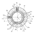
図8は、本実施例の変形例の説明図である。波板バネ20aは、6つの頂部21t、5つの谷部21b、を有している。また、波板バネ20aは、光軸OP周りに略120度にわたって延びている。保持枠30に当接する頂部21tの数が多いことにより、保持枠30に局所的に大きな負荷がかかることが抑制されている。   FIG. 8 is an explanatory diagram of a modification of the present embodiment. The corrugated spring 20a has six top portions 21t and five trough portions 21b. Further, the corrugated spring 20a extends approximately 120 degrees around the optical axis OP. Since the number of the top portions 21t that abut on the holding frame 30 is large, it is possible to prevent a large load from being applied locally to the holding frame 30.

図示はしていないが、例えば3つの頂部21t、2つの谷部21bを有した波板バネを用いてもよい。保持枠30に当接する波板バネの頂部21tは、少なくとも3つあればよい。また、波板バネの少なくとも一部が、光軸OP方向から見た場合に、軸線Aa、Abの間の領域であって光軸OPを介して調整ネジ11a、11bと対向する領域に配置されていればよい。   Although not shown, for example, a corrugated spring having three top portions 21t and two trough portions 21b may be used. There may be at least three top portions 21t of the corrugated springs that come into contact with the holding frame 30. Further, when at least a part of the corrugated spring is viewed from the direction of the optical axis OP, the corrugated spring is disposed in a region between the axes Aa and Ab and facing the adjustment screws 11a and 11b via the optical axis OP. It only has to be.

以上、本発明の実施例について詳述したが、本発明は係る特定の実施例に限定されるものではなく、特許請求の範囲に記載された本発明の要旨の範囲内において、種々の変形・変更が可能である。   Although the embodiments of the present invention have been described in detail above, the present invention is not limited to such specific embodiments, and various modifications and changes can be made within the scope of the gist of the present invention described in the claims. It can be changed.

上記実施例においては、波板バネ20の第1端部22、第2端部23の双方を保持枠10に固定したが、第1端部22、第2端部23の少なくとも一方を保持枠30に固定してもよい。また、波板バネ20の第1端部22、第2端部23の一方のみを、保持枠10又は保持枠30に固定してもよい。波板バネ20の第1端部22、第2端部23の双方とも固定しなくてもよい。波板バネは、光軸周りに90°未満の角度範囲にわたって延びていてもよい。   In the above embodiment, both the first end 22 and the second end 23 of the corrugated spring 20 are fixed to the holding frame 10, but at least one of the first end 22 and the second end 23 is held in the holding frame. You may fix to 30. Further, only one of the first end 22 and the second end 23 of the corrugated spring 20 may be fixed to the holding frame 10 or the holding frame 30. Both the first end 22 and the second end 23 of the corrugated spring 20 need not be fixed. The corrugated spring may extend over an angular range of less than 90 ° around the optical axis.

レンズ鏡筒を備えた撮像装置は、例えばスチルカメラ、ビデオカメラ、携帯電話、望遠鏡等である。   An imaging apparatus provided with a lens barrel is, for example, a still camera, a video camera, a mobile phone, a telescope, or the like.

調整される光学系は、最も被写体側に位置した光学系であってもよい。調整される光学系は、1枚のレンズであってもよいし、複数枚のレンズからなるレンズ群であってもよい。調整ネジは、3つ以上設けてもよい。   The optical system to be adjusted may be an optical system positioned closest to the subject. The optical system to be adjusted may be a single lens or a lens group including a plurality of lenses. Three or more adjustment screws may be provided.

1 レンズ鏡筒
10、30 保持枠
11a、11b 調整ネジ
12c、32c 曲面
20 波板バネ
21t 頂部
21b 谷部
22 第1端部
23 第2端部
24、25 長孔
121b レンズ
Aa、Ab 軸線
C カラー
N2、N3 ネジ
NT ナット
C カラー
OP 光軸
DESCRIPTION OF SYMBOLS 1 Lens barrel 10, 30 Holding frame 11a, 11b Adjustment screw 12c, 32c Curved surface 20 Wave plate spring 21t Top part 21b Valley part 22 1st end part 23 2nd end part 24, 25 Long hole 121b Lens Aa, Ab Axis C Color N2, N3 Screw NT Nut C Color OP Optical axis

Claims (6)

光学系を保持する第1保持枠と、
前記第1保持枠を保持する第2保持枠と、
前記第1保持枠と前記第2保持枠との間に配置された波板バネと、
前記第1保持枠を前記波板バネに向けて押すことにより前記第1保持枠を前記第2保持枠に対して位置決めする位置決め部と、を備えたレンズ鏡筒。
A first holding frame for holding the optical system;
A second holding frame for holding the first holding frame;
A corrugated spring disposed between the first holding frame and the second holding frame;
A lens barrel comprising: a positioning portion that positions the first holding frame with respect to the second holding frame by pushing the first holding frame toward the corrugated spring.
前記第1保持枠は、前記光学系の光軸方向から見た場合に略円形であり、
前記第2保持枠は、前記第1保持枠の外周側に配置され、
前記位置決め部は、前記第1保持枠へ進退可能に前記第2保持枠に支持された第1及び第2ネジである、請求項1のレンズ鏡筒。
The first holding frame is substantially circular when viewed from the optical axis direction of the optical system,
The second holding frame is disposed on an outer peripheral side of the first holding frame;
2. The lens barrel according to claim 1, wherein the positioning portion includes first and second screws supported by the second holding frame so as to be movable back and forth to the first holding frame.
前記光学系の光軸方向から見た場合に、前記波板バネの少なくとも一部分は、前記第1ネジの第1軸線と前記第2ネジの第2軸線との間の領域であって前記光学系の光軸を介して前記第1及び第2ネジと対向する領域に配置されている、請求項2のレンズ鏡筒。   When viewed from the optical axis direction of the optical system, at least a portion of the corrugated spring is a region between the first axis of the first screw and the second axis of the second screw, and the optical system. The lens barrel according to claim 2, wherein the lens barrel is disposed in a region facing the first and second screws via the optical axis. 前記波板バネの一端は、前記第1又は第2保持枠に固定されている、請求項1乃至3の何れかのレンズ鏡筒。   The lens barrel according to claim 1, wherein one end of the corrugated spring is fixed to the first or second holding frame. 前記第1保持枠は、第1曲面を有し、
前記第2保持枠は、前記第1曲面に対向する第2曲面を有し、
前記波板バネは、前記第1及び第2曲面に当接している、請求項1乃至4の何れかのレンズ鏡筒。
The first holding frame has a first curved surface,
The second holding frame has a second curved surface facing the first curved surface,
The lens barrel according to claim 1, wherein the corrugated spring is in contact with the first and second curved surfaces.
請求項1乃至5の何れかのレンズ鏡筒を備えた撮像装置。   An imaging device comprising the lens barrel according to claim 1.
JP2011058213A 2011-03-16 2011-03-16 Lens barrel and imaging apparatus Pending JP2012194370A (en)

Priority Applications (1)

Application Number Priority Date Filing Date Title
JP2011058213A JP2012194370A (en) 2011-03-16 2011-03-16 Lens barrel and imaging apparatus

Applications Claiming Priority (1)

Application Number Priority Date Filing Date Title
JP2011058213A JP2012194370A (en) 2011-03-16 2011-03-16 Lens barrel and imaging apparatus

Publications (2)

Publication Number Publication Date
JP2012194370A true JP2012194370A (en) 2012-10-11
JP2012194370A5 JP2012194370A5 (en) 2014-05-01

Family

ID=47086330

Family Applications (1)

Application Number Title Priority Date Filing Date
JP2011058213A Pending JP2012194370A (en) 2011-03-16 2011-03-16 Lens barrel and imaging apparatus

Country Status (1)

Country Link
JP (1) JP2012194370A (en)

Cited By (1)

* Cited by examiner, † Cited by third party
Publication number Priority date Publication date Assignee Title
WO2020261585A1 (en) * 2019-06-24 2020-12-30 株式会社レクザム Lens holding device and lens optical characteristic measuring device

Citations (4)

* Cited by examiner, † Cited by third party
Publication number Priority date Publication date Assignee Title
JPS60101869U (en) * 1983-12-19 1985-07-11 株式会社ニコン Solid-state image sensor positioning device
JP2001209118A (en) * 2000-01-26 2001-08-03 Hitachi Ltd Projection type display device
JP2002267911A (en) * 2001-03-13 2002-09-18 Olympus Optical Co Ltd Optical instrument
JP2010286681A (en) * 2009-06-12 2010-12-24 Nikon Corp Lens barrel and optical instrument

Patent Citations (4)

* Cited by examiner, † Cited by third party
Publication number Priority date Publication date Assignee Title
JPS60101869U (en) * 1983-12-19 1985-07-11 株式会社ニコン Solid-state image sensor positioning device
JP2001209118A (en) * 2000-01-26 2001-08-03 Hitachi Ltd Projection type display device
JP2002267911A (en) * 2001-03-13 2002-09-18 Olympus Optical Co Ltd Optical instrument
JP2010286681A (en) * 2009-06-12 2010-12-24 Nikon Corp Lens barrel and optical instrument

Cited By (1)

* Cited by examiner, † Cited by third party
Publication number Priority date Publication date Assignee Title
WO2020261585A1 (en) * 2019-06-24 2020-12-30 株式会社レクザム Lens holding device and lens optical characteristic measuring device

Similar Documents

Publication Publication Date Title
JP5779179B2 (en) Lens unit
US8270106B2 (en) Lens module
JP6192560B2 (en) Lens barrel and optical apparatus having the same
JP2012013981A (en) Zoom lens device
US10120161B2 (en) Lens barrel and optical apparatus having the same
US8917461B2 (en) Optical device and optical instrument
US11460692B2 (en) Spacer and camera module
JP2012141536A (en) Optical device and optical instrument
US7417805B2 (en) Camera device
JP5273063B2 (en) Optical apparatus and optical apparatus
US20110091199A1 (en) Camera module
JP2012194370A (en) Lens barrel and imaging apparatus
JP2011099966A (en) Optical element-holding device
JP2008180762A (en) Optical axis adjustment device
US8238048B2 (en) Camera module
US11269238B2 (en) Camera module
JP2007041141A (en) Lens retainer mechanism, lens position adjusting method, and camera module
JP2015158629A (en) Lens barrel, lens device having the same, and imaging device
US11506860B2 (en) Focusing device
JP2010169938A (en) Lens-barrel and optical equipment
JP2014153461A (en) Lens barrel, camera module and camera module manufacturing method
JP2013254050A (en) Lens barrel and optical device employing the same
JP2019133113A (en) Lens device
US20240134144A1 (en) Optical module
US20160223779A1 (en) Optical equipment

Legal Events

Date Code Title Description
A621 Written request for application examination

Free format text: JAPANESE INTERMEDIATE CODE: A621

Effective date: 20140304

A521 Written amendment

Free format text: JAPANESE INTERMEDIATE CODE: A523

Effective date: 20140314

A977 Report on retrieval

Free format text: JAPANESE INTERMEDIATE CODE: A971007

Effective date: 20141225

A131 Notification of reasons for refusal

Free format text: JAPANESE INTERMEDIATE CODE: A131

Effective date: 20150113

A02 Decision of refusal

Free format text: JAPANESE INTERMEDIATE CODE: A02

Effective date: 20150616