JP2012191889A - Seedling transplanter - Google Patents
Seedling transplanter Download PDFInfo
- Publication number
- JP2012191889A JP2012191889A JP2011058315A JP2011058315A JP2012191889A JP 2012191889 A JP2012191889 A JP 2012191889A JP 2011058315 A JP2011058315 A JP 2011058315A JP 2011058315 A JP2011058315 A JP 2011058315A JP 2012191889 A JP2012191889 A JP 2012191889A
- Authority
- JP
- Japan
- Prior art keywords
- turning
- planting
- clutch
- seedling
- lock mechanism
- Prior art date
- Legal status (The legal status is an assumption and is not a legal conclusion. Google has not performed a legal analysis and makes no representation as to the accuracy of the status listed.)
- Granted
Links
Images


Landscapes
- Guiding Agricultural Machines (AREA)
- Transplanting Machines (AREA)
- Lifting Devices For Agricultural Implements (AREA)
- Retarders (AREA)
Abstract
Description
本発明は、苗の植付設定を疎密調節可能に構成した苗移植機に関するものである。 The present invention relates to a seedling transplanting machine configured so that planting setting of seedlings can be adjusted.
先行技術文献1に記載の苗移植機には、旋回時に旋回内側のサイドクラッチを切って後輪への駆動力を停止させ、旋回開始位置と旋回終了位置の距離が近くなる構成がある。しかし、旋回動作を行なうと、旋回内側の後輪への駆動力が切れてしまうため、圃場の土質が柔らかい湿田等では、泥土が機体の前進を妨げてしまい、旋回に時間がかかって作業能率が低下したり、旋回終了位置が大幅にずれて苗の植付精度が低下する問題がある。
先行技術文献2では、制御機構を用いることによって、定期的に旋回内側の後輪に駆動力を供給する構成として、上記の問題を解消している。
The seedling transplanting machine described in Prior
In
しかしながら、旋回内側の伝動調節制御を実行するための構成が非常に複雑になるため、部品点数が増大し、コストの上昇やメンテナンス性の低下が問題となる。これに加えて、先行技術文件1のデフロック機構は、旋回時に前輪がスリップしたとき、作業者が操作しなければデフロック機構は作動しないため、突然のスリップ発生時により作業者が混乱して操作が遅れ、その結果、旋回終了位置がずれて苗の植付精度が低下したり、旋回作業にかかる時間が長くなり、作業能率が低下する問題がある。
さらに、先行文献1,2の自動リフト機構は、旋回時に植付部を最高位置まで上昇することから、その動力消費によって旋回に必要な出力が不足してしまう問題がある。
However, since the configuration for executing the transmission adjustment control inside the turning is very complicated, the number of parts is increased, which causes a problem of an increase in cost and a decrease in maintainability. In addition to this, the differential lock mechanism of Prior Art
Furthermore, since the automatic lift mechanism of the
本発明の目的は、簡易な構成の旋回内側の伝動調節によってコストの低減とやメンテナンス性の向上を図り、突然のスリップ発生にも対応を可能として植付精度と作業能率を確保でき、かつ、旋回に必要な出力の確保が可能となる苗移植機を提供することにある。 The purpose of the present invention is to reduce the cost and improve the maintenance by transmission adjustment inside the turning with a simple configuration, and can ensure planting accuracy and work efficiency as it can cope with sudden slip occurrence, and An object of the present invention is to provide a seedling transplanting machine that can ensure the output required for turning.
請求項1に係る発明は、圃場を走行する左右の前輪10,10と左右の後輪11,11を備えた走行車体2と、該左右の前輪10,10の動力を同調伝動するデフロック機構51aを備えたデフ装置51と、該左右の後輪11,11の動力をそれぞれ伝動解除する左右のクラッチ機構18c,18cと、機体旋回操作に応じて該旋回内側のクラッチ機構18c,18cのみに作用する左右の制御ロッド部材52,52と、機体旋回操作に応じて昇降リンク機構3により非作業位置に上昇可能に支持した植付装置4を備える苗移植機において、上記左右のクラッチ機構18c,18cの動作規制により左右の後輪動力を維持可能に設定するクラッチ設定機構53を設け、機体旋回時の前輪10,10のスリップによりデフロック機構51aを作動可能に上記デフ装置51を構成し、該デフロック機構51aの作動により植付装置4の上昇位置を低く抑える上昇規制機構Cを上記昇降リンク機構3に設けたことを特徴とする。
The invention according to
上記左右の制御ロッド部材を介して内側のクラッチ機構が後輪動力の伝動を解除し、クラッチ設定機構により内側クラッチが動作規制される場合は両後輪駆動が維持される。また、旋回時に前輪がスリップすると自動的にデフロック機構が作動して旋回内側と外側の前輪の回転が同調する。そして、旋回時の前輪スリップと連動して昇降リンク機構が上昇規制機構による所定高さで停止する構成としたため、植付装置の上昇に費やされる駆動出力が減少するため、旋回動作に十分な出力が供給される。 When the inner clutch mechanism releases the transmission of the rear wheel power through the left and right control rod members, and the inner clutch operation is restricted by the clutch setting mechanism, the driving of both rear wheels is maintained. Further, when the front wheel slips during turning, the differential lock mechanism is automatically activated to synchronize the rotation of the front wheels inside and outside the turning. Since the lifting link mechanism is stopped at a predetermined height by the ascent restriction mechanism in conjunction with the front wheel slip at the time of turning, the drive output spent for raising the planting device is reduced, so sufficient output for turning operation Is supplied.
請求項2に係る発明は、請求項1の構成において、前記左右の制御ロッド部材52,52には、それぞれの両端部間の相対動作を許容する伸縮部52cと、それぞれの伸縮部52cの相対動作を規制可能に緊張架設したガイド式のケーブル54を設け、該両ケーブル54,54と連結して弛緩操作可能に切替え保持するレバーによる切替操作部材55によって前記クラッチ設定機構53を構成したことを特徴とする。
上記切替操作部材をケーブルの緊張側に操作すると制御ロッド部材の両端間の相対動作が規制されるので、旋回操作に応じて旋回内側のクラッチ機構が伝動解除され、また、弛緩側に操作すると制御ロッド部材の両端間の相対動作が許容され、旋回操作によっても旋回内側の制御ロッド部材が作用しないことから、クラッチ機構が伝動を継続して旋回内側の後輪が回転駆動される。
According to a second aspect of the present invention, in the configuration of the first aspect, the left and right
When the switching operation member is operated to the cable tension side, the relative movement between both ends of the control rod member is restricted, so that the clutch mechanism on the inner side of the turning is released according to the turning operation, and when the operation is performed to the relaxation side, the control is performed. Since the relative movement between both ends of the rod member is allowed and the control rod member inside the turning does not act even by the turning operation, the clutch mechanism continues to transmit and the rear wheel inside the turning is driven to rotate.
請求項3の発明は、請求項1または2の構成において、切替操作部材55に設けた突起状の接触体の位置検出により操作位置を検出する切替検知部材58を設け、左右のクラッチ機構18c,18cの動作を規制する操作位置Bの場合に作業者に報知する報知部材59を設けたことを特徴とする。
上記切替操作部材の操作によって、切替検知部材が検知状態となると報知部材が作動する。
According to a third aspect of the present invention, in the configuration of the first or second aspect, the
When the switching detection member is in a detection state by the operation of the switching operation member, the notification member is activated.
請求項4の発明は、請求項1から3のいずれか1項の構成において、前記左右の後輪11,11は、それぞれの駆動力に応じて後輪ギヤケース18,18が立ち上がることによって支持高さ位置を移動可能にスイング支持した上で所定の高位置に達したことを検知するスイング検知部材18s,18sを設け、旋回開始から所定時間の範囲について旋回外側の移動検知部材18sが所定の高位置を検知しない場合に前記デフロック機構51aを作動させることを特徴とする。
旋回時に旋回外側の後輪の滑りによって支持高さが所定高さに達しなかった場合にデフロック機構が作動する構成としたことにより、作業者がデフロック機構の操作を忘れても自動的にデフロック機構が作動する。
According to a fourth aspect of the present invention, in the configuration according to any one of the first to third aspects, the left and right
The diff lock mechanism is activated when the support height does not reach the specified height due to slippage of the rear wheel outside the turn during turning, so that even if an operator forgets to operate the diff lock mechanism, the diff lock mechanism is automatically activated. Operates.
請求項5の発明は、請求項1から4のいずれか1項の構成において、前記昇降リンク機構3の昇降高さを検出する昇降高さ検知部材3hと、デフロック機構51aの作動を検知するデフロック検知部材51sとを設け、デフロック機構51aの作動時に昇降リンク機構3を非作業高さより低い所定高さで上昇停止させることを特徴とする。
上記デフロック機構を作動させると昇降リンク機構により植付装置を所定高さで停止する構成としたため、植付装置が圃場面に接触することなく旋回することができ、この時、植付装置の昇降に費やされる駆動出力が減少するため、旋回動作に十分な出力が供給される。
According to a fifth aspect of the present invention, in the configuration of any one of the first to fourth aspects, a lift
When the differential lock mechanism is operated, the planting device is stopped at a predetermined height by the lifting link mechanism, so that the planting device can turn without contacting the field scene. Since the drive output consumed for the rotation is reduced, an output sufficient for the turning operation is supplied.
請求項6の発明は、請求項5の構成において、前記植付装置4に苗の有無を検出する苗検出部材を設け、苗が無い状態では前記昇降高さ検知部材3hによる植付高さの検知を停止することを特徴とする。
植付装置に苗が無くなると、旋回時の昇降リンク機構の上昇規制を解除する構成としたことにより、植付装置の重量が軽くなって動力負荷が少ない状況下で圃場面から十分に上昇させて旋回ができる。
According to a sixth aspect of the present invention, in the configuration of the fifth aspect, the planting device 4 is provided with a seedling detection member for detecting the presence or absence of a seedling. The detection is stopped.
When the planting device runs out of seedlings, the lifting restriction of the lifting link mechanism during turning is canceled, so that the planting device can be lifted sufficiently from the field scene under the condition that the weight of the planting device is light and the power load is low. Can turn.
請求項1に係る発明によると、旋回時は、左右の制御ロッド部材を介して内側のクラッチ機構が後輪動力の伝動を解除し、クラッチ設定機構により内側クラッチが動作規制される場合は両後輪駆動が維持されるので、圃場の土質が柔らかく後輪の回転が妨げられるとき等に適用すれば、旋回中に機体が停止することが防止され、作業能率が向上する。
また、旋回時に前輪がスリップすると自動的にデフロック機構が作動して旋回内側と外側の前輪の回転が同調するので、圃場の土質が柔らかく前輪の推進が妨げられることがあっても、前輪が空回りして動かなくなることが防止され、作業能率が向上する。
そして、旋回時の前輪スリップと連動して昇降リンク機構3が上昇規制機構による所定高さで停止する構成としたため、植付装置の上昇に費やされる駆動出力が減少するため、旋回動作に十分な出力が供給され、圃場端で機体の走行が妨げられることが無く、作業能率が向上する。
According to the first aspect of the present invention, when turning, the inner clutch mechanism releases the transmission of the rear wheel power via the left and right control rod members, and the rear clutch power is controlled when the inner clutch operation is restricted by the clutch setting mechanism. Since the wheel drive is maintained, if applied to the field where the soil quality is soft and the rotation of the rear wheels is hindered, the airframe is prevented from stopping during the turn and the work efficiency is improved.
Also, if the front wheel slips during turning, the differential lock mechanism automatically operates and the rotation of the front wheels on the inside and outside of the turning synchronizes, so even if the soil is soft and the propulsion of the front wheels may be hindered, the front wheels will run idle. This prevents it from moving and improves work efficiency.
And since it was set as the structure where the raising / lowering
請求項2に係る発明によると、請求項1の発明の効果に加え、切替操作部材をケーブルの緊張側に操作すると制御ロッド部材の両端間の相対動作が規制され、旋回操作に応じて旋回内側のクラッチ機構が伝動解除され、また、弛緩側に操作すると制御ロッド部材の両端間の相対動作が許容され、旋回操作によっても旋回内側の制御ロッド部材が作用しないことから、クラッチ機構が伝動を継続して旋回内側の後輪が回転駆動される。
このように、切替操作部材によってクラッチ機構の動作切替えが可能となり、クラッチ機構が動作して旋回内側の後輪が無動力の場合は旋回内側と外側の後輪回転数の差が大きくなって旋回開始位置と旋回終了位置の距離を短くできるので、苗の植付列が離れにくくなって植付精度が向上し、また、伝動継続の場合は旋回内側の後輪が駆動回転するため、柔らかい土質の圃場でも両後輪の回転を維持できるので、湿田の旋回中に走行が停止することが防止され、作業能率が向上する。
According to the invention according to
As described above, the switching operation member can switch the operation of the clutch mechanism, and when the clutch mechanism is operated and the rear wheels on the inside of the turn are non-powered, the difference between the number of rotations of the rear wheels on the inside and outside of the turning becomes large. Since the distance between the starting position and the turning end position can be shortened, the planting row of the seedlings is less likely to be separated, and the planting accuracy is improved. Since the rotation of both rear wheels can be maintained even in this field, it is possible to prevent the traveling from stopping while the wet field is turning and to improve the work efficiency.
請求項3に係る発明によると、請求項1または2の発明の効果に加え、上記切替操作部材の操作によって切替検知部材が検知状態となると報知部材が作動することにより、圃場の土質が柔らかいことを作業者に気付かせることができるので、作業者は土質の柔らかい圃場に対応する操作を行い、苗の植付走行姿勢を安定させられるため、植付精度や作業能率が向上する。
According to the invention of
請求項4に係る発明によると、請求項1から3のいずれか1項の効果に加え、旋回時に旋回外側の後輪の滑りによって支持高さが所定高さに達しなかった場合、デフロック機構が作動する構成としたことにより、作業者がデフロック機構の操作を忘れても自動的にデフロック機構が作動して柔らかい圃場端で旋回しやすくなるので、圃場端で停止している時間が短くなり、作業能率が向上する。
According to the invention of claim 4, in addition to the effect of any one of
請求項5に係る発明によると、請求項1から4のいずれか1項の効果に加え、デフロック機構を作動させると昇降リンク機構により植付装置を所定高さで停止する構成としたため、植付装置が圃場面に接触することなく旋回することができ、この時、植付装置の昇降に費やされる駆動出力が減少するため、旋回動作に十分な出力が供給され、圃場端で機体の走行が妨げられることが無く、作業能率が向上する。
According to the invention according to claim 5, in addition to the effect of any one of
請求項6に係る発明によると、請求項5の効果に加え、植付装置に苗が無くなると、旋回時の昇降リンク機構の上昇規制を解除する構成としたことにより、植付装置の重量が軽くなって動力負荷が少ない状況下で圃場面から十分に上昇させて旋回することができるので、旋回時に植付装置の下部が圃場面に接触することが防止される。 According to the invention of claim 6, in addition to the effect of claim 5, when there is no seedling in the planting device, the lifting restriction of the lifting link mechanism at the time of turning is canceled, so that the weight of the planting device is increased. Since it can lighten and turn up sufficiently from a field scene under the condition that there is little power load, it is prevented that the lower part of a planting device contacts a field scene at the time of turning.
以下に、本発明の実施の形態にかかる苗移植機について説明する。
図1及び図2は本実施の形態にかかる苗移植機の側面図と平面図である。この苗移植機1は、圃場を走行する左右の前輪10,10と左右の後輪11,11を備えた走行車体2の後部に施肥装置5、昇降リンク機構3等を備え、この昇降リンク機構3介して植付装置4が昇降可能に構成される。
Below, the seedling transplanting machine concerning embodiment of this invention is demonstrated.
FIG.1 and FIG.2 is the side view and top view of a seedling transplanter concerning this Embodiment. This
詳細には、走行車体2は、駆動輪である左右一対の前輪10,10及び左右一対の後輪11,11を備えた四輪駆動車両であって、機体の前部にミッションケース12が配置され、その左右側方に操向可能に前輪ファイナルケース13,13が設けられ、該左右前輪ファイナルケース13,13に左右前輪10,10が各々取り付けられている。
Specifically, the
また、ミッションケース12の背面部にメインフレーム15の前端部が固着されており、他方、そのメインフレーム15の後端部に設けた左右後輪ギヤケース18,18が支持され、軸支した後輪車軸17,17に後輪11,11が取り付けられている。
Further, the front end portion of the
エンジン20はメインフレーム15の上に搭載されており、該エンジン20の回転動力が、ベルト伝動装置21及びHST23を介してミッションケース12に伝達される。ミッションケース12に伝達された回転動力は、該ケース12内のトランスミッションにより変速された後、走行動力と外部取出動力に分離して取り出される。そして、走行動力は、一部が前輪ファイナルケース13,13に伝達されて前輪10,10を駆動すると共に、残りが左右後輪ギヤケース18,18に伝達されて左右後輪11,11を駆動する。
The
また、ミッションケース12の右側側面より取出された外部取出動力は、植付伝動軸26によって植付装置4へ伝動される。尚、施肥装置5の肥料繰出し機構へは、右後輪ギヤケース18から動力が駆動軸にて取出されて伝動される。
Further, the external extraction power extracted from the right side surface of the
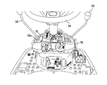
エンジン20の上部はエンジンカバー30で覆われており、その上に座席31が設置されている。座席31の前方には各種操作機構を内蔵するフロントカバー32があり、その上方に前輪10,10を操向操作する操舵部材34が設けられている。なお35はハンドシャフトである。このフロントカバー32内には、リザーバタンク16を設け、前記HST23とパイプ19で連結して高い位置からオイルをHST23に供給するようにしている。
The upper part of the
なお、操舵部材34の右側には、植付装置4の昇降を設定するための植え付け昇降レバー33が設けられている。
また、操舵部材34の左側には、走行車体2の前進、後進、速度などを設定する変速レバー36が設けられている。
A
On the left side of the steering
エンジンカバー30及びフロントカバー32の下端左右両側は水平状のフロアステップ37になっている。
フロアステップ37の左右前部には複数の貫通孔が形成されており、座席31に着座して機体を操縦する操縦者が左右前輪10,10を見通せることができて操縦が容易な構成となっていると共に、該ステップ37を歩く作業者の靴についた泥が圃場に落下するようになっている。
The
A plurality of through holes are formed in the left and right front portions of the floor step 37, so that a driver who is seated on the
昇降リンク装置3は平行リンク構成であって、1本の上リンク40と左右一対の下リンク41,41を備えている。これらリンク40,41,41は、その基部側がメインフレーム15の後端部に立設した背面視門形のリンクベースフレーム42に回動自在に取り付けられ、先端側には縦リンク43が連結されている。そして、縦リンク43の下端部に、植付装置4に回転自在に支承された連結軸44が挿入連結され、連結軸44を中心として植付装置4がローリング自在に連結されている。
The elevating
メインフレーム15に基部を回動自在に枢支した昇降油圧シリンダ46の先端を上リンク40に一体形成したスイングアーム(図示せず)の先端部に連結して設けており、該昇降油圧シリンダ46を油圧で伸縮させることにより、上リンク40が上下に回動し、植付装置4がほぼ一定姿勢のまま昇降する。また、作業者が機体に乗り降りする時に足を載せるステップとして左右補助ステップ28,28を備えている。
A lifting hydraulic cylinder 46 whose base is pivotally supported on the
(旋回連動制御)
圃場における旋回走行については、オートリフト機能によって操舵部材であるハンドル34の回動操作による機体旋回と連動して植付装置4を非作業高さ位置まで昇降制御するほか、圃場の走行状況に応じて、その昇降高さを変更し、また、左右の前輪10,10、左右の後輪11,11の走行動力を制御するべく構成する。
(Swivel interlocking control)
For turning traveling in the field, the planting device 4 is controlled to move up and down to a non-working height position in conjunction with the turning of the
詳細には、前輪10,10の走行動力は、ミッションケース12に一体に構成されたデフロック機構51a付きのデフ装置51を介して左右側方の前輪ファイナルケース13,13を介して伝動され、機体旋回時の前輪10,10のスリップによりデフロック機構51aを作動させて両輪同速駆動可能に構成する。
Specifically, the traveling power of the
左右の後輪ギヤケース18,18は、メインフレーム15の後端部に設けた左右のスイング支軸18b,18bを支点にして各後輪11の駆動力に応じて個別に機体を上昇するようにスイング支持する。このスイング支持は、後輪ギヤケース18が後輪11の駆動力に応じて作用する反力モーメントを受けてそれぞれ所定の角度範囲で立ち上がるように構成する。また、左右の後輪ギヤケース18,18に左右後輪伝動軸18a,18aからミッションケース12による変速動力を受けるとともに、それぞれクラッチ機構18c,18cを内設し、各クラッチ機構18c,18cの動作制御により左右の後輪11,11に対する動力伝達を停止可能に構成する。
The left and right rear
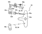
左右のクラッチ機構18c,18cの操作は、図3の部分側面図を伴う要部拡大図に示すように、操舵部材であるハンドル34の回動に対して逆方向に回動する逆動リンク34aを介して、操舵操作と連動して旋回内側のみに作用する左右の制御ロッド部材52,52を設けて個々に制御可能に構成する。これら各制御ロッド部材52には、各クラッチ機構18cを動作させる入力アーム18eに対する作用範囲を限定するための所定長さの遊動長孔52hを形成することにより、ハンドル34の回動操作による旋回内側の所定の舵角範囲に限定してクラッチ機構18cを動作可能に構成する。
The operation of the left and right
また、左右のクラッチ機構18c,18cについて、ハンドル34の回動操作によっても左右後輪11,11を駆動するように設定するクラッチ設定機構53をガイドケーブル54によって構成する。詳細には、左右の制御ロッド部材52,52について、それぞれ両端部52a,52b間の相対動作を許容する伸縮部52cを介設する。この伸縮部52cを挟んでアウタガイド54gの支持位置が移動可能にガイドケーブル54を架設し、このガイドケーブル54の緊張によって伸縮部52cを拘束可能に構成する。
In addition, a
これら両ケーブル54,54の終端側には、図4の部分平面図を伴う要部拡大側面図に示すように、緊張と弛緩を切替え可能に保持するレバーによる切替操作部材55を設ける。この切替操作部材55は、畦クラッチレバーの支軸56に軸支してそのボス部55bに一体に設けた2つのアーム55a,55aにそれぞれケーブル54,54と切替操作部材55を連結し、その緊張と弛緩とに対応する切替操作部材55の角度位置A,Bを「標準」及び「湿田」の位置として切替え可能に保持するガイド溝57a,57bを形成したレバーガイド57を設ける。その弛緩位置Bにはリミットスイッチ等によるレバー位置検知部材58を設けてクラッチ設定機構53の設定状態を報知可能に構成する。
As shown in the enlarged side view of the main part with a partial plan view of FIG. 4, a switching
植付装置4は、機体旋回の際のハンドル操作に応じて昇降リンク機構3により非作業高さ位置まで上昇可能に制御するとともに、図5の昇降制御のシステムブロック図に示すように、昇降位置センサ3hとデフロック機構51aの作動信号を制御入力として昇降バルブ3vを制御可能に構成する。湿田等の旋回の際に前輪10,10がスリップした場合は、図6のフローチャートに示すように、デフロック51aを作動する第1の処理ステップ(以下において「S1」のごとく略記する。)に続き、植付装置4の上昇開始の判定(S2)により、別途定めた上昇限度(例えば、40cm)まで昇降バルブ3vを駆動制御(S3,S4)する制御部Cの制御処理により上昇規制機構を構成する。この上昇規制機構は所定高さ位置に設けたリミットスイッチによって構成してもよい。
The planting device 4 is controlled so that it can be raised to the non-working height position by the
上記構成の苗移植機1は、クラッチ設定機構53の切替操作部材55をレバーガイド57の「標準」位置である緊張位置Aに保持した場合に、ケーブル54の緊張によって左右の制御ロッド部材52,52の伸縮部52cが拘束されることから、ハンドル34の回動操作による機体旋回時は、旋回内側のクラッチ機構18cが作動して対応する後輪11の動力伝動が停止され、一方、切替操作部材55を「湿田」位置である弛緩位置Bに操作した場合に、ケーブル54の弛緩によって左右の制御ロッド部材52,52の伸縮部52cの拘束が解除されるので、ハンドル34の回動操作によっても旋回内側のクラッチ機構18cが作動することなく両後輪11,11による推進力が維持される。
When the switching
また、旋回中に前輪10,10がスリップした場合は、デフ装置51のデフロック機構51aが作動して両前輪10,10が同速駆動されて推進力が維持され、このデフロック機構51aの作動と連動して、植付装置4の上昇位置が非作業高さより低い位置に抑えられることから、その上昇駆動の出力損失が抑えられて走行系の動力供給の低下を招くことなく走行推進力が確保され、泥地や湿田であっても走行が安定する。
Further, when the
したがって、切替操作部材55を緊張位置Aに設定した場合の旋回外側の片後輪11のみの駆動により、標準的な圃場における小半径の旋回走行を確保することができ、また、弛緩位置Bに設定した場合の両後輪11,11の駆動により、走行抵抗の大きい湿田における走行性を確保することができることから、簡易に切替え操作が可能な切替操作部材55を備える簡易な構成のクラッチ設定機構53により、標準的な圃場の旋回性を確保した上で、湿田旋回時の走行性を確保することができ、合わせて旋回圃場の状況に応じた両前輪10,10の推進力調整とエンジン動力の配分調整とにより、湿田旋回時の走行性を向上することができる。
Therefore, by driving only the rear
このように、クラッチ機構18cが動作して旋回内側の後輪11が無動力となる場合は、旋回内側と外側の後輪11,11の回転数の差が大きくなって旋回開始位置と旋回終了位置の距離を短くできるので、隣接する苗の植付列同士が離れにくくなるため、苗の植付精度が向上する。
As described above, when the
一方、湿田旋回時の走行性向上により、圃場の土質が柔らかく、旋回内側の後輪11の回転が妨げられるとき等に適用すれば、旋回中に機体が停止することが防止され、作業能率が向上する。
また、旋回時に前輪10,10がスリップすると自動的にデフロック機構51aが作動して旋回内側と外側の前輪10,10の回転が同調するので、圃場の土質が柔らかく前輪の推進が妨げられることがあっても、前輪10,10が空回りして動かなくなることが防止され、旋回中に走行が停滞、或いは停止することが無く、作業能率が向上する。
On the other hand, if applied when the soil quality of the field is soft and the rotation of the
Further, when the
そして、旋回時の前輪スリップと連動して昇降リンク機構3が上昇規制機構Cによる所定高さで停止する構成としたため、植付装置4の上昇に費やされる駆動出力が減少するため、旋回動作に十分な出力が供給され、圃場端で機体の走行が妨げられることが無く、作業能率が向上する。
In addition, since the elevating
切替操作部材55による後輪クラッチ機構の設定切替えの際は、切替操作部材55の操作によって切替検知部材58が検知状態となるとブザーやランプなどによる報知部材59が作動することにより、圃場の土質が柔らかいことを作業者に気付かせることができるので、作業者は土質の柔らかい圃場に対応する操作を行い、苗の植付走行姿勢を安定させられるため、植付精度や作業能率が向上する。
When the setting of the rear wheel clutch mechanism is switched by the switching
旋回時における植付装置4の上昇動作は、デフロック機構51aの作動と対応して植付装置を所定高さで停止する構成としたため、植付装置4が圃場面に接触することなく旋回することができ、この時、植付装置4の昇降に費やされる駆動出力が減少するため、旋回動作に十分な出力が供給され、圃場端で機体の走行が妨げられることが無く、作業能率が向上する。
The ascending operation of the planting device 4 at the time of turning is configured to stop the planting device at a predetermined height corresponding to the operation of the
(後輪スリップ検出)
次に、後輪スリップの検出による走行伝動制御について説明する。
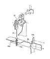
スイング支持した後輪ギヤケース18は、図7の要部拡大側面図に示すように、後輪11の駆動力Fが大きい場合にその反力モーメントによって後輪ギヤケース18がスイング動作して機体を上昇支持し、一方、後輪11がスリップした場合は、駆動力が抑えられて後輪ギヤケース18がスイング動作しないことから、この後輪ギヤケース18のスイング動作を検出するスイングセンサ18sを左右のスイング支軸18b,18bの近傍に設ける。
(Rear wheel slip detection)
Next, travel transmission control based on detection of rear wheel slip will be described.
As shown in the enlarged side view of the main part of FIG. 7, the rear
機体の旋回開始から旋回終了までの間において、旋回外側のスイングセンサ18sによる検出が無い場合には、デフロック機構51aを作動するように制御することにより、後輪11がスリップする圃場状況に対応して両前輪10,10による推進力を確保することができるので、湿田旋回時の走行性を向上することができる。
If there is no detection by the
(オートリターンケーブル)
次に、植付装置4の上昇限度を設定するオートリターンケーブルについて説明する。
植付装置4のオートリターンケーブル61は、図8の要部斜視図に示すように、ボンネット内に配置された油圧昇降バルブの制御入力カム62と連結するガイドケーブルであり、植付装置4が昇降リンク機構3の上昇動作によって緊張することにより制御入力カム62に作用し、同昇降リンク機構3の上昇動作を停止させてその上限位置を規定する。この上限位置である緊張位置を上下に切替えるために、アウタガイド61gをレバー部材63と連結し、このレバー部材63の一端を支点63pに軸支し、レバーガイド63hによって高低の2ポジションA,Bに保持可能に構成する。
(Auto return cable)
Next, the auto return cable for setting the ascent limit of the planting device 4 will be described.
The
上記構成のオートリターンケーブル61により、レバー部材63の保持位置に応じて変化するガイドケーブル61の緊張位置によって植付装置4の自動上昇の上限位置が切替えられることから、レバー部材63の高保持位置Aを「標準」の旋回による非作業高さとし、低保持位置Bを「湿田」の旋回による所定の低位置(例えば40cm)として機体旋回の際の植付装置4の自動上昇の上限位置の切替え設定が可能となるので、「湿田」の選択により、旋回時の出力損失を防止することができる。
Since the
(苗減少検知制御)
次に、植付装置4の苗減少時の制御について説明する。
植付装置4に苗の有無を検出する苗検出部材4sを設け、旋回時に苗が無い状態では前記昇降位置検知部材3hによる昇降高さの検知を停止することにより、昇降高さ規制によることなく、通常の非作業高さ位置まで植付装置4を上昇させるように構成する。
(Seedling reduction detection control)
Next, the control at the time of seedling reduction of the planting apparatus 4 will be described.
The planting device 4 is provided with a seedling detection member 4s for detecting the presence or absence of seedlings, and in the state where there is no seedlings at the time of turning, the detection of the elevation height by the elevation
このように、植付装置4に苗が無くなると、旋回時の昇降リンク機構3の上昇規制を解除する構成としたことにより、植付装置4の重量が軽くなって動力負荷が少ない状況下で圃場面から十分に上昇させて旋回することができるので、湿田旋回時に植付装置4の下部が圃場面に接触することが防止される。
Thus, when there is no seedling in the planting device 4, under the situation where the weight of the planting device 4 is light and the power load is small by the configuration in which the lifting restriction of the
(昇降レバー)
Zターンと略称する旋回連動制御において、旋回終了による植付装置4の確実な植付け再開のために、図9の昇降レバー33の支持構成の側面図に示すように、支点33hによって前後に傾動操作可能な昇降レバー33を動作させるモータ71のアーム72を長孔リンク73で連結し、植付上げ位置にある昇降レバー33の手動操作を可能としつつ、植付下げの位置に昇降レバー33を移動させることにより、植付装置4の昇降レバー33の「下げ」の位置から「植付入」の位置までの間について、モータ71を戻さないように構成する。
(Elevating lever)
In the turn interlocking control abbreviated as Z-turn, in order to reliably replant the planting device 4 at the end of the turn, as shown in the side view of the support structure of the
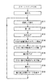
詳細には、昇降レバーの制御は、図10のフローチャートに示すように、このZターン旋回連動制御の適用によりモータ71が植付上げの状態で植付が開始され、直進走行(S11)に続くハンドル操作(S12)により、植付装置4上昇の油圧制御(S13)とともに左右の後輪11,11の回転カウントを開始(S14)し、回転の少ない方が0.4回転(S15)の時に植付上げから植付下げにモータ71を駆動(S16)し、次いで、後輪回転の少ない方が0.95回転(S17)の時に植付入のモータ駆動(S18)してモータ71を植付上位置(S19)に戻すように制御処理を構成する。
Specifically, as shown in the flowchart of FIG. 10, the control of the lift lever starts planting in a state where the
上記制御により、植付下げ(S16)から植付入(S18)の間にモータが上に戻らないことから、旋回終了の際の植付け下げから植付け開始までの間に、ハンドル操作が遅れてオートリフトが開始されても、植付装置4の上昇を抑えて植付を開始することができる。したがって、従来の如く、旋回終了時の植付け再開のために、植付装置4の「下げ」の位置から植付「入」の位置までの間に1度モータを戻すようにしていたことに伴い、ハンドル34の戻し操作が遅れるとオートリフト機能によって植付装置4が再び上昇するという問題を解消することができる。
By the above control, the motor does not return upward during planting (S16) to planting (S18), so the steering wheel operation is delayed from the planting to the start of planting at the end of turning. Even if the lift is started, the planting device 4 can be prevented from rising and planting can be started. Therefore, as in the past, in order to resume planting at the end of turning, the motor is returned once between the “down” position of the planting device 4 and the planting “on” position. If the return operation of the
また、上記構成において、自動植付けの解除による図11のフローチャートに示すように、植付装置4の「下げ」の位置から植付「入」の位置までの間に、植え始め位置を調整するための植付位置ダイヤルの解除(S21)によってモータが戻る(S22)ようにすることにより、万が一、手動による油圧上げの昇降レバー33の操作が必要な場合の対応が可能となる。
Further, in the above configuration, in order to adjust the planting start position between the “down” position of the planting device 4 and the planting “on” position as shown in the flowchart of FIG. By releasing the planting position dial (S21), the motor is returned (S22), so that it is possible to cope with the case where the manual operation of the lifting
さらに、植付位置ダイヤル75は、図12のダイヤルガイドの拡大見取図に示すように、植付位置75aの設定に加え、植付下げから植付入までの間でもモータ71を戻すかを戻さないかを選択できるように解除位置75bを設け、この解除位置75bにレバーの固定とフリーの位置を選択可能に構成することにより、植付位置ダイヤル75の事前のダイヤル設定によって切替えが可能となる。
Further, as shown in the enlarged sketch of the dial guide in FIG. 12, the
また、図13の操作パネルの見取図に示すように、解除位置75bの切替えのために、固定とフリーを切替える切替スイッチ76を別途設けることによっても、上記同様に、解除位置75bのダイヤル操作による事前設定が可能となる。
In addition, as shown in the sketch of the operation panel in FIG. 13, a
1 苗移植機
2 走行車体
3 昇降リンク機構
3h 昇降位置検知部材(昇降位置センサ)
4 植付装置
4s 苗検出部材
10 前輪
11 後輪
18 後輪ギヤケース
18b スイング支軸
18e 入力アーム
18s スイングセンサ
33 昇降レバー
34 ハンドル(操舵部材)
34a 逆動リンク
46 昇降油圧シリンダ
51 デフ装置
51a デフロック機構
52 制御ロッド部材
52c 伸縮部
52h 遊動長孔
53 クラッチ設定機構
54 ガイドケーブル
55 切替操作部材
57 レバーガイド
58 レバー位置検知部材
59 報知部材
A 緊張位置(高保持位置)
B 弛緩位置(低保持位置)
C 上昇規制機構
F 駆動力
DESCRIPTION OF
4 planting device 4s seedling
34a Reverse link 46 Elevating hydraulic cylinder 51
B Relaxing position (low holding position)
C Ascent control mechanism F Driving force
Claims (6)
上記左右のクラッチ機構(18c,18c)の動作規制により左右の後輪動力を維持可能に設定するクラッチ設定機構(53)を設け、機体旋回時の前輪(10,10)のスリップによりデフロック機構(51a)を作動可能に上記デフ装置(51)を構成し、該デフロック機構(51a)の作動により植付装置(4)の上昇位置を低く抑える上昇規制機構(C)を上記昇降リンク機構(3)に設けたことを特徴とする苗移植機。 A traveling vehicle body (2) provided with left and right front wheels (10, 10) and left and right rear wheels (11, 11) traveling on a farm field, and a differential lock mechanism (tuned) for transmitting power of the left and right front wheels (10, 10) synchronously. 51a), a left and right clutch mechanism (18c, 18c) for releasing transmission of the power of the left and right rear wheels (11, 11), and the inside of the turn according to the turning operation of the body Left and right control rod members (52, 52) acting only on the clutch mechanism (18c, 18c), and a planting device (4) supported so as to be lifted to a non-working position by the lift link mechanism (3) in accordance with the turning operation of the machine body )
A clutch setting mechanism (53) is provided for setting the left and right rear wheel power so that the left and right rear wheel power can be maintained by restricting the operation of the left and right clutch mechanisms (18c, 18c), and the differential lock mechanism ( The differential device (51) is configured to be operable 51a), and the lift restricting mechanism (C) that keeps the rising position of the planting device (4) low by the operation of the differential lock mechanism (51a) is provided with the lift link mechanism (3 A seedling transplanting machine characterized in that it is provided in).
Priority Applications (1)
| Application Number | Priority Date | Filing Date | Title |
|---|---|---|---|
| JP2011058315A JP5713234B2 (en) | 2011-03-16 | 2011-03-16 | Seedling transplanter |
Applications Claiming Priority (1)
| Application Number | Priority Date | Filing Date | Title |
|---|---|---|---|
| JP2011058315A JP5713234B2 (en) | 2011-03-16 | 2011-03-16 | Seedling transplanter |
Publications (2)
| Publication Number | Publication Date |
|---|---|
| JP2012191889A true JP2012191889A (en) | 2012-10-11 |
| JP5713234B2 JP5713234B2 (en) | 2015-05-07 |
Family
ID=47084431
Family Applications (1)
| Application Number | Title | Priority Date | Filing Date |
|---|---|---|---|
| JP2011058315A Active JP5713234B2 (en) | 2011-03-16 | 2011-03-16 | Seedling transplanter |
Country Status (1)
| Country | Link |
|---|---|
| JP (1) | JP5713234B2 (en) |
Cited By (2)
| Publication number | Priority date | Publication date | Assignee | Title |
|---|---|---|---|---|
| JP2014166153A (en) * | 2013-02-28 | 2014-09-11 | Iseki & Co Ltd | Seedling transplanter |
| JP2022081281A (en) * | 2020-11-19 | 2022-05-31 | 井関農機株式会社 | Work vehicle for agriculture |
Citations (16)
| Publication number | Priority date | Publication date | Assignee | Title |
|---|---|---|---|---|
| JPS60180509A (en) * | 1984-02-27 | 1985-09-14 | 井関農機株式会社 | Seedling planter |
| JPS62130410U (en) * | 1986-02-10 | 1987-08-18 | ||
| JPS63202315A (en) * | 1987-02-16 | 1988-08-22 | 井関農機株式会社 | Wheel control apparatus of binder |
| JPH05268812A (en) * | 1992-03-26 | 1993-10-19 | Iseki & Co Ltd | Riding type rice transplanter |
| JPH0681947A (en) * | 1992-09-01 | 1994-03-22 | Kubota Corp | Belt type transmission |
| JPH10113017A (en) * | 1997-10-27 | 1998-05-06 | Iseki & Co Ltd | Vertical movement controller for rice transplanter |
| JP2001086819A (en) * | 1999-09-24 | 2001-04-03 | Kubota Corp | Paddy field working machine |
| JP2001258334A (en) * | 2000-03-23 | 2001-09-25 | Kubota Corp | Sulky type paddy working machine |
| JP2001278102A (en) * | 2000-03-30 | 2001-10-10 | Kubota Corp | Riding-type paddy field working machine |
| JP2002274416A (en) * | 2001-03-16 | 2002-09-25 | Kubota Corp | Steering operation device for rice planter |
| JP2004224118A (en) * | 2003-01-21 | 2004-08-12 | Iseki & Co Ltd | Traveling vehicle |
| JP2004243843A (en) * | 2003-02-13 | 2004-09-02 | Mitsubishi Agricult Mach Co Ltd | Turning operation device for paddy field working vehicle |
| JP2006224963A (en) * | 2006-03-27 | 2006-08-31 | Kubota Corp | Riding type working vehicle |
| JP2010051203A (en) * | 2008-08-27 | 2010-03-11 | Mitsubishi Agricult Mach Co Ltd | Transplanter |
| JP2010184690A (en) * | 2009-02-13 | 2010-08-26 | Honda Motor Co Ltd | Power steering device of saddle-riding type vehicle |
| JP2011041568A (en) * | 2010-10-04 | 2011-03-03 | Iseki & Co Ltd | Riding type rice transplanter |
-
2011
- 2011-03-16 JP JP2011058315A patent/JP5713234B2/en active Active
Patent Citations (16)
| Publication number | Priority date | Publication date | Assignee | Title |
|---|---|---|---|---|
| JPS60180509A (en) * | 1984-02-27 | 1985-09-14 | 井関農機株式会社 | Seedling planter |
| JPS62130410U (en) * | 1986-02-10 | 1987-08-18 | ||
| JPS63202315A (en) * | 1987-02-16 | 1988-08-22 | 井関農機株式会社 | Wheel control apparatus of binder |
| JPH05268812A (en) * | 1992-03-26 | 1993-10-19 | Iseki & Co Ltd | Riding type rice transplanter |
| JPH0681947A (en) * | 1992-09-01 | 1994-03-22 | Kubota Corp | Belt type transmission |
| JPH10113017A (en) * | 1997-10-27 | 1998-05-06 | Iseki & Co Ltd | Vertical movement controller for rice transplanter |
| JP2001086819A (en) * | 1999-09-24 | 2001-04-03 | Kubota Corp | Paddy field working machine |
| JP2001258334A (en) * | 2000-03-23 | 2001-09-25 | Kubota Corp | Sulky type paddy working machine |
| JP2001278102A (en) * | 2000-03-30 | 2001-10-10 | Kubota Corp | Riding-type paddy field working machine |
| JP2002274416A (en) * | 2001-03-16 | 2002-09-25 | Kubota Corp | Steering operation device for rice planter |
| JP2004224118A (en) * | 2003-01-21 | 2004-08-12 | Iseki & Co Ltd | Traveling vehicle |
| JP2004243843A (en) * | 2003-02-13 | 2004-09-02 | Mitsubishi Agricult Mach Co Ltd | Turning operation device for paddy field working vehicle |
| JP2006224963A (en) * | 2006-03-27 | 2006-08-31 | Kubota Corp | Riding type working vehicle |
| JP2010051203A (en) * | 2008-08-27 | 2010-03-11 | Mitsubishi Agricult Mach Co Ltd | Transplanter |
| JP2010184690A (en) * | 2009-02-13 | 2010-08-26 | Honda Motor Co Ltd | Power steering device of saddle-riding type vehicle |
| JP2011041568A (en) * | 2010-10-04 | 2011-03-03 | Iseki & Co Ltd | Riding type rice transplanter |
Cited By (3)
| Publication number | Priority date | Publication date | Assignee | Title |
|---|---|---|---|---|
| JP2014166153A (en) * | 2013-02-28 | 2014-09-11 | Iseki & Co Ltd | Seedling transplanter |
| JP2022081281A (en) * | 2020-11-19 | 2022-05-31 | 井関農機株式会社 | Work vehicle for agriculture |
| JP7212849B2 (en) | 2020-11-19 | 2023-01-26 | 井関農機株式会社 | agricultural work vehicle |
Also Published As
| Publication number | Publication date |
|---|---|
| JP5713234B2 (en) | 2015-05-07 |
Similar Documents
| Publication | Publication Date | Title |
|---|---|---|
| JP2009207391A (en) | Rice transplanter | |
| JP5713234B2 (en) | Seedling transplanter | |
| JP2004254553A (en) | Working vehicle | |
| JP2006304658A (en) | Riding type seedling transplanter | |
| JP2015208298A (en) | Seedling transplanter | |
| JP2006304805A (en) | Operating unit for farm working machine | |
| JP4646798B2 (en) | Transplanter | |
| JP2013005770A (en) | Seedling transplanter | |
| JP2012070663A (en) | Seedling transplanter | |
| JP2008253231A (en) | Traveling vehicle body | |
| JP2013066391A (en) | Seedling transplanter | |
| JP2016015956A (en) | Transplanting machine | |
| JP4270186B2 (en) | Agricultural work vehicle | |
| JP4582128B2 (en) | Ride type rice transplanter | |
| JP2004237767A (en) | Speed changing device for power vehicle | |
| JP6171845B2 (en) | Seedling transplanter | |
| JP2004222604A (en) | Working vehicle | |
| JP2009195177A (en) | Field work vehicle | |
| JP2002238325A (en) | Sulky lawn mower | |
| JP6979835B2 (en) | Porting machine | |
| JP5545232B2 (en) | Ride type seedling transplanter | |
| JP6673255B2 (en) | Work vehicle | |
| JP2014161318A (en) | Paddy field working machine | |
| JP2009179213A (en) | Working vehicle | |
| JP2001112313A5 (en) |
Legal Events
| Date | Code | Title | Description |
|---|---|---|---|
| A621 | Written request for application examination |
Free format text: JAPANESE INTERMEDIATE CODE: A621 Effective date: 20140310 |
|
| A977 | Report on retrieval |
Free format text: JAPANESE INTERMEDIATE CODE: A971007 Effective date: 20141215 |
|
| TRDD | Decision of grant or rejection written | ||
| A01 | Written decision to grant a patent or to grant a registration (utility model) |
Free format text: JAPANESE INTERMEDIATE CODE: A01 Effective date: 20150213 |
|
| A61 | First payment of annual fees (during grant procedure) |
Free format text: JAPANESE INTERMEDIATE CODE: A61 Effective date: 20150226 |
|
| R150 | Certificate of patent or registration of utility model |
Ref document number: 5713234 Country of ref document: JP Free format text: JAPANESE INTERMEDIATE CODE: R150 |