JP2012191265A - Image processing apparatus and program - Google Patents
Image processing apparatus and program Download PDFInfo
- Publication number
- JP2012191265A JP2012191265A JP2011050659A JP2011050659A JP2012191265A JP 2012191265 A JP2012191265 A JP 2012191265A JP 2011050659 A JP2011050659 A JP 2011050659A JP 2011050659 A JP2011050659 A JP 2011050659A JP 2012191265 A JP2012191265 A JP 2012191265A
- Authority
- JP
- Japan
- Prior art keywords
- image
- image data
- edge
- scaling
- scaled
- Prior art date
- Legal status (The legal status is an assumption and is not a legal conclusion. Google has not performed a legal analysis and makes no representation as to the accuracy of the status listed.)
- Withdrawn
Links
- 238000000034 method Methods 0.000 claims description 70
- 230000008569 process Effects 0.000 claims description 52
- 230000009467 reduction Effects 0.000 claims description 44
- 238000004364 calculation method Methods 0.000 claims description 12
- 238000010606 normalization Methods 0.000 claims description 11
- 238000003384 imaging method Methods 0.000 claims description 8
- 230000006835 compression Effects 0.000 claims description 6
- 238000007906 compression Methods 0.000 claims description 6
- 238000006243 chemical reaction Methods 0.000 claims description 3
- 230000006870 function Effects 0.000 description 46
- 238000011946 reduction process Methods 0.000 description 19
- 230000003287 optical effect Effects 0.000 description 8
- 238000010586 diagram Methods 0.000 description 5
- 241001465754 Metazoa Species 0.000 description 1
- 230000003044 adaptive effect Effects 0.000 description 1
- 230000008859 change Effects 0.000 description 1
- 230000003247 decreasing effect Effects 0.000 description 1
- 238000003702 image correction Methods 0.000 description 1
- 230000010365 information processing Effects 0.000 description 1
- 230000001788 irregular Effects 0.000 description 1
- 239000004973 liquid crystal related substance Substances 0.000 description 1
- 238000012986 modification Methods 0.000 description 1
- 230000004048 modification Effects 0.000 description 1
- 230000008520 organization Effects 0.000 description 1
- 238000013139 quantization Methods 0.000 description 1
- 238000001454 recorded image Methods 0.000 description 1
- 230000011514 reflex Effects 0.000 description 1
- 230000035945 sensitivity Effects 0.000 description 1
Images


Abstract
Description
本発明は、画像処理装置およびプログラムに関する。 The present invention relates to an image processing apparatus and a program.
入力された画像データを最近傍補間処理で拡大した後、拡大率に応じたサイズのフィルタでフィルタリングする技術が知られている(例えば特許文献1)。
[先行技術文献]
[特許文献]
[特許文献1]特開2002−259960号公報
A technique is known in which input image data is enlarged by nearest neighbor interpolation processing and then filtered with a filter having a size corresponding to the enlargement ratio (for example, Patent Document 1).
[Prior art documents]
[Patent Literature]
[Patent Document 1] JP 2002-259960 A
画像を変倍する場合に、元画像のエッジを残そうとすると、ジャギー等のノイズが目立ってしまう場合がある。ノイズを低減するために変倍フィルタのフィルタ半径を大きくすると、元画像のエッジがボケて失われてしまう。元画像が持つエッジを変倍後の画像に反映させつつノイズを低減することが難しかった。 When scaling an image, if an edge of the original image is left, noise such as jaggies may become noticeable. If the filter radius of the variable magnification filter is increased in order to reduce noise, the edge of the original image is blurred and lost. It was difficult to reduce noise while reflecting the edge of the original image in the image after scaling.
上記課題を解決するために、本発明の一態様においては、対象画像データを変倍した変倍画像を生成する画像処理装置であって、対象画像データを予め定められた変倍率で変倍した第1画像を生成する第1変倍処理部と、第1画像を生成する変倍処理とは異なる変倍処理を用いて対象画像データを予め定められた変倍率で変倍して、第1画像よりもボケた第2画像を生成する第2変倍処理部と、第1画像と第2画像との差分処理により、エッジ画像を生成する差分処理部と、第1画像とエッジ画像とから、変倍画像を生成する変倍画像生成部とを備える。 In order to solve the above-described problem, in one aspect of the present invention, an image processing apparatus that generates a scaled image obtained by scaling a target image data, the target image data is scaled at a predetermined scale factor. A first scaling unit for generating a first image and a scaling process different from the scaling process for generating the first image are used to scale the target image data at a predetermined scaling factor to obtain a first scaling factor. A second scaling processing unit that generates a second image that is more blurred than the image, a difference processing unit that generates an edge image by a difference process between the first image and the second image, and the first image and the edge image. A scaled image generation unit for generating a scaled image.
なお、上記の発明の概要は、本発明の必要な特徴の全てを列挙したものではない。また、これらの特徴群のサブコンビネーションもまた、発明となりうる。 It should be noted that the above summary of the invention does not enumerate all the necessary features of the present invention. In addition, a sub-combination of these feature groups can also be an invention.
以下、発明の実施の形態を通じて本発明を説明するが、以下の実施形態は特許請求の範囲にかかる発明を限定するものではない。また、実施形態の中で説明されている特徴の組み合わせの全てが発明の解決手段に必須であるとは限らない。 Hereinafter, the present invention will be described through embodiments of the invention, but the following embodiments do not limit the invention according to the claims. In addition, not all the combinations of features described in the embodiments are essential for the solving means of the invention.
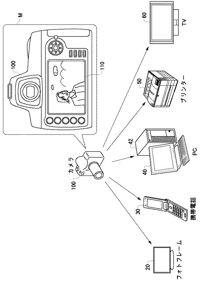
図1は、カメラ100が撮像した画像を変倍するシーンを示す概念図である。カメラ100は、撮像装置の一例としてのデジタルカメラである。本図のM部に示すように、カメラ100で撮像されて生成された撮像画像データは、撮像結果等をユーザに提示すべく、表示パネル等の表示部110に表示される。このとき、撮像画像データは、表示部110が画像表示に用いる画素数の画像データに変換される。多くの場合、撮像画像データは縮小されて表示部110に表示される。近年、撮像装置が有する撮像素子の有効画素数はますます高くなる。しかし、表示部110が有する画素数は大きく増えていないので、撮像画像データに対する縮小率は高くなる傾向にある。
FIG. 1 is a conceptual diagram illustrating a scene for scaling an image captured by the
また、カメラ100で生成された撮像画像データは、種々の画像出力機器を介して種々の出力媒体に出力される。例えば、撮像画像データは、画像出力機器の一例としてのデジタルフォトフレーム20、携帯電話端末30、パーソナルコンピュータ42、テレビ60等に出力され、各画像出力機器がそれぞれ有する表示パネルに出力される。撮像画像データは、表示パネルが表示に用いる画素数に従って縮小または拡大されて表示される。また、撮像画像データは、プリンタ50に出力され、プリンタ50が有するプリントヘッドのプリント解像度に応じた画素数に従って縮小または拡大されて、プリント媒体にプリントされる。画像出力機器としては、図示した機器の他、プロジェクタなどの投影装置等を例示することができる。
Also, captured image data generated by the
例えば、近年の撮像装置で撮像された高画素数の撮像画像データを、デジタルフォトフレーム20や、携帯電話端末30等で表示する場合、撮像画像データを大きく縮小して表示する必要がある。また、画素数が少ない画像データを、パーソナルコンピュータ42を用いてPCモニタ40に部分的に拡大するなどして表示する場合、画像データを大きく拡大して表示する必要がある。
For example, when high-capacity captured image data captured by a recent image capturing apparatus is displayed on the
線形補間や最近傍補間を用いて画像を縮小すると、エッジの高周波成分が残り易い。このため、くっきり感のある画像が得られるが、ジャギー等のノイズが出易い。例えば、変倍前の元画像に背景としてボカされて撮像された雲や山が、縮小処理によってくっきりしてしまうことがある。また、例えば空などの平坦な部分が写っている領域では、ショットノイズが目立つ場合がある。これらのノイズは、線形補間や最近傍補間よりフィルタ半径の大きい、例えばキュービック補間を縮小処理に用いることで目立ちにくくなる。しかし、さらに縮小率が大きくなった場合には、ノイズが目立ってしまう。一般に、フィルタ半径を大きくすると、ノイズは目立たなくなる。但しその際、縮小後の画像はボケてしまう。例えば、合焦して撮像された人物の髪がボケてしまい、撮像画像にあった髪のディテールが失われてしまう場合がある。拡大処理についても同様であり、一般にフィルタ半径を大きくとると拡大後の画像では、ジャギー等のノイズは減るが、画像はボケてしまう。一方、フィルタ半径を小さくするとボケは少なくなるが、元画像では目立たなかったノイズが強調されて不自然な画像になってしまう。 When the image is reduced using linear interpolation or nearest neighbor interpolation, the high-frequency component of the edge tends to remain. For this reason, a clear image can be obtained, but noise such as jaggy is likely to occur. For example, a cloud or a mountain that is blurred and picked up as a background in the original image before scaling may be sharpened by the reduction process. In addition, shot noise may be noticeable in a region where a flat part such as the sky is shown. These noises are less noticeable by using, for example, cubic interpolation having a larger filter radius than linear interpolation or nearest neighbor interpolation for reduction processing. However, when the reduction ratio is further increased, noise becomes conspicuous. In general, when the filter radius is increased, noise becomes inconspicuous. However, at that time, the reduced image is blurred. For example, the hair of a person captured in focus may be blurred, and the hair detail in the captured image may be lost. The same applies to the enlargement processing. Generally, when the filter radius is increased, noise such as jaggy is reduced in the enlarged image, but the image is blurred. On the other hand, when the filter radius is reduced, blurring is reduced, but noise that is not noticeable in the original image is emphasized, resulting in an unnatural image.
そのため、ノイズを低減しつつ、元画像が持つ自然なエッジ情報をきちんと変倍後の画像に反映させることが望まれる。また、PCモニタ40やデジタルフォトフレーム20を含む画像出力機器には、様々な画素数の画像が入力される場合がある。つまり、特定の変倍率だけでなく、様々な変倍率に対しても、元画像のエッジ情報をきちんと反映させる変倍処理が望まれる。
Therefore, it is desired that natural edge information of the original image is properly reflected in the image after scaling while reducing noise. In addition, an image output device including the
本実施形態では、ノイズを低減しつつ、元画像が持つ自然なエッジ情報をきちんと変倍後の画像に反映させる画像処理の一例について説明する。本実施形態では、カメラ100が撮像画像データを縮小して表示部110に表示する場合等、主として撮像画像データを縮小する場合を取り上げて、カメラ100の動作の一例を説明する。
In the present embodiment, an example of image processing in which natural edge information of an original image is properly reflected in an image after scaling while reducing noise will be described. In the present embodiment, an example of the operation of the
図2は、本実施形態に係るカメラ100のシステム構成図を示す。カメラ100は光学系101を備える。光学系101は、ズームレンズ、フォーカスレンズ等により構成される。被写体光は光軸に沿って光学系101に入射し、シャッタ102を通過して撮像素子103の受光面に被写体像として結像する。
FIG. 2 is a system configuration diagram of the
撮像素子103は、被写体像である光学像を光電変換する素子であり、例えば、CCD、CMOSセンサが用いられる。撮像素子103で光電変換された被写体像は、電荷として読み出されてアンプ部104でゲイン調整等がなされる。アンプ部104で増幅された信号は、アナログ信号としてA/D変換器105へ転送され、A/D変換器105でデジタル信号に変換される。撮像素子103の電荷読み出し、シャッタ102の駆動等の制御は、システム制御部114の同期制御を受けたタイミング発生部112が供給するクロック信号により制御される。
The
デジタル信号に変換された被写体像は、画像データとして順次処理される。A/D変換器105によりデジタル信号に変換された画像データは、画像処理部107へ引き渡されて処理される。具体的には、A/D変換器105によりデジタル信号に変換された画像データは、メモリ制御部106の制御により、内部メモリ108に一旦記憶される。内部メモリ108は、高速で読み書きのできるランダムアクセスメモリであり、例えばDRAM、SRAMなどが用いられる。内部メモリ108は、連写撮像、動画撮像において高速に連続して画像データが生成される場合に、画像処理の順番を待つバッファメモリとしての役割を担う。また、画像処理部107が行う画像処理、圧縮処理において、ワークメモリとしての役割も担う。したがって、内部メモリ108は、これらの役割を担うに相当する十分なメモリ容量を備える。メモリ制御部106は、いかなる作業にどれくらいのメモリ容量を割り当てるかを制御する。画像処理部107が行う画像処理としては、テンプレート画像等を用いた顔認識など、被写体認識の処理が含まれる。
The subject image converted into the digital signal is sequentially processed as image data. The image data converted into a digital signal by the A /
画像処理部107は、設定されている撮像モード、ユーザからの指示に従って、画像データを規格化された画像フォーマットの画像データに変換する。例えば、カメラ100の撮像モードの一部として静止画撮像モードおよび動画撮像モードを有しており、静止画撮像モードで静止画像としてJPEGファイルを生成する場合、画像処理部107は、色変換処理、ガンマ処理、ホワイトバランス補正等の画像処理を行った後に適応離散コサイン変換等を施して圧縮処理を行う。また、例えば動画撮像モードで動画像としてのMPEGファイル、H.264ファイルを生成する場合、画像処理部107は、生成された連続する静止画としてのフレーム画像に対して、フレーム内符号化、フレーム間符号化、量子化、エントロピー符号化等を施して圧縮処理を行う。フレーム間符号化には、動きベクトルを算出する処理が含まれる。
The
変換された画像データは再び内部メモリ108に保管される。画像処理部107によって処理された静止画像データ、動画像データは、システム制御部114の制御により、内部メモリ108から記録媒体IF111を介して、不揮発性メモリである記録媒体122に記録される。記録媒体122は、フラッシュメモリ等により構成される。記録媒体122は、カメラ100の本体に対して着脱可能な不揮発性メモリであってよい。
The converted image data is stored in the
画像処理部107は、記録用に処理される画像データに並行して、表示用の画像データを生成する。画像処理部107は、記録用に処理される画像データに並行して、後述する変倍処理を施すことによって表示用の画像データを生成する。生成された表示用の画像データは、表示制御部109の制御に従って、液晶パネル等で構成される表示部110に表示される。また、表示制御部109は、画像の表示と共に、もしくは画像を表示することなく、カメラ100の各種設定に関する様々なメニュー項目を、表示部110に表示することができる。カメラ100の各種設定に関する様々なメニュー項目としては、後述するエッジ強調の強度をユーザに指定させるためのメニュー項目が含まれる。また、縮小率をユーザに指定させるメニュー項目を含んでよい。
The
カメラ100は、上記の画像処理における各々の要素も含めて、システム制御部114により直接的または間接的に制御される。システム制御部114は、電気的に消去・記録可能な不揮発性メモリであるシステムメモリを有する。システムメモリは、EEPROM(登録商標)等により構成される。システム制御部114が有するシステムメモリは、カメラ100の動作時に必要な定数、変数、プログラム等を、カメラ100の非動作時にも失われないよう記録している。システム制御部114は、定数、変数、プログラム等を適宜内部メモリ108に展開して、カメラ100の制御に利用する。システムメモリには、後述する縮小率に対応づけられたフィルタ半径が、定数として記録されてよい。
The
カメラ100は、ユーザからの操作を受け付ける操作部材120を備えている。システム制御部114は、操作部材120が操作されたことを検知する。システム制御部114は、検出された操作に応じた動作を実行する。例えば、操作部材120としてのレリーズスイッチが操作されたことを検知したときには、システム制御部114は、被写体像を光電変換して画像データを生成する一連の撮像動作を実行する。操作部材120は、後述するエッジ強調の強度をユーザが指定するために用いられる。システム制御部114は、ユーザ操作に基づきエッジ強調の強度を設定して、設定した強度でエッジ強調されるよう画像処理部107を制御する。また、操作部材120は、縮小率をユーザが指定するために用いられる。システム制御部114は、ユーザ操作に基づき縮小率を設定して、設定した縮小率で撮像画像データを縮小するよう画像処理部107を制御する。
The
光学系101は、レンズ制御部113によって制御される。レンズ制御部113は、例えば、ユーザの指示に応じてズームレンズを駆動し、被写体像の画角を変更する。また、レンズ制御部113は、AF情報に基づいてフォーカスレンズを駆動し、被写体像を撮像素子103の受光面上で合焦させる。レンズ制御部113は、操作部材120等を通じてユーザによって指定された被写体に対して、オートフォーカスの制御を実行してよい。また、レンズ制御部113は、画像処理部107が処理した画像データまたは測光センサの出力を解析して露出値を算出する。レンズ制御部113は、算出した露出値に従って、光学系101が有する絞りの制御信号を出力する。
The
図3は、対象画像300に縮小処理を施して縮小画像を生成するまでの処理を模式的に表す。本処理は、特に断わらない限り、画像処理部107が主体として動作することで行われる。対象画像300は、例えば撮像素子103によって撮像され内部メモリ108に記憶された撮像画像データであり、縮小処理の対象となる画像である。例えば、対象画像300は、4928×3264画素等、1600万画素を超える画素数の画像データであってよい。一方、縮小後の画像は、例えば、900×600画素など、100万画素以下の画素数の画像データであってよい。縮小率は、対象画像300の画素数と、縮小画像360の画素数によって定まる。
FIG. 3 schematically illustrates processing until the reduced image is generated by performing the reduction process on the
画像処理部107は、キュービック補間を用いて、縮小後の画像と同じ画素数の第1画像310を対象画像300から生成する。また、画像処理部107は、ガウシアン補間を用いて、縮小後の画像と同じ画素数の第2画像320を対象画像300から生成する。
The
ガウシアン補間によると、元画像の低周波成分を主として反映した画像を得ることができる。一方、キュービック補間によれば、低周波成分だけでなく高周波成分も反映した画像を得ることができる。つまり、キュービック補間によれば、ガウシアン補間と比較して、ボケの小さい画像を得ることができる。縮小率が大きくなるほど多少のノイズが生じる場合があるが、キュービック補間によれば、対象画像300に含まれるエッジ成分を第1画像310に反映することができる。一方、ガウシアン補間によれば、対象画像300に含まれる高周波成分はあまり保存されないものの、第2画像320に生じるノイズを比較的に小さくすることができる。
According to Gaussian interpolation, an image that mainly reflects the low-frequency component of the original image can be obtained. On the other hand, according to cubic interpolation, an image reflecting not only a low frequency component but also a high frequency component can be obtained. That is, according to cubic interpolation, an image with less blur can be obtained compared to Gaussian interpolation. Some noise may occur as the reduction ratio increases, but according to cubic interpolation, the edge component included in the
本図において、対象画像300に含まれるエッジ情報を実線で模式的に示した。そして、第1画像310には、若干のボケを伴ってエッジ情報が反映された様子を一点鎖線で模式的に示した。また、第2画像320には、対象画像300の低周波成分が主として反映される様子を破線で模式的に示した。また、縮小処理により現れるノイズ量を、第1画像310および第2画像320内のドットの数で模式的に示した。すなわち、第1画像310と比較すると、第2画像320に含まれるノイズ量は比較的に少ない。
In the figure, edge information included in the
画像処理部107は、第1画像310から第2画像320を減算することにより、エッジ画像330を生成する。第1画像310には対象画像300の高周波および低周波が反映され、第2画像320には対象画像300の低周波成分が主として反映されているので、エッジ画像330は対象画像300に含まれるエッジを抽出したものとなる。具体的には、対象画像300に含まれるエッジの強さが、エッジ画像330の画素値に反映される。
The
画像処理部107は、エッジ量の強度を調整する強度調整マップ340を、エッジ画像330から生成する。強度調整マップ340は、エッジ画像330の各画素値に対応して、対応する画素値を補正する強度係数を持つ。具体的には、画像処理部107は、エッジ画像330の画素値の平均値を持つ画素点には強度係数を0とする。そして、平均値から離れる画素値を持つ画素点には、0より大きい強度係数を設定する。具体的には、エッジ画像330の画素値の平均値から離れるに従って大きくなる強度係数が設定される。
The
エッジ画像330に頻出する画素値の小さな画素は、縮小処理によって現れたノイズ成分である可能性が高い。一方、エッジ画像330にあまり現れない画素値の大きな画素は、対象画像300のエッジ成分を反映したものである可能性が高い。強度調整マップ340によると、エッジ画像330の画素値の平均値に近い画素値を持つ画素点には、小さな強度係数が設定される。本図の強度調整マップ340には、比較的に大きな強度係数がエッジ位置に設定された様子を実線で示し、その間の領域には比較的に小さな強度係数が設定された様子を空白で模式的に示す。
A pixel with a small pixel value that appears frequently in the
画像処理部107は、強度調整マップ340の各強度係数を、エッジ画像330の対応する画素値に乗算することにより、エッジ画像330を補正する。強度調整マップ340を乗算してエッジ画像330を補正することで、縮小処理によって生じたノイズを低減することができる。本図において、エッジ間のノイズが低減された様子を、補正後のエッジ画像350に模式的に示す。
The
そして、画像処理部107は、補正後のエッジ画像350を第1画像310に画素毎に加算することで、縮小画像360を生成する。縮小処理によるノイズが第1画像310に含まれている場合でも、エッジが加算されることで、ノイズの強度は相対的に低下する。本図において、ノイズの強度が相対的に低下した様子を、縮小画像360に模式的に示す。
Then, the
例えば対象画像を一旦縮小し、得られた縮小画像にエッジ強調処理を施す場合と比較すると、本縮小処理によれば、対象画像からのエッジ情報を用いてエッジ強調することができる。このため、ジャギー、疑似輪郭等のノイズや、撮像時のノイズが著しく強調されたりすることがなく、自然なエッジ強調を行うことができる。これは、エッジ成分である可能性が高い画素位置において強度係数を大きくすることで、ノイズをより低減することができるためである。このため、本縮小処理によれば、S/N比が高い縮小画像を得ることができる。 For example, as compared with a case where the target image is once reduced and edge enhancement processing is performed on the obtained reduced image, edge reduction can be performed using the edge information from the target image according to this reduction processing. For this reason, noise such as jaggies and pseudo contours and noise during imaging are not significantly emphasized, and natural edge enhancement can be performed. This is because noise can be further reduced by increasing the intensity coefficient at a pixel position that is highly likely to be an edge component. For this reason, according to this reduction process, a reduced image with a high S / N ratio can be obtained.
図4はカメラ100において縮小画像を生成する処理フローを示す。本フローは、撮像画像データが内部メモリ108に記憶された場合に、開始される。本処理フローにおいては、特に断わらない限り、画像処理部107が主体となって動作する。
FIG. 4 shows a processing flow for generating a reduced image in the
ステップS400で、撮像画像データに対する縮小率を決定する。縮小率は、例えば生成すべき縮小画像の対応する画素数を、撮像画像データの対応する一辺の画素数で除した値で決定される。 In step S400, a reduction ratio for the captured image data is determined. The reduction ratio is determined by, for example, a value obtained by dividing the number of pixels corresponding to the reduced image to be generated by the number of pixels corresponding to one side of the captured image data.
ステップS402で、キュービック補間のフィルタ半径、および、ガウシアン補間のフィルタ半径を決定する。例えば、システム制御部114のシステムメモリ内に、異なる縮小率に対応づけて異なるフィルタ半径が、補間種別毎に予め記録されており、画像処理部107は、システムメモリから内部メモリ108に展開された縮小率対フィルタ半径の情報を読み出す。そして、画像処理部107は、読み出した縮小率対フィルタ半径の情報に基づいて、ステップS400で決定した縮小率に対応するフィルタ半径を、キュービック補間およびガウシアン補間のそれぞれについて選択する。キュービック補間およびガウシアン補間で用いる補間係数については、図5に関連して後述される。
In step S402, a filter radius for cubic interpolation and a filter radius for Gaussian interpolation are determined. For example, different filter radii corresponding to different reduction ratios are recorded in advance in the system memory of the
ステップS404およびステップS406において、キュービック補間による縮小処理およびガウシアン補間による縮小処理を行う。本処理は、図3に関連して説明した第1画像310および第2画像320を生成する処理に対応する。
In step S404 and step S406, reduction processing by cubic interpolation and reduction processing by Gaussian interpolation are performed. This process corresponds to the process of generating the
ステップS408において、キュービック補間により生成された縮小画像と、ガウシアン補間により生成された縮小画像との差分処理により、エッジ画像を生成する。本処理は、図3に関連して説明した第1画像310から第2画像320を減算する処理に対応する。
In step S408, an edge image is generated by difference processing between the reduced image generated by cubic interpolation and the reduced image generated by Gaussian interpolation. This process corresponds to the process of subtracting the
ステップS410において、エッジ画像を場所毎に適応的に補正する。本処理は、図3に関連して説明した、エッジ画像330を補正してエッジ画像350を生成するまでの処理に対応する。本処理の詳細なフローについては、後述する。
In step S410, the edge image is adaptively corrected for each location. This processing corresponds to the processing until the
ステップS412において、キュービック補間により生成された縮小画像と、エッジ画像とを加算して、縮小画像を生成する。本処理は、図3に関連して説明した、第1画像310およびエッジ画像350から縮小画像360を生成する処理に対応する。ステップS412で生成した縮小画像は、内部メモリ108に一旦記憶され、種々の処理に供される。例えば、表示制御部109の制御により、縮小画像が表示部110に表示される。縮小画像は、記録媒体IF111を介して記録媒体122に記録されてもよい。また、画像認識用の画像として用いられてよい。また、縮小画像は、動画を構成するフレーム画像であってもよい。
In step S412, the reduced image generated by the cubic interpolation and the edge image are added to generate a reduced image. This process corresponds to the process of generating the reduced
ステップS414で、撮像画像データから他の縮小率の画像を生成するかを判断する。例えば、外部のデジタルフォトフレーム20等、外部の画像出力機器用の画像を生成するか否かを判断する。他の縮小率の画像を生成する場合、ステップS400に進む。予め定められた縮小画像のセットが生成されるまで、ステップS400からステップS412の処理を続ける。全ての縮小率の画像の生成が完了すると、一連の縮小画像の生成処理を終了する。
In step S414, it is determined whether to generate an image with another reduction ratio from the captured image data. For example, it is determined whether to generate an image for an external image output device such as the external
なお、ステップS412の加算処理において、エッジ画像の第1画像に対する加算比率は、ユーザ指示に基づきシステム制御部114が設定してよい。ユーザ指示は、例えば操作部材120を介してシステム制御部114が取得してよい。すなわち、システム制御部114は、ユーザ指示に基づいて、エッジ強調の強度を設定する強度設定部として機能する。そして、ステップS412において、画像処理部107は、設定された強度に基づいてエッジ画像の加算比率を変更して第1画像に加算することにより、縮小画像を生成する。
In the addition process in step S412, the addition ratio of the edge image to the first image may be set by the
また、ステップS412の加算処理において、エッジ強調の強度は縮小率に応じて設定されてよい。例えば、画像処理部107は、縮小率が小さいほど、すなわち縮小画像の画素数が多いほど、高い加算比率でエッジ画像を第1画像に加算することにより、縮小画像を生成してよい。ここではエッジ画像の加算比率を制御することでエッジ強調の強度を制御するとしたが、ステップS410でのエッジ画像の補正処理において、ユーザ指示または縮小率に応じてエッジ画像の強度を制御することで、エッジ強調の強度を制御してもよい。
In addition, in the addition processing in step S412, the edge enhancement strength may be set according to the reduction ratio. For example, the
なお、上記のステップS404およびステップS406の縮小処理は、順次に行ってよいが、少なくとも一部の処理が並行して行われてもよい。縮小処理を順次に行う場合、キュービック補間の縮小処理と、ガウシアン補間の縮小処理のいずれを先に行ってもよい。また、ステップS404、ステップS406およびステップS408に相当する処理を一括または並行して行ってもよい。例えば、縮小画像の1画素点について、キュービック補間による画素値の演算と、ガウシアン補間による画素値の演算と、画素値の差分の演算とを行う。この処理を、対象とする画素点を順次に変えて繰り返すことで、エッジ画像を生成してもよい。この態様の処理においても、キュービック補間およびガウシアン補間のそれぞれで各画素点の画素値を算出して、差分をとる処理が行われる。したがって、この態様の処理を実行することは、この発明における第1変倍処理部、第2変倍処理部、差分処理部の各処理を実行することに相当する。 In addition, although the reduction process of said step S404 and step S406 may be performed sequentially, at least one part process may be performed in parallel. When the reduction process is sequentially performed, either the cubic interpolation reduction process or the Gaussian interpolation reduction process may be performed first. In addition, the processing corresponding to step S404, step S406, and step S408 may be performed collectively or in parallel. For example, pixel value calculation by cubic interpolation, pixel value calculation by Gaussian interpolation, and pixel value difference calculation are performed for one pixel point of a reduced image. An edge image may be generated by repeating this process while sequentially changing the target pixel points. Also in the processing of this aspect, the pixel value of each pixel point is calculated by each of the cubic interpolation and the Gaussian interpolation, and processing for obtaining a difference is performed. Therefore, executing the processing of this aspect is equivalent to executing each processing of the first scaling processing unit, the second scaling processing unit, and the difference processing unit in the present invention.
図5は、キュービック補間に用いる補間係数f(x)の関数形状の一例を示す。補間係数f(x)は、下記の式(11)で表される。 FIG. 5 shows an example of the function shape of the interpolation coefficient f (x) used for cubic interpolation. The interpolation coefficient f (x) is expressed by the following equation (11).
式(11)において、係数αおよびβは、f(x)の関数形状を定めるパラメータであり、−3<α<0および0<β<−2αを満たすとする。xは、補間位置を基準とした、補間演算に用いる画素位置の相対的な座標値を示す。本図のf(x)は、α=−0.8、β=−0.3の場合の補間係数である。 In equation (11), coefficients α and β are parameters that determine the function shape of f (x), and assume that −3 <α <0 and 0 <β <−2α are satisfied. x represents a relative coordinate value of the pixel position used for the interpolation calculation based on the interpolation position. In the figure, f (x) is an interpolation coefficient when α = −0.8 and β = −0.3.
本補間係数を用いた演算では、フィルタ半径は3となる。式(11)においてβ=0としたものが、一般に良く知られたフィルタ半径が2のキュービック補間係数に相当する。キュービック補間であっても、フィルタ半径が2の補間係数を用いると、縮小率が大きくなるにつれて、最近傍補間と同様の結果となる場合がある。つまり、縮小率が大きくなるにつれて、ジャギー等のノイズが目立つようになる。ノイズを避けるためにフィルタ半径を縮小率に応じて拡大した補間係数を用いると、ジャギーが目立たなくなるが、ボケた画像になってしまう場合がある。 In the calculation using this interpolation coefficient, the filter radius is 3. In Equation (11), β = 0 corresponds to a well-known cubic interpolation coefficient having a filter radius of 2. Even in the case of cubic interpolation, if an interpolation coefficient having a filter radius of 2 is used, the result may be the same as that of nearest neighbor interpolation as the reduction ratio increases. That is, as the reduction ratio increases, noise such as jaggy becomes conspicuous. If an interpolation coefficient obtained by enlarging the filter radius according to the reduction ratio in order to avoid noise is used, jaggy is not noticeable, but a blurred image may occur.
本補間係数f(x)によれば、フィルタ半径を3に拡張でき、補間関数をより理想的な形状に近づけることができる。したがって、ボケが少なくノイズも小さい縮小画像を得ることができる。なお、本補間係数f(x)で縮小処理する場合でも、縮小率に応じてフィルタ半径を大きくしてもよい。具体的には、縮小率が大きいほど、フィルタ半径を拡大してよい。この場合でも、フィルタ半径が2のキュービック補間を適用する場合と比較して、ボケの小さい縮小画像を得ることができる。 According to this interpolation coefficient f (x), the filter radius can be expanded to 3, and the interpolation function can be made closer to an ideal shape. Accordingly, a reduced image with less blur and less noise can be obtained. Even when the reduction process is performed with the interpolation coefficient f (x), the filter radius may be increased according to the reduction rate. Specifically, the filter radius may be increased as the reduction ratio increases. Even in this case, a reduced image with small blur can be obtained as compared with the case where cubic interpolation with a filter radius of 2 is applied.
本図では、キュービック補間の補間係数として、フィルタ半径が3の補間係数を例示した。しかし、フィルタ半径は3に限られず、2を超える大きさのフィルタ半径を持つキュービック補間を適用してよい。例えば、フィルタ半径が4の補間係数f(x)は、下記の式(12)で表される。 In this figure, an interpolation coefficient having a filter radius of 3 is illustrated as an interpolation coefficient for cubic interpolation. However, the filter radius is not limited to 3, and cubic interpolation having a filter radius larger than 2 may be applied. For example, an interpolation coefficient f (x) having a filter radius of 4 is expressed by the following equation (12).
式(12)において、係数α、β、γは、f(x)の関数形状を定めるパラメータであり、−3<α<0、0<β<−2α、および、−2β<γ<0を満たすとする。 In Expression (12), coefficients α, β, and γ are parameters that determine the function shape of f (x), and −3 <α <0, 0 <β <−2α, and −2β <γ <0. Satisfy.
本実施形態の縮小処理では、ジャギー等のノイズが目立ちにくく、ボケも比較的に小さい縮小処理として、上述したキュービック補間による縮小処理を適用して、第1画像を生成する。一方、対象画像にガウシアン補間法による縮小処理を適用することで、ジャギー等のノイズが小さくボケが比較的に大きい第2画像を生成する。ガウシアン補間の補間係数g(x)は、下記の式(13)で表される。 In the reduction process of the present embodiment, noise such as jaggy is not noticeable and the first image is generated by applying the above-described reduction process by cubic interpolation as a reduction process with relatively small blur. On the other hand, by applying a reduction process by the Gaussian interpolation method to the target image, a second image with a small noise such as jaggy and a relatively large blur is generated. The interpolation coefficient g (x) for Gaussian interpolation is expressed by the following equation (13).
式(13)において、Aは規格化定数で、重み係数が合計して1になるように設定される。フィルタ半径は、式(13)のσによって制御することができる。ガウシアン補間のフィルタ半径として、キュービック補間のフィルタ半径と同等のフィルタ半径を適用すると、ボケが比較的に大きくなってしまう。そこで、σの値として、縮小率の0.5倍の値を適用してよい。 In Equation (13), A is a normalization constant, and is set so that the weighting factors are 1 in total. The filter radius can be controlled by σ in equation (13). When a filter radius equal to the filter radius of cubic interpolation is applied as the filter radius of Gaussian interpolation, blurring becomes relatively large. Therefore, a value of 0.5 times the reduction ratio may be applied as the value of σ.
画像処理部107は、式(11)または式(12)に例示したような、補間半径が2画素分の長さを超えるキュービック補間を適用して、第1画像を生成する。但し、補間半径が2画素分の長さを超えるキュービック補間を適用するか否かは、縮小率に応じて設定してもよい。具体的には、ステップS402において、画像処理部107は、縮小率が予め定められた基準変倍率以下の場合に、2画素分の補間半径を持つ通常のキュービック補間を適用し、縮小率が基準変倍率を超える場合に、補間半径が2画素分を超えるキュービック補間を適用する。
The
図6は、エッジ画像を適応的に補正する処理フローの一例を示す。本処理フローは、図4のステップS410の内部処理を示す。本処理フローにおいては、特に断わらない限り、画像処理部107が主体となって動作する。
FIG. 6 shows an example of a processing flow for adaptively correcting an edge image. This processing flow shows the internal processing of step S410 in FIG. In this processing flow, the
ステップS610において、エッジ画像を解析してエッジ画像の特徴量を算出する。具体的には、エッジ画像の全画素の平均値および標準偏差を、特徴量として算出する。これにより、エッジ画像の強度分布を解析することが可能になる。 In step S610, the edge image is analyzed to calculate the feature amount of the edge image. Specifically, the average value and standard deviation of all the pixels of the edge image are calculated as the feature amount. This makes it possible to analyze the intensity distribution of the edge image.
ステップS620において、エッジ画像から強度調整マップを生成する。強度調整マップは、エッジ画像に含まれる複数の画素のそれぞれに対応する複数の強度係数を含む。本処理は、図3に関連して説明した強度調整マップ340の各強度係数を算出する処理に対応する。本処理により、エッジ画像の強度分布およびエッジ画像の画素値に応じて、エッジ成分である可能性の高い場所の強調係数を大きくし、ノイズ成分である可能性の高い場所の強調係数を小さくした強度調整マップが生成される。より具体的には、画像処理部107は、特徴量により定まるエッジ強調関数を用いてエッジ画像の画素値から強度係数を算出する。エッジ強調関数については後述する。
In step S620, an intensity adjustment map is generated from the edge image. The intensity adjustment map includes a plurality of intensity coefficients corresponding to each of a plurality of pixels included in the edge image. This process corresponds to the process of calculating each intensity coefficient of the
ステップS630において、ステップS620で算出された強度調整マップを平滑化する。一例として、画像の縦方向および横方向に画素を平均化するローパスフィルタにより、強度調整マップを平滑化する。これにより、エッジ成分であるが正規化した画素値が小さい画素およびノイズ成分であるが正規化した画素値が大きい画素等のイレギュラーな画素の強調係数を、周囲の画素の強調係数に基づき補正することができる。 In step S630, the intensity adjustment map calculated in step S620 is smoothed. As an example, the intensity adjustment map is smoothed by a low-pass filter that averages pixels in the vertical and horizontal directions of the image. This makes it possible to correct the enhancement factors of irregular pixels, such as pixels that have edge components but a small normalized pixel value, and pixels that are noise components but have a large normalized pixel value, based on the enhancement factors of surrounding pixels. can do.
この場合、ローパスフィルタのぼかし強度を上げてフィルタリングをする事で強度調整マップの画素間の相関強度を強くすることができ、ぼかし強度を下げてフィルタリングをすることで強度調整マップの画素間の相関強度を弱くすることができる。そこで、一例として、[1,2,1]/4等のローパスフィルタをn回掛け、nを変更可能とする。これにより、強度調整マップの画素間の相関強度を調整することができる。nの値は、ユーザ指示に基づいて設定されてよい。 In this case, you can increase the correlation strength between pixels of the intensity adjustment map by increasing the blur strength of the low-pass filter, and increase the correlation strength between the pixels of the intensity adjustment map by decreasing the blur strength. The strength can be reduced. Therefore, as an example, a low pass filter such as [1, 2, 1] / 4 is applied n times so that n can be changed. Thereby, the correlation strength between the pixels of the strength adjustment map can be adjusted. The value of n may be set based on a user instruction.
ステップS640において、強度調整マップによりエッジ画像を補正する。一例として、エッジ画像に含まれる複数の画素のそれぞれに、強度調整マップの対応する強調係数を乗算することにより、エッジ画像を補正する。これにより、ノイズ成分等の画素に対応する画素値を小さくすることができる。ステップS640の処理を終えると、本処理フローは終了する。 In step S640, the edge image is corrected by the intensity adjustment map. As an example, the edge image is corrected by multiplying each of the plurality of pixels included in the edge image by a corresponding enhancement coefficient of the intensity adjustment map. Thereby, the pixel value corresponding to pixels, such as a noise component, can be made small. When the process of step S640 is completed, this process flow ends.
本フロー図に関連して説明したように、画像処理部107は、エッジ画像を解析してエッジ画像の特徴量を算出する特徴量算出部、画像内の場所毎に異なるエッジ強調の強度を設定する強度調整マップを、特徴量に基づいてエッジ画像から算出するマップ算出部、エッジ画像を強度調整マップにより補正するエッジ補正処理部として機能する。そして、画像処理部107は、第1画像と、補正されたエッジ画像とから、縮小画像を生成する変倍画像生成部として機能する。強度調整マップを生成する処理は、図7に関連して説明される。
As described in connection with this flowchart, the
図7は、強度調整マップの強度係数を算出するためのエッジ強調関数の一例を示す。エッジ強調関数は、正規化された画素値を入力とし、強度係数を出力する関数である。正規化された画素値は、特徴量である平均値および標準偏差に基づく正規化関数により算出される。エッジ強調関数は、正規化された画素値を入力値とし、入力値が0の近傍において小さく、0から離れるに従い大きい出力値を出力する。すなわち、エッジ強調関数は、正規化関数と、入力値に応じて出力値を定める基準エッジ強調関数とに分解される。具体的には、正規化関数は、下記の式(14)のように表される。 FIG. 7 shows an example of an edge enhancement function for calculating the intensity coefficient of the intensity adjustment map. The edge enhancement function is a function that receives a normalized pixel value as an input and outputs an intensity coefficient. The normalized pixel value is calculated by a normalization function based on the average value and standard deviation which are feature amounts. The edge enhancement function takes a normalized pixel value as an input value, outputs an output value that is small when the input value is near 0 and increases as the distance from 0 is increased. That is, the edge enhancement function is decomposed into a normalization function and a reference edge enhancement function that determines an output value according to an input value. Specifically, the normalization function is expressed as the following formula (14).
式(14)において、Xは、正規化された画素値を表す。fは、エッジ画像の元の画素値を表す。fの上にバーが付された値は、エッジ画像の画素値の平均値を表す。σは、エッジ画像の標準偏差を表す。すなわち、正規化関数は、画素値から平均値を減じた偏差を、標準偏差で除算する関数である。 In Expression (14), X represents a normalized pixel value. f represents the original pixel value of the edge image. A value with a bar on f represents an average value of the pixel values of the edge image. σ represents the standard deviation of the edge image. That is, the normalization function is a function that divides the deviation obtained by subtracting the average value from the pixel value by the standard deviation.
画像処理部107は、エッジ画像に含まれる複数の画素のそれぞれの画素値を、本正規化関数により正規化する。つまり、画像処理部107は、エッジ画像の各画素値を特徴量により正規化する正規化部として機能する。具体的には、画像処理部107は、エッジ画像に含まれる複数の画素のそれぞれに対して、画素値から平均値を減じた偏差を標準偏差で除算することにより、エッジ画像の各画素値を正規化する。このように正規化された各画素値は、元の画素値が平均値に一致する場合には0となり、元の画素値が平均値から正側に標準偏差分離れた場合には1、元の画素値が平均値から負側に標準偏差分離れた場合には−1となる。画像処理部107は、式(14)を用いて、エッジ画像の画素値を典型的なスケールで正規化することで、任意の画像に対してISO(International Organization for Standardization)感度等の撮像条件の依存性が少ない値に変換できる。
The
基準エッジ強調関数は、正規化関数により正規化された画素値を入力値とし、入力値が0の近傍において出力値が小さく、0から離れるに従い出力値が大きくなる関数である。さらに、基準エッジ強調関数は、0から一定範囲以上離れたことに応じて、出力値が予め定められた値に漸近またはクリップする事が望ましい。例えば、基準エッジ強調関数は、下記の式(15)のように表される。 The reference edge enhancement function is a function in which a pixel value normalized by a normalization function is used as an input value, the output value is small when the input value is near 0, and the output value increases as the distance from 0 is increased. Furthermore, it is desirable that the reference edge enhancement function is asymptotic or clipped to a predetermined value in accordance with the distance from 0 being a certain range or more. For example, the reference edge enhancement function is expressed as the following equation (15).
式(15)において、Xは、正規化された画素値を表す。Iは、出力値を表す。すなわち、基準エッジ強調関数は、入力値の2の自然数倍のべき乗(例えば4のべき乗)に比例した値を、入力値の2の自然数倍のべき乗(例えば4のべき乗)に比例した値と正定数とを加算した値により除算した出力値を出力する関数である。 In Expression (15), X represents a normalized pixel value. I represents an output value. That is, the reference edge enhancement function is a value proportional to a power of 2 times the natural number of the input value (for example, a power of 4), and a value proportional to a power of 2 times the natural number of the input value (for example, the power of 4). And a function that outputs an output value obtained by dividing by a value obtained by adding a positive constant.
画像処理部107は、エッジ画像に含まれる複数の画素のそれぞれに対して、本基準エッジ強調関数により強調係数を算出して強度調整マップを生成する。つまり、画像処理部107は、正規化された各画素値を入力とし、入力した画素値を予め定められた基準エッジ強調関数により強調係数に変換した強度調整マップを生成する変換処理部として機能する。具体的には、画像処理部107は、エッジ画像に含まれる複数の画素のそれぞれに対して、正規化された画素値の2の自然数倍のべき乗に比例した値を、正規化された画素値の2の自然数倍のべき乗に比例した値と正定数とを加算した値により除算した出力値を出力する基準エッジ強調関数により強調係数を算出して、強度調整マップを生成する。
The
このように算出された強調係数は、図7のBに示されるように、正規化された画素値が0の近傍の場合に小さく(例えば0)、0から離れるに従い大きくなる。さらに、このように算出された強調係数は、正規化された画素値が0から一定以上離れた場合に、予め定められた値(例えば1)に漸近的に収束する。 The enhancement coefficient calculated in this way is small (for example, 0) when the normalized pixel value is in the vicinity of 0, as shown in FIG. 7B, and increases as the distance from 0 is increased. Furthermore, the enhancement coefficient calculated in this way converges asymptotically to a predetermined value (for example, 1) when the normalized pixel value is more than a certain distance from 0.
ここで、カメラ100により撮像された画像のエッジ画像において、正規化された画素値の頻度分布は、一例として、本図の線Aに表されるようになる。すなわち、正規化された画素値の頻度分布は、正規化された画素値が0に近い範囲においてピークとなり、正規化された画素値が0から離れるに従って小さくなる。
Here, in the edge image of the image captured by the
撮像された画像におけるエッジ画像において、典型的な画素値より絶対値の十分小さい画素はエッジ成分ではない場合が多く、また、典型的な画素値より絶対値が十分大きい画素は本来のエッジ成分である場合が多い。すなわち、正規化された画素値が0の近傍の画素はノイズ成分である場合が多く、正規化された画素値が0から一定範囲以上離れた画素はエッジ成分である場合が多い。 In an edge image in a captured image, a pixel whose absolute value is sufficiently smaller than a typical pixel value is often not an edge component, and a pixel whose absolute value is sufficiently larger than a typical pixel value is an original edge component. There are many cases. That is, a pixel in the vicinity where the normalized pixel value is 0 is often a noise component, and a pixel whose normalized pixel value is away from 0 by a certain range or more is often an edge component.
したがって、画像処理部107は、正規化関数および基準エッジ強調関数により強度調整マップを生成することにより、エッジ成分である可能性の高い画素に対応する強調係数を大きくし、ノイズ成分である可能性の高い画素に対応する強調係数を小さくした強度調整マップを生成することができる。
Therefore, the
本強度調整マップを用いてエッジ画像を補正することで、エッジ画像に含まれるノイズ成分を低減することができる。そして、キュービック補間で生成された縮小画像に、補正されたエッジ画像を加算することで、対象画像に写り込んだ被写体に関わらず、エッジを適切に強調することができる。これにより、人間の経験に応じた強調パラメータの設定等を必要とせずに、違和感の無く自然に被写体の輪郭をくっきりさせることができる。 By correcting the edge image using the intensity adjustment map, it is possible to reduce noise components included in the edge image. Then, by adding the corrected edge image to the reduced image generated by the cubic interpolation, the edge can be appropriately emphasized regardless of the subject reflected in the target image. Thereby, the outline of the subject can be naturally sharpened without the need for setting an emphasis parameter according to human experience and the like.
なお、画像処理部107は、ステップS610において、式(15)に代えて、下記の式(16)に表される基準エッジ強調関数により強度調整マップを生成してもよい。
In step S610, the
式(16)において、Xは、正規化された画素値を表す。Iは、出力値を表す。すなわち、式(16)において、基準エッジ強調関数は、入力値の2の自然数倍のべき乗(例えば4のべき乗)に比例した値を、入力値の2の自然数倍のべき乗(例えば4のべき乗)に比例した値と第1の正定数とを加算した値により除算した値を算出し、さらに、除算した値から第2の正定数を減算した出力値を出力する関数である。 In Expression (16), X represents a normalized pixel value. I represents an output value. That is, in the equation (16), the reference edge enhancement function calculates a value proportional to a power of 2 times the natural number of the input value (for example, a power of 4) as a power of 2 times the natural value of the input value (for example, of 4). This is a function for calculating a value obtained by dividing a value proportional to a power) and a value obtained by adding a first positive constant, and outputting an output value obtained by subtracting the second positive constant from the divided value.
このように算出された強調係数は、図7のCに示されるように、正規化された画素値が0の近傍の場合に負の値となり、0から離れるに従い大きくなる。さらに、このように算出された強調係数は、正規化された画素値が0から一定以上離れた場合に、予め定められた正の値(例えば1)に漸近的に収束する。 The enhancement coefficient calculated in this way becomes a negative value when the normalized pixel value is in the vicinity of 0, as shown in FIG. 7C, and increases as the distance from 0 increases. Further, the enhancement coefficient calculated in this manner asymptotically converges to a predetermined positive value (for example, 1) when the normalized pixel value is more than a certain distance from 0.
したがって、本関数により算出された強度調整マップを対象画像に加算した場合、正規化された画素値が0の近傍の画素では、符号を反転させたエッジ量を加算することで、対象画像にボケを生じさせることができる。これにより、ノイズ成分が含まれる可能性の高い画素にボケを与えて、エッジ成分ではないノイズ成分の平滑化ができる。一般的に、正規化されていないエッジ成分を用いた判断で同様の処理を行うと、ノイズ成分だけでなくエッジ強度の弱いエッジ部分も平滑化されてしまう場合がある。しかし、ステップ640で正規化されたエッジ成分と、強度調整マップを調整する事で、周囲に強いエッジ成分が存在する弱いエッジ部分でも、誤ってボカされる事が無く正しくエッジ強調をすることが可能になる。
Therefore, when the intensity adjustment map calculated by this function is added to the target image, for pixels in the vicinity where the normalized pixel value is 0, the edge amount with the sign inverted is added to add blur to the target image. Can be generated. As a result, it is possible to blur a pixel that has a high possibility of including a noise component, and to smooth a noise component that is not an edge component. In general, when the same processing is performed by using a non-normalized edge component, not only a noise component but also an edge portion having a weak edge strength may be smoothed. However, by adjusting the edge component normalized in
以上の説明において、対象画像を縮小する縮小処理において、キュービック補間およびガウシアン補間を用いるとした。具体的には、画像処理部107が、キュービック補間を適用して第1画像を生成し、ガウシアン補間を適用して第2画像を生成するとして説明した。しかし、縮小手法は、キュービック補間法およびガウシアン補間法に限られず、ぼかし度合いが異なる2以上の補間方法を適用することができる。縮小率が比較的に小さい場合、ぼかし度合いが小さい方の補間方法として線形補間を適用することができる場合がある。また、同じ補間法を用いるか否かに関係なく、フィルタ半径が異なる補間法を、ぼかし度合いが異なる2以上の補間方法として適用してもよい。ぼかし度合いが小さい補間方法として、例えばジャギなどのノイズが少なく対象画像からエッジ成分をきちんと抽出できることが望ましいことは言うまでもない。しかし、ぼかし度合いが異なる補間方法を用いることで、対象画像から直接に得たエッジ情報をエッジ強調処理において利用することが可能になる。また、例えば1つの補間方法で縮小した画像に対してエッジ強調をする場合と比較して、より高周波のエッジ成分を抽出することができる。
In the above description, cubic interpolation and Gaussian interpolation are used in the reduction processing for reducing the target image. Specifically, it has been described that the
上記においては、主として縮小処理を取り上げて本実施形態に係る画像処理を説明した。具体的には、画像処理部107は、対象画像を予め定められた縮小率で縮小した第1画像と、対象画像を予め定められた縮小率で縮小した第2画像とを生成して、第1画像および第2画像を用いて、対象画像を縮小した変倍画像を生成するとした。しかし、同様の画像処理を拡大処理にも適用することができる。キュービック補間のようなぼかし度合いの小さい拡大手法と、ガウシアン補間のようなノイズが少ない拡大手法とを適用することで、対象画像からエッジを適切に抽出することができる。つまり、以上に説明した画像処理は、画素数を低減する縮小処理だけでなく、画素数を増加する拡大処理にも適用することができる。すなわち、以上に説明した画像処理を、対象する画像を変倍した変倍画像を生成する場合に適用することができる。
In the above, the image processing according to the present embodiment has been described mainly by taking the reduction processing. Specifically, the
すなわち、画像処理部107は、対象画像を予め定められた変倍率で変倍した第1画像を生成する第1変倍処理部、第1画像を生成する変倍処理とは異なる変倍処理を用いて対象画像を予め定められた変倍率で変倍して、第1画像よりもボケた第2画像を生成する第2変倍処理部、第1画像と第2画像との差分処理により、エッジ画像を生成する差分処理部、第1画像とエッジ画像とから、変倍画像を生成する変倍画像生成部として機能することができる。
That is, the
上記において、エッジ画像の画素値の平均値および標準偏差σを特徴量として用いて、エッジ画像を正規化するとした。すなわち、画像処理部107は、エッジ画像に含まれる複数の画素の画素値の平均値および標準偏差を、特徴量として算出するとした。しかし、エッジ画像の画素値の分布に対する各画素値の位置を評価できる指標値であれば、どのような指標値を特徴量として用いてもよい。例えば、エッジ画像の典型的な画素値を表す特徴量としては、画素値の平均値に代えて、画素値のヒストグラムにおいて頻度が最大となる画素値を用いることができる。
In the above description, the edge image is normalized by using the average value of the pixel values of the edge image and the standard deviation σ as the feature amount. That is, the
既に説明したように、本実施形態にかかる変倍処理は、カメラ100において表示部110に表示される画像を生成する処理に適用することができる。例えば、表示部110は、撮像素子103が画像信号として出力した対象画像から生成された縮小画像を表示する。表示部110に表示される画像として、ライブビュー画像、サムネイル画像、記録済みの画像をユーザに提示するための表示用画像などを例示することができる。また、本実施形態にかかる変倍処理を、記録用の画像を生成する場合にも適用できる。例えば、撮像素子103で撮像されたものを動画として記録する場合、撮像素子103で撮像された画像を、撮像素子103の有効画素数よりも少ない画素数のフレーム画像に縮小する場合がある。画像処理部107は、このフレーム画像に縮小する場合の処理に、本実施形態にかかる縮小処理を適用してよい。すなわち、画像処理部107は、撮像素子103が画像信号として出力した対象画像から生成された複数の変倍画像から、動画を生成する動画生成部として機能する。
As already described, the scaling process according to the present embodiment can be applied to a process of generating an image displayed on the
また、本実施形態にかかる変倍処理によれば、ノイズが低減された変倍画像を提供できる。したがって、本変倍画像は、画像のマッチング処理に適する。画像のマッチング処理としては、動画圧縮用の動きベクトルを算出するためのブロックマッチング処理を例示することができる。具体的には、画像処理部107は、動画を構成する複数の変倍画像からブロックマッチングにより動きベクトルを算出して、算出した動きベクトルを用いて動画を圧縮してよい。すなわち、画像処理部107は、複数の対象画像から生成された複数の縮小画像から、複数の変倍画像で構成される動画を圧縮するための動きベクトルを算出する動きベクトル算出部、算出した動きベクトルを用いて動画を圧縮する圧縮部として機能することができる。
Further, according to the scaling process according to the present embodiment, a scaled image with reduced noise can be provided. Therefore, the zoomed image is suitable for image matching processing. As an image matching process, a block matching process for calculating a motion vector for moving image compression can be exemplified. Specifically, the
また、画像のマッチング処理としては、人物の顔を識別する処理を例示することができる。ノイズの少ない変倍画像を顔識別処理に用いることで、人物の顔を正確に識別することが可能になる。顔識別処理に用いる変倍画像とは、テンプレートマッチングに用いるテンプレート画像であってよいし、テンプレート画像等を用いたマッチング処理の対象となる識別対象画像であってもよい。画像処理部107は、撮像画像としての対象画像から、テンプレート画像および識別対象画像の少なくとも一方としての変倍画像を生成して、生成した変倍画像を用いて画像認識により人物の顔の識別処理を実行してよい。すなわち、画像処理部107は、変倍画像を用いて、画像認識により人物の顔を識別する識別処理部として機能することができる。なお、本識別処理の対象は、人物の顔に限られない。本識別処理は、動物、車両のナンバープレート等の種々の被写体を対象とすることができる。
Further, as an image matching process, a process of identifying a person's face can be exemplified. By using a variable-magnification image with less noise for face identification processing, it is possible to accurately identify the face of a person. The scaled image used for the face identification process may be a template image used for template matching or an identification target image that is a target of matching processing using a template image or the like. An
上記実施形態で説明したカメラ100は、レンズ交換式一眼レフカメラ、コンパクトデジタルカメラ、ミラーレス一眼カメラおよびビデオカメラ等はもちろん、カメラ機能付きの携帯電話等に適用できる。また、上記において、上記の変倍処理が、主としてカメラ100で行われるとして説明した。しかし、当該変倍処理を、デジタルフォトフレーム20、携帯電話端末30、パーソナルコンピュータ42、プリンタ50、テレビ60が行うことができる。
The
カメラ100、デジタルフォトフレーム20、携帯電話端末30、パーソナルコンピュータ42、プリンタ50、テレビ60は、変倍処理の実行を制御する制御プログラムをプロセッサが実行することで、当該変倍処理を実行してよい。パーソナルコンピュータ42等のように、外部の記録媒体からプログラムを読み込むことができる電子情報処理装置においては、制御プログラムを記憶しているコンピュータ読取可能な記録媒体を読み込むことによって制御プログラムをロードしてよい。
The
以上、本発明を実施の形態を用いて説明したが、本発明の技術的範囲は上記実施の形態に記載の範囲には限定されない。上記実施の形態に、多様な変更または改良を加えることが可能であることが当業者に明らかである。その様な変更または改良を加えた形態も本発明の技術的範囲に含まれ得ることが、特許請求の範囲の記載から明らかである。 As mentioned above, although this invention was demonstrated using embodiment, the technical scope of this invention is not limited to the range as described in the said embodiment. It will be apparent to those skilled in the art that various modifications or improvements can be added to the above-described embodiment. It is apparent from the scope of the claims that the embodiments added with such changes or improvements can be included in the technical scope of the present invention.
特許請求の範囲、明細書、および図面中において示した装置、システム、プログラム、および方法における動作、手順、ステップ、および段階等の各処理の実行順序は、特段「より前に」、「先立って」等と明示しておらず、また、前の処理の出力を後の処理で用いるのでない限り、任意の順序で実現しうることに留意すべきである。特許請求の範囲、明細書、および図面中の動作フローに関して、便宜上「まず、」、「次に、」等を用いて説明したとしても、この順で実施することが必須であることを意味するものではない。 The order of execution of each process such as operations, procedures, steps, and stages in the apparatus, system, program, and method shown in the claims, the description, and the drawings is particularly “before” or “prior to”. It should be noted that the output can be realized in any order unless the output of the previous process is used in the subsequent process. Regarding the operation flow in the claims, the description, and the drawings, even if it is described using “first”, “next”, etc. for convenience, it means that it is essential to carry out in this order. It is not a thing.
20 デジタルフォトフレーム、30 携帯電話端末、40 PCモニタ、42 パーソナルコンピュータ、50 プリンタ、60 テレビ、100 カメラ、101 光学系、102 シャッタ、103 撮像素子、104 アンプ部、105 A/D変換器、106 メモリ制御部、107 画像処理部、108 内部メモリ、109 表示制御部、110 表示部、111 記録媒体IF、112 タイミング発生部、113 レンズ制御部、114 システム制御部、120 操作部材、122 記録媒体、300 対象画像、310 第1画像、320 第2画像、330 エッジ画像、340 強度調整マップ、350 エッジ画像、360 縮小画像
20 Digital Photo Frame, 30 Mobile Phone Terminal, 40 PC Monitor, 42 Personal Computer, 50 Printer, 60 Television, 100 Camera, 101 Optical System, 102 Shutter, 103 Image Sensor, 104 Amplifier Unit, 105 A / D Converter, 106
Claims (16)
前記対象画像データを予め定められた変倍率で変倍した第1画像データを生成する第1変倍処理部と、
前記第1画像データを生成する変倍処理とは異なる変倍処理を用いて前記対象画像データを前記予め定められた変倍率で変倍して、前記第1画像データよりもボケた第2画像データを生成する第2変倍処理部と、
前記第1画像データと前記第2画像データとの差分処理により、エッジ画像データを生成する差分処理部と、
前記第1画像データと前記エッジ画像データとから、前記変倍画像データを生成する変倍画像生成部と
を備える画像処理装置。 An image processing device for generating scaled image data obtained by scaling target image data,
A first scaling unit that generates first image data obtained by scaling the target image data at a predetermined scaling factor;
A second image that is more blurred than the first image data by scaling the target image data at the predetermined scaling factor using a scaling process different from the scaling process for generating the first image data. A second scaling unit for generating data;
A difference processing unit that generates edge image data by a difference process between the first image data and the second image data;
An image processing apparatus comprising: a scaled image generation unit that generates the scaled image data from the first image data and the edge image data.
画像内の場所毎に異なるエッジ強調の強度を設定する強度調整マップを、前記特徴量に基づいて前記エッジ画像データから算出するマップ算出部と、
前記エッジ画像データを前記強度調整マップにより補正するエッジ補正処理部と
をさらに備え、
前記変倍画像生成部は、前記第1画像データと、前記補正された前記エッジ画像データとから、前記変倍画像データを生成する
請求項1に記載の画像処理装置。 A feature amount calculation unit that analyzes the edge image data and calculates a feature amount of the edge image;
An intensity adjustment map for setting different edge enhancement intensity for each location in the image, a map calculation unit for calculating from the edge image data based on the feature amount;
An edge correction processing unit that corrects the edge image data with the intensity adjustment map;
The image processing apparatus according to claim 1, wherein the scaled image generation unit generates the scaled image data from the first image data and the corrected edge image data.
請求項2に記載の画像処理装置。 The image processing apparatus according to claim 2, wherein the feature amount calculation unit calculates an average value and a standard deviation of a plurality of pixels included in the edge image data as the feature amount.
前記エッジ画像の各画素値を前記特徴量により正規化する正規化部と、
正規化された各画素値を入力とし、入力した画素値を予め定められた基準エッジ強調関数により強調係数に変換した前記強度調整マップを生成する変換処理部と
を有する請求項3に記載の画像処理装置。 The map calculation unit
A normalization unit for normalizing each pixel value of the edge image with the feature amount;
The image according to claim 3, further comprising: a conversion processing unit that receives each normalized pixel value as input and generates the intensity adjustment map obtained by converting the input pixel value into an enhancement coefficient by a predetermined reference edge enhancement function. Processing equipment.
請求項4に記載の画像処理装置。 The image processing apparatus according to claim 4, wherein the normalization unit normalizes each pixel value of the edge image data by dividing a deviation obtained by subtracting the average value from a pixel value by the standard deviation.
をさらに備え、
前記変倍画像生成部は、前記エッジ画像データの加算比率を前記設定された前記強度に基づいて変更して前記第1画像データに加算することにより、前記変倍画像データを生成する
請求項2から5のいずれか一項に記載の画像処理装置。 A strength setting unit configured to set the strength of edge enhancement based on a user instruction;
The scaled image generation unit generates the scaled image data by changing an addition ratio of the edge image data based on the set intensity and adding it to the first image data. 6. The image processing device according to any one of items 1 to 5.
請求項2から5のいずれか一項に記載の画像処理装置。 The scaled image generation unit generates the scaled image data by adding the edge image data to the first image data at a higher addition ratio as the number of pixels of the scaled image data is larger. The image processing apparatus according to any one of 2 to 5.
前記第2変倍処理部は、ガウシアン補間を適用して前記第2画像データを生成する
請求項1から7のいずれか一項に記載の画像処理装置。 The first scaling unit generates the first image data by applying cubic interpolation,
The image processing apparatus according to claim 1, wherein the second scaling processing unit generates the second image data by applying Gaussian interpolation.
請求項1から8のいずれか一項に記載の画像処理装置。 The image processing according to any one of claims 1 to 8, wherein the first scaling processing unit generates the first image data by applying cubic interpolation in which an interpolation radius exceeds a length corresponding to two pixels. apparatus.
請求項9に記載の画像処理装置。 The first scaling unit generates the first image data by applying cubic interpolation having an interpolation radius of two pixels when the predetermined scaling factor is equal to or less than a predetermined reference scaling factor. The image processing apparatus according to claim 9, wherein when the predetermined scaling ratio exceeds the reference scaling ratio, the first image data is generated by applying cubic interpolation with an interpolation radius exceeding two pixels. .
前記第2変倍処理部は、前記対象画像データを前記予め定められた縮小率で縮小した前記第2画像データを生成し、
前記変倍画像生成部は、前記対象画像データを縮小した前記変倍画像データを生成する
請求項1から10のいずれか一項に記載の画像処理装置。 The first scaling processing unit generates the first image data obtained by reducing the target image data at a predetermined reduction rate,
The second scaling processing unit generates the second image data obtained by reducing the target image data at the predetermined reduction rate,
The image processing apparatus according to claim 1, wherein the scaled image generation unit generates the scaled image data obtained by reducing the target image data.
前記動きベクトル算出部が算出した動きベクトルを用いて、前記動画を圧縮する圧縮部と
をさらに備える請求項1から11のいずれか一項に記載の画像処理装置。 A motion vector calculation unit that calculates a motion vector for compressing a moving image composed of the plurality of scaled image data from the plurality of scaled image data generated from the plurality of target image data;
The image processing apparatus according to claim 1, further comprising: a compression unit that compresses the moving image using the motion vector calculated by the motion vector calculation unit.
をさらに備える請求項1から12のいずれか一項に記載の画像処理装置。 The image processing apparatus according to claim 1, further comprising an identification processing unit that identifies a human face by image recognition using the scaled image data.
をさらに備える請求項1から13のいずれか一項に記載の画像処理装置。 The image processing apparatus according to claim 1, further comprising a display unit configured to display the scaled image data generated from the target image data output as an image signal by an imaging device.
をさらに備える請求項1から14のいずれか一項に記載の画像処理装置。 The image processing according to any one of claims 1 to 14, further comprising a moving image generation unit that generates a moving image from a plurality of the scaled image data generated from the target image data output by the imaging device as an image signal. apparatus.
前記対象画像データを予め定められた変倍率で変倍した第1画像データを生成する第1変倍処理ステップと、
前記第1画像データを生成する変倍処理とは異なる変倍処理を用いて前記対象画像データを前記予め定められた変倍率で変倍して、前記第1画像データよりもボケた第2画像データを生成する第2変倍処理ステップと、
前記第1画像データと前記第2画像データとの差分処理により、エッジ画像データを生成する差分処理ステップと、
前記第1画像データと前記エッジ画像データとから、前記変倍画像データを生成する変倍画像生成ステップと
を実行させるプログラム。 A program for image processing that generates scaled image data obtained by scaling the target image data.
A first scaling process step for generating first image data obtained by scaling the target image data at a predetermined scaling ratio;
A second image that is more blurred than the first image data by scaling the target image data at the predetermined scaling factor using a scaling process different from the scaling process for generating the first image data. A second scaling step for generating data;
A difference processing step for generating edge image data by a difference process between the first image data and the second image data;
A program for executing a scaled image generation step of generating the scaled image data from the first image data and the edge image data.
Priority Applications (1)
| Application Number | Priority Date | Filing Date | Title |
|---|---|---|---|
| JP2011050659A JP2012191265A (en) | 2011-03-08 | 2011-03-08 | Image processing apparatus and program |
Applications Claiming Priority (1)
| Application Number | Priority Date | Filing Date | Title |
|---|---|---|---|
| JP2011050659A JP2012191265A (en) | 2011-03-08 | 2011-03-08 | Image processing apparatus and program |
Publications (1)
| Publication Number | Publication Date |
|---|---|
| JP2012191265A true JP2012191265A (en) | 2012-10-04 |
Family
ID=47083990
Family Applications (1)
| Application Number | Title | Priority Date | Filing Date |
|---|---|---|---|
| JP2011050659A Withdrawn JP2012191265A (en) | 2011-03-08 | 2011-03-08 | Image processing apparatus and program |
Country Status (1)
| Country | Link |
|---|---|
| JP (1) | JP2012191265A (en) |
Cited By (3)
| Publication number | Priority date | Publication date | Assignee | Title |
|---|---|---|---|---|
| JP2016072939A (en) * | 2014-10-02 | 2016-05-09 | レノボ・シンガポール・プライベート・リミテッド | Method for supporting imaging by user, portable electronic apparatus and computer program |
| US10261366B2 (en) | 2014-08-06 | 2019-04-16 | Japan Display Inc. | Liquid crystal display device |
| JP2022507145A (en) * | 2019-07-17 | 2022-01-18 | シャンハイ センスタイム インテリジェント テクノロジー カンパニー リミテッド | Target tracking methods and equipment, intelligent mobile equipment and storage media |
-
2011
- 2011-03-08 JP JP2011050659A patent/JP2012191265A/en not_active Withdrawn
Cited By (3)
| Publication number | Priority date | Publication date | Assignee | Title |
|---|---|---|---|---|
| US10261366B2 (en) | 2014-08-06 | 2019-04-16 | Japan Display Inc. | Liquid crystal display device |
| JP2016072939A (en) * | 2014-10-02 | 2016-05-09 | レノボ・シンガポール・プライベート・リミテッド | Method for supporting imaging by user, portable electronic apparatus and computer program |
| JP2022507145A (en) * | 2019-07-17 | 2022-01-18 | シャンハイ センスタイム インテリジェント テクノロジー カンパニー リミテッド | Target tracking methods and equipment, intelligent mobile equipment and storage media |
Similar Documents
| Publication | Publication Date | Title |
|---|---|---|
| US8194158B2 (en) | Image processor, image processing method, digital camera, and imaging apparatus | |
| JP4898761B2 (en) | Apparatus and method for correcting image blur of digital image using object tracking | |
| US8189960B2 (en) | Image processing apparatus, image processing method, program and recording medium | |
| US7990429B2 (en) | Imaging device with blur enhancement | |
| JP4665718B2 (en) | Imaging device | |
| JP5453573B2 (en) | Imaging apparatus, imaging method, and program | |
| US8472747B2 (en) | Image composition device, image composition method, and storage medium storing program | |
| KR101643613B1 (en) | Digital image process apparatus, method for image processing and storage medium thereof | |
| JP2005267457A (en) | Image processing device, imaging apparatus, image processing method and program | |
| JP6648914B2 (en) | Image processing apparatus, image processing method, and program | |
| JP2009194700A (en) | Image processor and image processing program | |
| JP2018117288A (en) | Image processing device and image processing method | |
| JP2007336411A (en) | Imaging apparatus, auto-bracketing photographing method, and program | |
| JP2010220207A (en) | Image processing apparatus and image processing program | |
| US8942477B2 (en) | Image processing apparatus, image processing method, and program | |
| JP4944061B2 (en) | Image processing apparatus and method, and program | |
| JP2009088935A (en) | Image recording apparatus, image correcting apparatus, and image pickup apparatus | |
| JP2012191265A (en) | Image processing apparatus and program | |
| JP2009200743A (en) | Image processor, image processing method, image processing program and imaging apparatus | |
| JP2010183460A (en) | Image capturing apparatus and method of controlling the same | |
| US8102446B2 (en) | Image capturing system and image processing method for applying grayscale conversion to a video signal, and computer-readable recording medium having recorded thereon an image processing program for applying grayscale conversion to a video signal | |
| US8498494B2 (en) | Method and apparatus for processing a digital image signal, and a recording medium having recorded thereon a program for executing the method | |
| KR101750986B1 (en) | An apparatus and a method for processing image, and a computer-readable storage medium | |
| JP4299753B2 (en) | Image signal processing apparatus and image signal processing method | |
| JP2017229025A (en) | Image processing apparatus, image processing method, and program |
Legal Events
| Date | Code | Title | Description |
|---|---|---|---|
| A300 | Application deemed to be withdrawn because no request for examination was validly filed |
Free format text: JAPANESE INTERMEDIATE CODE: A300 Effective date: 20140513 |