JP2012190884A - Cooling device of rack type electronic apparatus - Google Patents
Cooling device of rack type electronic apparatus Download PDFInfo
- Publication number
- JP2012190884A JP2012190884A JP2011051220A JP2011051220A JP2012190884A JP 2012190884 A JP2012190884 A JP 2012190884A JP 2011051220 A JP2011051220 A JP 2011051220A JP 2011051220 A JP2011051220 A JP 2011051220A JP 2012190884 A JP2012190884 A JP 2012190884A
- Authority
- JP
- Japan
- Prior art keywords
- evaporator
- electronic device
- cooling device
- condenser
- rack
- Prior art date
- Legal status (The legal status is an assumption and is not a legal conclusion. Google has not performed a legal analysis and makes no representation as to the accuracy of the status listed.)
- Withdrawn
Links
Images

Classifications
-
- H—ELECTRICITY
- H05—ELECTRIC TECHNIQUES NOT OTHERWISE PROVIDED FOR
- H05K—PRINTED CIRCUITS; CASINGS OR CONSTRUCTIONAL DETAILS OF ELECTRIC APPARATUS; MANUFACTURE OF ASSEMBLAGES OF ELECTRICAL COMPONENTS
- H05K7/00—Constructional details common to different types of electric apparatus
- H05K7/20—Modifications to facilitate cooling, ventilating, or heating
- H05K7/20709—Modifications to facilitate cooling, ventilating, or heating for server racks or cabinets; for data centers, e.g. 19-inch computer racks
- H05K7/208—Liquid cooling with phase change
- H05K7/20818—Liquid cooling with phase change within cabinets for removing heat from server blades
-
- H—ELECTRICITY
- H05—ELECTRIC TECHNIQUES NOT OTHERWISE PROVIDED FOR
- H05K—PRINTED CIRCUITS; CASINGS OR CONSTRUCTIONAL DETAILS OF ELECTRIC APPARATUS; MANUFACTURE OF ASSEMBLAGES OF ELECTRICAL COMPONENTS
- H05K7/00—Constructional details common to different types of electric apparatus
- H05K7/20—Modifications to facilitate cooling, ventilating, or heating
- H05K7/2029—Modifications to facilitate cooling, ventilating, or heating using a liquid coolant with phase change in electronic enclosures
- H05K7/20336—Heat pipes, e.g. wicks or capillary pumps
-
- H—ELECTRICITY
- H05—ELECTRIC TECHNIQUES NOT OTHERWISE PROVIDED FOR
- H05K—PRINTED CIRCUITS; CASINGS OR CONSTRUCTIONAL DETAILS OF ELECTRIC APPARATUS; MANUFACTURE OF ASSEMBLAGES OF ELECTRICAL COMPONENTS
- H05K7/00—Constructional details common to different types of electric apparatus
- H05K7/20—Modifications to facilitate cooling, ventilating, or heating
- H05K7/20009—Modifications to facilitate cooling, ventilating, or heating using a gaseous coolant in electronic enclosures
- H05K7/20136—Forced ventilation, e.g. by fans
-
- H—ELECTRICITY
- H05—ELECTRIC TECHNIQUES NOT OTHERWISE PROVIDED FOR
- H05K—PRINTED CIRCUITS; CASINGS OR CONSTRUCTIONAL DETAILS OF ELECTRIC APPARATUS; MANUFACTURE OF ASSEMBLAGES OF ELECTRICAL COMPONENTS
- H05K7/00—Constructional details common to different types of electric apparatus
- H05K7/20—Modifications to facilitate cooling, ventilating, or heating
- H05K7/20709—Modifications to facilitate cooling, ventilating, or heating for server racks or cabinets; for data centers, e.g. 19-inch computer racks
- H05K7/208—Liquid cooling with phase change
- H05K7/20827—Liquid cooling with phase change within rooms for removing heat from cabinets, e.g. air conditioning devices
Landscapes
- Engineering & Computer Science (AREA)
- Microelectronics & Electronic Packaging (AREA)
- Physics & Mathematics (AREA)
- Thermal Sciences (AREA)
- Computer Hardware Design (AREA)
- General Engineering & Computer Science (AREA)
- Cooling Or The Like Of Electrical Apparatus (AREA)
Abstract
【課題】各電子機器の発熱量、さらには、複数の電子機器からの発熱量に対し、適切に冷却を行う冷却装置を提供する。
【解決手段】通風可能に開口を設け、内部に凝縮器6aと外気送風機19を有し、ラック型電子機器2の天面に備えた箱形の凝縮器部6と、内部に蒸発器5aを有し、ラック型電子機器2の背面側に設けた蒸発器部5とを備え、凝縮器6aと蒸発器5aとを液管15aと蒸気管15bとで接続し、ラック型電子機器2からの発熱は、蒸発器5a内の液状の冷媒を気化させて冷却し、ラック型電子機器2外へ排出すると共に、凝縮器6aでは、内部の気化した冷媒を外部から吸い込んだ冷たい空気で冷却して液化する冷凍サイクルを備えたことにより、内部の電子機器3の配置に関係なく、電子機器3から排出される発熱を個別に処理することができる。
【選択図】図3The present invention provides a cooling device that appropriately cools the heat generation amount of each electronic device, and further the heat generation amount from a plurality of electronic devices.
SOLUTION: An opening is provided to allow ventilation, a condenser 6a and an outside air blower 19 are provided inside, a box-shaped condenser section 6 provided on the top surface of the rack-type electronic device 2, and an evaporator 5a inside. And the evaporator unit 5 provided on the back side of the rack-type electronic device 2, the condenser 6 a and the evaporator 5 a are connected by the liquid pipe 15 a and the vapor pipe 15 b, Heat generation is achieved by evaporating and cooling the liquid refrigerant in the evaporator 5a and discharging it to the outside of the rack-type electronic device 2. At the condenser 6a, the refrigerant evaporated inside is cooled by cold air drawn from the outside. By providing the refrigeration cycle to be liquefied, the heat generated from the electronic device 3 can be individually processed regardless of the arrangement of the internal electronic device 3.
[Selection] Figure 3
Description
本発明は、ラック型の収納装置に納めた電子計算機などの電子機器を冷却する冷却装置に関する。 The present invention relates to a cooling device that cools an electronic device such as an electronic computer housed in a rack-type storage device.
近年、電子部品の高性能化と制御基板に対する電子部品の高密度化が進み、制御基板からの発熱量は飛躍的に増加しているとともに、電子部品等の小型化、高集積化、そして、処理する情報量の増加も進み、発熱箇所近傍で効率的に冷却する、すなわち、ラック個別に冷却する方式が考案されている。(例えば、特許文献1)。 In recent years, higher performance of electronic components and higher density of electronic components with respect to the control board have progressed, the amount of heat generated from the control board has increased dramatically, and the electronic components etc. have become smaller, highly integrated, The amount of information to be processed has also increased, and a system has been devised that efficiently cools in the vicinity of the heat generation point, that is, cools individually for each rack. (For example, patent document 1).
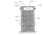
以下、従来のラック型電子機器の冷却装置について、図10を参照しながら説明する。 Hereinafter, a conventional cooling apparatus for rack-type electronic equipment will be described with reference to FIG.
図10に示すように、従来のラック型電子機器は、筐体101の内部に電子回路を構成する回路基板群102とヒートパイプ103、熱交換器104などで構成される冷却装置を備えている。回路基板群102は、筐体101内で、ラック型に整然と並べられている。そして、ヒートパイプ103は回路基板群102の隙間を縫うように設けられている。熱交換器104は、筐体101の上部に設けられていて、ヒートパイプ103が接続されている。筐体101の上部には、吸込口105、吹出口106となる開口が設けられ、吸込口105近傍に設けられた送風機107を動かすことによって外部の空気を通すようになっている。そして、吸込口105から吸い込まれた空気は、熱交換器104を通過した後、吹出口106から排出されるのである。
As shown in FIG. 10, a conventional rack-type electronic apparatus includes a cooling device including a
回路基板群102で発熱した熱は、周りの空気を暖め、この高温の空気はヒートパイプ103内の冷媒と熱交換して冷やされる。熱を受けた冷媒は蒸発してヒートパイプ103内を上昇し、熱交換器104内へと移動する。熱交換器104では、送風機107によって吸い込まれた冷たい外気と熱交換して再び液体となり、ヒートパイプ103内を下降していくのである。
The heat generated in the
このような従来の冷却装置では、ヒートパイプ103が回路基板群102の間を縫うように設けられているため、筐体101、回路基板群102を含んだ冷却装置全体として設計する必要があり、回路基板群102の大きさ、枚数ごとにヒートパイプ103の設計が必要になるという課題があった。
In such a conventional cooling device, since the
そして、図10に示す冷却装置では、ヒートパイプ103は、冷却装置全体で一つの冷却サイクルを構成しているため、回路ごとの発熱量の違いに対応することが困難であった。
In the cooling device shown in FIG. 10, since the
本発明はこのような課題を解決するものであり、電子機器と冷却装置を分離して設計することができ、個々の回路の発熱量に対応して適切に冷却できる冷却装置を提供することを目的としている。 The present invention solves such a problem, and can provide a cooling device that can be designed separately from an electronic device and a cooling device, and can be appropriately cooled according to the amount of heat generated by each circuit. It is aimed.
そして、この目的を達成するために本発明は、
筐体内に複数の電子回路基板を備えたラック型の電子機器を冷却する冷却装置において、
通風可能に開口を設け、内部に凝縮器と送風機を有し、前記筐体の天面に備えた箱形の凝縮器部と、内部に蒸発器を有し、前記筐体の背面側に設けた蒸発器部とを備え、前記凝縮器と前記蒸発器とを液管と蒸気管とで接続し、前記電子機器からの発熱は、前記蒸発器内の液状の冷媒を気化させて冷却し、前記電子機器外へ排出すると共に、前記凝縮器では、内部の気化した冷媒を外部から吸い込んだ冷たい空気で冷却して液化する冷凍サイクルを備えた冷却装置である。これにより所期の目的を達成するものである。
In order to achieve this object, the present invention
In a cooling device for cooling a rack-type electronic device having a plurality of electronic circuit boards in a housing,
An opening is provided to allow ventilation, a condenser and a blower are provided inside, a box-shaped condenser section provided on the top surface of the housing, and an evaporator inside, provided on the back side of the housing An evaporator unit, the condenser and the evaporator are connected by a liquid pipe and a vapor pipe, and heat generated from the electronic device is cooled by vaporizing a liquid refrigerant in the evaporator, The condenser is a cooling device provided with a refrigeration cycle that discharges outside the electronic apparatus and cools and liquefies the vaporized refrigerant in the condenser with cold air sucked from outside. This achieves the intended purpose.
本発明によれば、筐体内に複数の電子回路基板を備えたラック型の電子機器を冷却する冷却装置において、通風可能に開口を設け、内部に凝縮器と送風機を有し、前記筐体の天面に備えた箱形の凝縮器部と、内部に蒸発器を有し、前記筐体の背面側に設けた蒸発器部とを備え、前記凝縮器と前記蒸発器とを液管と蒸気管とで接続し、前記電子機器からの発熱は、前記蒸発器内の液状の冷媒を気化させて冷却し、前記電子機器外へ排出すると共に、前記凝縮器では、内部の気化した冷媒を外部から吸い込んだ冷たい空気で冷却して液化する冷凍サイクルを備えたことにより、内部の電子機器3の配置に関係なく、電子機器から排出される発熱を個別に処理することができる冷却装置を提供することができる。
According to the present invention, in a cooling device for cooling a rack-type electronic device having a plurality of electronic circuit boards in a housing, an opening is provided so as to allow ventilation, and a condenser and a blower are provided inside. A box-shaped condenser section provided on the top surface, an evaporator inside, and an evaporator section provided on the back side of the casing, the condenser and the evaporator being connected to a liquid tube and a vapor The heat generated from the electronic device is connected with a tube, and the liquid refrigerant in the evaporator is vaporized and cooled to be discharged to the outside of the electronic device. By providing a refrigeration cycle that cools and liquefies with cold air sucked from the inside, a cooling device that can individually process heat generated from the electronic device regardless of the arrangement of the internal
(実施の形態1)
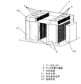
図1に示すのは、ラック型の電子機器(以降、ラック型電子機器2)を複数台納めたデータセンター1の概略図である。データセンター1内には、複数のラック型電子機器2が設置されている。ラック型電子機器2は、前面側と背面側に開口を設けた筐体を有し、その筐体内部にラック状に複数の電子機器3を、前面側に操作パネルや表示部を向けて備えられている。そして、背面側に電子機器3同士、あるいは、外部機器との接続を行う配線類、電源線類が設けられている。なお、全ての電子機器に操作パネルまたは表示部が備わっているとは限らない。このラック型電子機器2は、データセンター1内に複数台設置されて、全体として電子計算機室、サーバールームなどと呼ばれている。
(Embodiment 1)
FIG. 1 is a schematic diagram of a data center 1 in which a plurality of rack-type electronic devices (hereinafter, rack-type electronic devices 2) are accommodated. In the data center 1, a plurality of rack-type
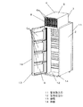
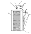
本実施の形態による冷却装置4は、図2に示すとおり、ラック型電子機器2の背面側を覆うように設けられた蒸発器部5と、ラック型電子機器2の上面に設けられた凝縮器部6とで構成されている。蒸発器部5には、平板状の蒸発器5aが複数枚取り付けられ、凝縮器部6内には、複数の平板状の凝縮器6aと外気送風機19が内蔵されている。また、凝縮器部6、蒸発器部5はともに内部を前後に空気が通過するように開口を有している。すなわち、凝縮器部6には外気吸込口7、外気吹出口8、蒸発器部5には排気吸込口9、排気吹出口10が設けられている。そして、蒸発器部5は、図3に示すように、ラック型電子機器2の筐体背面に、扉状に開閉可能に取り付けられている。
As shown in FIG. 2, the cooling device 4 according to the present embodiment includes an
一方、ラック型電子機器2は、前述のように前面と背面に空気の通過する開口を有している。この前面側の開口を空気取入口11、背面側の開口を空気吐出口12とする。これらの開口(空気取入口11、空気吐出口12)は、実質的に空気が通過する開口であればよく、空気取入口11は、パンチング、あるいは格子状、網状などの形態をとることが可能である。図3では、背面側の開口(空気吐出口12)は、扉状の蒸発器部5を開放したときに、背面略全体が一つの開口となっている。そして、筐体の内部には、複数の電子機器3が天井面(あるいは床面)と平行に並んでいる。なお、電子機器3は、側面に平行に並べてもよい。そして、ラック型電子機器2の内部を冷却するときには、空気取入口11から空気を吸い込んで、天井面(あるいは側面)に平行に並んだ電子機器3を通過するときに、電子機器3から発する熱を奪った後、空気吐出口12から排出されるのである。
On the other hand, as described above, the rack-type
次に蒸発器部5について説明する。
Next, the
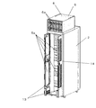
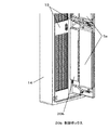
蒸発器部5は、周囲の枠と前面側から背面側へと空気が通り抜けられるように格子状のパネル部で構成された枠体内に、パネル部と平行に板状の蒸発器5aが設けられた扉部13と、この扉部13を軸支する枠部14とで構成されている。パネル部は、ラック型電子機器2の空気取入口11と同様、空気が通過する構成であれば、パンチング、あるいは、網状などのものでもよい。蒸発器5aは、ラック型電子機器2の筐体内を通過した空気が冷却されるよう、蒸発器部5全体に配置されている。本実施の形態では、4枚の蒸発器5aを上下に並べた構成である。
The
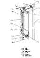
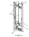
図4に示すように、蒸発器5aと凝縮器6aとを接続する配管14(液管15a、蒸気管15b)は、枠部14の内壁面に沿って縦に配置されている。液管15aは、蒸発器5aの下辺付近に端部を設けている。そして、蒸発器5a下辺に設けた液管接続口16と液管15aの端部とを曲げ自在のゴムホース17aで接続している。一方、蒸気管15bは、蒸発器5aの上辺よりも上側に端部を設け、蒸気管15bの端部と蒸発器5aの上辺に設けた蒸気管接続口18とをゴムホース17bで接続している。
As shown in FIG. 4, the pipe 14 (
このゴムホース17a、ゴムホース17bは、内面をIIR系ゴムとしたものや、内面をナイロン系樹脂にてコーティングした、例えば冷媒用ホースを用いるとよい。そして、ゴムホース17a、ゴムホース17bは、扉部13の回動軸近傍で略水平方向(回動軸に略直交する方向)になるように配置されている。また、ゴムホース17a、ゴムホース17bのそれぞれの両端における接続部分(液管15a、蒸発器5aとゴムホース17aとの接続部分および蒸気管15b、蒸発器5aとゴムホース17bとの接続部分)では、エルボを介してもよいし、ゴムホース17a、ゴムホース17bを曲げてもよい。この実施の形態では、ゴムホース17a、ゴムホース17bとしたが、曲げることができれば、ゴム以外の材質のチューブを用いることが可能である。例えば、金属製のフレキシブルホースなどのフレキシブル配管を適用することができる。
As the
次に凝縮器部6について説明する。
Next, the
凝縮器部6は、向かい合う面を通風可能に開口(外気吸込口7、外気吹出口8)した箱形の筐体内に、凝縮器6aと外気送風機19を納めたものである。外気吸込口7、外気吹出口8は、他の通気口同様、空気が通過する構成であれば、格子状、パンチング、あるいは、網状など様々な形態をとることができる。凝縮器6aは、外気送風機19が送り出す空気をあてて通過させるように配置する。図2においては、通風方向に対して斜めに傾けて配置している。また、凝縮器6aは、蒸発器5aの枚数と同数備え、一枚の蒸発器5aと一枚の凝縮器6aとを液管15a、蒸気管15bとで接続して一つのサーモサイフォン型冷媒サイクルを構成している。
The
前述したように、データセンター1内には複数のラック型電子機器2が設けられている。冷却装置4は、ラック型電子機器2に垂れかけるような形態で取り付けられている。すなわち、凝縮器部6をラック型電子機器2の天面に乗せ、蒸発器部5をラック型電子機器2の背面に取り付けられている。データセンター1は、ラック型電子機器2の天面を境にして、下部の本体空間51と上部の外気通風空間52とに仕切られている。本体空間51には、その内部の温度調節を行う空調装置53が設けられている。
As described above, a plurality of rack-type
上記構成において、ラック型電子機器2からの発熱の処理方法について説明する。
In the above configuration, a method for processing heat generated from the rack-type
まず、外気通風空間52において、凝縮器部6では、通過する外気によって凝縮器6a内の冷媒を冷却・凝縮させる。液化した冷媒は、蒸発器5aへと降下していく。一方、ラック型電子機器2内から発生する熱は、ラック型電子機器2内に設けられた排気送風機(図示せず)によって本体空間51内に排出される。そのとき、高温の排気空気は、蒸発器部5を通過するので、蒸発器5a内の冷媒を気化させて熱交換し、冷却される。さらに、本体空間51全体を空調装置53によって温度調節しているのである。
First, in the outside
従って、冷却装置4によってラック型電子機器2から排出される熱量を小さくするので、空調装置53の負荷が軽減され、データセンター1全体として、エネルギー消費の少ない温度制御が可能となる。また、ラック型電子機器2ごとに冷却装置4が設けられているので、各冷却装置4ごとに外気送風機19の送風量制御を行うことによって、ラック型電子機器2ごとの発熱量に対し、適切な冷却を行うことができる。
Accordingly, since the amount of heat discharged from the rack-type
前述したとおり、ラック型電子機器2の背面側には、内部の電子機器3同士、あるいは、外部機器との接続を行う配線類、電源線類が設けられている。蒸発器5aと凝縮器6aとの間の配管には、ゴムホース17a、ゴムホース17bが用いられているので、蒸発器部5は、扉状に開けることができる。従って、設置時の配線作業、あるいは、設置後のメンテナンスが容易に行えるようになっている。そして、ゴムホース17a、ゴムホース17bは、蒸発器部5の回動軸に直交するように設けられているので、ゴムホース17a、ゴムホース17bをねじることがなく、蒸発器部5は、少ない力で開閉動作を行うことができる。
As described above, on the back side of the rack-type
また、ラック型電子機器2内では発熱量の異なる電子機器3が納められている。そこで、冷却装置4内には、複数の冷媒サイクルを配置しているので、発熱量が異なっても冷却が可能なシステム構成となっている。
In the rack-type
なお、扉状の蒸発器部5は、図3に示すような片開きだけでなく、図5に示すような観音開き型でもよい。この場合には、ラック型電子機器2の背面側に必要なスペースを小さくすることができる。
In addition, the door-shaped
さらに、図6に示すような、蒸発器部5は、フラップ型に開閉するタイプでもよい。この場合、回動軸は水平方向になるので、蒸発器5aを接続するゴムホース17a、ゴムホース17bの回動軸近傍は、ほぼ鉛直方向になるように設ける。また、この場合には、蒸発器5aごとに開閉できるようにすることによって、背面側に必要なスペースを小さくすることができる。
Furthermore, the
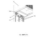
この冷却装置4においては、外気送風機19の運転制御を行う電子回路を備えた制御ボックス20が必要になる。その配置については、図7に記載のとおり、扉部13の下部に制御ボックス20aを備える。あるいは、図8に記載のとおり、制御ボックス20bを枠部14の内壁面に設けてもよい。さらには、凝縮器部6と蒸発器部5との間に制御ボックス20cを設けてもよい。それぞれの設置位置は、冷却装置4、あるいはラック型電子機器2のデッドスペースとなっているので、スペースの有効な利用が可能となる。さらに、それぞれ冷却装置4側に設けられているので、ラック型電子機器2の形態に影響を与えず、冷却装置4は、後付けが可能になる。
In the cooling device 4, a control box 20 including an electronic circuit that controls the operation of the
さらには、蒸発器5aの出口側の温度を検出し、制御ボックス20内の制御装置で外気送風機19の送風量制御を行うことにより、適切な温度制御が可能になる。
Furthermore, by detecting the temperature on the outlet side of the
本発明は、筐体内に複数の電子機器3を備えたラック型の電子機器を冷却する冷却装置において、
通風可能に開口を設け、内部に凝縮器と送風機を有し、前記筐体の天面に備えた箱形の凝縮器部と、
内部に蒸発器を有し、前記筐体の背面側に設けた蒸発器部とを備え、
前記凝縮器と前記蒸発器とを液管と蒸気管とで接続し、
前記電子機器からの発熱は、前記蒸発器内の液状の冷媒を気化させて冷却し、前記電子機器外へ排出すると共に、
前記凝縮器では、内部の気化した冷媒を外部から吸い込んだ冷たい空気で冷却して液化する冷凍サイクルを備えたことにより、内部の電子機器3の配置に関係なく、電子機器から排出される発熱を個別に処理することができるので、内部に電子機器を備えた屋内型の発熱体収納装置の冷却に利用可能である。
The present invention relates to a cooling device that cools a rack-type electronic device including a plurality of
A box-shaped condenser part provided on the top surface of the housing, having an opening for ventilation, having a condenser and a blower inside,
It has an evaporator inside, and comprises an evaporator section provided on the back side of the housing,
Connecting the condenser and the evaporator with a liquid pipe and a vapor pipe;
The heat generated from the electronic device is cooled by evaporating the liquid refrigerant in the evaporator, and discharged outside the electronic device.
The condenser is provided with a refrigeration cycle that cools and liquefies the vaporized refrigerant from the outside with cold air sucked from outside, so that heat generated from the
1 データセンター
2 ラック型電子機器
3 電子機器
4 冷却装置
5 蒸発器部
5a 蒸発器
6 凝縮器部
6a 凝縮器
7 外気吸込口
8 外気吹出口
9 排気吸込口
10 排気吹出口
11 空気取入口
12 空気吐出口
13 扉部
14 枠部
15a 液管
15b 蒸気管
16 液管接続口
17a ゴムホース
17b ゴムホース
18 蒸気管接続口
19 外気送風機
20 制御ボックス
20a 制御ボックス
20b 制御ボックス
20c 制御ボックス
51 本体空間
52 外気通風空間
53 空調装置
101 筐体
102 回路基板群
103 ヒートパイプ
104 熱交換器
105 吸込口
106 吹出口
107 送風機
DESCRIPTION OF SYMBOLS 1
Claims (10)
通風可能に開口を設け、内部に凝縮器と送風機を有し、前記筐体の天面に備えた箱形の凝縮器部と、
内部に蒸発器を有し、前記筐体の背面側に設けた蒸発器部とを備え、
前記凝縮器と前記蒸発器とを液管と蒸気管とで接続し、
前記電子機器からの発熱は、前記蒸発器内の液状の冷媒を気化させて冷却し、前記電子機器外へ排出すると共に、
前記凝縮器では、内部の気化した冷媒を外部から吸い込んだ冷たい空気で冷却して液化する冷凍サイクルを備えた冷却装置。 In a cooling device for cooling a rack-type electronic device having a plurality of electronic devices in a housing,
A box-shaped condenser part provided on the top surface of the housing, having an opening for ventilation, having a condenser and a blower inside,
It has an evaporator inside, and comprises an evaporator section provided on the back side of the housing,
Connecting the condenser and the evaporator with a liquid pipe and a vapor pipe;
The heat generated from the electronic device is cooled by evaporating the liquid refrigerant in the evaporator, and discharged outside the electronic device.
In the condenser, a cooling device provided with a refrigeration cycle that cools and liquefies the vaporized refrigerant inside with cold air sucked from outside.
前記蒸発器の扉状に開閉する回動軸と直交するように曲げ自在のフレキシブル配管で接続した請求項2〜5いずれか一つに記載の冷却装置。 In the connection between the evaporator and the steam pipe,
The cooling device according to any one of claims 2 to 5, wherein the cooling device is connected by a flexible pipe that can be bent so as to be orthogonal to a rotation axis that opens and closes in a door shape of the evaporator.
このデータセンター内を上部の外気通風空間と下部の本体空間に分離し、
前記電子機器は、前記本体空間に配置し、
それぞれの電子機器に請求項1〜9いずれか一つに記載の冷却装置を備え、
前記凝縮器を前記外気通風空間内に備えたデータセンター。 In a data center where a plurality of the rack-type electronic devices are arranged,
The inside of this data center is separated into the upper outside air ventilation space and the lower body space,
The electronic device is disposed in the main body space,
Each electronic device includes the cooling device according to any one of claims 1 to 9,
A data center including the condenser in the outside air ventilation space.
Priority Applications (5)
| Application Number | Priority Date | Filing Date | Title |
|---|---|---|---|
| JP2011051220A JP2012190884A (en) | 2011-03-09 | 2011-03-09 | Cooling device of rack type electronic apparatus |
| PCT/JP2012/001341 WO2012120830A1 (en) | 2011-03-09 | 2012-02-28 | Cooling device for rack-type electronic equipment and data centre |
| CN2012800121823A CN103430644A (en) | 2011-03-09 | 2012-02-28 | Cooling device for rack-type electronic equipment and data centre |
| US13/983,772 US9192074B2 (en) | 2011-03-09 | 2012-02-28 | Cooling device for rack-type electronic equipment and data centre |
| TW101107311A TWI474772B (en) | 2011-03-09 | 2012-03-05 | Cooling equipment and data center for rack-mounted electronic equipment |
Applications Claiming Priority (1)
| Application Number | Priority Date | Filing Date | Title |
|---|---|---|---|
| JP2011051220A JP2012190884A (en) | 2011-03-09 | 2011-03-09 | Cooling device of rack type electronic apparatus |
Publications (1)
| Publication Number | Publication Date |
|---|---|
| JP2012190884A true JP2012190884A (en) | 2012-10-04 |
Family
ID=46797805
Family Applications (1)
| Application Number | Title | Priority Date | Filing Date |
|---|---|---|---|
| JP2011051220A Withdrawn JP2012190884A (en) | 2011-03-09 | 2011-03-09 | Cooling device of rack type electronic apparatus |
Country Status (5)
| Country | Link |
|---|---|
| US (1) | US9192074B2 (en) |
| JP (1) | JP2012190884A (en) |
| CN (1) | CN103430644A (en) |
| TW (1) | TWI474772B (en) |
| WO (1) | WO2012120830A1 (en) |
Cited By (3)
| Publication number | Priority date | Publication date | Assignee | Title |
|---|---|---|---|---|
| JP2016024539A (en) * | 2014-07-17 | 2016-02-08 | 篠原電機株式会社 | Air conditioning device for server system |
| JP5873155B1 (en) * | 2014-10-17 | 2016-03-01 | Necプラットフォームズ株式会社 | Monitoring system, monitoring apparatus and monitoring method |
| JPWO2014132592A1 (en) * | 2013-02-26 | 2017-02-02 | 日本電気株式会社 | Electronic device cooling system and method of manufacturing electronic device cooling system |
Families Citing this family (14)
| Publication number | Priority date | Publication date | Assignee | Title |
|---|---|---|---|---|
| JP5775062B2 (en) | 2012-12-27 | 2015-09-09 | レノボ・シンガポール・プライベート・リミテッド | Electronic equipment and electronic equipment system |
| US9648784B2 (en) * | 2013-03-15 | 2017-05-09 | Inertech Ip Llc | Systems and assemblies for cooling server racks |
| US20140293541A1 (en) * | 2013-03-26 | 2014-10-02 | Ge Energy Power Conversion Technology Ltd | Heat pipe heat sink for high power density |
| JP5469773B1 (en) * | 2013-07-16 | 2014-04-16 | 新日鉄住金エンジニアリング株式会社 | Server rack indoor system |
| CN103596411B (en) * | 2013-11-29 | 2015-12-30 | 北京普拉斯科技发展有限公司 | Modularized combinable heat pipe cabinet |
| US9357681B2 (en) * | 2014-05-22 | 2016-05-31 | Amazon Technologies, Inc. | Modular data center row infrastructure |
| US9559517B2 (en) | 2014-09-16 | 2017-01-31 | Hoffman Enclosures, Inc. | Encapsulation of components and a low energy circuit for hazardous locations |
| US10448543B2 (en) * | 2015-05-04 | 2019-10-15 | Google Llc | Cooling electronic devices in a data center |
| CN104866040A (en) * | 2015-06-12 | 2015-08-26 | 苏州圣谱拉新材料科技有限公司 | Novel water-screen radiating computer case |
| US10462935B2 (en) | 2015-06-23 | 2019-10-29 | Google Llc | Cooling electronic devices in a data center |
| US10206312B2 (en) | 2015-12-21 | 2019-02-12 | Dell Products, L.P. | Liquid cooled rack information handling system having storage drive carrier for leak containment and vibration mitigation |
| CN109661138B (en) * | 2019-01-23 | 2020-10-23 | 安徽航睿电子科技有限公司 | Power communication network equipment box |
| PL3703477T3 (en) * | 2019-02-28 | 2022-02-14 | Ovh | Heat extraction system for a computing equipment enclosure |
| US12063762B2 (en) * | 2021-02-24 | 2024-08-13 | Dynamic Data Centers Solutions, Inc. | Cooling servers with hybrid water to air and heat pipe augmentation to chip level cooling outside of server |
Family Cites Families (27)
| Publication number | Priority date | Publication date | Assignee | Title |
|---|---|---|---|---|
| JPS57195897U (en) | 1981-06-05 | 1982-12-11 | ||
| JPS6271299A (en) | 1985-09-25 | 1987-04-01 | 日本電信電話株式会社 | Cooling structure for electronic device |
| JPH0497396U (en) | 1991-01-21 | 1992-08-24 | ||
| US6536510B2 (en) * | 2001-07-10 | 2003-03-25 | Thermal Corp. | Thermal bus for cabinets housing high power electronics equipment |
| US6834713B2 (en) * | 2002-07-18 | 2004-12-28 | Delphi Technologies, Inc. | Thermosiphon for electronics cooling with nonuniform airflow |
| US7013955B2 (en) * | 2003-07-28 | 2006-03-21 | Thermal Corp. | Flexible loop thermosyphon |
| US7958935B2 (en) * | 2004-03-31 | 2011-06-14 | Belits Computer Systems, Inc. | Low-profile thermosyphon-based cooling system for computers and other electronic devices |
| US7365973B2 (en) * | 2006-01-19 | 2008-04-29 | American Power Conversion Corporation | Cooling system and method |
| US20070297136A1 (en) * | 2006-06-23 | 2007-12-27 | Sun Micosystems, Inc. | Modular liquid cooling of electronic components while preserving data center integrity |
| WO2008011458A1 (en) * | 2006-07-18 | 2008-01-24 | Liebert Corporation | Integral swivel hydraulic connectors, door hinges, and methods and systems for the use thereof |
| US9060451B2 (en) * | 2007-02-26 | 2015-06-16 | Google Inc. | Targeted cooling for datacenters |
| GB0703995D0 (en) * | 2007-03-01 | 2007-04-11 | Stevens Jason | Data centers |
| US7963118B2 (en) * | 2007-09-25 | 2011-06-21 | International Business Machines Corporation | Vapor-compression heat exchange system with evaporator coil mounted to outlet door of an electronics rack |
| JP2009135287A (en) | 2007-11-30 | 2009-06-18 | Sanyo Electric Co Ltd | Electronic apparatus cooling device |
| US7660109B2 (en) * | 2007-12-17 | 2010-02-09 | International Business Machines Corporation | Apparatus and method for facilitating cooling of an electronics system |
| US7791882B2 (en) * | 2008-04-23 | 2010-09-07 | International Business Machines Corporation | Energy efficient apparatus and method for cooling an electronics rack |
| EP2117288A1 (en) | 2008-05-07 | 2009-11-11 | 3M Innovative Properties Company | Heat-management system for a cabinet containing electronic equipment |
| US20100096105A1 (en) * | 2008-10-20 | 2010-04-22 | Vette Corp. | Rear door heat exchanger transition frame |
| US8184435B2 (en) * | 2009-01-28 | 2012-05-22 | American Power Conversion Corporation | Hot aisle containment cooling system and method |
| US8369090B2 (en) * | 2009-05-12 | 2013-02-05 | Iceotope Limited | Cooled electronic system |
| US8035972B2 (en) * | 2009-07-31 | 2011-10-11 | Oracle America, Inc. | Method and apparatus for liquid cooling computer equipment |
| US8120916B2 (en) * | 2009-09-17 | 2012-02-21 | International Business Machines Corporation | Facilitating cooling of an electronics rack employing water vapor compression system |
| US8789384B2 (en) * | 2010-03-23 | 2014-07-29 | International Business Machines Corporation | Computer rack cooling using independently-controlled flow of coolants through a dual-section heat exchanger |
| US8351206B2 (en) * | 2010-06-29 | 2013-01-08 | International Business Machines Corporation | Liquid-cooled electronics rack with immersion-cooled electronic subsystems and vertically-mounted, vapor-condensing unit |
| US8274790B2 (en) * | 2010-11-16 | 2012-09-25 | International Business Machines Corporation | Automatically reconfigurable liquid-cooling apparatus for an electronics rack |
| US8488323B2 (en) * | 2010-12-03 | 2013-07-16 | Microsoft Corporation | Controlling minimum air inlet temperature using waste heat |
| US9007221B2 (en) * | 2013-08-16 | 2015-04-14 | Cisco Technology, Inc. | Liquid cooling of rack-mounted electronic equipment |
-
2011
- 2011-03-09 JP JP2011051220A patent/JP2012190884A/en not_active Withdrawn
-
2012
- 2012-02-28 WO PCT/JP2012/001341 patent/WO2012120830A1/en not_active Ceased
- 2012-02-28 US US13/983,772 patent/US9192074B2/en active Active
- 2012-02-28 CN CN2012800121823A patent/CN103430644A/en active Pending
- 2012-03-05 TW TW101107311A patent/TWI474772B/en not_active IP Right Cessation
Cited By (3)
| Publication number | Priority date | Publication date | Assignee | Title |
|---|---|---|---|---|
| JPWO2014132592A1 (en) * | 2013-02-26 | 2017-02-02 | 日本電気株式会社 | Electronic device cooling system and method of manufacturing electronic device cooling system |
| JP2016024539A (en) * | 2014-07-17 | 2016-02-08 | 篠原電機株式会社 | Air conditioning device for server system |
| JP5873155B1 (en) * | 2014-10-17 | 2016-03-01 | Necプラットフォームズ株式会社 | Monitoring system, monitoring apparatus and monitoring method |
Also Published As
| Publication number | Publication date |
|---|---|
| US9192074B2 (en) | 2015-11-17 |
| US20130314873A1 (en) | 2013-11-28 |
| CN103430644A (en) | 2013-12-04 |
| TWI474772B (en) | 2015-02-21 |
| WO2012120830A1 (en) | 2012-09-13 |
| TW201242504A (en) | 2012-10-16 |
Similar Documents
| Publication | Publication Date | Title |
|---|---|---|
| JP2012190884A (en) | Cooling device of rack type electronic apparatus | |
| US10292313B2 (en) | Rackmount cooling system | |
| US9317080B2 (en) | Local cooling unit and cooling system | |
| CN207230813U (en) | A kind of integrated air conditioner and cabinet | |
| WO2007108447A1 (en) | Outdoor unit of air conditioner | |
| CN101668996B (en) | Air conditioner | |
| JP6649098B2 (en) | Exhaust cooling device and exhaust cooling method of refrigerant natural circulation type | |
| JP2014092322A (en) | Cooling device and server device mounting the same | |
| CN216693786U (en) | Air conditioning system and container | |
| JP5247132B2 (en) | Air conditioning system | |
| JP2009134531A (en) | Electronic device cooling system | |
| CN103857262B (en) | Container type data center heat dissipation system | |
| JP2004232927A (en) | Rack for storing electronic equipment, air conditioner for computer room, and air conditioner system for computer room | |
| JP2013200762A (en) | Cooling device of rack type electronic device | |
| WO2017097029A1 (en) | Internal air conditioner indoor unit applicable to 19-inch standard cabinet | |
| JP2009135287A (en) | Electronic apparatus cooling device | |
| JP7304640B2 (en) | Computer rack equipment that utilizes the cooling part | |
| CN216346635U (en) | Indoor unit of air conditioner | |
| CN205957446U (en) | Service gate -type fan coil for rack | |
| CN213630744U (en) | Integrated Server Rack Air Conditioner | |
| JP5386735B2 (en) | Cooling system | |
| CN203869189U (en) | Outdoor unit and air conditioning device | |
| JP2012142026A (en) | Cooling system for electronic apparatus | |
| JP4560967B2 (en) | Air conditioner | |
| CN223515201U (en) | Cabinet air conditioner |
Legal Events
| Date | Code | Title | Description |
|---|---|---|---|
| A300 | Application deemed to be withdrawn because no request for examination was validly filed |
Free format text: JAPANESE INTERMEDIATE CODE: A300 Effective date: 20140513 |