JP2012190582A - Lighting unit, lighting device, and display device - Google Patents

Lighting unit, lighting device, and display device Download PDF

Info

Publication number
JP2012190582A
JP2012190582A JP2011051253A JP2011051253A JP2012190582A JP 2012190582 A JP2012190582 A JP 2012190582A JP 2011051253 A JP2011051253 A JP 2011051253A JP 2011051253 A JP2011051253 A JP 2011051253A JP 2012190582 A JP2012190582 A JP 2012190582A
Authority
JP
Japan
Prior art keywords
light
diffusion
region
sheet
guide plate
Prior art date
Legal status (The legal status is an assumption and is not a legal conclusion. Google has not performed a legal analysis and makes no representation as to the accuracy of the status listed.)
Withdrawn
Application number
JP2011051253A
Other languages
Japanese (ja)
Inventor
Masaru Okubo
優 大久保
Current Assignee (The listed assignees may be inaccurate. Google has not performed a legal analysis and makes no representation or warranty as to the accuracy of the list.)
Toppan Inc
Original Assignee
Toppan Printing Co Ltd
Priority date (The priority date is an assumption and is not a legal conclusion. Google has not performed a legal analysis and makes no representation as to the accuracy of the date listed.)
Filing date
Publication date
Application filed by Toppan Printing Co Ltd filed Critical Toppan Printing Co Ltd
Priority to JP2011051253A priority Critical patent/JP2012190582A/en
Publication of JP2012190582A publication Critical patent/JP2012190582A/en
Withdrawn legal-status Critical Current

Links

Images

Abstract

PROBLEM TO BE SOLVED: To provide a lighting unit that improves front luminance while optical deflection elements of a light guide plate are made hardly visible.SOLUTION: In the lighting unit 7 including a surface light source device 2 having a light source 11, the light guide plate 10 with an incident end surface, an emitting surface, and an optical deflection surface, and a reflection sheet 9, a diffusion sheet 3, and a diffusion and condensing sheet 4 for coping with both of diffusion of light and improvement of luminance, the optical deflection elements 13 provided on an optical deflection surface 12 are extended in a first direction in parallel with the end surface, and are arranged in one-dimensional array arranged in a second direction perpendicular to the end surface. The light guide plate 10 is divided into two zones such as the zone A wherein an arrangement pitch of the optical deflection elements is 500 μm or more and the zone B wherein the arrangement pitch of the optical deflection elements is less than 500 μm. The diffusion and condensing sheet 4 diffuses light emitted from the zone A in one-dimensional direction or two-dimensional direction at an angular distribution wider than the light emitted from the zone B.

Description

本発明は、主に照明光路制御に使用される拡散集光シートを備えた照明ユニット、照明装置並びに表示装置に関するものである。   The present invention relates to an illuminating unit, an illuminating device, and a display device that include a diffusing and condensing sheet mainly used for illuminating optical path control.

最近の大型液晶テレビやフラットパネルディスプレイ等においては、主に、直下型方式の照明装置と、エッジライト方式の照明装置とが採用されている。直下型方式の照明装置は、光源として複数の冷陰極管やLED(Light Emitting Diode)が、パネルの背面に規則的に配置される。液晶パネル等の画像表示素子と光源との間には、光散乱性の強い拡散板が用いられ、光源としての冷陰極管やLEDが視認されないようにしている。   In recent large-sized liquid crystal televisions, flat panel displays, etc., direct type illumination devices and edge light illumination devices are mainly employed. In the direct type illumination device, a plurality of cold cathode tubes and LEDs (Light Emitting Diodes) are regularly arranged as light sources on the back surface of the panel. A light diffusing plate is used between the image display element such as a liquid crystal panel and the light source so that a cold cathode tube or LED as a light source is not visually recognized.

一方、エッジライト方式の照明装置は、複数の冷陰極管やLED等の光源が、導光板と呼ばれる透光性の板の端面に配置される。一般的に、導光板の射出面(画像表示素子と対向する面)の逆側の面には、該導光板の端面から入射する入射光を効率良く射出面へと導く光偏向面が形成され、光偏向面に形成される光偏向要素としては例えば白色のドットパターンが印刷されたもの、あるいは、レンズ形状が付与されたもの等、効率よく射出面へと導くために様々な光偏向要素が提案されている。   On the other hand, in an edge light type lighting device, a plurality of light sources such as cold cathode tubes and LEDs are arranged on an end face of a light-transmitting plate called a light guide plate. In general, a light deflection surface that efficiently guides incident light incident from the end surface of the light guide plate to the exit surface is formed on the surface opposite to the exit surface of the light guide plate (the surface facing the image display element). The light deflecting elements formed on the light deflecting surface include various light deflecting elements for efficiently leading to the exit surface, such as those printed with a white dot pattern or those provided with a lens shape. Proposed.

しかしながら、エッジライト方式は、導光板と呼ばれる透光性の板の端面にのみ光源が配置される構造のため、光源設置数に限界がある。従って液晶表示装置が大型になるにつれ、ディスプレイ全体を明るくすることは難しくなり、輝度を向上させる光学シートの役割が重要となる。   However, since the edge light system has a structure in which the light source is disposed only on the end face of a light-transmitting plate called a light guide plate, the number of light sources installed is limited. Therefore, as the liquid crystal display device becomes larger, it becomes difficult to brighten the entire display, and the role of the optical sheet for improving the brightness becomes important.

液晶表示画面の輝度を向上させる手段として、米国3M社(ミネソタ マイニング アンド マニュファクチャリング カンパニー)の登録商標であるBEF(Brightness Enhancement Films:輝度向上フィルム)がレンズシートとして広く使用されている。
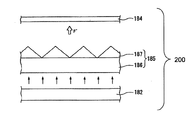
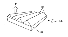
図7、図8は下記特許文献1、2に説明されている輝度向上フィルムを示す図面であり、図7は、BEFを用いた従来の液晶表示装置の構成を説明するための模式断面図である。概略で、面光源182と、面光源182から出射した矢印で示す光を入射させる輝度向上フィルムとしてのBEF185と、液晶パネル184とが配設されている。図8は、図7に示すBEF185の斜視図であって、BEF185は、透明基材186上に断面が三角形状の複数のプリズム187が一方向に周期的に配列されてなる光学フィルムである。このプリズム187の単位幅は光の波長に比較して大きいサイズであり、配列ピッチは光の波長に比較して大きくなるように構成され、ブロック矢印F’に示す方向に集光した光を射出することができる。
As means for improving the brightness of a liquid crystal display screen, BEF (Brightness Enhancement Films), which is a registered trademark of 3M Corporation (Minnesota Mining and Manufacturing Company), is widely used as a lens sheet.
7 and 8 are diagrams showing brightness enhancement films described in Patent Documents 1 and 2 below, and FIG. 7 is a schematic cross-sectional view for explaining the configuration of a conventional liquid crystal display device using BEF. is there. Schematically, a surface light source 182, a BEF 185 as a brightness enhancement film on which light indicated by an arrow emitted from the surface light source 182 is incident, and a liquid crystal panel 184 are disposed. FIG. 8 is a perspective view of the BEF 185 shown in FIG. 7, and the BEF 185 is an optical film in which a plurality of prisms 187 having a triangular cross section are periodically arranged in one direction on a transparent substrate 186. The unit width of the prism 187 is larger than the wavelength of the light, and the arrangement pitch is larger than the wavelength of the light. The condensed light is emitted in the direction indicated by the block arrow F ′. can do.

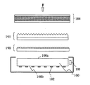
また、図6は、従来技術によるBEFを含む液晶表示装置の配置構成を、光源101を導光板100の端面に配置したエッジライト方式の照明装置を用いた例について示す要部断面図である。例えばBEFを用いたレンズシート191は、“軸外(off-axis)”からの光を集光し、この光を観察者に向けて“軸上(on-axis)”に方向転換(redirect)または“リサイクル(recycle)”させることができる。すなわちBEFは、液晶表示装置の使用時(観察時)に、軸外輝度を低下させることによって軸上輝度を増大させることができる。ここで言う「軸上」とは、図6において観察者の視覚方向Fに一致する方向であり、一般的には液晶パネル184の表示画面に対する法線方向である。   FIG. 6 is a cross-sectional view of an essential part showing an arrangement configuration of a liquid crystal display device including a BEF according to a conventional technique using an edge light type illumination device in which a light source 101 is arranged on an end face of a light guide plate 100. For example, a lens sheet 191 using BEF collects light from “off-axis” and redirects this light “on-axis” toward the viewer. Or it can be “recycled”. That is, BEF can increase the on-axis brightness by reducing the off-axis brightness when using the liquid crystal display device (when observing). Here, “on-axis” is a direction that coincides with the visual direction F of the observer in FIG. 6, and is generally a normal direction to the display screen of the liquid crystal panel 184.

ところで、エッジライト方式において使用される導光板100は、上述したとおり、射出面100aと対向する位置に光偏向面100bを備え、光偏向面100bには白色のドットパターンやマイクロレンズ(凹型、凸型)、その他レンズ形状の光偏向要素102が形成される。光偏向要素102として、或いは、一次元方向、もしくは二次元方向に配列された溝、もしくは突起による微小反射要素を形成し、これら微小反射要素の全反射によって光射出面側へ光を反射させて視覚方向F側へ光を射出させる構成など、輝度向上に関わる様々なバリエーションの導光板100が提案されている。   Incidentally, as described above, the light guide plate 100 used in the edge light system includes the light deflection surface 100b at a position facing the exit surface 100a, and the light deflection surface 100b has a white dot pattern or a microlens (concave, convex). Mold) and other lens-shaped light deflection elements 102 are formed. As the light deflecting element 102, a minute reflecting element is formed by grooves or protrusions arranged in a one-dimensional direction or two-dimensional direction, and light is reflected toward the light exit surface side by total reflection of these minute reflecting elements. Various variations of the light guide plate 100 related to luminance improvement have been proposed, such as a configuration in which light is emitted toward the visual direction F side.

しかしながら、どのような光偏向要素102であっても、規則的に、または規則性を有しながら擬似不規則的に配列された反射層や構造物で形成されるため、上述のように規則性を有する構造のBEFに代表されるレンズシート191との間で、干渉によるモアレ干渉縞の問題や、光偏向面100bのムラが視認されるといった問題がある。その解決手段として、導光板100とレンズシート191との間に、特許文献3に示されるような拡散シート190を使用する方法が一般的である。   However, since any light deflection element 102 is formed of a reflective layer or a structure that is regularly or quasi- irregularly arranged with regularity, the regularity as described above. There is a problem of moire interference fringes due to interference and unevenness of the light deflection surface 100b with a lens sheet 191 represented by a BEF having a structure having the above. As a solution, a method of using a diffusion sheet 190 as shown in Patent Document 3 between the light guide plate 100 and the lens sheet 191 is common.

拡散シート190は、透明基材上に拡散フィラーが塗布された拡散フィルムを用いて、BEFに代表されるレンズシート191を用いる際に、導光板100とレンズシート191との間に配置することによって、導光板100の射出面100aから出射される光の輝度ムラを抑えてレンズシート191の平面上に均一な光を入射することができる。   The diffusion sheet 190 is disposed between the light guide plate 100 and the lens sheet 191 when a lens sheet 191 represented by BEF is used using a diffusion film in which a diffusion filler is applied on a transparent substrate. In addition, it is possible to make uniform light incident on the plane of the lens sheet 191 while suppressing luminance unevenness of the light emitted from the exit surface 100 a of the light guide plate 100.

しかしながら、特に、光偏向要素102が一次元方向に配列された溝、もしくは突起であって、それらのピッチが大きい場合には、上記のように拡散シート190を使用して光の平面均一化を図った場合であっても、視覚方向F側で光偏向要素102が視認されてしまうことがある。すなわち、光偏向要素が視認されず、しかも高い輝度が得られる照明ユニットが容易に得られなかった。   However, in particular, when the light deflecting elements 102 are grooves or protrusions arranged in a one-dimensional direction and their pitch is large, the light plane is uniformized using the diffusion sheet 190 as described above. Even in the illustrated case, the light deflection element 102 may be visually recognized on the visual direction F side. That is, an illumination unit in which the light deflection element is not visually recognized and high brightness is obtained cannot be easily obtained.

特公平1−37801号公報Japanese Patent Publication No. 1-378001 特開平6−102506号公報JP-A-6-102506 特開2004−295080号公報JP 2004-295080 A

本発明は、前記の問題点に鑑みて提案するものであり、本発明が解決しようとする課題は、導光板の光偏向面に形成される光偏向要素を視覚方向から隠蔽すると共に正面輝度を向上させることのできる照明ユニットおよび照明装置ならびにこの照明装置を用いた表示装置を提供することである。   The present invention is proposed in view of the above problems, and the problem to be solved by the present invention is to conceal the light deflection element formed on the light deflection surface of the light guide plate from the visual direction and to increase the front luminance. It is an object to provide an illumination unit and an illumination device that can be improved, and a display device using the illumination device.

上記の課題を解決するための手段として、請求項1に記載の発明は、光源と、光源から射出される光を入射する端面と入射した光を観察側へと射出する射出面と入射した光を射出面へと導く光偏向面とを備えた導光板と、射出面を除く導光板の面から射出する光を反射して導光板へと導く反射シートと、を備えた面光源装置と、面光源装置の射出面側に設けて入射した光を二次元方向に拡散する拡散シートと、拡散シートの観察側に設けて光の拡散と輝度向上とを両立させる拡散集光シートと、からなる照明ユニットであって、導光板は、光偏向面に、該導光板に入射された光を射出面側へと導く光偏向要素を備え、光偏向要素は、端面と平行な第一の方向に延在し、端面と垂直な第二の方向に配列してなる一次元配列で配置され、導光板は、光偏向要素の配列ピッチが500μm以上の領域Aと5
00μm未満の領域Bの2つの領域に分けられ、拡散集光シートは、領域Aから射出した光を、領域Bから射出した光よりも広い角度分布で、一次元方向、もしくは二次元方向に拡散することを特徴とする照明ユニットである。
As means for solving the above-mentioned problems, the invention according to claim 1 is directed to a light source, an end face on which light emitted from the light source is incident, an emission surface on which incident light is emitted to the observation side, and incident light. A surface light source device comprising: a light guide plate provided with a light deflection surface that guides the light to the exit surface; and a reflection sheet that reflects light emitted from the surface of the light guide plate excluding the exit surface to guide the light guide plate; A diffusion sheet that is provided on the exit surface side of the surface light source device and diffuses incident light in a two-dimensional direction, and a diffusion condensing sheet that is provided on the observation side of the diffusion sheet to achieve both diffusion of light and improvement in luminance. In the illumination unit, the light guide plate includes, on the light deflection surface, a light deflection element that guides light incident on the light guide plate to the exit surface side, and the light deflection element is in a first direction parallel to the end surface. It is arranged in a one-dimensional arrangement that extends and is arranged in a second direction perpendicular to the end face. The arrangement pitch of the light deflection elements and more areas A 500 [mu] m 5
Divided into two areas of area B less than 00 μm, the diffusion condensing sheet diffuses the light emitted from area A in a one-dimensional direction or two-dimensional direction with a wider angular distribution than the light emitted from area B It is the lighting unit characterized by doing.

本発明による拡散集光シートを備えた照明ユニットによれば、観察側から照明ユニットを目視した際に、導光板の光偏向面に形成される光偏向要素の像が拡散されることにより、光偏向要素の像が視認できないため照明ムラが少なく、しかも正面輝度を向上させることができる。   According to the illumination unit including the diffusion condensing sheet according to the present invention, when the illumination unit is viewed from the observation side, an image of the light deflection element formed on the light deflection surface of the light guide plate is diffused. Since the image of the deflection element cannot be visually recognized, there is little illumination unevenness and the front luminance can be improved.

また、請求項2に記載の発明は、拡散集光シートの観察側に面した光射出面の内、領域Aに対向する領域には、円柱状の曲面により形成された複数のレンズが第一の方向に延在するように配列され、拡散集光シートの観察側に面した光射出面の内、領域Bに対向する領域には、断面が三角形状の複数のプリズムが第一の方向に延在するように配列されることを特徴とする請求項1に記載の照明ユニットである。   Further, in the invention according to claim 2, a plurality of lenses formed by cylindrical curved surfaces are first in a region facing the region A in the light exit surface facing the observation side of the diffusion condensing sheet. A plurality of prisms having a triangular cross section are arranged in a first direction in a region facing the region B out of the light exit surface facing the observation side of the diffusion condensing sheet. The lighting unit according to claim 1, wherein the lighting unit is arranged to extend.

また、請求項3に記載の発明は、拡散集光シートの観察側に面した光射出面に、断面が三角形状の複数のプリズムが第一の方向に延在するように配列され、領域Aに対向する拡散集光シートの領域に配列される複数のプリズムの表面には光拡散層が形成されていることを特徴とする請求項1に記載の照明ユニットである。   The invention according to claim 3 is arranged such that a plurality of prisms having a triangular cross section extend in the first direction on the light exit surface facing the observation side of the diffusion condensing sheet, and the region A 2. The illumination unit according to claim 1, wherein a light diffusion layer is formed on the surfaces of the plurality of prisms arranged in the region of the diffusion condensing sheet opposed to the light.

また、請求項4に記載の発明は、拡散集光シートの観察側に面した光射出面に、円柱状の曲面により形成された複数のレンズが第一の方向に延在するように配列され、領域Aに対向する拡散集光シートの領域に配列される複数のレンズの表面には光拡散層が形成されていることを特徴とする請求項1に記載の照明ユニットである。   In the invention according to claim 4, a plurality of lenses formed by cylindrical curved surfaces are arranged on the light exit surface facing the observation side of the diffusion condensing sheet so as to extend in the first direction. 2. The illumination unit according to claim 1, wherein a light diffusion layer is formed on surfaces of a plurality of lenses arranged in a region of the diffusion condensing sheet facing the region A. 3.

また、請求項5に記載の発明は、拡散集光シートの拡散シート側に面した光入射面の内、領域Aに対向する領域に、粗面が形成されていることを特徴とする請求項1に記載の照明ユニットである。   The invention according to claim 5 is characterized in that a rough surface is formed in a region facing the region A in the light incident surface facing the diffusion sheet side of the diffusion condensing sheet. The lighting unit according to 1.

また、請求項6に記載の発明は、拡散集光シートの拡散シート側に面した光入射面の内、領域Aに対向する領域に、第二の方向に光を拡散する指向性拡散層が形成されていることを特徴とする請求項1に記載の照明ユニットである。   In the invention according to claim 6, a directional diffusion layer for diffusing light in the second direction is provided in a region facing the region A in the light incident surface facing the diffusion sheet side of the diffusion condensing sheet. The lighting unit according to claim 1, wherein the lighting unit is formed.

また、請求項7に記載の発明は、請求項1〜6のいずれかに記載の照明ユニットに、該照明ユニットから出射した光を偏光させる反射型偏光分離シートを備えたことを特徴とする照明装置である。   The invention according to claim 7 is an illumination characterized in that the illumination unit according to any one of claims 1 to 6 is provided with a reflective polarization separation sheet that polarizes light emitted from the illumination unit. Device.

本発明による照明装置によれば、反射型偏光分離シートを有することにより、照明ユニットから出射した光の内、特定の偏光成分を選択的に透過させ、他の偏光成分を反射させることができるので、液晶表示装置用の照明装置として、上記本発明の照明ユニットによる照明ムラの減少とともに、輝度を効率良く高めることができる。   According to the illuminating device of the present invention, by including the reflective polarization separation sheet, it is possible to selectively transmit a specific polarization component and reflect other polarization components in the light emitted from the illumination unit. As a lighting device for a liquid crystal display device, it is possible to efficiently increase luminance along with the reduction of uneven illumination by the lighting unit of the present invention.

また、請求項8に記載の発明は、請求項1〜6に記載の照明ユニットまたは請求項7に記載の照明装置のいずれかを、表示画像を規定する画像表示素子に備えたことを特徴とする表示装置である。   The invention described in claim 8 is characterized in that any one of the illumination unit according to claims 1 to 6 or the illumination device according to claim 7 is provided in an image display element that defines a display image. Display device.

本発明による表示装置によれば、観察側から目視した際に、面光源装置から出射した光を、拡散集光シートによって導光板の光偏向面に形成される光偏向要素を視認できないように隠蔽してムラのない画面を表示するとともに、正面輝度が向上した明るい表示装置を提供することができる。   According to the display device of the present invention, when viewed from the observation side, the light emitted from the surface light source device is concealed so that the light deflection element formed on the light deflection surface of the light guide plate cannot be visually recognized by the diffusion condensing sheet. Thus, it is possible to provide a bright display device that displays a non-uniform screen and has improved front luminance.

本発明による拡散集光シートを備えた照明ユニットによれば、観察側から照明ユニットを目視した際に、導光板の光偏向面に形成される光偏向要素の像が拡散されることにより、光偏向要素の像が視認できないため照明ムラが少なく、しかも正面輝度を向上させることができる。
また、本発明による照明装置によれば、上記の照明ユニットの有する効果に加えて、反射型偏光分離シートを用いることにより、照明ユニットから出射した光の内、特定の偏光成分を選択的に透過させ、他の偏光成分を反射させるため、液晶表示装置用の照明装置として、輝度を効率良く高めることができる。
さらに本発明による表示装置によれば、観察側から目視した際に、面光源装置から出射した光を、拡散集光シートによって導光板の光偏向面に形成される光偏向要素を視認できないように隠蔽してムラのない画面を表示するとともに、正面輝度が向上し、明るくて画像品位の高い画像を表示させる表示装置を提供することができる。
According to the illumination unit including the diffusion condensing sheet according to the present invention, when the illumination unit is viewed from the observation side, an image of the light deflection element formed on the light deflection surface of the light guide plate is diffused. Since the image of the deflection element cannot be visually recognized, there is little illumination unevenness and the front luminance can be improved.
Further, according to the illumination device of the present invention, in addition to the effects of the illumination unit described above, a specific polarization component can be selectively transmitted among the light emitted from the illumination unit by using a reflective polarization separation sheet. In addition, since other polarization components are reflected, the luminance can be efficiently increased as an illumination device for a liquid crystal display device.
Furthermore, according to the display device according to the present invention, when viewed from the observation side, the light emitted from the surface light source device cannot be viewed with the light deflection element formed on the light deflection surface of the light guide plate by the diffusion condensing sheet. It is possible to provide a display device that displays a screen with no unevenness by concealing, displays a bright image with high image quality, and improves front luminance.

本発明の実施形態による拡散集光シートを備えた照明ユニットを含む液晶表示装置の配置構成例を示すための要部断面図である。It is principal part sectional drawing for showing the example of arrangement structure of the liquid crystal display device containing the illumination unit provided with the diffusion condensing sheet | seat by embodiment of this invention. 導光板の光偏向面に配列される光偏向要素を表す要部説明図である。It is principal part explanatory drawing showing the light deflection | deviation element arranged on the light deflection surface of a light-guide plate. 導光板の2種類の形態を示す模式断面図であって、(a)は、導光板の二つの端面に光源が配列される場合の、光偏向面に配列される光偏向要素を表す図である。(b)は、導光板の一つの端面に光源が配列される場合の、光偏向面に配列される光偏向要素を表す図である。It is a schematic cross section which shows two types of light guide plates, (a) is a figure showing the light deflection | deviation element arranged on a light deflection surface in case a light source is arranged on the two end surfaces of a light guide plate. is there. (B) is a figure showing the light deflection | deviation element arranged on a light deflection surface in case a light source is arranged on one end surface of a light-guide plate. 本発明の実施形態による領域の区分けを説明するために示す、拡散集光シートを備えた照明ユニットの斜視図である。It is a perspective view of the illumination unit provided with the diffusion condensing sheet | seat shown in order to demonstrate the division of the area | region by embodiment of this invention. 本発明の拡散集光シートの例を表す模式断面図であって、(a)は、領域によりレンズまたはプリズムを並び分ける例である。(b)は、領域により選択的に粗面を形成する例である。It is a schematic cross section showing the example of the diffusion condensing sheet | seat of this invention, Comprising: (a) is an example which arranges a lens or a prism according to an area | region. (B) is an example in which a rough surface is selectively formed by a region. 従来技術による液晶表示装置の配置構成を示す要部断面図である。It is principal part sectional drawing which shows the arrangement configuration of the liquid crystal display device by a prior art. BEFを用いた従来の液晶表示装置の構成を説明するための模式断面図である。It is a schematic cross section for demonstrating the structure of the conventional liquid crystal display device using BEF. 図7に示すBEFの斜視図である。It is a perspective view of BEF shown in FIG.

以下、本発明の実施の形態を図面に基づいて詳細に説明する。
図1は、本発明の実施の形態による表示装置の代表例として液晶画像を表示するための液晶表示装置1を示す要部縦断面図である。この液晶表示装置1は、光源11から光を出射させる面光源装置2と、面光源装置の射出面側に設けて入射した光を二次元方向に拡散する拡散シート3と、拡散シートの観察側に設けて光の拡散と輝度向上とを両立させる拡散集光シート4と、入射した光の特定の偏光成分を反射させる反射型偏光分離シート5と、例えば液晶表示素子6として液晶画像を表示する画像表示素子と、を光の進行方向に向けて順次備えている。液晶表示素子6の更に光の進行方向前方側が観察側にあたる視覚方向Fである。
上記の液晶表示装置1は、面光源装置2と拡散シート3と拡散集光シート4とで照明ユニット7を構成し、照明ユニット7と反射型偏光分離シート5とで照明装置8を構成する。なお、図1において各構成の縮図は、模式的に示しており、実際のものとは一致しない。
Hereinafter, embodiments of the present invention will be described in detail with reference to the drawings.
FIG. 1 is a longitudinal sectional view of an essential part showing a liquid crystal display device 1 for displaying a liquid crystal image as a representative example of a display device according to an embodiment of the present invention. The liquid crystal display device 1 includes a surface light source device 2 that emits light from a light source 11, a diffusion sheet 3 that is provided on the exit surface side of the surface light source device and diffuses incident light in a two-dimensional direction, and the observation side of the diffusion sheet A diffusion condensing sheet 4 that achieves both diffusion of light and brightness improvement, a reflective polarization separating sheet 5 that reflects a specific polarization component of incident light, and a liquid crystal image as, for example, a liquid crystal display element 6 Image display elements are sequentially provided in the light traveling direction. A further forward direction of light of the liquid crystal display element 6 is a visual direction F corresponding to the observation side.
In the liquid crystal display device 1, the surface light source device 2, the diffusion sheet 3, and the diffusion condensing sheet 4 constitute an illumination unit 7, and the illumination unit 7 and the reflective polarization separation sheet 5 constitute an illumination device 8. In FIG. 1, a reduced view of each component is schematically shown and does not match the actual one.

面光源装置2は、平板形状をなす透光性の導光板10の厚み方向の端面10aに隣接して光源11が配設され、光源11からの入射光は端面10aから導光板10の内部に入って遠方側にも伝達されるとともに射出面10bから観察側に射出され、導光板の射出面1
0bの逆側の面には、入射光を効率良く射出面へと導く光偏向面12が形成されるという構成のエッジライト方式が採用されている。面光源装置2には、また、導光板10の観察側とは反対の背面側を主として、射出面を除く導光板の面から射出する光を反射して再び導光板へと導く反射シート9が設けられている。
In the surface light source device 2, a light source 11 is disposed adjacent to an end surface 10 a in the thickness direction of a light-transmitting light guide plate 10 having a flat plate shape, and incident light from the light source 11 enters the light guide plate 10 from the end surface 10 a. It enters and is transmitted to the far side and is emitted from the exit surface 10b to the observation side, and the exit surface 1 of the light guide plate
An edge light system having a configuration in which a light deflection surface 12 that efficiently guides incident light to the exit surface is formed on the surface opposite to 0b. The surface light source device 2 also includes a reflection sheet 9 that mainly reflects the light emitted from the surface of the light guide plate excluding the exit surface and guides it back to the light guide plate, mainly on the back side opposite to the observation side of the light guide plate 10. Is provided.

光源11として例えば点状光源が用いられる。点状光源として例えばLEDが用いられ、LEDとしては白色LEDやRGB−LEDや、有機EL光源等を採用できる。或いは、光源11は冷陰極管(CCFL)に代表される蛍光管であっても良い。図1では、光源11が導光板10の対向する1つの厚み方向の端面10aに配置された例を示しているが、これに限らず、2つの端面10aに配置してもよい。導光板10の形状は、平板形状に代えて楔形状等であっても良い。   For example, a point light source is used as the light source 11. For example, an LED is used as the point light source, and a white LED, RGB-LED, organic EL light source, or the like can be employed as the LED. Alternatively, the light source 11 may be a fluorescent tube represented by a cold cathode tube (CCFL). Although FIG. 1 shows an example in which the light source 11 is arranged on one end surface 10a in the thickness direction facing the light guide plate 10, the present invention is not limited to this, and the light source 11 may be arranged on two end surfaces 10a. The shape of the light guide plate 10 may be a wedge shape or the like instead of the flat plate shape.

導光板10の視覚方向Fの射出面10bとは反対側の面には前述の光偏向面12が形成されている。光偏向面12には、光源11から導光板10へ入射する光を射出面10b側へ偏向する光偏向要素13が形成されており、光偏向要素13として、例えば断面が三角形状の溝が端面10aと平行な方向に延在して配列される。また、光偏向要素13の別の例として、断面が曲面状の溝を形成しても良い。あるいは、溝ではなく、突起状の構造体を端面10aと平行に配列しても良い。   The light deflection surface 12 described above is formed on the surface of the light guide plate 10 opposite to the exit surface 10b in the visual direction F. The light deflection surface 12 is formed with a light deflection element 13 that deflects light incident on the light guide plate 10 from the light source 11 toward the emission surface 10b. As the light deflection element 13, for example, a groove having a triangular cross section is an end face. They are arranged extending in a direction parallel to 10a. Further, as another example of the light deflection element 13, a groove having a curved cross section may be formed. Alternatively, instead of the groove, a protruding structure may be arranged in parallel with the end face 10a.

図2は本実施形態における導光板10の光偏向面12を示す図であり、光偏向面12には光偏向要素13が端面10aに平行な方向に延在して配列される。ここで、光偏向面12と平行な面内で、導光板10の端面10aに平行な方向を第一の方向、端面10aと垂直な方向を第二の方向と呼ぶことにする。図2では光偏向要素13の断面が曲面形状で示されているが、曲面に限らず三角形状や、多角形状でも良い。また、図2に、光偏向面12と平行な面内に存在し、互いに直交する第一の方向と第二の方向とを矢印で示す。そして、光偏向要素13は第一の方向に平行な方向に延在し、第二の方向にピッチP(L)で配列される。ここで、Lは、端面10aからの距離を表し、ピッチP(L)は、端面10aからの距離の関数であることを示す。   FIG. 2 is a view showing the light deflection surface 12 of the light guide plate 10 in the present embodiment, and the light deflection elements 13 are arranged on the light deflection surface 12 so as to extend in a direction parallel to the end surface 10a. Here, in a plane parallel to the light deflection surface 12, the direction parallel to the end surface 10a of the light guide plate 10 is referred to as a first direction, and the direction perpendicular to the end surface 10a is referred to as a second direction. In FIG. 2, the cross section of the light deflection element 13 is shown as a curved surface shape, but is not limited to a curved surface, and may be a triangular shape or a polygonal shape. In FIG. 2, a first direction and a second direction that exist in a plane parallel to the light deflection surface 12 and are orthogonal to each other are indicated by arrows. The light deflection elements 13 extend in a direction parallel to the first direction and are arranged at a pitch P (L) in the second direction. Here, L represents the distance from the end face 10a, and the pitch P (L) indicates that it is a function of the distance from the end face 10a.

ところで、導光板10に形成される光偏向要素13は、導光板10の端面10a近傍のピッチを大きく、端面10aから離れた位置のピッチが小さくなるように、パターンを配列するのが望ましい。光偏向要素13の断面が半円形であって、その半径と配列ピッチが一律に等しい場合は、光源11と対向する導光板10の端面10a近傍の方が光源から遠い位置よりも入射する光量が多いため、多くの光が散乱される。その結果、導光板10の中央部付近の正面輝度が低下し、輝度ムラが強く発生してしまう。そこで、上記の現象を解消するために、光量の多い端面10a近傍では光があまり散乱されないように光偏向要素13の配列のピッチを広げ、導光板10の端面10aから離れるに従ってピッチが小さくなるように光偏向要素13を形成することで、導光板の中央部へ光が伝播しやすくなり、導光板10の中央部付近の正面輝度を高め、輝度ムラを解消することが可能になる。   By the way, it is desirable that the light deflection elements 13 formed on the light guide plate 10 be arranged in a pattern so that the pitch in the vicinity of the end surface 10a of the light guide plate 10 is large and the pitch at a position away from the end surface 10a is small. When the cross section of the light deflection element 13 is semicircular and the radius and the arrangement pitch are uniformly equal, the amount of incident light is closer to the vicinity of the end surface 10a of the light guide plate 10 facing the light source 11 than to a position far from the light source. Because there are many, a lot of light is scattered. As a result, the front luminance near the central portion of the light guide plate 10 is lowered, and luminance unevenness is strongly generated. Therefore, in order to eliminate the above phenomenon, the arrangement pitch of the light deflection elements 13 is widened so that light is not scattered much in the vicinity of the end face 10a with a large amount of light, and the pitch becomes smaller as the distance from the end face 10a of the light guide plate 10 increases. By forming the light deflection element 13 in the light, it becomes easy for light to propagate to the central portion of the light guide plate, and the front luminance near the central portion of the light guide plate 10 can be increased, and uneven brightness can be eliminated.

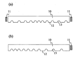
図3(a)、(b)は、導光板10の端面10aに対向して配列される光源11と、光偏向面12に配列される光偏向要素13の配列パターンの例を表している。
図3(a)は、導光板10の2つの端面10aに対向して光源11が配列され、光源11から第二の方向に離れるにつれてパターンのピッチが小さくなり、導光板10の中央部でパターンのピッチが最小となるような光偏向要素13の配列パターンを表す図である。
図3(b)は、導光板10の1つの端面10aに対向して光源11が配列され、光源11から第二の方向に離れるにつれてパターンのピッチが小さくなり、光源11に近接して対向する端面10aとは逆側の端面付近の光偏向面でパターンのピッチが最小となるような光偏向要素13の配列パターンを表す図である。
3A and 3B show examples of arrangement patterns of the light sources 11 arranged facing the end face 10a of the light guide plate 10 and the light deflection elements 13 arranged on the light deflection surface 12. FIG.
In FIG. 3A, the light source 11 is arranged facing the two end faces 10 a of the light guide plate 10, and the pattern pitch decreases as the distance from the light source 11 in the second direction becomes smaller. It is a figure showing the arrangement pattern of the light deflection | deviation element 13 that the pitch of becomes the minimum.
In FIG. 3B, the light source 11 is arranged facing one end face 10 a of the light guide plate 10, and the pattern pitch decreases as the distance from the light source 11 in the second direction becomes closer to the light source 11. It is a figure showing the arrangement pattern of the optical deflection | deviation element 13 in which the pitch of a pattern becomes the minimum in the optical deflection surface near the end surface on the opposite side to the end surface 10a.

ここで、光源11に近接して対向する端面10a近傍で、光偏向要素13の配列のピッチをあまり広げると、導光板10の上に、前述の図6で説明した拡散シート190やBEFで代表されるレンズシート191、また、反射型偏光分離シート5などを載せても、光偏向要素13が明るい輝線として視認されてしまう場合がある。それに対して、本発明における照明ユニットでは、BEF185や類似のレンズシート191の代わりに、後述する拡散集光シート4を配置することで、導光板10の光偏向要素13を視認できなくすることが可能になる。   Here, if the pitch of the arrangement of the light deflection elements 13 is increased too much in the vicinity of the end face 10a that is close to and opposed to the light source 11, the diffusion sheet 190 or BEF described above with reference to FIG. Even if the lens sheet 191 or the reflective polarization separation sheet 5 is placed, the light deflection element 13 may be visually recognized as a bright bright line. On the other hand, in the illumination unit according to the present invention, it is possible to make the light deflection element 13 of the light guide plate 10 invisible by disposing the diffusion condensing sheet 4 described later instead of the BEF 185 and the similar lens sheet 191. It becomes possible.

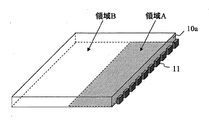
図4は、本発明の実施形態による領域の区分けを説明するために示す、拡散集光シートを備えた照明ユニットの斜視図である。図4に示すように、導光板10の光偏向面12に配列された光偏向要素13のピッチが500μm以上の領域を領域Aとし、ピッチが500μm未満の領域を領域Bとする。一般的に、表示装置に対する人の眼の分解能の制約のため、500μm以上の大きさの画像はそれより小さい画像より視認し易くなる境界値と位置付けられるので、光偏向要素13のピッチによる領域区分を500μmで分けて対応するものである。   FIG. 4 is a perspective view of an illumination unit including a diffusing and condensing sheet, which is shown for explaining the division of regions according to the embodiment of the present invention. As shown in FIG. 4, a region where the pitch of the light deflection elements 13 arranged on the light deflection surface 12 of the light guide plate 10 is 500 μm or more is a region A, and a region where the pitch is less than 500 μm is a region B. In general, because of the limitation of the resolution of the human eye with respect to the display device, an image having a size of 500 μm or more is positioned as a boundary value that is easier to visually recognize than a smaller image. Are divided by 500 μm.

前述の導光板内の光の伝播と散乱に関する説明に従えば、エッジライト方式において散乱光の傾向による輝度ムラを解消するために、光源11から導光板に光を取り込む端面10aに近い領域を光偏向要素13のピッチが大きい領域Aとして、光源から遠ざかる領域を光偏向要素13のピッチが小さい領域Bとすることが妥当である。導光板より観察側に設けて光の拡散と輝度向上とを両立させる拡散集光シート4は、一般的に視認され易いピッチが500μm以上の領域Aの光偏向要素13を視認できなくすることを目的として、領域Aから射出した光を、領域Bから射出した光よりも広い角度分布で、一次元方向、もしくは二次元方向に拡散することを特徴とする。すなわち、領域Aから射出した視認され易い配列パターンの光を、拡散集光シート4で、他の領域より強く拡散することにより、領域Aで発生しピッチが大きいため目立ち易い光偏向要素13の像を拡散し、目立たなくすることが可能になる。一方、領域Bでは、もともと光偏向要素13のピッチが狭いため、領域Bから射出した光は集光拡散シート4であまり拡散しなくても、光偏向要素13の像は目立たない。   According to the above description regarding the propagation and scattering of light in the light guide plate, in order to eliminate luminance unevenness due to the tendency of scattered light in the edge light method, a region close to the end surface 10a that takes light from the light source 11 to the light guide plate is lighted. As the region A where the pitch of the deflecting elements 13 is large, it is appropriate that the region away from the light source is the region B where the pitch of the light deflecting elements 13 is small. The diffusion condensing sheet 4 provided on the observation side of the light guide plate to achieve both the diffusion of light and the improvement in luminance prevents the light deflection element 13 in the region A having a pitch of 500 μm or more, which is generally easily visible, from being visible. As an object, the present invention is characterized in that light emitted from the region A is diffused in a one-dimensional direction or a two-dimensional direction with a wider angular distribution than the light emitted from the region B. In other words, the light of the arrangement pattern that is easily visible that is emitted from the area A is diffused more strongly than the other areas by the diffusion condensing sheet 4, so that the image of the light deflection element 13 that is generated in the area A and is conspicuous due to the large pitch. Can be diffused and made inconspicuous. On the other hand, in the region B, since the pitch of the light deflection elements 13 is originally narrow, even if the light emitted from the region B is not diffused so much by the condensing diffusion sheet 4, the image of the light deflection elements 13 is not conspicuous.

図5は、本発明における拡散集光シート4の例を導光板の領域Aおよび領域Bとの関係で表す模式断面図であって、(a)は、領域によりレンズまたはプリズムを並び分ける例であり、(b)は、領域により選択的に粗面を形成する例である。   FIG. 5 is a schematic cross-sectional view showing an example of the diffusing and condensing sheet 4 in the present invention in relation to the region A and the region B of the light guide plate. FIG. 5A is an example in which lenses or prisms are arranged according to the region. Yes, (b) is an example in which a rough surface is selectively formed by a region.

図5(a)に図示するように、拡散集光シート4の一例として、拡散集光シート4の光射出面の領域Aに対向する領域をA’とすると、領域A’上に円柱状の曲面により形成された複数のレンズを第一の方向に平行に延在するように配列する。さらに、拡散集光シート4の光射出面の領域Bに対向する領域をB’とすると、領域B’上に断面が三角形状の複数のプリズムが第一の方向に平行に延在するように配列する。領域A’には曲面レンズが配列されているため、領域Aから射出した光を拡散し、光偏向要素13の像を目立たなくすることができる。領域B’に配列されているプリズムは光を拡散させずに集光する効果があるので、拡散集光シート4の輝度上昇に寄与する。   As shown in FIG. 5A, as an example of the diffusing and condensing sheet 4, when a region facing the region A on the light exit surface of the diffusing and condensing sheet 4 is A ′, a cylindrical shape is formed on the region A ′. A plurality of lenses formed by curved surfaces are arranged so as to extend in parallel to the first direction. Furthermore, when the region facing the region B on the light exit surface of the diffusing and condensing sheet 4 is B ′, a plurality of prisms having a triangular cross section extend in parallel to the first direction on the region B ′. Arrange. Since the curved lens is arranged in the area A ′, the light emitted from the area A can be diffused and the image of the light deflection element 13 can be made inconspicuous. Since the prisms arranged in the region B ′ have an effect of collecting light without diffusing light, it contributes to an increase in luminance of the diffusing and collecting sheet 4.

あるいは、拡散集光シート4の光射出面の全面に断面が三角形状の複数のプリズムを第一の方向に平行に延在するように配列し、領域A’上の複数のプリズムの表面に、光拡散層を形成しても良い。プリズム表面の光拡散層によって、領域A’は領域Aから射出した光を拡散し、光偏向要素13の像を目立たなくすることができる。領域B’に配列されるプリズムには光拡散層が形成されなくても、対向する領域Bの光偏向要素13のピッチが狭いため、光偏向要素13が視認されることは無い。また、領域B’に配列されるプリズムの集光効果によって、拡散集光シート4の輝度上昇に寄与する。   Alternatively, a plurality of prisms having a triangular cross section are arranged so as to extend in parallel with the first direction on the entire surface of the light exit surface of the diffusing and condensing sheet 4, and on the surfaces of the plurality of prisms on the region A ′, A light diffusion layer may be formed. By the light diffusing layer on the prism surface, the region A ′ can diffuse the light emitted from the region A and make the image of the light deflection element 13 inconspicuous. Even if the light diffusing layer is not formed on the prisms arranged in the region B ′, the light deflection elements 13 are not visually recognized because the pitch of the light deflection elements 13 in the facing region B is narrow. Further, the light collecting effect of the prisms arranged in the region B ′ contributes to an increase in luminance of the diffusing light collecting sheet 4.

あるいは、拡散集光シート4の光射出面の全面に円柱状の曲面により形成された複数のレンズを第一の方向に平行に延在するように配列し、領域A’上の複数のレンズの表面に光拡散層を形成しても良い。レンズの拡散効果と光拡散層の拡散効果の両方により、領域Aから射出した光を拡散するので、領域Aに配列される光偏向要素13を効果的に目立たなくすることができる。また、領域B’に配列される複数のレンズは、プリズムほどではないが集光効果を有するため、正面輝度向上に寄与する。   Alternatively, a plurality of lenses formed by a cylindrical curved surface are arranged on the entire light exit surface of the diffusion condensing sheet 4 so as to extend in parallel with the first direction, and the plurality of lenses on the region A ′ are arranged. A light diffusion layer may be formed on the surface. Since the light emitted from the region A is diffused by both the diffusion effect of the lens and the diffusion effect of the light diffusion layer, the light deflection elements 13 arranged in the region A can be effectively made inconspicuous. In addition, the plurality of lenses arranged in the region B ′ has a light condensing effect although not as much as a prism, and thus contributes to an improvement in front luminance.

あるいは、図5(b)に図示するように、拡散集光シート4の光入射面の内、領域Aと対向する領域A”上に、粗面を形成しても良い。粗面を形成することで、領域Aから射出した光が領域A”で拡散されるので、領域Aの光偏向要素13を目立たなくすることができる。領域Bと対向する領域B”は、完全な平坦面としても良いし、領域A”より拡散性の弱い粗面を形成しても良い。また、本例のように、粗面の選択的形成により画像の拡散性に差をつける手法にあっては、拡散集光シート4の輝度向上面の機能は、上記の例と同様な方法で実現できる。すなわち、拡散集光シート4の光射出面の全面に断面が三角形状の複数のプリズムを第一の方向に平行に延在するように配列するか、あるいは、拡散集光シート4の光射出面の全面に円柱状の曲面により形成された複数のレンズを第一の方向に平行に延在するように配列することにより、拡散集光シートに一定の集光効果を付与することができ、照明ユニットの輝度向上に寄与することができる。   Alternatively, as illustrated in FIG. 5B, a rough surface may be formed on the region A ″ facing the region A in the light incident surface of the diffusion condensing sheet 4. The rough surface is formed. Thus, since the light emitted from the region A is diffused in the region A ″, the light deflection element 13 in the region A can be made inconspicuous. The region B ″ facing the region B may be a completely flat surface, or a rough surface having a lower diffusibility than the region A ″ may be formed. In addition, as in this example, in the method of making a difference in image diffusibility by selectively forming a rough surface, the function of the brightness enhancement surface of the diffusion condensing sheet 4 is the same as in the above example. realizable. That is, a plurality of prisms having a triangular cross section are arranged on the entire surface of the light exit surface of the diffusion light collection sheet 4 so as to extend parallel to the first direction, or the light emission surface of the diffusion light collection sheet 4 By arranging a plurality of lenses formed by cylindrical curved surfaces on the entire surface so as to extend in parallel with the first direction, it is possible to give a certain light collection effect to the diffusion light collection sheet, This can contribute to improvement of the brightness of the unit.

あるいは、拡散集光シート4の光入射面の内、領域Aと対向する領域A”上に、粗面に替えて、第二の方向に拡散性を有する指向性拡散層を形成しても良い。   Alternatively, a directional diffusion layer having diffusivity in the second direction may be formed on the region A ″ facing the region A in the light incident surface of the diffusion condensing sheet 4 instead of the rough surface. .

本実施形態による照明ユニット7に含まれる導光板10は、透明性の高いアクリル系の材料を用いるのが良く、特にPMMA(ポリメチルメタクリレート)は透明性が高いため好ましい。但し、透明性の高い材料であれば、これに限定されることはない。導光板10は、この技術分野では良く知られている押出成形法、射出成型法、あるいは熱プレス成型法によって成型する。導光板10の光偏向面12に形成される光偏向要素13は、これらの方法で一体成型することができる。光偏向要素13は、例えばプリズム形状やレンズ形状を機械切削等で形成した金型の版、もしくは、UV硬化樹脂や放射線硬化樹脂等を用いてレンズ形状を成形した樹脂版の型を使用して、成型する樹脂材料と樹脂版の型を圧着させて成型する方法でも良い。   The light guide plate 10 included in the illumination unit 7 according to the present embodiment is preferably made of a highly transparent acrylic material, and in particular, PMMA (polymethyl methacrylate) is preferable because of its high transparency. However, the material is not limited to this as long as the material has high transparency. The light guide plate 10 is molded by an extrusion molding method, an injection molding method, or a hot press molding method well known in this technical field. The light deflection element 13 formed on the light deflection surface 12 of the light guide plate 10 can be integrally molded by these methods. The light deflection element 13 uses, for example, a mold plate in which a prism shape or a lens shape is formed by mechanical cutting or the like, or a resin plate die in which a lens shape is molded using a UV curable resin or a radiation curable resin. Alternatively, a method may be employed in which the resin material to be molded and the mold of the resin plate are pressure bonded.

本実施形態による照明ユニット7に含まれる拡散集光シート4は、UV硬化樹脂や放射線硬化樹脂等を用いて成形されるか、またはPET(ポリエチレンテレフタレート)、PC(ポリカーボネート)、PMMA(ポリメチルメタクリレート)、COP(シクロオレフィンポリマー)、PAN(ポリアクリロニトリル共重合体)、AS(アクリロニトリルスチレン共重合体)等を用いて、この技術分野では良く知られている押出成形法、射出成型法、あるいは熱プレス成型法によって一体で形成することができる。あるいは、UV硬化樹脂や放射線硬化樹脂等を用いてレンズ形状を成形した樹脂版の型を使用して、成型する樹脂材料と樹脂版の型を圧着させて押し出すことにより成型しても良い。   The diffusion condensing sheet 4 included in the illumination unit 7 according to the present embodiment is molded using a UV curable resin, a radiation curable resin, or the like, or PET (polyethylene terephthalate), PC (polycarbonate), PMMA (polymethyl methacrylate). ), COP (cycloolefin polymer), PAN (polyacrylonitrile copolymer), AS (acrylonitrile styrene copolymer), etc., which are well known in this technical field such as extrusion molding, injection molding, or heat It can be formed integrally by a press molding method. Alternatively, a resin plate mold in which a lens shape is formed using a UV curable resin, a radiation curable resin, or the like may be used, and the resin material to be molded and the resin plate mold may be pressed and extruded.

領域A’上のプリズム、もしくは曲面レンズの表面に光拡散層を選択的に形成する方法としては、プリズム、もしくは曲面レンズを機械切削等で切削した金型に、サンドブラスト等のブラスト処理を選択的に行うことによって粗面を形成する方法がある。表面が荒れたプリズム、もしくは曲面レンズは拡散性を有するため、光偏向要素13を効果的に目立たなくすることができる。あるいは、成型した拡散集光シート4のプリズム、もしくは曲面レンズの表面に、拡散フィラーを混入した層を選択的にコーティングすることで、拡散層を形成しても良い。   As a method of selectively forming the light diffusion layer on the surface of the prism or curved lens in the area A ′, a blasting process such as sand blasting is selectively applied to a mold obtained by cutting the prism or curved lens by mechanical cutting or the like. There is a method of forming a rough surface by performing the above. Since the prism having a rough surface or the curved lens has diffusibility, the light deflection element 13 can be effectively made inconspicuous. Alternatively, the diffusion layer may be formed by selectively coating the surface of the molded diffusion condensing sheet 4 on the prism or curved lens with a layer mixed with a diffusion filler.

領域A”に形成される粗面としては、例えばサンドブラスト等のブラスト処理によって形成した2次元的な粗面を形成しても良いし、或いは、球の一部からなるマイクロレンズを形成しても良い。また、指向性拡散層としては、ヘアラインのような微細なピッチで形成された直線状の凹凸構造や、楕円体の一部からなるマイクロレンズ、或いは、互いに平行に配列した波型形状の凹凸構造を形成しても良い。或いは、針状のフィラーを互いに方向を揃えてコーティングする方法でも良い。   As the rough surface formed in the region A ″, for example, a two-dimensional rough surface formed by blasting such as sandblasting may be formed, or a microlens made of a part of a sphere may be formed. In addition, as the directional diffusion layer, a linear concavo-convex structure formed with a fine pitch such as a hairline, a microlens formed of a part of an ellipsoid, or a corrugated shape arranged in parallel to each other. An uneven structure may be formed, or a method of coating needle-shaped fillers with their directions aligned with each other may be used.

また、液晶表示素子6で例示した画像表示素子は、画素単位で光を透過/遮光して画像を表示する素子であることが好ましい。画素単位で光を透過/遮光して画像を表示するものであれば、本実施形態による照明ユニット7により、画像表示素子を透過する画像の視覚方向Fへの輝度が向上し、光強度の視角度依存性が低減する。さらに、本実施形態による照明ユニット7により、光偏向要素13が視認できなくなり、画像品位の高い画像を表示させることができる。   The image display element exemplified as the liquid crystal display element 6 is preferably an element that displays an image by transmitting / blocking light in pixel units. If the image is displayed by transmitting / blocking light in pixel units, the illumination unit 7 according to the present embodiment improves the luminance of the image transmitted through the image display element in the visual direction F, and the light intensity is viewed. Angle dependency is reduced. Furthermore, the illumination unit 7 according to the present embodiment makes it impossible to visually recognize the light deflection element 13, and an image with high image quality can be displayed.

さらに、照明ユニット7に反射型偏光分離シートを載せて、照明装置8が構成される。反射型偏光分離シートとして、例えばDBEF(3M社登録商標)に代表されるような反射型偏光分離シートが使用できる。反射型偏光分離シートは、液晶パネルの偏光板で吸収される偏光成分を持つ光を反射し、偏光板を透過する偏光成分を持つ光のみを透過させることができるため、液晶ディスプレイの輝度を効率的に高めることができる。   Further, the illumination device 8 is configured by placing a reflective polarization separation sheet on the illumination unit 7. As the reflective polarization separation sheet, for example, a reflective polarization separation sheet represented by DBEF (registered trademark of 3M) can be used. Reflective polarized light separation sheet reflects the light with the polarization component absorbed by the polarizing plate of the liquid crystal panel and transmits only the light with the polarization component that passes through the polarizing plate. Can be enhanced.

なお、画像表示素子は液晶表示素子6であることが好ましい。図1に示すように、液晶表示素子6は液晶パネル22の前後に偏光板23,23が積層して構成されている。液晶表示素子6は画素単位で光を透過/遮光して画像を表示する代表的な素子であり、他の表示素子に比べて画像品位を高くすることができるとともに、製造コストを低減することができる。   The image display element is preferably a liquid crystal display element 6. As shown in FIG. 1, the liquid crystal display element 6 is configured by laminating polarizing plates 23 and 23 before and after a liquid crystal panel 22. The liquid crystal display element 6 is a typical element that transmits / shields light in pixel units and displays an image. The liquid crystal display element 6 can improve image quality as compared with other display elements and can reduce manufacturing costs. it can.

なお、本発明における拡散集光シート4は、テレビ等の液晶表示装置1として以外にも、例えば、室内や屋外の照明用途としても利用できる。特に、拡散集光シート4を組み込んだ照明ユニット7は、明るさのムラがなく正面輝度の高い光を発光できるので、屋内や屋外の特定空間を均一に明るく照明することができる。   In addition, the diffusion condensing sheet 4 in the present invention can be used not only as the liquid crystal display device 1 such as a television but also for indoor and outdoor lighting applications, for example. In particular, the illumination unit 7 incorporating the diffusion condensing sheet 4 can emit light with high front brightness without unevenness in brightness, and therefore can illuminate a specific indoor or outdoor space uniformly and brightly.

次に、本発明の実施例として、実施例1〜3による拡散集光シート4と比較例1による拡散集光シート4を製作して、それぞれを液晶表示装置1の照明装置8に組み込んで正面輝度の評価と、光偏向要素13の視認性の評価を行った。   Next, as examples of the present invention, the diffused condensing sheet 4 according to Examples 1 to 3 and the diffused condensing sheet 4 according to Comparative Example 1 were manufactured, and each was incorporated into the illumination device 8 of the liquid crystal display device 1. Evaluation of luminance and visibility of the light deflection element 13 were performed.

<面光源装置2の作製>
面光源装置2を以下のように作製した。
まず、光偏向面12に断面が三角形状の溝が形成された、3mm厚の導光板10を用意し、光源11として複数個のLEDを導光板10の一辺の厚み方向の端面10aに対向するように一列に配列した。導光板10は、LEDと対面する辺の長さが550mm、それと直交する辺の長さが310mmの板とした。
導光板10の光偏向面12には、頂角90°で断面が三角形状の複数の溝を、LEDと対面する端面10aと平行な方向に延在するように配列した。溝の配列ピッチは、LED側から離れるにつれて直線的に減少するように設計し、LED側の端面10aの最近傍で800μm、LEDと逆側の端面10aの最近傍で60μmとなるように、配列した。断面三角形状の溝の幅は50μm、溝の深さは25μmとした。
導光板10の材料としてPMMA樹脂を用い、PMMA樹脂の押し出し成型により導光板10の光偏向要素13を一体で成型した。光偏向要素13は、断面三角形状の突起が形成された樹脂版を、溶融したPMMA樹脂に押し当てて成型することで、作製した。樹脂版
は、機械切削によりプリズム状の溝を形成したロールからUV硬化樹脂でPET基材上に反転形状を転写することにより作製した。
導光板10の光偏向面12側の背面には反射シート9を配置することで、面光源装置2を得た。
<Production of surface light source device 2>
The surface light source device 2 was produced as follows.
First, a 3 mm-thick light guide plate 10 having a groove having a triangular cross section formed on the light deflection surface 12 is prepared, and a plurality of LEDs are opposed to the end surface 10 a in the thickness direction of one side of the light guide plate 10 as the light source 11. Arranged in a row. The light guide plate 10 was a plate having a length of 550 mm on the side facing the LED and a length of 310 mm on a side perpendicular to the LED.
On the light deflection surface 12 of the light guide plate 10, a plurality of grooves having an apex angle of 90 ° and a triangular cross section were arranged so as to extend in a direction parallel to the end surface 10a facing the LED. The groove pitch is designed to decrease linearly as the distance from the LED side increases, and the groove pitch is 800 μm in the vicinity of the end face 10a on the LED side and 60 μm in the vicinity of the end face 10a opposite to the LED. did. The width of the groove having a triangular cross section was 50 μm, and the depth of the groove was 25 μm.
PMMA resin was used as the material of the light guide plate 10, and the light deflection element 13 of the light guide plate 10 was integrally molded by extrusion molding of PMMA resin. The light deflection element 13 was produced by pressing and molding a resin plate on which protrusions having a triangular cross section were formed against molten PMMA resin. The resin plate was produced by transferring the inverted shape onto a PET substrate with a UV curable resin from a roll in which prismatic grooves were formed by mechanical cutting.
The surface light source device 2 was obtained by arranging the reflection sheet 9 on the back surface of the light guide plate 10 on the light deflection surface 12 side.

<拡散集光シート4の作製>
拡散集光シート4の材料としてポリカーボネート樹脂を用いた。ポリカーボネート樹脂は屈折率が約1.59と高いため、正面輝度の高い拡散集光シート4を得ることが出来る。拡散集光シート4は、ポリカーボネート樹脂を用いて押し出し成型により形成した。
実施例1〜3、比較例1による拡散集光シート4の具体的な構成は後述する。
<Preparation of diffusion condensing sheet 4>
A polycarbonate resin was used as the material of the diffusion condensing sheet 4. Since the polycarbonate resin has a high refractive index of about 1.59, it is possible to obtain the diffusion condensing sheet 4 having high front luminance. The diffusion condensing sheet 4 was formed by extrusion molding using a polycarbonate resin.
Specific configurations of the diffusion condensing sheets 4 according to Examples 1 to 3 and Comparative Example 1 will be described later.

<照明装置8の作製>
照明装置8は以下のように作製した。
先ず、面光源装置2の光射出面側に拡散シート3を配置して、さらにその光射出面側に拡散集光シート4を配置して照明ユニット7を作製する。拡散シート3は、全光線透過率60%、Hz85%で、PET基材の上に拡散微粒子をコーティングしたフィルムを使用した。
さらに、拡散シート3の上に、拡散集光シート4を配設した。更にその上に反射型偏光分離シート5としてDBEF(3M社製)を配置することで、照明装置8を得た。
<Production of lighting device 8>
The lighting device 8 was produced as follows.
First, the diffusing sheet 3 is arranged on the light emitting surface side of the surface light source device 2, and the diffusing and condensing sheet 4 is arranged on the light emitting surface side to produce the illumination unit 7. The diffusion sheet 3 was a film having a total light transmittance of 60% and Hz of 85%, and a coating of diffusion fine particles on a PET substrate.
Further, a diffusion condensing sheet 4 was disposed on the diffusion sheet 3. Furthermore, DBEF (made by 3M company) was arrange | positioned as the reflection type polarization separation sheet 5 on it, and the illuminating device 8 was obtained.

実施例1〜3、および比較例1による拡散集光シート4の作製条件は、以下のとおりである。
(実施例1)
拡散集光シート4の光射出面の領域A’に、ピッチ50μm、高さ23μm、頂部の曲率半径が12μmの曲面レンズを形成した。領域B’には、ピッチ50μm、高さ25μmのプリズムを形成した。拡散集光シート4の光入射面は平坦面とした。
(実施例2)
拡散集光シート4の光射出面には、全面にピッチ50μm、高さ25μmのプリズムを形成した。光入射面の領域A”に表面粗さRzが6.0μmの粗面を形成した。領域B”は、平坦面とした。
(実施例3)
拡散集光シート4の光射出面には、全面にピッチ50μm、高さ25μmのプリズムを形成した。光入射面には、領域A”に指向性拡散層を形成した。指向性拡散層として、アスペクト比(高さ/ピッチ)が0.08でピッチが20μm、断面が円の一部からなる曲面レンズを、端面10aと平行な方向に配列した。領域B”は、平坦面とした。
The production conditions of the diffusion condensing sheet 4 according to Examples 1 to 3 and Comparative Example 1 are as follows.
Example 1
A curved lens having a pitch of 50 μm, a height of 23 μm, and a top radius of curvature of 12 μm was formed in the region A ′ of the light exit surface of the diffusion condensing sheet 4. In the region B ′, prisms having a pitch of 50 μm and a height of 25 μm were formed. The light incident surface of the diffusion condensing sheet 4 was a flat surface.
(Example 2)
A prism having a pitch of 50 μm and a height of 25 μm was formed on the entire surface of the light exit surface of the diffusion condensing sheet 4. A rough surface having a surface roughness Rz of 6.0 μm was formed in the region A ″ of the light incident surface. The region B ″ was a flat surface.
(Example 3)
A prism having a pitch of 50 μm and a height of 25 μm was formed on the entire surface of the light exit surface of the diffusion condensing sheet 4. On the light incident surface, a directional diffusion layer was formed in the region A ″. As the directional diffusion layer, a curved surface having an aspect ratio (height / pitch) of 0.08, a pitch of 20 μm, and a cross section consisting of a part of a circle. The lenses were arranged in a direction parallel to the end face 10a. The region B ″ was a flat surface.

(比較例1)
拡散集光シート4の光射出面に、全面にピッチ50μm、高さ25μmのプリズムを形成した。また、光入射面の全面に渡って、表面粗さRzが6.0μmの粗面を形成した。
(Comparative Example 1)
A prism having a pitch of 50 μm and a height of 25 μm was formed on the entire surface of the light exit surface of the diffusion condensing sheet 4. Further, a rough surface having a surface roughness Rz of 6.0 μm was formed over the entire light incident surface.

<正面輝度の評価>
次に、照明装置8として、面光源装置2に拡散シート3と、さらにその光射出面側に比較例1、実施例1〜3による拡散集光シート4をそれぞれ載せ、その上に反射型偏光分離シート5としてDBEFを載せて照明装置8をそれぞれ組み立てた。
そして、比較例、実施例1〜3による照明装置8の外観評価と、正面輝度の測定を行った。正面輝度の測定に際して、輝度測定器として(株)トプコン製の分光放射輝度計SR3を使用した。
評価に際して、正面輝度は、比較例を用いた照明装置8の正面輝度の測定値を1とした。
<Evaluation of front brightness>
Next, as the illuminating device 8, the diffusion sheet 3 is mounted on the surface light source device 2, and the diffusion condensing sheets 4 according to Comparative Example 1 and Examples 1 to 3 are mounted on the light exit surface side, respectively, and the reflective polarized light is mounted thereon. DBEF was mounted as the separation sheet 5 and the lighting devices 8 were assembled.
And the external appearance evaluation of the illuminating device 8 by a comparative example and Examples 1-3 and the measurement of front luminance were performed. When measuring the front luminance, a spectral radiance meter SR3 manufactured by Topcon Corporation was used as a luminance measuring device.
At the time of evaluation, the measured value of the front luminance of the lighting device 8 using the comparative example was set to 1.

実施例1の正面輝度を測定した結果、1.075が得られた。
実施例2の正面輝度を測定した結果、1.040が得られた。
実施例3の正面輝度を測定した結果、1.055が得られた。
実施例1〜3における照明装置8の外観評価を行った結果、全てにおいて、光偏向要素13は視認されなかった。
As a result of measuring the front luminance of Example 1, 1.075 was obtained.
As a result of measuring the front luminance of Example 2, 1.040 was obtained.
As a result of measuring the front luminance of Example 3, 1.055 was obtained.
As a result of the external appearance evaluation of the lighting device 8 in Examples 1 to 3, the light deflection element 13 was not visually recognized in all.

以上の実施例1〜3、比較例1の測定結果より、実施例1〜3における拡散集光シート4を組み込んだ照明装置8の正面輝度は、比較例1を組み込んだものと比べて、正面輝度が上昇し、なおかつ光偏向要素13が視認されないことを実証できた。   From the measurement results of Examples 1 to 3 and Comparative Example 1 above, the front luminance of the illuminating device 8 incorporating the diffusing and condensing sheet 4 in Examples 1 to 3 is the front luminance compared to that incorporating the Comparative Example 1. It was proved that the luminance increased and the light deflection element 13 was not visually recognized.

1・・・液晶表示装置
2・・・面光源装置
3・・・拡散シート
4・・・拡散集光シート
5・・・反射型偏光分離シート
6・・・液晶表示素子
7・・・照明ユニット、
8・・・照明装置
9・・・反射シート
10・・・導光板
10a・・・端面
10b・・・射出面
11・・・光源
12・・・光偏向面
13・・・光偏向要素
22・・・液晶パネル
23・・・偏光板
100・・・導光板
100a・・・射出面
100b・・・光偏向面
101・・・光源
102・・・光偏向要素
182・・・面光源
184・・・液晶表示素子
185・・・BEF
186・・・透明基材
187・・・プリズム
190・・・拡散シート
191・・・レンズシート(BEF)
200・・・液晶表示装置
DESCRIPTION OF SYMBOLS 1 ... Liquid crystal display device 2 ... Surface light source device 3 ... Diffusion sheet 4 ... Diffusion condensing sheet 5 ... Reflection type polarization separation sheet 6 ... Liquid crystal display element 7 ... Illumination unit ,
DESCRIPTION OF SYMBOLS 8 ... Illuminating device 9 ... Reflective sheet 10 ... Light guide plate 10a ... End surface 10b ... Ejection surface 11 ... Light source 12 ... Light deflection surface 13 ... Light deflection element 22- .. Liquid crystal panel 23... Polarizing plate 100... Light guide plate 100 a.・ Liquid crystal display element 185... BEF
186: Transparent substrate 187 ... Prism 190 ... Diffusion sheet 191 ... Lens sheet (BEF)
200: Liquid crystal display device

Claims (8)

光源と、
光源から射出される光を入射する端面と入射した光を観察側へと射出する射出面と入射した光を射出面へと導く光偏向面とを備えた導光板と、
射出面を除く導光板の面から射出する光を反射して導光板へと導く反射シートと、
を備えた面光源装置と、
面光源装置の射出面側に設けて入射した光を二次元方向に拡散する拡散シートと、
拡散シートの観察側に設けて光の拡散と輝度向上とを両立させる拡散集光シートと、
からなる照明ユニットであって、
導光板は、光偏向面に、該導光板に入射された光を射出面側へと導く光偏向要素を備え、光偏向要素は、端面と平行な第一の方向に延在し、端面と垂直な第二の方向に配列してなる一次元配列で配置され、導光板は、光偏向要素の配列ピッチが500μm以上の領域Aと500μm未満の領域Bの2つの領域に分けられ、
拡散集光シートは、領域Aから射出した光を、領域Bから射出した光よりも広い角度分布で、一次元方向、もしくは二次元方向に拡散することを特徴とする照明ユニット。
A light source;
A light guide plate comprising an end face for incident light emitted from a light source, an emission surface for emitting incident light to the observation side, and a light deflection surface for guiding incident light to the emission surface;
A reflection sheet that reflects light emitted from the surface of the light guide plate excluding the exit surface and guides it to the light guide plate;
A surface light source device comprising:
A diffusion sheet that is provided on the exit surface side of the surface light source device and diffuses incident light in a two-dimensional direction;
A diffusion condensing sheet that is provided on the observation side of the diffusion sheet to achieve both light diffusion and brightness improvement;
A lighting unit comprising:
The light guide plate includes, on the light deflection surface, a light deflection element that guides light incident on the light guide plate to the exit surface side, the light deflection element extending in a first direction parallel to the end surface, Arranged in a one-dimensional arrangement arranged in a second vertical direction, the light guide plate is divided into two areas, an area A in which the arrangement pitch of the light deflection elements is 500 μm or more and an area B in which the arrangement pitch is less than 500 μm.
The diffusion condensing sheet diffuses light emitted from the region A in a one-dimensional direction or a two-dimensional direction with a wider angular distribution than the light emitted from the region B.
拡散集光シートの観察側に面した光射出面の内、領域Aに対向する領域には、円柱状の曲面により形成された複数のレンズが第一の方向に延在するように配列され、拡散集光シートの観察側に面した光射出面の内、領域Bに対向する領域には、断面が三角形状の複数のプリズムが第一の方向に延在するように配列されることを特徴とする請求項1に記載の照明ユニット。   Of the light exit surface facing the observation side of the diffusion condensing sheet, in a region facing the region A, a plurality of lenses formed by a cylindrical curved surface are arranged to extend in the first direction, Of the light exit surface facing the observation side of the diffusion condensing sheet, a plurality of prisms having a triangular cross section are arranged so as to extend in the first direction in a region facing the region B. The lighting unit according to claim 1. 拡散集光シートの観察側に面した光射出面に、断面が三角形状の複数のプリズムが第一の方向に延在するように配列され、領域Aに対向する拡散集光シートの領域に配列される複数のプリズムの表面には光拡散層が形成されていることを特徴とする請求項1に記載の照明ユニット。   A plurality of prisms having a triangular cross section are arranged to extend in the first direction on the light exit surface facing the observation side of the diffusion condensing sheet, and arranged in the region of the diffusion condensing sheet facing the region A The illumination unit according to claim 1, wherein a light diffusion layer is formed on surfaces of the plurality of prisms. 拡散集光シートの観察側に面した光射出面に、円柱状の曲面により形成された複数のレンズが第一の方向に延在するように配列され、領域Aに対向する拡散集光シートの領域に配列される複数のレンズの表面には光拡散層が形成されていることを特徴とする請求項1に記載の照明ユニット。   A plurality of lenses formed by a cylindrical curved surface are arranged to extend in the first direction on the light exit surface facing the observation side of the diffusion condensing sheet, and the diffusion condensing sheet facing the region A The illumination unit according to claim 1, wherein a light diffusion layer is formed on surfaces of the plurality of lenses arranged in the region. 拡散集光シートの拡散シート側に面した光入射面の内、領域Aに対向する領域に、粗面が形成されていることを特徴とする請求項1に記載の照明ユニット。   2. The illumination unit according to claim 1, wherein a rough surface is formed in a region facing the region A in the light incident surface facing the diffusion sheet side of the diffusion condensing sheet. 拡散集光シートの拡散シート側に面した光入射面の内、領域Aに対向する領域に、第二の方向に光を拡散する指向性拡散層が形成されていることを特徴とする請求項1に記載の照明ユニット。   The directional diffusion layer for diffusing light in the second direction is formed in a region facing the region A in the light incident surface facing the diffusion sheet side of the diffusion condensing sheet. The lighting unit according to 1. 請求項1〜6のいずれかに記載の照明ユニットに、該照明ユニットから出射した光を偏光させる反射型偏光分離シートを備えたことを特徴とする照明装置。   An illumination apparatus comprising: the illumination unit according to any one of claims 1 to 6; and a reflective polarization separation sheet that polarizes light emitted from the illumination unit. 請求項1〜6のいずれかに記載の照明ユニット、または、請求項7に記載の照明装置のいずれかを、表示画像を規定する画像表示素子に備えたことを特徴とする表示装置。   A display device comprising the illumination unit according to claim 1 or the illumination device according to claim 7 in an image display element that defines a display image.
JP2011051253A 2011-03-09 2011-03-09 Lighting unit, lighting device, and display device Withdrawn JP2012190582A (en)

Priority Applications (1)

Application Number Priority Date Filing Date Title
JP2011051253A JP2012190582A (en) 2011-03-09 2011-03-09 Lighting unit, lighting device, and display device

Applications Claiming Priority (1)

Application Number Priority Date Filing Date Title
JP2011051253A JP2012190582A (en) 2011-03-09 2011-03-09 Lighting unit, lighting device, and display device

Publications (1)

Publication Number Publication Date
JP2012190582A true JP2012190582A (en) 2012-10-04

Family

ID=47083553

Family Applications (1)

Application Number Title Priority Date Filing Date
JP2011051253A Withdrawn JP2012190582A (en) 2011-03-09 2011-03-09 Lighting unit, lighting device, and display device

Country Status (1)

Country Link
JP (1) JP2012190582A (en)

Cited By (2)

* Cited by examiner, † Cited by third party
Publication number Priority date Publication date Assignee Title
JP2018518699A (en) * 2015-04-24 2018-07-12 スリーエム イノベイティブ プロパティズ カンパニー Optical film
JP2018521335A (en) * 2015-04-24 2018-08-02 スリーエム イノベイティブ プロパティズ カンパニー Graded diffuser

Cited By (3)

* Cited by examiner, † Cited by third party
Publication number Priority date Publication date Assignee Title
JP2018518699A (en) * 2015-04-24 2018-07-12 スリーエム イノベイティブ プロパティズ カンパニー Optical film
JP2018521335A (en) * 2015-04-24 2018-08-02 スリーエム イノベイティブ プロパティズ カンパニー Graded diffuser
US10698138B2 (en) 2015-04-24 2020-06-30 3M Innovative Properties Company Graded diffuser

Similar Documents

Publication Publication Date Title
KR101047754B1 (en) Side Dimming Backlight Unit
KR100942490B1 (en) Light guide panel for LCD back light unit and LCD back light unit thereby
US9523810B2 (en) Illumination device and display device
WO2011043466A1 (en) Image display device
JP2012164583A (en) Light guide plate, surface light source device, and transmission type display device
EP3264146A1 (en) Laminated optical member, lighting device, display device and television receiver
KR100781328B1 (en) Light guide panel for lcd back light unit and lcd back light unit thereby
JP2013206834A (en) Illumination unit using light guide body, and display device having the same
JP2014186913A (en) Lighting unit and display device
JP2010192246A (en) Light diffusion plate, optical sheet, backlight unit, and display device
JP5782806B2 (en) Illumination unit and display device including the same
JP2012079460A (en) Lighting unit using concealment lens sheet and display device equipped with this
JP4815930B2 (en) Light transmissive film, backlight device, and liquid crystal display device
JP2015191686A (en) Light guide, edge light type lighting apparatus and image display device
JP2012190582A (en) Lighting unit, lighting device, and display device
JP5741121B2 (en) A mold for manufacturing an optical lens sheet for controlling an illumination optical path, the sheet manufactured using the mold, a method of manufacturing the sheet using the mold, a liquid crystal display device, and a display
JP5699550B2 (en) LIGHTING UNIT, LIGHTING DEVICE, AND DISPLAY DEVICE HAVING HIDDEN STRUCTURE
JP2014093193A (en) Light guide plate, backlight unit including light guide plate and display device
JP5741166B2 (en) LIGHTING UNIT, LIGHTING DEVICE, AND DISPLAY DEVICE
JP5672833B2 (en) Illumination unit and display device using the same
JP2013191510A (en) Light guide plate, backlight unit and display device
JP2013206595A (en) Light guide plate and lighting device as well as display device using light guide plate
JP5434398B2 (en) Illumination unit and display device provided with concealment structure
CN101320102A (en) Light conducting plate structure with multiple lens incidence surface
JP5533174B2 (en) Illumination unit and display device including the same

Legal Events

Date Code Title Description
A300 Withdrawal of application because of no request for examination

Free format text: JAPANESE INTERMEDIATE CODE: A300

Effective date: 20140513