JP2012189342A - Microspectrometry apparatus - Google Patents
Microspectrometry apparatus Download PDFInfo
- Publication number
- JP2012189342A JP2012189342A JP2011050884A JP2011050884A JP2012189342A JP 2012189342 A JP2012189342 A JP 2012189342A JP 2011050884 A JP2011050884 A JP 2011050884A JP 2011050884 A JP2011050884 A JP 2011050884A JP 2012189342 A JP2012189342 A JP 2012189342A
- Authority
- JP
- Japan
- Prior art keywords
- color
- range
- measurement
- illumination
- light
- Prior art date
- Legal status (The legal status is an assumption and is not a legal conclusion. Google has not performed a legal analysis and makes no representation as to the accuracy of the status listed.)
- Withdrawn
Links
Images

Abstract
Description
本発明は、測定試料の一部を測定範囲としてその測定範囲の分光スペクトルを測定するための顕微分光測定装置に関するものである。 The present invention relates to a microscopic spectrophotometer for measuring a spectroscopic spectrum in a measurement range using a part of a measurement sample as a measurement range.
従来より、対物レンズにより測定試料の拡大像を得て、その拡大像の分光スペクトルを測定するための顕微分光測定装置が提案されている(例えば、特許文献1、2参照。)。この顕微分光測定装置は、測定試料に照明光を照射する照明光学系と、照明光による測定試料からの反射光を分光して、その分光された光の強度を波長ごとに検出して分光スペクトルを取得する分光器とを備えている。
2. Description of the Related Art Conventionally, a microspectrophotometer for obtaining an enlarged image of a measurement sample with an objective lens and measuring a spectrum of the enlarged image has been proposed (see, for example,
このような顕微分光測定装置により目的とする測定範囲内の分光スペクトルのみを測定するうえでは、一般に、照明光学系の光路中や、測定試料から分光器に至るまでの光路中に配置された視野絞りが用いられている。この視野絞りの開口径を調整することにより、測定範囲のみが照射されるように照射範囲を調整したり、測定試料からの反射光から測定範囲外の光を遮蔽するように調整することが可能となり、これによって測定範囲からの反射光のみを分光してその測定範囲の分光スペクトルのみを取得することが可能となる。 In order to measure only a spectral spectrum within the target measurement range using such a microspectrophotometer, generally, the field of view disposed in the optical path of the illumination optical system or in the optical path from the measurement sample to the spectroscope. A diaphragm is used. By adjusting the aperture diameter of this field stop, it is possible to adjust the irradiation range so that only the measurement range is irradiated, or to block light outside the measurement range from the reflected light from the measurement sample As a result, only the reflected light from the measurement range can be dispersed to obtain only the spectrum of the measurement range.
ところで、分光スペクトルを測定しようとする測定範囲の形状は様々であるのに対して、視野絞りの開口形状は、多角形からなる略円形状であったり、細長の矩形状等であったりと、ある程度定まった形状とされている。このため、測定範囲の形状に合わせて適切な視野絞りの開口形状に調整することが困難となり、所望とする測定範囲の分光スペクトルを得られない場合があるという問題点があった。 By the way, while the shape of the measurement range for measuring the spectrum is various, the aperture shape of the field stop is a substantially circular shape made of a polygon, an elongated rectangular shape, etc. It has a certain shape. For this reason, it is difficult to adjust the aperture shape of the appropriate field stop according to the shape of the measurement range, and there is a problem in that it may not be possible to obtain a spectrum of the desired measurement range.
また、測定試料からの分光スペクトルの取得範囲を測定範囲に対して小さな微小な範囲として、測定範囲全体を二次元的に走査することによりその微小範囲毎の分光スペクトルを取得し、各微小範囲の分光スペクトルの光強度を波長成分毎に加算することにより測定範囲全体の分光スペクトルを演算値として算出する方法も考えられる。しかしながら、このような方法によると、測定範囲全体に亘って二次元的に走査することによりその測定範囲内の微小範囲毎の分光スペクトルを取得する必要があるため、測定時間が過度に増大してしまうという問題点があった。 In addition, the spectrum acquisition range from the measurement sample is set to a minute range that is small relative to the measurement range, and the entire measurement range is scanned two-dimensionally to obtain a spectrum for each minute range. A method is also conceivable in which the spectral spectrum of the entire measurement range is calculated as an operation value by adding the light intensity of the spectral spectrum for each wavelength component. However, according to such a method, since it is necessary to acquire a spectrum for each minute range within the measurement range by scanning two-dimensionally over the entire measurement range, the measurement time increases excessively. There was a problem of end.
そこで、本発明は、上述した問題点に鑑みて案出されたものであり、その目的とするところは、視野絞りの開口形状による制限を受けることなく、様々な形状を測定範囲としてその測定範囲の分光スペクトルを測定することを可能としつつ、その測定範囲内の測定を短時間で完了させることのできる顕微分光測定装置を提供することにある。 Therefore, the present invention has been devised in view of the above-described problems, and the object of the present invention is to use various shapes as a measurement range without being limited by the aperture shape of the field stop. Another object of the present invention is to provide a microspectroscopic measurement device that can measure the spectral spectrum of the light and complete the measurement within the measurement range in a short time.
本発明者は、上述した課題を解決するために、鋭意検討の末、下記の顕微分光測定装置を発明した。 In order to solve the above-described problems, the present inventor has invented the following microspectroscopy light measuring apparatus after intensive studies.
第1発明に係る顕微分光測定装置は、測定試料の一部を測定範囲としてその測定範囲の分光スペクトルを測定するための顕微分光測定装置において、前記測定試料を撮像して前記測定範囲を含む撮像範囲のカラー画像情報を取得する撮像手段と、前記カラー画像情報を画像処理することにより、前記測定範囲から色に応じて区分けされる複数の色領域を抽出するとともに、前記複数の色領域の領域面積を算出する画像処理手段と、前記画像処理手段により抽出された色領域の一部を照射範囲として照明光を照射する照明光学系と、前記照射範囲に照射された照明光による反射光又は透過光により前記色領域の一部の分光スペクトルを取得する分光スペクトル取得手段と、前記色領域の領域面積と、前記色領域の一部の分光スペクトルとに基づき演算処理を行なう演算処理手段とを備え、前記照明光学系及び前記分光スペクトル取得手段により前記複数の色領域それぞれの一部の分光スペクトルを取得し、前記演算処理手段は、前記複数の色領域それぞれに対応した領域面積及び一部の分光スペクトルに基づいて、前記測定範囲全体の分光スペクトルを算出することを特徴とする。
第2発明に係る顕微分光測定装置は、第1発明において、前記演算処理手段は、前記分光スペクトル手段により取得された前記色領域の一部の分光スペクトルに基づき単位面積当たりの分光スペクトルを算出し、その算出した色領域の単位面積当たりの分光スペクトルと当該色領域の領域面積を乗算して当該色領域全体の分光スペクトルを算出し、前記複数の色領域それぞれの分光スペクトルを加算して前記測定範囲全体の分光スペクトルを算出することを特徴とする。
第3発明に係る顕微分光測定装置は、第1発明又は第2発明において、前記撮像手段により撮像された画像を表示する表示手段と、前記表示手段により表示された画像から前記測定範囲を設定する設定手段とを更に備えることを特徴とする。
第4発明に係る顕微分光測定装置は、第1発明〜第3発明の何れかにおいて、前記照明光学系から照射される照明光の前記測定試料に対する照射範囲を範囲調整及び位置調整する照射範囲調整手段を更に備え、前記照明範囲調整手段は、前記画像処理手段により抽出された色領域に基づき、その色領域の一部に照明光が照射されるように前記照射範囲を範囲調整及び位置調整することを特徴とする。
第5発明に係る顕微分光測定装置は、第4発明において、前記照明光学系は、前記照明光を射出する光源と、前記光源から射出された照明光の前記測定試料の測定面における照射範囲を範囲調整する視野絞りとを備え、前記照明範囲調整手段は、前記照明光の光軸と直交する方向に一体的に移動可能な前記光源と前記視野絞りとから構成されていることを特徴とする。
A microspectroscopic light measurement apparatus according to a first aspect of the present invention is a microspectroscopic light measurement apparatus for measuring a spectral spectrum of a measurement range using a part of the measurement sample as a measurement range, and imaging the measurement sample and including the measurement range An imaging unit that acquires color image information of a range, and by performing image processing on the color image information, a plurality of color regions that are classified according to color are extracted from the measurement range, and the regions of the plurality of color regions Image processing means for calculating an area, illumination optical system for illuminating illumination light with a part of the color area extracted by the image processing means as an illumination range, and reflected light or transmission by illumination light emitted to the illumination range Spectral spectrum acquisition means for acquiring a spectral spectrum of a part of the color region by light, a region area of the color region, and a spectral spectrum of a part of the color region. Arithmetic processing means for performing arithmetic processing, and acquiring a partial spectrum of each of the plurality of color regions by the illumination optical system and the spectral spectrum acquisition means, the arithmetic processing means, each of the plurality of color regions The spectral spectrum of the whole measurement range is calculated based on the area of the region corresponding to the above and a part of the spectral spectrum.
In the microspectrophotometer according to a second aspect of the present invention, in the first aspect, the arithmetic processing means calculates a spectral spectrum per unit area based on a partial spectral spectrum of the color region acquired by the spectral spectrum means. The spectral spectrum per unit area of the calculated color area is multiplied by the area area of the color area to calculate a spectral spectrum of the entire color area, and the spectral spectrum of each of the plurality of color areas is added to perform the measurement. A spectral spectrum of the entire range is calculated.
The microspectrophotometer according to a third aspect of the present invention is the first aspect or the second aspect, wherein the measurement range is set from the display means for displaying the image picked up by the image pickup means and the image displayed by the display means. And setting means.
The microspectroscopic light measurement apparatus according to a fourth aspect of the present invention is the irradiation range adjustment according to any one of the first aspect to the third aspect, wherein the irradiation range of the illumination light irradiated from the illumination optical system is adjusted and the range is adjusted. And an illumination range adjusting unit that adjusts and adjusts the range of the illumination range based on the color region extracted by the image processing unit so that illumination light is irradiated to a part of the color region. It is characterized by that.
According to a fifth aspect of the present invention, in the fourth aspect, the illumination optical system includes: a light source that emits the illumination light; and an irradiation range on the measurement surface of the measurement sample of the illumination light emitted from the light source. A field stop for adjusting the range, and the illumination range adjusting means includes the light source and the field stop that are integrally movable in a direction orthogonal to the optical axis of the illumination light. .
第1発明〜第5発明によれば、視野絞りの開口形状による制限を受けることなく様々な形状を測定範囲としてその測定範囲の分光スペクトルを測定することが可能となる。また、測定範囲の分光スペクトルを測定するうえで、測定範囲から複数の色領域を画像処理することにより抽出し、その抽出した複数の色領域それぞれの一部について分光スペクトルを取得した後に演算処理を行うのみで足りるため、測定範囲内の測定を短時間で完了させることが可能となる。 According to the first to fifth aspects of the invention, it is possible to measure the spectrum of the measurement range using various shapes as the measurement range without being restricted by the aperture shape of the field stop. In addition, when measuring the spectral spectrum of the measurement range, a plurality of color regions are extracted from the measurement range by performing image processing, and calculation processing is performed after obtaining a spectral spectrum for each of the extracted color regions. Since it is only necessary to perform the measurement, the measurement within the measurement range can be completed in a short time.
以下、本発明を適用した顕微分光測定装置を実施するための形態について、図面を参照しながら詳細に説明する。 Hereinafter, embodiments for implementing a microspectrophotometer to which the present invention is applied will be described in detail with reference to the drawings.
まず、本発明において分光スペクトルを測定する対象となる測定試料について説明する。 First, a measurement sample that is a target for measuring a spectral spectrum in the present invention will be described.
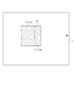
測定試料1は、図1に示すように、分光スペクトルを測定しようとする測定範囲S1内において複数の色領域11を有するものが対象となる。ここでいう色領域11とは、色相、彩度、明度等により表された色に応じて区分けされる領域のことをいい、単一の色領域11は、後述の撮像装置41により取得したカラー画像において、似通った色相、彩度、明度を有する画素群から構成される。
As shown in FIG. 1, the
測定試料1は、第1実施形態において、白色光の照射により発色する発色体が埋め込まれたガラス基板から構成されている。測定試料1は、第1実施形態において、赤色に発色する正方形状の赤色領域11Aと、青色に発色するL字状の青色領域11Bとにより、正方形状の範囲が赤色と青色との混合色で発色するものを例示している。以下においては、この混合色で発色する正方形状の範囲が測定範囲S1であるものとして説明する。なお、この測定範囲S1は、例えば、縦横長さが10μm×10μm以下の大きさとなり、その測定範囲S1の形状は、特に限定されるものではなく、正方形状等の多角形状の他、円形状、不定形状等に形成される。
In the first embodiment, the
次に、第1実施形態に係る顕微分光測定装置3について説明する。
Next, the
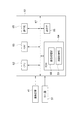
第1実施形態に係る顕微分光測定装置3は、図2に示すように、ステージ20上に載置された測定試料1に照明光を照射する照明光学系29と、測定試料1に照射された照明光による反射光の分光スペクトルを取得する分光スペクトル取得手段としての分光器51と、測定試料1を撮像してカラー画像情報を取得する撮像装置41と、分光器51や撮像装置41を制御する中央制御装置61とを備えている。
As shown in FIG. 2, the microspectroscopic
照明光学系29は、第1実施形態において、照明光を射出する光源30と、光源30から射出された光が対物レンズ36を介して測定試料1の測定面1aに導かれるまでの光路中に順に配置されたコレクタレンズ32と、視野絞り33と、フィールドレンズ35とを有している。また、照明光学系29は、第1実施形態において、光源30からフィールドレンズ35を介して射出された照明光を反射させて、対物レンズ36を介して測定試料1の測定面1aに導く第1ハーフミラー37を更に有している。また、照明光学系29は、光源30から射出された照明光を伝搬させる光ファイバ31を更に備えている。光ファイバ31の出射端31aは、照明光を射出する二次光源として機能しており、その出射端31aから射出された照明光がコレクタレンズ32等を介して測定試料1の測定面1aに導かれる。
In the first embodiment, the illumination
光源11は、例えば、ハロゲンランプ等の白色光を出射するものから構成される。
For example, the
照明光学系29は、第1実施形態において、視野絞り33と測定試料1の測定面1aとが共役な位置に配置されており、これにより、視野絞り33の像が測定試料1の測定面1aに結像されるよう構成されている。これにより、視野絞り33を調整することにより測定試料1の測定面1aに照射される照明光の照射範囲の範囲調整を行うことが可能となる。
In the first embodiment, the illumination
また、照明光学系29は、第1実施形態において、光ファイバ31の出射端側とコレクタレンズ32と視野絞り33とが支持ホルダー34により一体的に移動可能に支持されている。支持ホルダー34は、図示しない駆動用モータにより、光軸と直交する面内における二方向に駆動可能に構成されている。また、光ファイバ31の出射端31aと、視野絞り33と測定試料1の測定面1aとは共役な位置に配置されている。これにより、支持ホルダー34を光軸と直交する方向に移動させることにより、測定試料1の測定面1aにおける視野絞り33の像の位置を移動させること、即ち、照明光の照射範囲の位置調整を行うことが可能となる。また、光ファイバ31の出射端31aを二次光源として、その光ファイバ31の出射端31aと共役な位置に配置された測定試料1の測定面1aを照射することとしているので、光ファイバ31を用いない場合よりも測定試料1の測定面1aを均一に照射することが可能となる。
In the first embodiment, the illumination
なお、照明光学系31は、光ファイバ31を用いないこととしてもよい。この場合、測定試料1の測定面1aを均一に照射するため、光源31と対物レンズ36の入射側瞳位置36aとを共役な位置に配置して、いわゆるケーラー照明を構成することとしてもよい。また、この場合、照明光の照射範囲の位置調整を行ううえでは、光源30と視野絞り33とが支持ホルダー34等により一体的に移動可能に構成されていればよい。
The illumination
第1実施形態に係る顕微分光測定装置3は、測定試料1に照明光を照射することにより得られる反射光が、対物レンズ36を介して第1ハーフミラー37を透過して第2ハーフミラー38に導かれ、一部の光が第2ハーフミラー38を反射して第1結像光学系39に導かれ、残りの光が第2ハーフミラー38を透過して第2結像光学系40に導かれるように構成されている。
In the microspectroscopic
第1結像光学系39は、測定試料1の測定面1aの像を撮像装置41が有する撮像素子43の撮像面43aに結像するように構成されている。なお、第1結像光学系39は、測定試料1の測定面1aの像を撮像素子43の撮像面43aに結像可能であればよく、上述の構成に限定されない。
The first imaging
第2結像光学系40は、測定試料1の測定面1aの像を分光器51の入射口52に結像するように構成されている。なお、第2結像光学系40は、測定試料1の測定面1aの像を分光器51の入射口52に結像可能であればよく、上述の構成に限定されない。
The second imaging
撮像装置41は、CCD等の撮像素子43を有している。撮像装置41は、第1結像光学系39を通して入射される測定試料1からの反射光を撮像素子43の撮像面43a上に結像させて、その像の光による明暗を電荷の量に光電変換して、二次元的な画像信号を取得するものとして機能する。
The
撮像装置41は、測定試料1を撮像することによりカラー画像情報を取得可能に構成されている。第1実施形態においては、撮像素子43の撮像面43aの各画素に対応する位置にベイヤ配列のRGB原色フィルタが設けられおり、これにより、各画素毎にRGB値により表されたRGB画像を取得可能となる。撮像装置41により取得されたカラー画像情報は、中央制御装置61のCPU62による制御の下でROM64に出力されて記憶される。撮像装置41によりカラー画像情報を取得するうえでは、公知の如何なる方法を採用してもよく、RGB原色フィルタの代替として、例えば、各種の補色フィルタが用いられていてもよい。
The
分光器51は、入射口52を通過した反射光を分光する分光部53と、分光部53において分光された光の強度を波長ごとに検出する光検出部57とを有している。分光部53は、第1実施形態において、反射光を凹面鏡54により平行光とし、平行光を回折格子55により回折させて分光させ、分光させた各光束を凹面鏡56により集光させて光検出部57の検出面57aに結像させるものから構成されている。光検出部57は、第1実施形態において、ラインセンサから構成されており、分光された各波長の光の結像位置での強度がその検出面57aにおいて検出される。これにより、照明光学系29により照射範囲S3に照射された照明光による反射光の分光スペクトルを取得可能となる。分光部53は、この他にも、プリズム、分光フィルタ等により分光させるものから構成されていてもよい。
The
中央制御装置61は、顕微分光測定装置3全体の動作を制御するためのCPU(Central Processing Unit)62と、各種情報の処理に使用する作業領域としてのRAM(Random Access Memory)63と、各種情報を記憶するためのROM(Read Only Memory)64と、ユーザが各種指令を入力するためのキーボード、マウス等からなる操作部65と、各種情報を表示するためのディスプレイ等からなる表示部66とを有する。これらはデータバス67に接続されている。ROM64には、撮像装置41により撮像された画像情報の画像処理を実行する画像処理部68と、測定範囲S1全体の分光スペクトルを演算処理により算出する演算処理部69とが格納されている。ROM64は、例えば、ハードディスク、CD−ROM等の記録媒体から構成される。
The
次に、第1実施形態に係る顕微分光測定装置3による動作の基本的なコンセプトについて説明する。
Next, a basic concept of operation by the
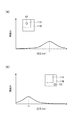
図1に示すような測定試料1を測定対象とした場合、赤色領域11Aの一部を照射範囲として照明光を照射すると、その照明光による反射光からは、例えば、図4(a)に示すような、600nm〜670nmの赤色波長域にピーク波長λ1を有する分光スペクトルSp1を取得できる。また、青色領域11Bの一部を照射範囲として照明光を照射すると、その照明光による反射光からは、例えば、図4(b)に示すような、420nm〜480nmの波長域にピーク波長λ2を有する分光スペクトルSp2を取得できる。なお、図中における斜線部は分光スペクトルを取得した範囲を示している。
When the
ここで、単一の色領域の一部を照射範囲として得られた反射光から取得できる分光スペクトルの光強度は、照射範囲からの反射光に含まれる各波長成分の光量を表しており、照射範囲の面積に比例していると考えることができる。そこで、本発明においては、単一の色領域の一部を照射範囲として得られた反射光から取得した分光スペクトルに基づき単位面積当たりの分光スペクトルを算出し、その単位面積当たりの分光スペクトルに色領域11の領域面積を乗算して色領域11全体の分光スペクトルを算出することとしている。
Here, the light intensity of the spectral spectrum that can be obtained from the reflected light obtained by using a part of a single color region as the irradiation range represents the light amount of each wavelength component included in the reflected light from the irradiation range, and the irradiation It can be considered to be proportional to the area of the range. Therefore, in the present invention, a spectral spectrum per unit area is calculated based on a spectral spectrum obtained from reflected light obtained by using a part of a single color region as an irradiation range, and the spectral spectrum per unit area is color-coded. The spectral area of the
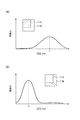
これにより、第1実施形態において、赤色領域11Aについては、図5(a)に示すような、ピーク波長λ1を有し、各波長成分の光強度の割合が分光スペクトルSp1と同様の分光スペクトルSp1´が演算値として算出され、青色領域11Bについては、図5(b)に示すような、ピーク波長λ2を有し、各波長成分の光強度の割合が分光スペクトルSp2と同様の分光スペクトルSP2´が演算値として算出される。
As a result, in the first embodiment, the
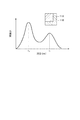
また、測定範囲S1全体の分光スペクトルは、その測定範囲S1を占める各色領域11全体の分光スペクトルの合計値であると考えることができるので、本発明においては、複数の色領域11全体の分光スペクトルを加算することにより、その測定範囲S1全体の分光スペクトルを演算値として算出することとしている。これにより、第1実施形態において、図6に示すような、ピーク波長λ1、λ2を有する分光スペクトルSp3が演算値として算出され、測定範囲S1全体の分光スペクトルが得られることになる。
Further, since the spectral spectrum of the entire measurement range S1 can be considered as the total value of the spectral spectra of the
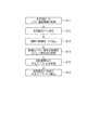
次に、上述の顕微分光測定装置3を用いて測定範囲S1の分光スペクトルを測定するための顕微分光測定方法について説明する。なお、以降の各ステップは、第1実施形態において、中央制御装置61のCPU62による制御の下で行われる。
Next, a microspectroscopic light measurement method for measuring the spectroscopic spectrum in the measurement range S1 using the microspectroscopic
まず、ステップS11においては、図1に示すように、測定試料1を撮像することにより、測定範囲S1を含む範囲を撮像範囲S2として、その撮像範囲S2内のカラー画像情報を取得する。
First, in step S11, as shown in FIG. 1, by imaging the
次に、ステップS12においては、ステップS11において取得した画像を中央制御装置61の表示部66に表示し、その表示された撮像範囲内の画像から測定範囲を設定する。測定範囲の設定は、例えば、撮像範囲を撮像した画像をユーザが中央制御装置61の表示部66で確認しながら、その表示部66の画像に表示されたポインタを操作部65により操作等することにより行われる。
Next, in step S12, the image acquired in step S11 is displayed on the
次に、ステップS13においては、ステップS11において取得したカラー画像情報を画像処理することにより、ステップS12において設定された測定範囲S1から複数の色領域11を抽出する。複数の色領域11を抽出する処理は、例えば、下記のような手順に沿って行われる。
Next, in step S13, the color image information acquired in step S11 is subjected to image processing, thereby extracting a plurality of
まず、サブステップS21においては、得られた画像情報についてノイズ除去のために平滑化処理等の前処理を行なう。 First, in sub-step S21, preprocessing such as smoothing processing is performed on the obtained image information to remove noise.
続いて、サブステップS22においては、RGB値等の色情報により表現されるカラー画像を、公知のアルゴリズムにより輝度値、色度値等の濃淡値により表現されるグレースケール画像に変換する処理を行なう。この処理は、例えば、各画素のRGB値からNTSC係数による加重平均法により輝度値を表す重み付け平均値を算出して、その算出値を各画素の輝度値とする処理が挙げられる。 Subsequently, in sub-step S22, a process of converting a color image expressed by color information such as RGB values into a gray scale image expressed by gray values such as luminance values and chromaticity values by a known algorithm is performed. . This process includes, for example, a process of calculating a weighted average value representing a luminance value from the RGB value of each pixel by a weighted average method using an NTSC coefficient and using the calculated value as the luminance value of each pixel.
続いて、サブステップS23においては、公知のアルゴリズムによりグレースケール画像のエッジを抽出する処理を行なう。このエッジ抽出処理は、例えば、Sobel、Prewitt等の一次微分フィルタ、Laplacian等の二次微分フィルタを用いた処理が挙げられる。 Subsequently, in sub-step S23, processing for extracting an edge of the grayscale image is performed by a known algorithm. Examples of the edge extraction processing include processing using a primary differential filter such as Sobel and Prewitt, and a secondary differential filter such as Laplacian.
続いて、サブステップS24においては、公知のアルゴリズムによりエッジの抽出されたエッジ抽出画像を二値化する処理を行なう。二値化処理を行なうことにより、エッジ抽出画像のエッジのみ、即ち、複数の色領域の輪郭線のみが描かれた二値化画像を取得する。この二値化処理で用いられるアルゴリズムとしては、例えば、二値化するための閾値を自動的に算出することが可能な大津の方法が挙げられる。 Subsequently, in sub-step S24, a process of binarizing the edge extracted image from which the edge is extracted by a known algorithm is performed. By performing binarization processing, a binarized image in which only the edges of the edge extracted image, that is, only the outlines of a plurality of color regions are drawn, is acquired. As an algorithm used in this binarization processing, for example, Otsu's method capable of automatically calculating a threshold for binarization can be cited.
以上により、撮像された画像情報から測定範囲S1から複数の色領域11が抽出される。なお、ステップS11において取得したカラー画像情報を画像処理することにより複数の色領域11を抽出するためのアルゴリズムは、上述の方法に限定されない。
As described above, the plurality of
また、上述のステップS13においては、ステップS11において取得したカラー画像情報を画像処理することにより、抽出した複数の色領域11の領域面積を算出しておく。ここでいう領域面積とは、測定範囲S1内において複数の色領域11それぞれが占める面積のことをいう。領域面積は、例えば、上述のサブステップS24において取得した二値化画像における複数の色領域11の輪郭線内の画素数に基づき算出される。
In step S13 described above, the color image information acquired in step S11 is subjected to image processing to calculate the area areas of the extracted
次に、ステップS14においては、ステップS13において抽出した色領域11の一部を照射範囲S2として照明光学系29により照明光を照射する。このステップS14は、照明光学系29による照明光の照射範囲S2を視野絞り33により拡大又は縮小するとともに、二次光源となる光ファイバ31の出射端31aと視野絞り33とを光軸と直交する方向に移動させることによって、色領域11の範囲内に照射範囲S2が収まるように範囲調整及び位置調整するステップが含まれる。このように、ステップS13において画像処理により色領域11を抽出しているので、このステップS14において複数の色領域11のうちの単一の色領域11のみが照射範囲S2となるように容易に調整できる。
Next, in step S14, the illumination
次に、ステップS15においては、ステップS14において照射範囲S2に照射した照明光による反射光により、その照射範囲S2、即ち、色領域11の一部の分光スペクトルを分光器51により取得する。これらステップS14、ステップS15により、照明光を照射している単一の色領域11の分光スペクトルのみが取得できる。
Next, in step S15, the
ステップS14及びステップS15は、測定範囲S1内の複数の色領域11それぞれの一部の分光スペクトルを取得するまで繰り返し行う。
Steps S14 and S15 are repeated until partial spectral spectra of each of the plurality of
次に、ステップS16においては、複数の色領域11それぞれに対応した領域面積及び分光スペクトルに基づいて、その測定範囲S1全体の分光スペクトルを算出する。
Next, in step S <b> 16, the spectrum of the entire measurement range S <b> 1 is calculated based on the area and spectrum corresponding to each of the plurality of
具体的には、まず、ステップS15において取得した単一の色領域11の一部の分光スペクトルに基づき、その色領域11の単位面積当たりの分光スペクトルを演算値として算出する。単位面積当たりの分光スペクトルは、ステップS14において調整して得られた照明光学系29による照射範囲S2の面積により色領域11の一部の分光スペクトルの各波長成分毎の光強度を除算して算出する。
Specifically, first, based on a part of the spectral spectrum of the
続いて、色領域11の単位面積当たりの分光スペクトルとその色領域11の領域面積を乗算して色領域11全体の分光スペクトルを演算値として算出する。色領域11全体の分光スペクトルは、色領域11の単位面積当たりの分光スペクトルの各波長成分毎の光強度とその色領域11の領域面積を乗算して算出する。
Subsequently, the spectral spectrum per unit area of the
続いて、測定範囲S1を占める各色領域11全体の分光スペクトルを加算して、その測定範囲S1全体の分光スペクトルを演算値として算出する。測定範囲S1全体の分光スペクトルは、複数の色領域11全体の分光スペクトルの各波長成分毎の光強度を加算して算出する。
Subsequently, the spectral spectra of the
なお、ステップS16において算出された測定範囲S1全体の分光スペクトルは、例えば、中央制御装置61の表示部66に表示されたり、中央制御装置61のROM64に記憶される。
Note that the spectral spectrum of the entire measurement range S1 calculated in step S16 is displayed on, for example, the
以上によれば、視野絞りの開口形状による制限を受けることなく様々な形状を測定範囲S1としてその測定範囲の分光スペクトルを測定することが可能となる。また、測定範囲S1の分光スペクトルを測定するうえで、測定範囲S1から複数の色領域を画像処理することにより抽出し、その抽出した複数の色領域それぞれの一部について分光スペクトルを取得した後に演算処理を行うのみで足りるため、測定範囲S1内の測定を短時間で完了させることが可能となる。 According to the above, it is possible to measure the spectrum of the measurement range with various shapes as the measurement range S1 without being restricted by the aperture shape of the field stop. Further, when measuring the spectral spectrum of the measurement range S1, a plurality of color regions are extracted from the measurement range S1 by image processing, and calculation is performed after obtaining spectral spectra for a part of each of the extracted color regions. Since it is sufficient to perform the processing, the measurement within the measurement range S1 can be completed in a short time.
以上、本発明の実施形態の例について詳細に説明したが、前述した実施形態は、何れも本発明を実施するにあたっての具体化の例を示したものに過ぎず、これらによって本発明の技術的範囲が限定的に解釈されてはならないものである。 As mentioned above, although the example of embodiment of this invention was demonstrated in detail, all the embodiment mentioned above showed only the example of actualization in implementing this invention, and these are the technical aspects of this invention. The range should not be construed as limiting.
例えば、上述の実施形態においては、分光器51により照明光による反射光の分光スペクトルを取得するものとして説明したが、分光器51により照明光による透過光の分光スペクトルを取得するものから構成されていてもよい。
For example, in the above-described embodiment, the
1 :測定試料
3 :顕微分光測定装置
11 :色領域
20 :ステージ
29 :照明光学系
41 :撮像装置
43 :撮像素子
51 :分光器
61 :中央制御装置
S1 :測定範囲
S2 :照射範囲
1: Measurement sample 3: Microspectroscopic light measurement device 11: Color region 20: Stage 29: Illumination optical system 41: Imaging device 43: Imaging device 51: Spectroscope 61: Central control device S1: Measurement range S2: Irradiation range
Claims (5)
前記測定試料を撮像して前記測定範囲を含む撮像範囲のカラー画像情報を取得する撮像手段と、
前記カラー画像情報を画像処理することにより、前記測定範囲から色に応じて区分けされる複数の色領域を抽出するとともに、前記複数の色領域の領域面積を算出する画像処理手段と、
前記画像処理手段により抽出された色領域の一部を照射範囲として照明光を照射する照明光学系と、
前記照射範囲に照射された照明光による反射光又は透過光により前記色領域の一部の分光スペクトルを取得する分光スペクトル取得手段と、
前記色領域の領域面積と、前記色領域の一部の分光スペクトルとに基づき演算処理を行なう演算処理手段とを備え、
前記照明光学系及び前記分光スペクトル取得手段により前記複数の色領域それぞれの一部の分光スペクトルを取得し、
前記演算処理手段は、前記複数の色領域それぞれに対応した領域面積及び一部の分光スペクトルに基づいて、前記測定範囲全体の分光スペクトルを算出すること
を特徴とする顕微分光測定装置。 In a microspectrophotometer for measuring a part of a measurement sample as a measurement range and measuring a spectrum of the measurement range,
Imaging means for imaging the measurement sample and obtaining color image information of an imaging range including the measurement range;
An image processing unit that extracts a plurality of color regions classified according to color from the measurement range by performing image processing on the color image information, and calculates a region area of the plurality of color regions;
An illumination optical system for illuminating illumination light with a part of the color region extracted by the image processing means as an illumination range;
Spectral spectrum acquisition means for acquiring a spectral spectrum of a part of the color region by reflected light or transmitted light by illumination light irradiated on the irradiation range;
Arithmetic processing means for performing arithmetic processing based on the area of the color region and a part of the spectral spectrum of the color region,
Obtaining a partial spectrum of each of the plurality of color regions by the illumination optical system and the spectral spectrum acquisition means,
The arithmetic processing unit calculates a spectral spectrum of the entire measurement range based on a region area corresponding to each of the plurality of color regions and a partial spectral spectrum.
を特徴とする請求項1記載の顕微分光測定装置。 The arithmetic processing means calculates a spectral spectrum per unit area of the color area based on a part of the spectral spectrum of the color area acquired by the spectral spectrum means, and calculates the spectral per unit area of the calculated color area. The spectral spectrum of the entire color area is calculated by multiplying the spectrum and the area of the color area, and the spectral spectrum of the entire color area of each of the plurality of color areas is added to calculate the spectral spectrum of the entire measurement range. The microspectroscopic light measuring apparatus according to claim 1, wherein:
を特徴とする請求項1又は2記載の顕微分光測定装置。 The microspectroscopic measurement apparatus according to claim 1, further comprising setting means for setting the measurement range.
前記照明範囲調整手段は、前記画像処理手段により抽出された色領域に基づき、その色領域の一部に照明光が照射されるように前記照射範囲を範囲調整及び位置調整すること
を特徴とする請求項1〜3の何れか1項記載の顕微分光測定装置。 An irradiation range adjusting means for adjusting the range and position of the irradiation range of the illumination light irradiated from the illumination optical system to the measurement sample;
The illumination range adjustment unit is configured to perform range adjustment and position adjustment of the illumination range based on the color region extracted by the image processing unit so that illumination light is irradiated to a part of the color region. The microspectrophotometer according to any one of claims 1 to 3.
前記照明範囲調整手段は、前記照明光の光軸と直交する方向に一体的に移動可能な前記光源と前記視野絞りとから構成されていること
を特徴とする請求項4記載の顕微分光測定装置。 The illumination optical system includes a light source that emits the illumination light, and a field stop that adjusts an irradiation range on the measurement surface of the measurement sample of the illumination light emitted from the light source,
The microscopic light measurement apparatus according to claim 4, wherein the illumination range adjustment unit includes the light source and the field stop that are integrally movable in a direction orthogonal to the optical axis of the illumination light. .
Priority Applications (1)
| Application Number | Priority Date | Filing Date | Title |
|---|---|---|---|
| JP2011050884A JP2012189342A (en) | 2011-03-08 | 2011-03-08 | Microspectrometry apparatus |
Applications Claiming Priority (1)
| Application Number | Priority Date | Filing Date | Title |
|---|---|---|---|
| JP2011050884A JP2012189342A (en) | 2011-03-08 | 2011-03-08 | Microspectrometry apparatus |
Publications (1)
| Publication Number | Publication Date |
|---|---|
| JP2012189342A true JP2012189342A (en) | 2012-10-04 |
Family
ID=47082704
Family Applications (1)
| Application Number | Title | Priority Date | Filing Date |
|---|---|---|---|
| JP2011050884A Withdrawn JP2012189342A (en) | 2011-03-08 | 2011-03-08 | Microspectrometry apparatus |
Country Status (1)
| Country | Link |
|---|---|
| JP (1) | JP2012189342A (en) |
Cited By (4)
| Publication number | Priority date | Publication date | Assignee | Title |
|---|---|---|---|---|
| DE102014113188A1 (en) | 2014-09-12 | 2016-03-17 | Carl Zeiss Microscopy Gmbh | Digital microscope and method for its commissioning |
| CN107314978A (en) * | 2017-07-28 | 2017-11-03 | 浙江大学 | Microcell visible spectrophotometer and spectral measurement method |
| WO2019142699A1 (en) * | 2018-01-16 | 2019-07-25 | 株式会社ニコン | Spectral diffraction data management device, measurement device, and measurement system |
| CN111928943A (en) * | 2020-08-19 | 2020-11-13 | 天津大学 | System and method for spectral measurement of depth of single high aspect ratio micropore |
-
2011
- 2011-03-08 JP JP2011050884A patent/JP2012189342A/en not_active Withdrawn
Cited By (7)
| Publication number | Priority date | Publication date | Assignee | Title |
|---|---|---|---|---|
| DE102014113188A1 (en) | 2014-09-12 | 2016-03-17 | Carl Zeiss Microscopy Gmbh | Digital microscope and method for its commissioning |
| CN105425376A (en) * | 2014-09-12 | 2016-03-23 | 卡尔蔡司显微镜有限责任公司 | Digital microscope and method of commissioning |
| DE102014113188B4 (en) | 2014-09-12 | 2024-01-04 | Carl Zeiss Microscopy Gmbh | Digital microscope and method for putting it into operation |
| CN107314978A (en) * | 2017-07-28 | 2017-11-03 | 浙江大学 | Microcell visible spectrophotometer and spectral measurement method |
| WO2019142699A1 (en) * | 2018-01-16 | 2019-07-25 | 株式会社ニコン | Spectral diffraction data management device, measurement device, and measurement system |
| JPWO2019142699A1 (en) * | 2018-01-16 | 2020-12-10 | 株式会社ニコン | Spectroscopic data management equipment, measuring equipment and measuring system |
| CN111928943A (en) * | 2020-08-19 | 2020-11-13 | 天津大学 | System and method for spectral measurement of depth of single high aspect ratio micropore |
Similar Documents
| Publication | Publication Date | Title |
|---|---|---|
| US10605661B2 (en) | Image capturing with filters of overlapping passbands | |
| JP7424286B2 (en) | Fluorescence observation device and fluorescence observation method | |
| TWI509220B (en) | Surface topography interferometer with surface color | |
| US7454046B2 (en) | Method and system for analyzing skin conditions using digital images | |
| JP6322939B2 (en) | Imaging system and color inspection system | |
| JP5806504B2 (en) | Imaging apparatus and microscope system including the same | |
| KR101284268B1 (en) | Color lighting control method for improving image quality of vision system | |
| US20090042179A1 (en) | Fluorescence Reflection Imaging Device with Two Wavelengths | |
| JP2008268387A (en) | Confocal microscope | |
| CN108692815B (en) | Multispectral imaging using longitudinal chromatic aberration | |
| JP6605716B2 (en) | Automatic staining detection in pathological bright field images | |
| WO2015111349A1 (en) | Multicolor-fluorescence-image analysis device | |
| JP6068375B2 (en) | Spectral radiance meter | |
| JP2012189342A (en) | Microspectrometry apparatus | |
| US20130286396A1 (en) | Inspection device | |
| WO2010066951A1 (en) | Method and device for imaging a target | |
| JPWO2017141291A1 (en) | Imaging apparatus and image processing method | |
| JP2013003386A (en) | Image pickup apparatus and virtual slide device | |
| JP5246798B2 (en) | Biological tissue identification apparatus and method | |
| JP6609967B2 (en) | Determination device, determination system, determination program, and cell manufacturing method | |
| JP5062588B2 (en) | Microscope imaging apparatus and method | |
| WO2018128146A1 (en) | Spectral measurement method and spectral measurement device | |
| JP5408527B2 (en) | Creating a melanoma diagnostic image | |
| JP7136064B2 (en) | Apparatus for inspecting surface of object to be inspected and method for inspecting surface of object to be inspected | |
| EP4118417A1 (en) | High throughput snapshot spectral encoding device for fluorescence spectral microscopy |
Legal Events
| Date | Code | Title | Description |
|---|---|---|---|
| RD04 | Notification of resignation of power of attorney |
Free format text: JAPANESE INTERMEDIATE CODE: A7424 Effective date: 20120830 |
|
| RD04 | Notification of resignation of power of attorney |
Free format text: JAPANESE INTERMEDIATE CODE: A7424 Effective date: 20120905 |
|
| A300 | Withdrawal of application because of no request for examination |
Free format text: JAPANESE INTERMEDIATE CODE: A300 Effective date: 20140513 |