JP2012189324A - Stereo camera - Google Patents
Stereo camera Download PDFInfo
- Publication number
- JP2012189324A JP2012189324A JP2011050508A JP2011050508A JP2012189324A JP 2012189324 A JP2012189324 A JP 2012189324A JP 2011050508 A JP2011050508 A JP 2011050508A JP 2011050508 A JP2011050508 A JP 2011050508A JP 2012189324 A JP2012189324 A JP 2012189324A
- Authority
- JP
- Japan
- Prior art keywords
- camera
- monocular camera
- monocular
- image
- cameras
- Prior art date
- Legal status (The legal status is an assumption and is not a legal conclusion. Google has not performed a legal analysis and makes no representation as to the accuracy of the status listed.)
- Withdrawn
Links
Images


Abstract
Description
本発明は、2つの単眼カメラを並設したステレオカメラに関するものである。 The present invention relates to a stereo camera in which two monocular cameras are arranged side by side.
近年、環境認識へのニーズが高まっており、たとえば自動車にステレオカメラを搭載し、運転者に周囲の歩行者の有無などの情報を提供し、運転支援をするシステムが実用化されつつある。このようなステレオカメラは複数の位置に設置された単眼カメラからの画像を取得し、視差(各画像における像位置の差)を用いて物体の距離や位置を測定する装置である。上記ステレオカメラでは単眼カメラ間の相対位置を用いて距離を算出しているため、単眼カメラ間の相対位置の位置決め精度、または単眼カメラ間の相対位置の検出精度が重要となる。車両に搭載されるようなステレオカメラの場合、経時変化による位置ずれに関しては、特別な装置を用いないキャリブレーション方法が必要とされる。 In recent years, needs for environmental recognition are increasing. For example, a system that supports driving by providing a vehicle with a stereo camera and providing information such as the presence or absence of a pedestrian to the driver is being put into practical use. Such a stereo camera is an apparatus that acquires images from monocular cameras installed at a plurality of positions and measures the distance and position of an object using parallax (difference in image positions in each image). In the stereo camera, since the distance is calculated using the relative position between the monocular cameras, the positioning accuracy of the relative position between the monocular cameras or the detection accuracy of the relative position between the monocular cameras is important. In the case of a stereo camera that is mounted on a vehicle, a calibration method that does not use a special device is required for a positional shift due to a change with time.
特許文献1には、各カメラの画像の特徴点の座標を推定し、各単眼カメラで共通する特徴点の推定座標を用いて単眼カメラ間における相対位置を推定している3次元画像取得装置が開示されている。この特許文献1は、ステレオカメラにおいてカメラの相対位置ずれを校正する目的で、画像上の特徴点の3次元座標の推定結果から、ステレオカメラの相対位置を算出している。 Patent Document 1 discloses a three-dimensional image acquisition apparatus that estimates the coordinates of feature points of an image of each camera and estimates the relative position between the monocular cameras using estimated coordinates of feature points common to the monocular cameras. It is disclosed. This patent document 1 calculates the relative position of the stereo camera from the estimation result of the three-dimensional coordinates of the feature points on the image for the purpose of calibrating the relative position shift of the camera in the stereo camera.
しかしながら、上記に示されるような特許文献1に装置にあっては、距離測定精度に対する、経時変化による単眼カメラ間の相対位置ずれの影響を小さくするものの、単眼カメラ間の相対位置を推定することに用いる特徴点の座標自体も推定値であるため、高精度にキャリブレーションを行うことは難しい上に、負荷の高い計算をする必要がある。すなわち、推定の難しい光軸の傾きも補正するために画像の推定によってのみ補正されるため計算負荷が高いという問題点があった。 However, in the apparatus disclosed in Patent Document 1 as described above, the relative position between monocular cameras is estimated while the influence of the relative position shift between monocular cameras due to the change over time on the distance measurement accuracy is reduced. Since the coordinates of the feature points used in the above are also estimated values, it is difficult to perform calibration with high accuracy, and it is necessary to perform calculation with a high load. That is, there is a problem that the calculation load is high because the inclination of the optical axis, which is difficult to estimate, is corrected only by image estimation.
本発明は、上記に鑑みてなされたものであって、撮影画像から検出することが困難なカメラ光軸の傾きのずれを抑えることで、経時変化が距離測定精度に及ぼす影響を低減できるステレオカメラを提供することを目的とする。 The present invention has been made in view of the above, and is a stereo camera that can reduce the influence of changes over time on distance measurement accuracy by suppressing the deviation of the tilt of the camera optical axis that is difficult to detect from a captured image. The purpose is to provide.
上述した課題を解決し、目的を達成するために、本発明は、第1の単眼カメラと第2の単眼カメラとを一体に並設したステレオカメラであって、前記第1の単眼カメラおよび前記第2の単眼カメラは、光軸に直交する基準面を有し、前記第1の単眼カメラおよび前記第2の単眼カメラの前記基準面に当接させるとともに、この2つのカメラの光軸が同一直線上になる位置に並設させて連結する連結部材と、前記連結部材に取り付けられた前記第1の単眼カメラと前記第2の単眼カメラからの撮影画像を補正する画像補正手段と、前記画像補正手段で補正された補正画像から視差を求め、被写体の距離を算出する距離算出手段と、を備えることを特徴とする。 In order to solve the above-described problems and achieve the object, the present invention is a stereo camera in which a first monocular camera and a second monocular camera are integrally arranged, and includes the first monocular camera and the monocular camera. The second monocular camera has a reference plane orthogonal to the optical axis and is brought into contact with the reference planes of the first monocular camera and the second monocular camera, and the optical axes of the two cameras are the same. A connecting member that is connected in parallel at a position on a straight line, an image correcting unit that corrects a captured image from the first monocular camera and the second monocular camera attached to the connecting member, and the image Distance calculating means for obtaining parallax from the corrected image corrected by the correcting means and calculating the distance of the subject.
本発明は、連結部材に第1の単眼カメラおよび第2の単眼カメラの基準面に当接させるとともに、この2つのカメラの光軸が同一直線上になる位置に並設させて連結することにより、2つの単眼カメラの光軸に直交する面を取り付け基準面としているので、撮影画像から推定することが難しい光軸の傾きズレの発生を抑制し、推定が困難な光軸の傾きが小さいことによって経時変化が距離測定精度に及ぼす影響を少なくすることができるという効果を奏する。 According to the present invention, the connecting member is brought into contact with the reference planes of the first monocular camera and the second monocular camera, and the optical axes of the two cameras are arranged in parallel at a position where they are on the same straight line. Because the plane perpendicular to the optical axis of the two monocular cameras is used as the mounting reference plane, the tilt of the optical axis that is difficult to estimate from the captured image is suppressed, and the tilt of the optical axis that is difficult to estimate is small. As a result, the influence of the change over time on the distance measurement accuracy can be reduced.
以下に添付図面を参照して、この発明にかかるステレオカメラの一実施の形態を詳細に説明する。 Hereinafter, an embodiment of a stereo camera according to the present invention will be described in detail with reference to the accompanying drawings.
(実施の形態)
本発明は、複数のカメラを備え、各カメラからの撮像における像位置の差から物体の距離を測定するステレオカメラにおいて、画像から推定することが困難な光軸の傾きを抑えることのできるように単眼カメラの光軸がカメラステイへの取り付け基準面に直交する面となっていることが特徴である。以下、具体的に説明する。
(Embodiment)
In a stereo camera that includes a plurality of cameras and measures the distance of an object from a difference in image position in imaging from each camera, the tilt of the optical axis that is difficult to estimate from an image can be suppressed. The feature is that the optical axis of the monocular camera is a plane orthogonal to the reference plane for attachment to the camera stay. This will be specifically described below.
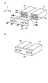
図1は、この実施の形態におけるステレオカメラの構成を示す説明図である。この図1(A)は2つの単眼カメラ、この2つのカメラを連結するカメラステイそれぞれの単体形状を示し、(B)は組み付け後のステレオカメラの状態を示している。この図1において、符号100は第1の単眼カメラ、符号110は第2の単眼カメラ、符号120は連結部材としてのカメラステイである。このように、ステレオカメラは、第1の単眼カメラ100と第2の単眼カメラ110の2つの単眼カメラ、この2つの単眼カメラを取り付けるカメラステイ120を有する。
FIG. 1 is an explanatory diagram showing the configuration of the stereo camera in this embodiment. FIG. 1A shows a single shape of each of two monocular cameras and a camera stay connecting the two cameras, and FIG. 1B shows a state of the stereo camera after assembly. In FIG. 1,
第1の単眼カメラ100および第2の単眼カメラ110は、レンズなどの光学系、たとえばCCDといった撮像素子などを有して対象物を撮影し、デジタル画像データを取得し、この撮影画像データに対して、後述する画像処理部(図5参照)で所定の画像処理が実行される。
The first
また、符号100a,110aは、上記2つのカメラの光軸に対して直角の平面を有するカメラ基準面、符号100b,110bは、上記2つの単眼カメラがカメラステイ120に取り付けられる際に光軸のY方向の位置決めが可能な係合孔である。また、符号130は、カメラステイ120と上記2つの単眼カメラとを位置きめしながらねじ締結が可能なねじ固定ピンである。ここで、係合孔100b,110bの内径寸法とねじ固定ピン130の根元部分の外径は同一寸法で所定の嵌め合い公差で設計されている。このように、ねじ固定ピン130の根元部分が各カメラの係合孔100b,110bと嵌合して位置がずれないように所定の寸法精度の形状を有する。このように構成された2つの単眼カメラの筐体前面をカメラステイ120への取り付け面とした上でねじ固定ピン130と係合孔100b,110bで基準面内での位置決めを行って固定する。
カメラステイ120は、経時変化や温度変化に影響を受けにくい、ある程度の剛性を有する材料を素材としている。カメラステイ120は、カメラ基準面100a,110aに接触する面が、カメラ基準面100a,110aに接触して固定されても、上記光軸がずれないにように、また、一定の平面度を有している。カメラステイ120のカメラ取り付け面は、たとえば切削あるいは成型により加工される。このようなカメラステイ120の形状とすることで、加工が容易となるとともに、構成が簡単なため組み立て時の積み上げ公差を小さくすることができ、組み立て時の精度を確保することができる。
The
このカメラステイ120には、2つのカメラそれぞれのカメラ基準面100a,110aに接触する平面、あるいは部分的に接触するような面が形成されている。このカメラステイ120の面にカメラ基準面100a,110aを当接させた状態でねじ固定ピン130により連結して固定する。
The
この図1に示すように、最も簡易で実用的なステレオカメラの構成としてはX軸、もしくはY軸方向に基線長Bだけ離れて、平行に置かれた2つのカメラ、すなわち、カメラステイ120に位置決めされて固定された第1の単眼カメラ100と第2の単眼カメラ110からなる。
As shown in FIG. 1, the simplest and most practical stereo camera configuration includes two cameras placed in parallel, separated by a base line length B in the X-axis or Y-axis direction, that is, a camera stay 120. The first
初期の第1の単眼カメラ100と第2の単眼カメラ110の相対位置は、組み付け時に位置関係が既知となっているターゲットの測定をするなどの公知の方法で校正が行われているが、初期状態からのずれ量を補正する必要がある。
The initial relative positions of the first
上述したように、第1の単眼カメラ100と第2の単眼カメラ110は、光軸に直交する筐体前面をカメラ基準面100a,110aとして組みつけられている。第1の単眼カメラ100と第2の単眼カメラ110は、筐体前面を取り付け面として、カメラステイ120にねじ固定ピン130で引きこまれて組みつけられている。そのため、各単眼カメラの光軸がカメラステイ120に対して傾くのを防ぐことができる。また、Z方向に対してもカメラステイ120の同一面に当てられるため、カメラステイ120に対してZ方向の並進ずれも防ぐことができる。
As described above, the first
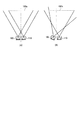
図2は、図1に示したカメラステイ120により2つの単眼カメラを組み立てて撮影される画像例を示す説明図である。この図2のX,Y,Z軸に示すように、X方向は2つのカメラが並設される方向、Y方向はX方向に対して直交する上下方向(光軸に対して直交する上下方向)であり、Z方向は撮影画面の光軸方向(図2の紙面と直交する被写体方向)である。なお、この図2では、第1の単眼カメラ100をカメラ1としてその撮影画像を実線、第2の単眼カメラ110をカメラ2として破線でそれぞれ図示している。図3は、2つの単眼カメラによる距離測定有効領域の様子を示す説明図である。この図3において(A)は上述したカメラステイ120により2つの単眼カメラを組み立てて撮影して得られる距離測定有効領域150a、(B)は2つの単眼カメラが傾いて組み立てられ、撮影して得られる距離測定有効領域150bについて示している。
FIG. 2 is an explanatory view showing an example of an image captured by assembling two monocular cameras by the
上述したようにカメラステイ120に取り付けられた第1の単眼カメラ100と第2の単眼カメラ110は、光軸の傾きずれが無視できるほど小さいときは、第1の単眼カメラ100と第2の単眼カメラ110間の相対位置がずれた際の像は図2に示すようになる。
As described above, when the first
また、図2においてZ方向のずれは撮影領域の面積から補正することができる。さらに、Y方向の並進ズレ、またZ軸まわりの回転ずれは、撮影画像の対応点の座標から補正することができる。なお、これらの補正処理は後述する画像処理部(図5参照)で行われる。 In FIG. 2, the deviation in the Z direction can be corrected from the area of the imaging region. Furthermore, translational displacement in the Y direction and rotational deviation about the Z axis can be corrected from the coordinates of corresponding points in the captured image. These correction processes are performed by an image processing unit (see FIG. 5) described later.
また、図2において遠距離にある対象の距離測定を行う際には、光軸の傾きによって像位置が大きく変化してしまうため、光軸の傾きを抑えることで対応点探索を小さいエリアで行える。また、遠方において距離測定を行える距離測定有効領域(2つのカメラの画角の重複領域)が減少すること、および距離測定有効領域が左右どちらかに寄ることを防ぐことができる(図3参照)。 In addition, when measuring the distance of an object at a long distance in FIG. 2, the image position changes greatly due to the inclination of the optical axis, so that corresponding point search can be performed in a small area by suppressing the inclination of the optical axis. . In addition, it is possible to prevent the distance measurement effective area (the overlapping area of the angles of view of the two cameras) from being reduced and the distance measurement effective area from moving to the left or right (see FIG. 3). .
ところで、上述したカメラステイ120は平板の構成であったが、この構成以外に、たとえばカメラステイ120をL型のアングル形状として突き当て部に押し当てて基準面内での位置決めを行ってもよい。ステレオカメラは、単眼カメラの筐体前面をカメラステイへの取り付け面(カメラ基準面100a)とした上で、筐体前面と直交し、基線長方向と平行な面(図1のxz平面と平行な面)を第2の基準面としてもよい。この例を図4に示す。
By the way, although the
図4は、Lアングル状のカメラステイおよび単眼カメラの例を示す説明図である。この図4(A)は2つの単眼カメラ、この2つのカメラを連結するカメラステイそれぞれの単体形状を示し、(B)は組み付け後のステレオカメラの状態を示している。この図4に示すカメラステイ120は、第1の基準面120a、第2の基準面120bを有するLアングルの形状をなしている。第1の基準面120aと第2の基準面120bとは所定の精度を有した直角をなして形成する。また、このカメラステイ120の形状に突き当て可能に合致するように、第1の単眼カメラ100および第2の単眼カメラ110にも基準面100a,110aと直角にカメラ基準面100c,110cを形成する。なお、このカメラ基準面100c,110cは、カメラステイ120の第2の基準面120bと接触する部分のみ形成する。
FIG. 4 is an explanatory diagram illustrating an example of an L-angle camera stay and a monocular camera. FIG. 4A shows the single shapes of two monocular cameras and camera stays connecting the two cameras, and FIG. 4B shows the state of the stereo camera after assembly. The
図4に示す構成により、カメラステイ120に、第1の単眼カメラ100と第2の単眼カメラ110とを固定することにより、位置決めピン、または突き当て部によってカメラ間の調整をしなくてもカメラステイ120、2つの単眼カメラの基準面(100a,110a、100c,110c)の加工精度によって決まる。すなわち、図4に示す構成により、第2の基準面120bによって第1の単眼カメラ100と第2の単眼カメラ110間の光軸周りの回転ずれは、組み付け時に調整をしなくてもカメラステイ120、第1の単眼カメラ100および第2の単眼カメラ110の各カメラ基準面の加工精度によって決まる。
With the configuration shown in FIG. 4, the first
図4に示すLアングル状のカメラステイ120は、図1に示す平板のカメラステイ120よりも剛性に有利である。また、図4に示すLアングル状のカメラステイ120は、第1の基準面120aと第2の基準面120bを直角をなしてL型に設けてあるので、2つのカメラのカメラ基準面100a,110a、100c,110cをそのL型の面に当接することで組立性も向上する。
The L-angle camera stay 120 shown in FIG. 4 is more advantageous in rigidity than the
図5は、この実施の形態にかかるシステム構成を示すブロック図である。ここでは上述した図1あるいは図4に示すように、カメラステイ120の所定位置に固定された第1の単眼カメラ100、第2の単眼カメラ110(図では単にカメラと略記)、画像処理部160、距離演算部165、距離出力部170を備える。
FIG. 5 is a block diagram showing a system configuration according to this embodiment. Here, as shown in FIG. 1 or FIG. 4 described above, the first
この画像処理部160はマイクロコンピュータシステムで構成され、入出力インタフェース、CPU、ROM、RAM、外部記憶装置などを有する。上記ROMには、対象物を撮影して得られるデータにしたがって撮影画像を補正するなどの処理を行う画像処理プログラムが記憶されている。上記RAMはワーキングメモリとして用いられる。なお、図5では、画像処理部160、距離演算部165では、それぞれ別のブロックに分けているが、これらの機能を1つにまとめた構成であってもよい。
The
画像処理部160は、カメラステイ120に連結された第1の単眼カメラ100、第2の単眼カメラ110の内部パラメータや外部パラメータに従って、第1の単眼カメラ100、第2の単眼カメラ110より得られる撮影画像を補正する。距離演算部165は、画像処理部の出力する補正画像から視差を求めて、物体の距離を算出し、距離出力部170に送る。距離出力部170は、液晶モニタなどの表示装置を有し、距離演算部165から出力される測定距離に従って3D(3次元)マップを表示する。
The
以上説明したように、この実施の形態によれば、カメラステイ120に第1の単眼カメラ100および第2の単眼カメラ110の基準面に当接させるとともに、この2つのカメラの光軸が同一直線上になる位置に並設させて連結することにより、2つの単眼カメラの光軸に直交する面を取り付け基準面としているので、撮影画像から推定することが難しい光軸の傾きズレの発生を抑制し、推定が困難な光軸の傾きが小さいことによって経時変化が距離測定精度に及ぼす影響を少なくすることができる。
As described above, according to this embodiment, the
100 第1の単眼カメラ
100a,110a カメラ基準面
100b,110b 係合孔
100c,110c カメラ基準面
110 第2の単眼カメラ
120 カメラステイ
130 ねじ固定ピン
120a 第1基準面
120b 第2基準面
160 画像処理部
165 距離演算部
170 距離出力部
DESCRIPTION OF
Claims (4)
前記第1の単眼カメラおよび前記第2の単眼カメラは、光軸に直交する基準面を有し、
前記第1の単眼カメラおよび前記第2の単眼カメラの前記基準面に当接させるとともに、この2つのカメラの光軸が同一直線上になる位置に並設させて連結する連結部材と、
前記連結部材に取り付けられた前記第1の単眼カメラと前記第2の単眼カメラからの撮影画像を補正する画像補正手段と、
前記画像補正手段で補正された補正画像から視差を求め、被写体の距離を算出する距離算出手段と、
を備えることを特徴とするステレオカメラ。 A stereo camera in which a first monocular camera and a second monocular camera are integrally arranged,
The first monocular camera and the second monocular camera have a reference plane orthogonal to the optical axis,
A connecting member that is brought into contact with the reference plane of the first monocular camera and the second monocular camera and is connected in parallel at a position where the optical axes of the two cameras are on the same straight line;
Image correcting means for correcting captured images from the first monocular camera and the second monocular camera attached to the connecting member;
Distance calculating means for obtaining parallax from the corrected image corrected by the image correcting means and calculating the distance of the subject;
Stereo camera characterized by comprising.
前記第1の単眼カメラと前記第2の単眼カメラは、光軸と直交する第1の基準面と、前記第1の基準面と直交する第2の基準面を有し、
前記第1の基準面および前記第2の基準面と当接させ、この2つのカメラの光軸が同一直線上となる位置に並設させて連結する連結部材と、
前記連結部材に取り付けられた前記第1の単眼カメラと前記第2の単眼カメラからの撮影画像を補正する画像補正手段と、
前記画像補正手段で補正された補正画像から視差を求め、被写体の距離を算出する距離算出手段と、
を備えることを特徴とするステレオカメラ。 A stereo camera in which a first monocular camera and a second monocular camera are integrally arranged,
The first monocular camera and the second monocular camera have a first reference plane orthogonal to an optical axis and a second reference plane orthogonal to the first reference plane,
A connecting member that is brought into contact with the first reference surface and the second reference surface and connected in parallel at a position where the optical axes of the two cameras are on the same straight line;
Image correcting means for correcting captured images from the first monocular camera and the second monocular camera attached to the connecting member;
Distance calculating means for obtaining parallax from the corrected image corrected by the image correcting means and calculating the distance of the subject;
Stereo camera characterized by comprising.
Priority Applications (1)
| Application Number | Priority Date | Filing Date | Title |
|---|---|---|---|
| JP2011050508A JP2012189324A (en) | 2011-03-08 | 2011-03-08 | Stereo camera |
Applications Claiming Priority (1)
| Application Number | Priority Date | Filing Date | Title |
|---|---|---|---|
| JP2011050508A JP2012189324A (en) | 2011-03-08 | 2011-03-08 | Stereo camera |
Publications (1)
| Publication Number | Publication Date |
|---|---|
| JP2012189324A true JP2012189324A (en) | 2012-10-04 |
Family
ID=47082688
Family Applications (1)
| Application Number | Title | Priority Date | Filing Date |
|---|---|---|---|
| JP2011050508A Withdrawn JP2012189324A (en) | 2011-03-08 | 2011-03-08 | Stereo camera |
Country Status (1)
| Country | Link |
|---|---|
| JP (1) | JP2012189324A (en) |
Cited By (12)
| Publication number | Priority date | Publication date | Assignee | Title |
|---|---|---|---|---|
| CN103234514A (en) * | 2013-04-03 | 2013-08-07 | 广州市佳思信息科技有限公司 | Methods for distance measurement and offset measurement with single camera and for realizing naked eye 3D grating adjustment |
| JP2016031308A (en) * | 2014-07-29 | 2016-03-07 | 京セラ株式会社 | Image-capturing device, image-capturing system, and mobile entity |
| JP2017505903A (en) * | 2014-12-04 | 2017-02-23 | エスゼット ディージェイアイ テクノロジー カンパニー リミテッドSz Dji Technology Co.,Ltd | Imaging system and method |
| JP2017223669A (en) * | 2017-06-02 | 2017-12-21 | 日立オートモティブシステムズ株式会社 | Stereo vision system |
| US9854225B2 (en) | 2014-07-01 | 2017-12-26 | Ricoh Company, Ltd. | Imaging unit including a chassis and heat transfer member |
| US10214155B2 (en) | 2012-07-31 | 2019-02-26 | Hitachi Automotive Systems, Ltd. | On-vehicle image processing device |
| CN109803137A (en) * | 2017-11-16 | 2019-05-24 | 京瓷株式会社 | Bearing calibration and means for correcting |
| CN110053625A (en) * | 2018-01-19 | 2019-07-26 | 本田技研工业株式会社 | Apart from computing device and controller of vehicle |
| CN110191333A (en) * | 2019-06-04 | 2019-08-30 | 深圳市华芯技研科技有限公司 | A kind of more camera lens photometric stereo photographic devices of centralization |
| US10412274B2 (en) | 2015-03-18 | 2019-09-10 | Ricoh Company, Ltd. | Imaging unit, vehicle control unit and heat transfer method for imaging unit |
| US10800345B2 (en) | 2017-09-29 | 2020-10-13 | Denso Corporation | Vehicular camera apparatus |
| EP4064698A1 (en) | 2021-03-22 | 2022-09-28 | Ricoh Industrial Solutions Inc. | Stereo camera device |
-
2011
- 2011-03-08 JP JP2011050508A patent/JP2012189324A/en not_active Withdrawn
Cited By (19)
| Publication number | Priority date | Publication date | Assignee | Title |
|---|---|---|---|---|
| US10214155B2 (en) | 2012-07-31 | 2019-02-26 | Hitachi Automotive Systems, Ltd. | On-vehicle image processing device |
| US11225204B2 (en) | 2012-07-31 | 2022-01-18 | Hitachi Astemo, Ltd. | On-vehicle image processing device |
| US10589696B2 (en) | 2012-07-31 | 2020-03-17 | Hitachi Automotive Systems, Ltd. | On-vehicle image processing device |
| CN103234514B (en) * | 2013-04-03 | 2015-05-13 | 广州市佳思信息科技有限公司 | Methods for distance measurement and offset measurement with single camera and for realizing naked eye 3D grating adjustment |
| CN103234514A (en) * | 2013-04-03 | 2013-08-07 | 广州市佳思信息科技有限公司 | Methods for distance measurement and offset measurement with single camera and for realizing naked eye 3D grating adjustment |
| US9854225B2 (en) | 2014-07-01 | 2017-12-26 | Ricoh Company, Ltd. | Imaging unit including a chassis and heat transfer member |
| JP2016031308A (en) * | 2014-07-29 | 2016-03-07 | 京セラ株式会社 | Image-capturing device, image-capturing system, and mobile entity |
| JP2017505903A (en) * | 2014-12-04 | 2017-02-23 | エスゼット ディージェイアイ テクノロジー カンパニー リミテッドSz Dji Technology Co.,Ltd | Imaging system and method |
| US10728514B2 (en) | 2014-12-04 | 2020-07-28 | SZ DJI Technology Co., Ltd. | Imaging system and method |
| US10412274B2 (en) | 2015-03-18 | 2019-09-10 | Ricoh Company, Ltd. | Imaging unit, vehicle control unit and heat transfer method for imaging unit |
| JP2017223669A (en) * | 2017-06-02 | 2017-12-21 | 日立オートモティブシステムズ株式会社 | Stereo vision system |
| US10800345B2 (en) | 2017-09-29 | 2020-10-13 | Denso Corporation | Vehicular camera apparatus |
| CN109803137A (en) * | 2017-11-16 | 2019-05-24 | 京瓷株式会社 | Bearing calibration and means for correcting |
| CN110053625A (en) * | 2018-01-19 | 2019-07-26 | 本田技研工业株式会社 | Apart from computing device and controller of vehicle |
| CN110053625B (en) * | 2018-01-19 | 2022-03-11 | 本田技研工业株式会社 | Distance calculation device and vehicle control device |
| CN110191333A (en) * | 2019-06-04 | 2019-08-30 | 深圳市华芯技研科技有限公司 | A kind of more camera lens photometric stereo photographic devices of centralization |
| CN110191333B (en) * | 2019-06-04 | 2022-06-28 | 深圳市华芯技研科技有限公司 | Centralized multi-lens luminosity stereo camera device |
| EP4064698A1 (en) | 2021-03-22 | 2022-09-28 | Ricoh Industrial Solutions Inc. | Stereo camera device |
| US11805234B2 (en) | 2021-03-22 | 2023-10-31 | Ricoh Industrial Solutions Inc. | Stereo camera device |
Similar Documents
| Publication | Publication Date | Title |
|---|---|---|
| JP2012189324A (en) | Stereo camera | |
| KR101787304B1 (en) | Calibration method, calibration device, and computer program product | |
| TWI651578B (en) | Image capturing device | |
| JP5549230B2 (en) | Ranging device, ranging module, and imaging device using the same | |
| US20160264065A1 (en) | Vehicle-mounted camera, method of manufacturing vehicle-mounted camera, and method of manufacturing vehicle body | |
| US20200156560A1 (en) | On-Vehicle Image Processing Device | |
| US10209091B2 (en) | Measurement tool, calibration method, calibration apparatus, and computer-readable recording medium | |
| US10220783B2 (en) | Vehicle-mounted stereo camera device and method for correcting the same | |
| JP2012198075A (en) | Stereoscopic camera device and image adjusting method | |
| JP5293131B2 (en) | Compound eye distance measuring device for vehicle and compound eye distance measuring method | |
| JP2012167944A (en) | Stereo camera calibration method and device | |
| JP2011209269A (en) | Image pickup apparatus and range obtaining system | |
| JP2009068906A (en) | Distance measuring apparatus | |
| WO2014050282A1 (en) | Stereo camera device | |
| JP2007295113A (en) | Imaging apparatus | |
| JP5173551B2 (en) | Vehicle perimeter monitoring apparatus and camera mounting position / posture information setting correction method applied thereto | |
| JP2009053011A (en) | Imaging device | |
| JP2013050352A (en) | Method of adjusting installation of stereo camera, and stereo camera | |
| JP2009250785A (en) | Imaging device | |
| JP2008131176A (en) | Camera calibration device | |
| JP2007225403A (en) | Adjustment mechanism of distance measuring apparatus and stereoscopic shape recognition system provided with it | |
| JP2008241609A (en) | Distance measuring system and distance measuring method | |
| JP2016118400A (en) | Stereo camera device, moving body, control method, and calibration device | |
| JP6571571B2 (en) | Imaging apparatus, in-vehicle camera, and image processing method | |
| JP6985872B2 (en) | Vehicle peripheral monitoring device and peripheral monitoring method |
Legal Events
| Date | Code | Title | Description |
|---|---|---|---|
| A300 | Withdrawal of application because of no request for examination |
Free format text: JAPANESE INTERMEDIATE CODE: A300 Effective date: 20140513 |