JP2012187417A - Cooker - Google Patents
Cooker Download PDFInfo
- Publication number
- JP2012187417A JP2012187417A JP2012113150A JP2012113150A JP2012187417A JP 2012187417 A JP2012187417 A JP 2012187417A JP 2012113150 A JP2012113150 A JP 2012113150A JP 2012113150 A JP2012113150 A JP 2012113150A JP 2012187417 A JP2012187417 A JP 2012187417A
- Authority
- JP
- Japan
- Prior art keywords
- heater
- glass tube
- heating chamber
- heating
- heated
- Prior art date
- Legal status (The legal status is an assumption and is not a legal conclusion. Google has not performed a legal analysis and makes no representation as to the accuracy of the status listed.)
- Pending
Links
Images


Abstract
Description
本発明は、調理器本体内に被加熱物を収容する加熱調理器、とりわけ、誘導加熱調理器の下部に設けられるロースターに関連するものである。 The present invention relates to a cooking device that accommodates an object to be heated in a cooking device body, and more particularly to a roaster provided at a lower portion of an induction heating cooking device.
従来の加熱調理器においては、前記調理庫内と外気に通じる排気経路と、前記排気経路の途中に設置された触媒と、前記触媒に至る排気経路に設置され前記触媒を加熱する除煙ヒータ(以後、触媒ヒータとも呼ぶ)と、前記排気経路の前記触媒の下流側に配設される除煙ファンと、前記焼網の上部と下部に調理用ヒータを備え、調理開始時に前記除煙ヒータだけでなく前記上部調理用ヒータにも一定時間通電し、触媒が十分に性能を発揮できる温度に達した後前記下部調理用ヒータ、除煙ファンに通電する制御を行うことで、触媒の性能発揮可能な温度帯への到達速度を加速させるものがあった(例えば、特許文献1参照)。 In a conventional cooking device, an exhaust path leading to the inside of the cooking chamber and the outside air, a catalyst installed in the middle of the exhaust path, and a smoke removal heater installed in the exhaust path leading to the catalyst ( (Hereinafter also referred to as a catalyst heater), a smoke removal fan disposed on the exhaust path downstream of the catalyst, and a cooking heater on the upper and lower portions of the grill, and only the smoke removal heater at the start of cooking In addition, the upper cooking heater can be energized for a certain period of time, and after reaching a temperature at which the catalyst can fully perform, the lower cooking heater and smoke removal fan can be energized to control the performance of the catalyst. Some have accelerated the speed of reaching a certain temperature zone (see, for example, Patent Document 1).
特許文献1に示される従来の加熱調理器では背景技術の通り、加熱室内の脱煙を目的に、排気ダクトを設け、排気ダクト内に納められた脱煙脱臭触媒を加熱することによって、触媒の浄化性能を高めることにより、加熱室内の調理物から発生する煙や臭いを除去、抑制して排気していた。
In the conventional cooking device shown in
脱煙脱臭触媒には、白金やパラジウムなどが用いられており、その有効な脱煙、脱臭性能を発揮させるには、触媒の温度を300℃超に加熱する必要があり、加熱調理用とは別の触媒ヒータが設けられている。誘導加熱調理器向けロースターを例に取れば、出力で約300W程度のシーズヒータが取り付けられているのが一般的であり、通常、ロースターの調理中には排気ファンおよび触媒ヒータは通電しつづけるために、消費電力が大きいという課題がある。 Platinum, palladium, etc. are used for the deodorizing and deodorizing catalyst, and in order to exert its effective desmoking and deodorizing performance, it is necessary to heat the temperature of the catalyst to over 300 ° C. Another catalyst heater is provided. Taking a roaster for an induction heating cooker as an example, a sheathed heater with an output of about 300 W is generally attached. Normally, the exhaust fan and the catalyst heater continue to be energized during cooking of the roaster. In addition, there is a problem that power consumption is large.
また、従来の加熱調理器では焼網の上部と下部に調理用ヒータを備えているが、上部ヒータは加熱室天面の近くにシーズヒータなどを用いて設置されているために、結果的に被加熱物に対向する面と反対側に位置する加熱室の天面を加熱してしまう。加熱された天面は外部に放熱するか、周辺に組み込まれた部品の温度上昇に使われることとなり、熱ロスとなっていた。さらに、焼網下部に設けられているヒータは、加熱される食品から落下する油や食品カスが付着し、発火や発煙の要因となっていた。 In addition, conventional heating cookers have cooking heaters at the top and bottom of the grill, but the upper heater is installed near the top of the heating chamber using a sheathed heater, etc. The top surface of the heating chamber located on the opposite side to the surface facing the object to be heated is heated. The heated top surface radiates heat to the outside, or was used to increase the temperature of components built in the surrounding area, resulting in heat loss. Furthermore, the heater provided in the lower part of the grill has adhered to oil and food residue falling from the food to be heated, and has been a cause of fire and smoke.
本発明は、前記課題に鑑み為されたものであり、被加熱物を加熱するガラス管ヒータを保護することのできる加熱調理器を提供するものである。 This invention is made | formed in view of the said subject, and provides the heating cooker which can protect the glass tube heater which heats to-be-heated material.
本発明に係る加熱調理器は、加熱室と、前記加熱室に収容される受皿と、前記加熱室に設置され、被加熱物を加熱するガラス管ヒータと、前記受皿と前記ガラス管ヒータとの間に設置された赤外線透過材と、を備えたものである。 The heating cooker according to the present invention includes a heating chamber, a tray accommodated in the heating chamber, a glass tube heater that is installed in the heating chamber and heats an object to be heated, and the tray and the glass tube heater. And an infrared transmitting material installed between them.
本発明の加熱調理器によれば、加熱室に設置されたガラス管ヒータと受皿との間に赤外線透過材を設けたので、ガラス管ヒータが赤外線透過材を介して被加熱物を加熱し、ガラス管ヒータを保護することができる。 According to the cooking device of the present invention, since the infrared ray transmitting material is provided between the glass tube heater and the receiving tray installed in the heating chamber, the glass tube heater heats the object to be heated via the infrared ray transmitting material, The glass tube heater can be protected.
実施の形態1.
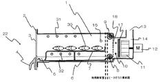
本発明を実施する形態として、図1、図2を用いて説明する。図1はこの発明を実施するための実施の形態における、加熱調理器の斜視図であり、図2は加熱調理器の加熱室主要部における断面図である。
An embodiment of the present invention will be described with reference to FIGS. FIG. 1 is a perspective view of a cooking device in an embodiment for carrying out the present invention, and FIG. 2 is a cross-sectional view of a main part of a heating chamber of the cooking device.
IHクッキングヒータ20は主に鍋・フライパン調理を行う誘導加熱部21と魚焼きなどを行うロースター22、および操作を実施する操作パネル23からなる。本発明はロースター22に関連するものであり、誘導加熱部21などの詳細な説明は割愛する。
The IH
図2はロースター22の主要部断面図である。加熱室1は金属製の筐体と扉2により構成され、扉2は視認窓3とその枠体で構成されるとともに、レール5に嵌合され、把手4を把持することにより、奥(図2中紙面右側)から手前までスムースに引き出し・収納可能な状態に構成されている。視認窓3からは加熱室1内の調理の様子が確認可能である。
FIG. 2 is a cross-sectional view of the main part of the
扉2の枠体には被加熱物30から垂れる油などを受けるための受皿6と被加熱物30を設置する焼網7が着脱可能な状態で設置されており、調理中の庫内汚れを防止するとともに、受皿6、焼網7ともとりはずして調理後の洗浄が行える状態となっている。
In the frame of the door 2, a tray 6 for receiving oil dripping from the
魚などを調理する場合、煙や臭いなどが発生するため、脱臭・排煙装置として、加熱室1の背面側の排気ダクト14内には脱臭触媒17が設置され、触媒ヒータ10により加熱されることで触媒効果を発揮させるとともに、ファンモータ12の駆動力により回転される排気ファン11により、排気口13を介して、本体奥面上部から煙を排出させる。排気口13は誘導加熱部21奥側に連通される形で設置され、排煙は通常、キッチン上部に設置されている換気扇やレンジフードファン(いずれも図示せず)により屋外へ排出される。
When cooking fish or the like, smoke and odor are generated, and therefore, a
本発明の根幹となる下ガラス管ヒータ8及び上ガラス管ヒータ9は、加熱室1の背面に設置され、かつ加熱室1の背面に設置されている排気ダクト14の開口部18の近傍に設置される。さらに詳細には、加熱室1の背面に設置されている排気ダクト14の開口部18の近傍且つ受皿6より上方かつ焼網7より下方の位置に配置されるか、あるいは加熱室1の背面に設置されている排気ダクト14の開口部18の近傍且つ焼網7より上方の位置に配置される。下ガラス管ヒータ8及び上ガラス管ヒータ9は、下ガラス管ヒータ8、上ガラス管ヒータ9の詳細に関しては後述するが、扉2に設置されている受皿6、焼網7を最深部まで収納した状態において、下ガラス管ヒータ8、上ガラス管ヒータ9のガラスにおける最前面と焼網7最背面の間にはスペースを設けて設置することで、万が一ガラスが割れた場合にも破片が被加熱物30に混入することなく加熱室1底部もしくは受皿6に落下するため、異物を口にしてしまう危険性はない。
The lower
下ガラス管ヒータ8、上ガラス管ヒータ9はそれぞれ加熱室1背面の略下端部、略上端部に設置され、焼網7上に載置された被加熱物30に向けて設置されることで、被加熱物30を輻射加熱するとともに、被加熱物30とは反対側に位置する排気ダクト14の開口部18を通して、脱煙脱臭触媒17も加熱する効果を有する。
The lower
下ガラス管ヒータ8、上ガラス管ヒータ9からの輻射熱による加熱でも十分に被加熱物30を加熱することは可能であるが、被加熱物30の設置場所による加熱不均一を是正して、被加熱物30の調理仕上がりを向上させたい場合には、加熱室1天面前部に設けた上シーズヒータ(天面ヒータを構成する)31、および扉2収納の際に、受皿6、焼網7に対して干渉しない位置に設けた下シーズヒータ(天面ヒータを構成する)32により、それぞれ補完的に加熱を実施する。
Although it is possible to sufficiently heat the object to be heated 30 even by heating by radiant heat from the lower
15は加熱室1内の温度を計測するための温度センサであり、サーミスタなどで構成される。調理により必要な加熱室1内の温度は異なるが、操作部23などの設定・入力に応じて設定温度に達した場合には各ヒータをOFF、加熱室1内温度が設定温度から任意の温度だけ下がったら再度各ヒータをONするなどの制御を行うことで、被加熱物30を仕上がりよく加熱することが可能となる。なお、領域を分割して温度を計測する場合には、加熱室1内の適当な位置に複眼赤外線センサを設置することで検知するように構成することが可能である。
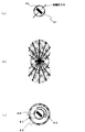
図3は本発明の実施の形態1における下ガラス管ヒータ8、上ガラス管ヒータ9の縦断面図である。 図3(a)に示すとおり、ガラス管ヒータは、純度99%以上のカーボンコンポジット材であるカーボンフィラメント40と、周辺を封止する石英ガラス製のガラス管41からなり、ガラス管41内はアルゴンなどの不活性ガスが封入されており、カーボンフィラメント40の酸化による劣化を防止している。
FIG. 3 is a longitudinal sectional view of the lower
図3(b)には同ヒータの輻射強度分布を示す。図中矢印の長さは輻射強度を示しており、カーボンフィラメント40を中心に、断面長方形の長辺に対して垂直な方向に強い輻射分布を示す八の字状の分布となる。図3(b)の通り、カーボンフィラメント40は、断面が長方形にカットされており、かつ略全面から発熱することから、相対的には長方形の長辺に対して垂直方向に強い輻射分布を持つ。
FIG. 3B shows the radiation intensity distribution of the heater. The length of the arrow in the figure indicates the radiation intensity, and the distribution is an 8-shaped distribution showing a strong radiation distribution in the direction perpendicular to the long side of the rectangular section with the
図3(c)はヒータの強度を増すために、ガラス管を二重構造にした構造を示しており、図3(a)に対して、外ガラス管42を設置することで、ヒータの本体部分とも言えるガラス管41を保護し、劣化を抑えることが可能となる。また、外ガラス管42とガラス管41の間には、ガラス管内反射板43を設けることで、所望の方向、例えば、被加熱物設置方向により強い輻射加熱が可能となる。なお、外ガラス管42はガラス管41の保護と、外ガラス管42の表面温度を下げることによる劣化可能性低減を目的としたものであり、必ずしもガラス管41と外ガラス管42の間は不活性ガスなどで封止する必要はない。
FIG. 3 (c) shows a structure in which the glass tube has a double structure in order to increase the strength of the heater. By installing an
図4は図2に示したロースター22に対して、下ガラス管ヒータ8、上ガラス管ヒータ9を適用した場合の輻射加熱の様子を模式的に表したものである。
実線の矢印はガラス管ヒータから直接輻射される熱線を表し、破線の矢印はヒータからの熱線のうち加熱室1内の壁面に反射したものをあらわしている。また、線幅が太いほど輻射強度が大きいことを示している。
FIG. 4 schematically shows the state of radiant heating when the lower
A solid arrow indicates a heat ray directly radiated from the glass tube heater, and a broken arrow indicates a heat ray from the heater reflected on the wall surface in the
下ガラス管ヒータ8、上ガラス管ヒータ9において、カーボンフィラメント40の強輻射方向、すなわち断面長方形のうち長辺に対して垂直な方向を、焼網7上の扉2に近い部分を狙うように向けて、角度をつけて設置することで、被加熱物30に対して、できるだけ均等に輻射加熱を実施する。図4中、θ1は上ガラス管ヒータ9のフィラメント設置角度、θ2は下ガラス管ヒータ8のフィラメント設置角度を示している。
In the lower
輻射強度は距離の増加に従い距離の二乗に反比例して低下することから、被加熱物30の設置面に対して、強輻射方向をできるだけ遠方に向けた方が加熱が平準化されやすい。そこで、θ1、θ2はそれぞれ、上下のガラス管ヒータから焼網7前端部までの水平距離をX、上ガラス管ヒータ9から焼網7までの垂直距離をY1とし、下ガラス管ヒータ8から焼網7までの垂直距離をY2とした場合、tanθ1=Y1/X〜(Y1+Y2)/X、tanθ2=Y2/X〜(Y1+Y2)/Xで示すような関係になるように下ガラス管ヒータ8及び上ガラス管ヒータ9を設置することで、焼網7上に載置された被加熱物30を略全面加熱することが可能となる。
また、扉2の視認窓のガラスには金属酸化膜などの熱線反射塗装(図示せず)を施すことで、加熱室1の内側に熱線を反射させ、このガラスからの熱漏洩を極力小さくすることが可能となる。
Since the radiation intensity decreases in inverse proportion to the square of the distance as the distance increases, the heating is more easily leveled when the strong radiation direction is as far as possible with respect to the installation surface of the
Further, by applying a heat ray reflective coating (not shown) such as a metal oxide film to the glass of the visual recognition window of the door 2, the heat ray is reflected inside the
一方でもう一つの強輻射方向であるカーボンフィラメント40の逆側の面は排気ダクト14の脱煙脱臭触媒17を効果的に輻射加熱するように設置されており、被加熱物30の加熱と同時に脱煙脱臭触媒17を加熱することが可能となる。
On the other hand, the opposite surface of the
下ガラス管ヒータ8、上ガラス管ヒータ9による出力では十分でない場合、例えば個々のヒータの出力を抑制したい場合や、加熱室1内に構造から図4に示す熱線が阻害される要因がある場合などにおいては、上シーズヒータ31、下シーズヒータ32、触媒ヒータ10などで補完加熱することも可能である。特に背面側から加熱する特性上、焼網7上に載置された被加熱物30の種類や量、形状によっては、加熱室1奥側の被加熱物30はよく焼けるが、加熱室1手前側の被加熱物30は焼きが不十分であるケースも考えられる。その場合には、上シーズヒータ31、下シーズヒータ32は相対的に加熱室1手前側の加熱を補完するべく、配設することで調理仕上がり、特に均一加熱を実現することが可能となる。
When the output by the lower
本構造により、従来加熱室1の筐体の温度上昇などを介していわば熱ロスとして捨てられていた発熱量を、被加熱物30と同時に脱煙脱臭触媒17への加熱に使えることから、投入する消費電力に対して効率を向上させることが可能となる。
With this structure, the amount of heat that was previously discarded as a heat loss through the rise in the temperature of the casing of the
この効果は上シーズヒータ31、下シーズヒータ32、触媒ヒータ10を設置した場合においても、同ヒータ群の出力自体を抑制したり、ヒータそのものの定格出力の抑制、ひいてはヒータ長さの抑制をすることが可能となり、ヒータの材料費を低減させたり、ダクトを通る排気に対する圧力損失を低減させたりする効果も有する。
Even when the upper sheathed
実施の形態2.
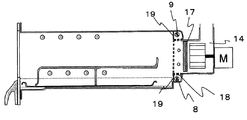
図5はロースター22の実施の形態2を示す主要部断面図である。加熱室1背面の下端部、上端部にそれぞれ下ガラス管ヒータ8、上ガラス管ヒータ9を収納し、両ガラス管ヒータを保護するために、赤外線透過材19を設置する。赤外線透過材19は一例として、石英ガラスや透明マイカなどで構成する。
収納部のうち、下ガラス管ヒータ8の上側、上ガラス管ヒータ9の下側には排気ダクト14に直結するように開口部18を設け、ガラス管ヒータから発する熱線を脱煙脱臭触媒17に当てることで加熱し、触媒反応を促進させる。
加熱室1の背面は赤外線透過材19とダクト開口部18が略同一面上に設けられており、背面に凹凸がないため、清掃作業等をしやすいという効果がある。
Embodiment 2. FIG.
FIG. 5 is a cross-sectional view of the main part showing the second embodiment of the
An
The back surface of the
実施の形態3.
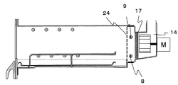
図6は実施の形態3を示すロースター22の主要部断面図である。加熱室1の背面全体を排気ダクト14の開口部18と同一化しパンチングメタル24で覆う構成とする。排気ダクト14内に設けられた下ガラス管ヒータ8、上ガラス管ヒータ9は強輻射方向の一方の面を加熱室1内側、反対側の面を脱煙脱臭触媒17に向けて設置することで、被加熱物30と脱煙脱臭触媒17を同時に加熱することが可能となるとともに、万が一ガラスが割れても、ガラスの破片が加熱室1の内側に飛び散らず、安全性を高める効果を有することができる。
Embodiment 3 FIG.
FIG. 6 is a cross-sectional view of the main part of the
実施の形態4.
図7は実施の形態4を示すロースター22の主要部断面図である。加熱室1背面の下端部、上端部にそれぞれ下ガラス管ヒータ8、上ガラス管ヒータ9を収納するとともに、ヒータ後方には、表面研磨などにより反射率0.9程度まで高めた金属製の弾性体である反射板25を設置する。反射板25には下ガラス管ヒータ8、上ガラス管ヒータ9を固定するためのヒータ固定具26を設置することで、反射板25と一体としたヒータユニットとして構成する。ヒータ固定具26は弾性を持った金属により構成し、ヒータおよび反射板などの熱膨張を吸収することで、ヒータに対する応力を逃がす効果を有する。
なお、ヒータ固定具26はヒータ支持部である。
反射板25、ヒータ固定具26、起立片27および下ガラス管ヒータ8又は上ガラス管ヒータ9はそれぞれ一体のヒータユニットとして構成され、加熱室1側から手前側に引くことで加熱室1からはずすことが可能であるため、必要に応じて部品効果や清掃が可能となる。
FIG. 7 is a cross-sectional view of the main part of the
The
The
ヒータ固定具26は下ガラス管ヒータ8、上ガラス管ヒータ9の非発熱部を支える構造とする。また、ガラスと接触する部分にはキズつき防止のため、シリコンなどの耐熱材によって被覆する。反射板25の端部には万が一ガラスが割れた場合に、その破片を受けて加熱室1側に落下することを防止する起立片27を設けることで安全性を高めることが可能となる。
The
本構成の場合、直接、脱煙脱臭触媒17に対して輻射加熱することはできないが、排気ダクト14の側壁を通して、周辺部の温度を高くすることにより、脱煙脱臭触媒17を加熱する触媒ヒータ10の加熱補助の役割を果たす。
In the case of this configuration, radiation heating cannot be directly performed on the smoke
1 加熱室、2 扉、3 視認窓、4 把手、5 レール、6 受皿、7 焼き網、8 下ガラス管ヒータ、9 上ガラス管ヒータ、10 触媒ヒータ、11 排気ファン、12 ファンモータ、13 排気口、14 排気ダクト、15 温度センサ、17 脱煙脱臭触媒、18 排気ダクト開口部、19 赤外線透過材、20 IHクッキングヒータ本体、21 誘導加熱部、22 ロースター、23 操作部(入力手段)、24 パンチングメタル、25 反射板、26 ヒータ固定具、27 起立片、30 被加熱物、31 上シーズヒータ、32 下シーズヒータ。 1 Heating chamber, 2 doors, 3 viewing windows, 4 handles, 5 rails, 6 pan, 7 grill, 8 lower glass tube heater, 9 upper glass tube heater, 10 catalyst heater, 11 exhaust fan, 12 fan motor, 13 exhaust Mouth, 14 Exhaust duct, 15 Temperature sensor, 17 Smoke deodorization catalyst, 18 Exhaust duct opening, 19 Infrared transmitting material, 20 IH cooking heater body, 21 Induction heating unit, 22 Roaster, 23 Operation unit (input means), 24 Punching Metal, 25 Reflector, 26 Heater fixture, 27 Standing piece, 30 Object to be heated, 31 Upper sheathed heater, 32 Lower sheathed heater.
Claims (1)
前記加熱室に収容される受皿と、
前記加熱室に設置され、被加熱物を加熱するガラス管ヒータと、
前記受皿と前記ガラス管ヒータとの間に設置された赤外線透過材と、を備えた
ことを特徴とする加熱調理器。 A heating chamber;
A saucer housed in the heating chamber;
A glass tube heater installed in the heating chamber for heating an object to be heated;
An infrared ray transmitting material installed between the tray and the glass tube heater.
Priority Applications (1)
| Application Number | Priority Date | Filing Date | Title |
|---|---|---|---|
| JP2012113150A JP2012187417A (en) | 2012-05-17 | 2012-05-17 | Cooker |
Applications Claiming Priority (1)
| Application Number | Priority Date | Filing Date | Title |
|---|---|---|---|
| JP2012113150A JP2012187417A (en) | 2012-05-17 | 2012-05-17 | Cooker |
Related Parent Applications (1)
| Application Number | Title | Priority Date | Filing Date |
|---|---|---|---|
| JP2008283909A Division JP5001247B2 (en) | 2008-11-05 | 2008-11-05 | Cooker |
Publications (2)
| Publication Number | Publication Date |
|---|---|
| JP2012187417A true JP2012187417A (en) | 2012-10-04 |
| JP2012187417A5 JP2012187417A5 (en) | 2013-04-18 |
Family
ID=47081198
Family Applications (1)
| Application Number | Title | Priority Date | Filing Date |
|---|---|---|---|
| JP2012113150A Pending JP2012187417A (en) | 2012-05-17 | 2012-05-17 | Cooker |
Country Status (1)
| Country | Link |
|---|---|
| JP (1) | JP2012187417A (en) |
Citations (5)
| Publication number | Priority date | Publication date | Assignee | Title |
|---|---|---|---|---|
| JPH024108U (en) * | 1988-06-16 | 1990-01-11 | ||
| JPH0336427A (en) * | 1989-07-03 | 1991-02-18 | Sanyo Electric Co Ltd | Cooking device |
| JPH0399125A (en) * | 1989-09-11 | 1991-04-24 | Matsushita Electric Ind Co Ltd | Cooking utensil |
| JP2003284649A (en) * | 2003-02-04 | 2003-10-07 | Matsushita Kotobuki Electronics Industries Ltd | Cooker |
| JP2006118818A (en) * | 2004-10-25 | 2006-05-11 | Matsushita Electric Ind Co Ltd | Heating cooker |
-
2012
- 2012-05-17 JP JP2012113150A patent/JP2012187417A/en active Pending
Patent Citations (5)
| Publication number | Priority date | Publication date | Assignee | Title |
|---|---|---|---|---|
| JPH024108U (en) * | 1988-06-16 | 1990-01-11 | ||
| JPH0336427A (en) * | 1989-07-03 | 1991-02-18 | Sanyo Electric Co Ltd | Cooking device |
| JPH0399125A (en) * | 1989-09-11 | 1991-04-24 | Matsushita Electric Ind Co Ltd | Cooking utensil |
| JP2003284649A (en) * | 2003-02-04 | 2003-10-07 | Matsushita Kotobuki Electronics Industries Ltd | Cooker |
| JP2006118818A (en) * | 2004-10-25 | 2006-05-11 | Matsushita Electric Ind Co Ltd | Heating cooker |
Similar Documents
| Publication | Publication Date | Title |
|---|---|---|
| JP5001247B2 (en) | Cooker | |
| JP5820977B2 (en) | Cooker | |
| JP5316157B2 (en) | Cooker | |
| RU2547883C2 (en) | Hybrid frying system - electrical frying element | |
| JP2010112586A (en) | Heating cooker | |
| WO2017145792A1 (en) | Induction heating cooker | |
| WO2014129208A1 (en) | Induction heat cooking instrument | |
| JP5446164B2 (en) | Cooker | |
| JP5909673B2 (en) | Cooker | |
| JP5511722B2 (en) | Cooker | |
| JP2008241219A (en) | Heating cooker | |
| JP2012187417A (en) | Cooker | |
| JP2016013259A (en) | Cooker | |
| KR101531062B1 (en) | Oven range including a duct unit | |
| JP2015007505A (en) | Heating cooker | |
| JP5197307B2 (en) | Cooker | |
| JP5629838B1 (en) | Cooker | |
| JP4103090B2 (en) | Cooker | |
| KR101531061B1 (en) | Oven range including a heat isolation means | |
| JP7370169B2 (en) | heating cooker | |
| JP2011098139A (en) | Cooker | |
| KR20080044055A (en) | Oven | |
| JP2008152982A (en) | Induction cooking device | |
| KR100697459B1 (en) | A structure of Top burner part for Electric oven | |
| JP5783938B2 (en) | Cooker |
Legal Events
| Date | Code | Title | Description |
|---|---|---|---|
| A521 | Written amendment |
Free format text: JAPANESE INTERMEDIATE CODE: A523 Effective date: 20130306 |
|
| A871 | Explanation of circumstances concerning accelerated examination |
Free format text: JAPANESE INTERMEDIATE CODE: A871 Effective date: 20130306 |
|
| A975 | Report on accelerated examination |
Free format text: JAPANESE INTERMEDIATE CODE: A971005 Effective date: 20130322 |
|
| A131 | Notification of reasons for refusal |
Free format text: JAPANESE INTERMEDIATE CODE: A131 Effective date: 20130326 |
|
| A521 | Written amendment |
Free format text: JAPANESE INTERMEDIATE CODE: A523 Effective date: 20130520 |
|
| A131 | Notification of reasons for refusal |
Free format text: JAPANESE INTERMEDIATE CODE: A131 Effective date: 20130611 |
|
| A521 | Written amendment |
Free format text: JAPANESE INTERMEDIATE CODE: A523 Effective date: 20130805 |
|
| A131 | Notification of reasons for refusal |
Free format text: JAPANESE INTERMEDIATE CODE: A131 Effective date: 20130903 |
|
| A521 | Written amendment |
Free format text: JAPANESE INTERMEDIATE CODE: A523 Effective date: 20131031 |
|
| A02 | Decision of refusal |
Free format text: JAPANESE INTERMEDIATE CODE: A02 Effective date: 20131119 |
|
| A521 | Written amendment |
Free format text: JAPANESE INTERMEDIATE CODE: A523 Effective date: 20140217 |
|
| A911 | Transfer of reconsideration by examiner before appeal (zenchi) |
Free format text: JAPANESE INTERMEDIATE CODE: A911 Effective date: 20140224 |
|
| A912 | Removal of reconsideration by examiner before appeal (zenchi) |
Free format text: JAPANESE INTERMEDIATE CODE: A912 Effective date: 20140425 |
|
| A521 | Written amendment |
Free format text: JAPANESE INTERMEDIATE CODE: A523 Effective date: 20150513 |