JP2012186741A - Image transmitting apparatus - Google Patents
Image transmitting apparatus Download PDFInfo
- Publication number
- JP2012186741A JP2012186741A JP2011049772A JP2011049772A JP2012186741A JP 2012186741 A JP2012186741 A JP 2012186741A JP 2011049772 A JP2011049772 A JP 2011049772A JP 2011049772 A JP2011049772 A JP 2011049772A JP 2012186741 A JP2012186741 A JP 2012186741A
- Authority
- JP
- Japan
- Prior art keywords
- terminal device
- image data
- main cpu
- image
- forming apparatus
- Prior art date
- Legal status (The legal status is an assumption and is not a legal conclusion. Google has not performed a legal analysis and makes no representation as to the accuracy of the status listed.)
- Withdrawn
Links
Images


Landscapes
- Facsimiles In General (AREA)
Abstract
Description
本発明は、画像データを端末装置に送信する画像送信装置に係り、特に、省電力機能を備えた端末装置に接続された画像送信装置に関する。 The present invention relates to an image transmission apparatus that transmits image data to a terminal apparatus, and more particularly to an image transmission apparatus connected to a terminal apparatus having a power saving function.
近年、オフィスや家庭などに設置される事務機器に対する省電力化の要請が高まっている。このため、PC(パーソナルコンピュータ)などの端末装置を始めプリンタや複合機などでは、実行するジョブやユーザからの操作がない待機状態が一定時間以上継続すると、通常より電力消費の少ない省電力モードへ自動的に電源モードを遷移させる機能が設けられている。 In recent years, there is an increasing demand for power saving for office equipment installed in offices and homes. For this reason, in terminal devices such as PCs (personal computers), printers, multifunction devices, etc., when a standby state in which there is no job to be executed or no operation from the user continues for a certain period of time or longer, a power saving mode in which power consumption is lower than usual is entered. A function for automatically changing the power mode is provided.
一方、複合機に関する技術の進歩が進み、ネットワークを介して複合機などの画像処理装置をPCに接続して、画像処理装置で画像を読み取り、読み取った画像データをPCに送信する機能(プッシュスキャン)などが普及している。 On the other hand, advances in technology related to multi-function peripherals have led to the ability to connect an image processing apparatus such as a multi-function peripheral to a PC via a network, read an image with the image processing apparatus, and send the read image data to the PC (push scan). ) Etc. are prevalent.
ところで、プッシュスキャンを確実かつ効率的に行うために、情報処理装置から周期的に周辺装置(MFP:Multifunction Peripheral)に対して利用登録要求を送信するようにし、周辺装置は現時点で利用登録している情報処理装置のみをプッシュスキャンによる画像データの送信先として許可するようにした画像形成装置に関するシステムが開示されている(たとえば、特許文献1参照。)。 By the way, in order to perform push scan reliably and efficiently, the information processing device periodically sends a use registration request to the peripheral device (MFP: Multifunction Peripheral), and the peripheral device is registered for use at this time. A system related to an image forming apparatus is disclosed in which only an information processing apparatus is permitted as a transmission destination of image data by push scanning (see, for example, Patent Document 1).
現在、環境保護の観点から省電力化の傾向が強まっており、たとえば、PCや事務機器などに対し、電源状態をスリープモードへ移行させるまでの待機時間が短く設定され、短時間化されると想定される。そうすると、複合機などの画像処理装置において画像データを読み取り、読み取った画像データを端末装置に送信する場合(従来のプッシュスキャンのことである。)、ユーザが画像処理装置で原稿を読み取っている間に、端末装置が短時間でスリープモードに移行してしまい、読み取った画像データを画像処理装置から端末装置に送信することができなくなる。 Currently, there is an increasing trend toward power saving from the viewpoint of environmental protection. For example, when the waiting time until the power state is shifted to the sleep mode is set short for PCs and office equipment, the time is shortened. is assumed. Then, when image data is read by an image processing apparatus such as a multifunction peripheral and the read image data is transmitted to a terminal device (this is a conventional push scan), while the user is reading a document with the image processing apparatus. In addition, the terminal device shifts to the sleep mode in a short time, and the read image data cannot be transmitted from the image processing device to the terminal device.
すなわち、プッシュスキャンを実行するために、ユーザが端末装置から画像処理装置に移動して、原稿の読み取り作業を実行している間に、端末装置がすぐにスリープモードに移行してしまい、画像処理装置で読み取った画像データを端末装置に送信することができない、という問題が生じる。この問題は、プッシュスキャンの実行時のみに限定されず、画像処理装置から画像データを端末装置に送信する際に、同様の問題が生じる。 That is, while the user moves from the terminal device to the image processing device and executes the document reading operation in order to execute the push scan, the terminal device immediately shifts to the sleep mode, and the image processing is performed. There arises a problem that image data read by the apparatus cannot be transmitted to the terminal apparatus. This problem is not limited only to the execution of push scan, and the same problem occurs when image data is transmitted from the image processing apparatus to the terminal apparatus.
特許文献1に開示されたシステムでは、周期的に利用登録を送信してくる情報処理装置のみをプッシュスキャンの送信先として許可するので、スリープモードに入っている情報処理装置は利用登録要求を送信することができず、この情報処理装置を送信先に指定するプッシュスキャンはできなかった。
In the system disclosed in
もし仮に、スリープモードにある情報処理装置に対し、周辺装置などの外部装置から起動させる技術があったとしても、スリープモードにある情報処理装置を強制的に起動させて画像データを送信すると、その情報処理装置は画像データを受信した後、再びスリープモードに入る。情報処理装置は、ユーザから入力操作がない場合にスリープモードに入るので、一時的に情報処理端末を起動しても、その情報処理装置がユーザからの入力操作を受け付けない限り、またスリープモードに入ることになる。 Even if there is a technology for starting an information processing device in the sleep mode from an external device such as a peripheral device, if the information processing device in the sleep mode is forcibly started and image data is transmitted, The information processing apparatus enters the sleep mode again after receiving the image data. Since the information processing apparatus enters the sleep mode when there is no input operation from the user, even if the information processing terminal is temporarily activated, the information processing apparatus enters the sleep mode again unless the information processing apparatus accepts the input operation from the user. Will enter.
この場合、周辺装置は、情報処理装置を一時的に起動させて情報処理装置に画像データを送ることができたとしても、画像データの送受信をさせるためだけに情報処理装置を起動させることになり、省電力効果を半減させることとなる。 In this case, even if the peripheral device can temporarily start the information processing device and send the image data to the information processing device, the peripheral device starts the information processing device only to send and receive the image data. The power saving effect will be halved.
本発明は、上記の問題を解決しようとするものであり、スリープモードに移行している端末装置に画像データを送信する際に、該端末装置側の省電力効果を確保しつつ、該端末装置のユーザが必要とするタイミングには画像データを該端末装置へ送信することができる画像送信装置を提供することを目的としている。 The present invention is intended to solve the above-described problem, and when transmitting image data to a terminal device that has shifted to a sleep mode, the terminal device is secured while ensuring a power saving effect on the terminal device side. An object of the present invention is to provide an image transmission apparatus capable of transmitting image data to the terminal device at a timing required by the user.
かかる目的を達成するための本発明の要旨とするところは、次の各項の発明に存する。 The gist of the present invention for achieving the object lies in the inventions of the following items.
[1]画像データを記憶する記憶部と、
ネットワークを介して端末装置と通信する通信部と、
前記記憶部に記憶されている画像データを、前記ネットワークに接続された端末装置へ前記通信部を介して送信する制御部と、
を備え、
前記制御部は、前記画像データを前記端末装置へ送信する際に、該端末装置の電源状態が前記画像データを受信可能な通常状態にない場合は、該端末装置の電源状態が通常状態になることを監視して、該端末装置の電源状態が通常状態になってから、前記画像データを該端末装置へ送信する
ことを特徴とする画像送信装置。
[1] A storage unit for storing image data;
A communication unit that communicates with a terminal device via a network;
A control unit that transmits the image data stored in the storage unit to the terminal device connected to the network via the communication unit;
With
When the control unit transmits the image data to the terminal device, if the power state of the terminal device is not in a normal state where the image data can be received, the power state of the terminal device becomes a normal state. The image transmission apparatus, wherein the image data is transmitted to the terminal apparatus after the power supply state of the terminal apparatus becomes a normal state.
上記発明では、制御部は、端末装置の電源状態が画像データを受信可能な通常状態にない場合は、端末装置の電源状態が通常状態になることを監視しており、端末装置の電源状態が画像データを受信可能な状態になってから端末装置に画像データを送信する。ここで、通常状態にない場合とは、電源状態がオフモードまたは省電力モードの状態などの状態を想定している。また、制御部は端末装置の電源状態が通常状態になってから画像データを即座に送信してもよく、また、自装置のうち画像データの送信に係る部分が起動していない場合は、自装置のその部分を起動させてから画像データを送信するようにしてもよい。なお、送信する画像データは、記憶部に記憶されている画像データであれば、限定されるものではない。すなわち、スキャナで読み取ったデータやファクシミリ(FAX)により受信したデータであってもよい。 In the above invention, when the power state of the terminal device is not in a normal state in which image data can be received, the control unit monitors that the power state of the terminal device becomes a normal state, and the power state of the terminal device is The image data is transmitted to the terminal device after the image data can be received. Here, the case where the power supply state is not in the normal state assumes a state where the power supply state is an off mode or a power saving mode. In addition, the control unit may transmit the image data immediately after the power state of the terminal device is in the normal state, and if the part related to the transmission of the image data in the own device is not activated, the control unit may You may make it transmit image data, after starting the part of an apparatus. The image data to be transmitted is not limited as long as it is image data stored in the storage unit. That is, it may be data read by a scanner or data received by facsimile (FAX).
[2]前記制御部は、メインCPUと、該メインCPUより消費電力の少ないサブCPUとを備え、
前記画像データを前記端末装置へ送信する際に、該端末装置の電源状態が通常状態でない場合は、前記メインCPUをオフまたは省電力モードに移行させ、前記サブCPUが前記端末装置の電源状態の監視を行う
ことを特徴とする[1]に記載の画像送信装置。
[2] The control unit includes a main CPU and a sub CPU that consumes less power than the main CPU.
When transmitting the image data to the terminal device, if the power state of the terminal device is not a normal state, the main CPU is turned off or shifted to a power saving mode, and the sub CPU is in the power state of the terminal device. The image transmitting apparatus according to [1], wherein monitoring is performed.
上記発明では、端末装置の電源状態が通常状態でない場合、制御部は画像データを端末装置に送信することができないので、制御部はメインCPUをオフまたは省電力モードに移行して省電力化を図るとともに、消費電力の少ないサブCPUが端末装置の電源状態を監視する。したがって、消費電力を抑えながら、サブCPUが端末装置の電源状態を継続して監視することができる。 In the above invention, when the power supply state of the terminal device is not a normal state, the control unit cannot transmit image data to the terminal device. Therefore, the control unit turns off the main CPU or shifts to the power saving mode to save power. At the same time, the sub CPU with low power consumption monitors the power state of the terminal device. Therefore, the sub CPU can continuously monitor the power state of the terminal device while suppressing power consumption.
[3]前記画像データの送信先の前記端末装置の電源状態が通常状態でない場合に、該端末装置の電源状態を通常状態へ移行する移行命令を該端末装置に対して送信し、該端末装置の電源状態が通常状態へ移行した後に、前記画像データを前記端末装置へ送信する強制送信モードを有する
ことを特徴とする[1]または[2]に記載の画像送信装置。
[3] When the power supply state of the terminal device to which the image data is transmitted is not a normal state, a transition command for shifting the power state of the terminal device to the normal state is transmitted to the terminal device, and the terminal device The image transmission device according to [1] or [2], wherein the image transmission device has a forced transmission mode in which the image data is transmitted to the terminal device after the power state of the device has shifted to a normal state.
上記発明では、制御部は、画像データを受信することができない電源状態から画像データを受信可能な通常状態に移行する移行命令を、端末装置に送信して、端末装置の電源状態を強制的に通常状態に移行させてから、画像データを端末装置に送信する。したがって、端末装置の電源状態を強制的に通常状態に移行させてから画像データを送信するので、画像データをより早期に送信することができる。 In the above-mentioned invention, the control unit forcibly transmits the transition command for transitioning from the power supply state where the image data cannot be received to the normal state where the image data can be received to the terminal device to forcibly set the power state of the terminal device. After shifting to the normal state, the image data is transmitted to the terminal device. Therefore, since the image data is transmitted after the power state of the terminal device is forcibly shifted to the normal state, the image data can be transmitted earlier.
[4]原稿を光学的に読み取る画像読取部を備え、
前記記憶部に記憶されている画像データは、前記画像読取部で原稿を読み取って得た画像データである
ことを特徴とする[1]乃至[3]のいずれか1つに記載の画像送信装置。
[4] An image reading unit that optically reads a document is provided,
The image transmission apparatus according to any one of [1] to [3], wherein the image data stored in the storage unit is image data obtained by reading a document with the image reading unit. .
上記発明では、原稿を光学的に読み取る画像読取部を備え、画像読取部で読み取って得た画像データを記憶部に記憶している。したがって、自装置は原稿を読み取る機能も有している。 In the above-described invention, the image reading unit that optically reads the document is provided, and the image data obtained by the image reading unit is stored in the storage unit. Therefore, the apparatus itself has a function of reading a document.
[5]前記端末装置は、メインCPUと、該メインCPUより消費電力の少ないサブCPUとを備え、外部装置からの電源状態の問い合わせに対する応答処理を前記サブCPUが行うように構成されており、
前記制御部は、メインCPUと、該メインCPUより消費電力の少ないサブCPUとを備えており、該制御部のサブCPUは、前記端末装置のサブCPUに対して該端末装置の電源状態の問い合わせを行う
ことを特徴とする[1]乃至[4]のいずれか1つに記載の画像送信装置。
[5] The terminal device includes a main CPU and a sub CPU that consumes less power than the main CPU, and is configured such that the sub CPU performs a response process for an inquiry about a power state from an external device.
The control unit includes a main CPU and a sub CPU that consumes less power than the main CPU. The sub CPU of the control unit inquires of the sub CPU of the terminal device about the power state of the terminal device. The image transmitting apparatus according to any one of [1] to [4], wherein:
上記発明では、端末装置は、メインCPUと、消費電力の少ないサブCPUとを備えており、外部装置からの問い合わせにはサブCPUが応答処理を行う。また、自装置もメインCPUと、消費電力の少ないサブCPUとを備えており、自装置のサブCPUは端末装置のサブCPUに対して、電源状態の問い合わせを行う。したがって、両装置とも、サブCPUにて通信を行うので、省電力化の相乗効果を図ることができる。 In the above invention, the terminal device includes a main CPU and a sub CPU with low power consumption, and the sub CPU performs a response process in response to an inquiry from an external device. The own device also includes a main CPU and a sub CPU with low power consumption, and the sub CPU of the own device makes an inquiry about the power state to the sub CPU of the terminal device. Therefore, since both devices communicate with each other by the sub CPU, a synergistic effect of power saving can be achieved.
本発明の画像送信装置によれば、スリープモードに移行している端末装置に画像データを送信する際に、該端末装置側の省電力効果を確保しつつ、該端末装置のユーザが必要とするタイミングには画像データを該端末装置へ送信することができる。 According to the image transmission device of the present invention, when transmitting image data to a terminal device that has shifted to the sleep mode, the user of the terminal device needs to ensure the power saving effect on the terminal device side. Image data can be transmitted to the terminal device at the timing.
以下、図面に基づき本発明の実施の形態を説明する。 Hereinafter, embodiments of the present invention will be described with reference to the drawings.
図1は、本発明の実施の形態に係る画像形成装置(画像送信装置)10が接続されたネットワークシステム5の一例を示している。画像形成装置10は、LAN(Local Area Network)などのネットワーク2を介して複数台の端末装置30(以後、PCとも呼ぶ。)と接続されている。
FIG. 1 shows an example of a
画像形成装置10は、記録紙に画像を形成して出力する機能を備えたプリンタや複合機などである。本例では、画像形成装置10は、原稿を光学的に読み取ってその複製画像を記録紙に印刷するコピージョブ、読み取った原稿の画像データをファイルにして保存したり外部端末へネットワークを通じて送信したりするスキャンジョブ、端末装置30からネットワーク2を通じて受信した印刷データに係る画像を記録紙上に形成して印刷出力する印刷ジョブなどのジョブを実行する機能を備えた複合機である。ここで、スキャンジョブのうち、画像形成装置10の操作部からジョブの投入操作を受けて、端末装置30へ画像データを送信する場合を、プッシュスキャンジョブと呼ぶ。
The
なお、上述のプッシュスキャンは、本実施の形態では、画像形成装置10の画像読取部12において原稿を読み取り、読み取った画像データをワープロソフトや読み取り専用ソフト等のファイルなどに変換して、その変換されたファイル等を端末装置30に送信する。
In the present embodiment, the above-described push scan is performed by reading an original with the
また、本実施の形態では、プッシュスキャンを例に挙げて説明するが、プッシュスキャンに限定されるものではなく、画像データを画像形成装置10から端末装置30に送信する形態であれば、適用することができる。たとえば、画像形成装置10のRAM等に画像データ等が記憶され、その画像データを端末装置30に送信する形態であればよく、ユーザによって作成された文書ファイルやダウンロードした読み取り専用の文書ファイルを画像データとして送信する形態であってもよい。
In this embodiment, push scan is described as an example. However, the present invention is not limited to push scan, and is applicable as long as image data is transmitted from the
画像形成装置10は、電源モードとして、すべての部分に通電されてジョブを実行可能な通常モードと、通常モードより電力消費の少ないスリープモードと、スリープモードよりさらに電力消費の少ないオフモードを備えている。これら電源モードの詳細については後述する。
The
また、画像形成装置10は、通常モードにおいて、ジョブを実行せずかつユーザから操作を何ら受けない状態(待機状態)が所定時間(第1設定時間、たとえば、30分)継続すると、自動的にスリープモードへ移行する機能を有している。また、スリープモードに移行してからさらに待機状態が所定時間(第2設定時間、たとえば、15分)継続すると、オフモードへ遷移するようになっている。第1、第2設定時間は任意に設定変更可能となっている。
Further, in the normal mode, the
端末装置30は、画像形成装置10に対して、印刷ジョブなどのジョブを投入してその実行などを要求する機能を備えた情報処理装置である。端末装置30は、OS(Operating System)プログラムや画像形成装置10のドライバプログラム、文書や画像を作成・編集するアプリケーションプログラムなどがインストールされたパーソナルコンピュータなどである。印刷ジョブの投入など画像形成装置10に対する各種の要求は画像形成装置10用のドライバプログラムによって行われる。
The
端末装置30も複数の電源モードを備えている。ここでは、各部へ通電されて各種の処理を実行可能な通常モード、通常モードより電力消費の少ないスリープモード、スリープモードよりさらに電力消費の少ないオフモードなどを備えている。
The
画像形成装置10は、ネットワーク2に接続されている端末装置30に対して、当該画像形成装置10用の常駐プログラムが起動しているか問い合わせし、その応答結果に応じて、プッシュスキャンで読み取った画像データを、端末装置30に送信する機能を備えている。たとえば、自装置用の常駐プログラムが起動している端末装置30に通信コマンドを送信し、端末装置30から常駐プログラムを介して適式な応答があった場合に、プッシュスキャンで読み取った画像データをその端末装置30に送信する。
The
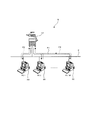
図2は、画像形成装置10の概略構成を示している。画像形成装置10は、当該画像形成装置10の動作を統括制御する制御部としてのメインCPU(Central Processing Unit)11と、このメインCPU11にバスなどを介して接続された画像読取部12と、画像形成部13と、ROM(Read Only Memory)14と、RAM(Random Access Memory)15と、表示部16と、操作部17と、画像処理部18とを備えている。画像形成装置10は、さらに、サブCPU21と、不揮発メモリ22と、ネットワークI/F部23と、ハードディスク装置24と、メモリ25と、電源部26とを備えている。
FIG. 2 shows a schematic configuration of the
サブCPU21は、メインCPU11より処理能力が小さく消費電力も少ないCPUである。メインCPU11ではOSプログラムをベースとし、その上で、ミドルウェアやアプリケーションプログラムなどが実行される。サブCPU21は、OSプログラムなしで動作し、メインCPU11に比べて、負荷の少ない処理を実行する。メインCPU11とサブCPU21により、制御部27が構成されている。
The
メインCPU11とサブCPU21は互いに信号や情報を授受可能に接続されている。画像読取部12、画像形成部13、表示部16、操作部17、画像処理部18はメインCPU11によって動作が制御される。たとえば、メインCPU11は、ネットワーク2を通じて端末装置30から受信した印刷要求に応じて、画像形成部13にその印刷要求にかかわる画像形成動作を行わせるように制御する。不揮発メモリ22、ネットワークI/F部23、ハードディスク装置24、メモリ25はメインCPU11とサブCPU21の双方からアクセス可能となっている。メモリ25や不揮発メモリ22はメインCPU11とサブCPU21との間の情報授受の媒体としても使用される。
The
電源部26は、商用電源を適宜の電圧に変換して画像形成装置10の各部へ電力を供給する。また、サブCPU21からの指示に従って、電力を供給するか供給停止するかを電力供給先別に制御する機能を備えている。ここでは、通常モードでは全ての部分に電力供給し、スリープモードでは、画像読取部12、画像形成部13、表示部16、画像処理部18、ハードディスク装置24への電源供給は停止し、オフモードではさらにメインCPU11、ROM14、RAM15への電源供給も停止する。サブCPU21、不揮発メモリ22、ネットワークI/F部23、メモリ25には、図示省略のメイン電源スイッチがオフされたり商用電源の供給が停止されたりしない限り、常時(オフモードにおいても)通電される。スリープモードでは、メインCPU11はネットワーク送受信のみ可能な状態となっている。オフモードでは、動作を停止している。
The
ROM14には各種のプログラムが格納されており、これらのプログラムに従ってメインCPU11が処理を実行することでジョブの実行といった画像形成装置10の各機能が実現される。RAM15はメインCPU11がプログラムを実行する際に各種のデータを一時的に格納するワークメモリや画像データを格納する画像メモリなどとして使用される。
Various programs are stored in the
画像読取部12は、原稿を光学的に読み取って画像データを取得する機能を果たす。画像読取部12は、たとえば、原稿に光を照射する光源と、その反射光を受けて原稿を幅方向に1ライン分読み取るラインイメージセンサと、ライン単位の読取位置を原稿の長さ方向に順次移動させる移動手段と、原稿からの反射光をラインイメージセンサに導いて結像させるレンズやミラーなどからなる光学経路、ラインイメージセンサの出力するアナログ画像信号をデジタルの画像データに変換する変換部などを備えて構成される。
The
画像形成部13は、画像データに応じた画像を記録紙上に画像形成する機能を果たす。ここでは、記録紙の搬送装置と、感光体ドラムと、帯電装置と、レーザーユニットと、現像装置と、転写分離装置と、クリーニング装置と、定着装置とを有し、電子写真プロセスによって画像形成を行う、所謂、レーザープリンタとして構成されている。画像形成は他の方式でもかまわない。
The
画像形成装置10の操作パネルは表示部16と操作部17を備えて構成される。表示部16は、液晶ディスプレイ(LCD…Liquid Crystal Display)などで構成され、各種の操作画面、設定画面などを表示する機能を果たす。操作部17は、ユーザからジョブの投入や設定など各種の操作を受け付ける機能を果たす。操作部17は、表示部16の画面上に設けられて押下された座標位置を検出するタッチパネルのほかテンキーや文字入力キー、スタートキーなどを備えて構成される。
The operation panel of the
画像処理部18は、画像の拡大縮小、回転などの処理のほか、印刷データをイメージデータに変換するラスタライズ処理、画像データの圧縮、伸張処理などを行う。
The
メモリ25はサブCPU21のワークメモリとして使用される。不揮発メモリ22は、電源がオフされても記憶内容が破壊されないメモリ(フラッシュメモリ)である。不揮発メモリ22には、各端末装置30の電源状態またはドライバプログラム(常駐プログラムも含む。)のインストール状況を問い合わせた結果などが記憶されるほか、サブCPU21が実行するプログラムなども記憶されている。ネットワークI/F部23は、ネットワーク2を通じて端末装置30やその他の外部装置と各種のデータを送受信する機能を果たす。ハードディスク装置24は、大容量不揮発の記憶装置であり、たとえば、印刷データや画像データの保存に使用される。
The
画像形成装置10は、メインCPU11などへの電力供給が完全にオフするオフモードにおいても、サブCPU21が稼動しており、該サブCPU21が稼動している状態であれば、メモリ25や不揮発メモリ22へのアクセス、ネットワークI/F部23による通信を行うことができる。すなわち、ネットワークI/F部23はサブCPU21によってルーティングされ、OS上のソフトウェアに依存することなく、ネットワーク2を介して端末装置30などの外部装置と特定のプロトコルによって通信することができる。
In the
図3は、端末装置30の概略構成の一例を示している。端末装置30は、メインCPU31と、サブCPU32と、ROM33と、RAM34と、入出力I/F部35と、不揮発メモリ36と、ネットワークI/F部37と、ハードディスク装置(HDD)38と、メモリ39と、電源部41とを備えている。さらに入出力I/F部35を介して、液晶ディスプレイなどの表示装置42と、キーボードやマウスなどの入力デバイス43が接続されている。
FIG. 3 shows an example of a schematic configuration of the
ROM33には起動用のプログラムや固定データが記憶される。RAM34は、ハードディスク装置38からロードしたプログラムが記憶される。またRAM34は、メインCPU31がプログラムを実行する際に各種のデータを一時的に格納するワークメモリなどとして使用される。
The
不揮発メモリ36は、電源をオフにしても記憶内容が破壊されないメモリ(フラッシュメモリ)であり、ドライバプログラムのインストール状況を示すドライバ情報などが記憶される。ネットワークI/F部37は、ネットワーク2を介して画像形成装置10や他の外部装置と各種のデータを送受信する機能を果たす。ハードディスク装置38は、大容量不揮発の記憶装置であり、OSプログラムや画像形成装置10のドライバプログラム、ミドルウェア、各種アプリケーションプログラム、ファイル、データなどが保存される。また、画像形成装置10用の常駐プログラムがインストールされるとハードディスク装置38に格納される。
The
端末装置30においても、サブCPU32は、メインCPU31より処理能力が小さく消費電力も少ないCPUである。メインCPU31ではOSプログラムをベースとし、その上で、ミドルウェアやアプリケーションプログラムなどが実行される。サブCPU32は、OSプログラムなしで動作し、メインCPU31に比べて、負荷の少ない処理を実行する。
Also in the
メインCPU31とサブCPU32は互いに信号や情報を授受可能に接続されている。不揮発メモリ36、ネットワークI/F部37、ハードディスク装置38、メモリ39はメインCPU31とサブCPU32の双方からアクセス可能となっている。メモリ39や不揮発メモリ36はメインCPU31とサブCPU32との間の情報授受の媒体としても使用される。
The
電源部41は、商用電源を適宜の電圧に変換して端末装置30の各部へ電力を供給する。また、サブCPU32からの指示に従って、電力を供給するか供給停止するかを電力供給先別に制御する機能を備えている。ここでは、通常モードでは全ての部分に電力供給し、スリープモードでは、入出力I/F部35、ハードディスク装置38への電源供給は停止し、オフモードではさらにメインCPU31、ROM33、RAM34への電源供給も停止する。サブCPU32、不揮発メモリ36、ネットワークI/F部37、メモリ39には、図示省略のメイン電源スイッチがオフされたり商用電源の供給が停止されたりしない限り、常時(オフモードでも)通電される。またスリープモードでは、メインCPU31は、たとえば通常モードの10パーセント程度に処理能力を下げて電力消費を抑えたスリープ状態に遷移する。
The
端末装置30は、画像形成装置10と同様に、メインCPU31などへの電力供給が完全にオフされるオフモードにおいても、サブCPU32が稼動しており、該サブCPU32が稼動している状態であれば、メモリ39や不揮発メモリ36へのアクセス、ネットワークI/F部37による通信を行うことができる。すなわち、ネットワークI/F部37はサブCPU32によってルーティングされ、OS上のソフトウェアに依存することなく、ネットワーク2を介して画像形成装置10などの外部装置と特定のプロトコルによって通信することができる。
Similarly to the
なお、本実施の形態では、端末装置30の電源状態は、画像形成装置10のサブCPU21が監視を行うものとし、端末装置30のサブCPU32が応答するものとする。したがって、端末装置30のサブCPU32は、端末装置30のメインCPU31がオフモードまたはスリープモードであっても、後述する画像形成装置10からの電源状態監視要求に応答することができる。また、端末装置30は、端末装置30のメインCPU31が稼動している通常状態でのみ画像形成装置10のメインCPU11から送信される画像データを受信することができる。
In the present embodiment, the power state of the
また、本実施の形態では、画像形成装置10は、プッシュスキャンを実行するモードとして、強制起動モードと監視モードの2つのモードを有している。したがって、ユーザは、プッシュスキャンを実行する際に、画像形成装置10の操作部17を操作して、強制起動モードか監視モードかを選択する。監視モードでは、画像データを送信する際に、送信先の端末装置30のメインCPU31がオフモードまたはスリープモードの場合には、画像形成装置10のサブCPU21は、その端末装置30の電源状態が画像データを受信可能な通常状態になってから、画像データを端末装置30に送信する。一方、強制起動モードでは、画像データを送信する際に、送信先の端末装置30がオフモードまたはスリープの場合には、その端末装置30に対して電源状態を通常状態へ移行させる旨の移行命令を送信し、その端末装置30の電源状態を強制的に通常状態に移行させてから画像データを送信するようになっている。
In the present embodiment, the
なお、いずれのモードにおいても、画像データを送信する際に送信先の端末装置30の電源状態が受信可能な通常状態であれば、その時点で画像データを端末装置30に対して送信する。
In any mode, when the image data is transmitted, if the power state of the
次に、画像形成装置10を使用するためのドライバプログラム(常駐プログラムを含む。)をインストールする際の端末装置30に係る動作について説明する。
Next, an operation related to the
端末装置30は、画像形成装置10を最初に使用する際に、その画像形成装置10に対応するドライバプログラム(プリンタドライバやスキャナドライバ、ファクシミリドライバなど画像形成装置10を利用するためのプログラム)をOSプログラム上でインストールする必要がある。ドライバプログラムが端末装置30にインストールされると、当該インストールプログラムあるいはドライバプログラムの初期化処理において、そのドライバプログラムの情報(ドライバ名、メーカー名、バージョン、言語、ポート、インストール日時などのドライバ情報)を端末装置30の不揮発メモリ36(不揮発記憶領域)に書き込む。ドライバプログラムの1つに常駐プログラムも含まれる。図4は、不揮発メモリ36(不揮発記憶領域)に記憶された常駐プログラムのドライバ情報51の一例を示している。
When the
なお、常駐プログラムのドライバ情報は、対応するドライバプログラムがアンインストールされる際に不揮発メモリ36から削除される。また、ドライバプログラムをインストールした後、端末装置30が画像形成装置10から画像データを受信した場合、最後に画像データを受信した時間(タイムスタンプ、図4のドライバ情報51ではLast Jobの日時)を不揮発メモリ36に書き込み、更新するようになっている。該更新はメインCPU31が行ってもよいし、サブCPU32が行ってもよい。ここでは、ジョブを受信した常駐プログラムがタイムスタンプを更新するようになっている。また、最後に画像データを受信したことを、便宜上、「Last Job」という。
The driver information of the resident program is deleted from the
端末装置30にインストールされた常駐プログラムは、端末装置30のメインCPU31が起動中に、画像形成装置10のメインCPU11からの通信コマンドを受信すると、応答パケットを返信する処理を行う。その動作について詳述する。
The resident program installed in the
まず、画像形成装置10が、端末装置30の常駐プログラムに通信コマンドを送信する一例について説明する。
First, an example in which the
図5は、不揮発記憶領域の情報取得要求61として送信する通信コマンドのパケットのデータ構成例を示している。図5に示す不揮発記憶領域の情報取得要求61として送信するパケットには、送信元IPアドレス(Internet Protocol Address)として画像形成装置10のIPアドレスが、送信先IPアドレスとして送信先である端末装置30のIPアドレスが、データ部には、「不揮発記憶領域の情報取得要求」を示すコマンドが書き込まれている。
FIG. 5 shows a data configuration example of a packet of a communication command transmitted as the
具体的には、送信元である画像形成装置10のIPアドレスには「192.168.0.1」が記載され、送信先である端末装置30のIPアドレスには、「192.168.0.2」が記載され、データ部には、「不揮発記憶領域の情報取得要求」を示すコマンドとして、「GetStorageData」が記載されている。「GetStorageData」とは、端末装置30の不揮発メモリ36に記載されたデータを取得する処理を意味している。
Specifically, “192.168.0.1” is described in the IP address of the
画像形成装置10のメインCPU11が通信コマンドを送信すると、端末装置30のネットワークI/F部37は、通信コマンドのパケットを受信する。端末装置30のメインCPU31は、ネットワークI/F部37が受信したパケットを解析する。そして、特定のプロトコルによるパケットであると判断した場合、そのデータ部に書かれているコマンドを実行する。図5の例では、画像形成装置10によってユニキャストされた不揮発記憶領域の情報取得要求61を受信したとき、そのデータ部に「GetStorageData」のコマンドが書き込まれているため、端末装置30のメインCPU31は、このコマンドに対応した処理を実行する。
When the
すなわち、端末装置30のメインCPU31は、「GetStorageData」コマンドを実行し、不揮発記憶領域の情報を不揮発メモリ36から取得すると、ACK(Acknowledgement:肯定応答)として応答パケットを返信する。
That is, when the
図6は、「GetStorageData」のコマンドに対する情報取得応答(ドライバ情報応答)64のパケットのデータ構成例を示している。図6に示す情報取得応答64では、送信元IPアドレスとして端末装置30のIPアドレスが、送信先IPアドレスとして画像形成装置10のIPアドレスが、データ部に不揮発メモリ36(不揮発記憶領域)から読み出した情報(ドライバ情報)が書き込まれている。
FIG. 6 shows a data configuration example of a packet of an information acquisition response (driver information response) 64 in response to a command “GetStorageData”. In the
具体的には、送信元である端末装置30のIPアドレスには、「192.168.0.2」が記載され、送信先である画像形成装置10のIPアドレスには「192.168.0.1」が記載され、データ部には、不揮発メモリ36(不揮発記憶領域)から読み出されたドライバ情報が記載されている。
Specifically, “192.168.0.2” is described in the IP address of the
次に、不揮発記憶領域の情報取得要求61の応答に係る動作について説明する。
Next, an operation related to a response to the
図7は、端末装置30のメインCPU31が不揮発記憶領域の情報取得応答64として返信する動作の流れについて説明する。
FIG. 7 explains the flow of the operation that the
端末装置30のメインCPU31は、不揮発記憶領域の情報取得要求61を受信すると(ステップS101;Yes)、不揮発メモリ36(不揮発記憶領域)に記憶されている情報(ドライバ情報)を読み出し(ステップS102)、応答パケットとして情報取得応答64を作成し、これを画像形成装置10に対して送信する(ステップS103)。
When the
画像形成装置10のメインCPU11は、情報取得応答64を受信して、情報取得応答64のドライバ情報が画像形成装置10の情報と一致すれば、端末装置30のメインCPU31は、画像形成装置10のメインCPU11が送信する画像データを受信することができると判断する。
When the
詳細には、受信した情報取得応答64からその送信元の端末装置30にインストールされているドライバプログラムに関する情報を抽出し、ドライバ名とメーカー名などについて、予め記憶している自装置用のそれらと情報取得応答64から抽出したものとの照合を行い、自装置用のドライバプログラムであるか否かを判断する。
Specifically, information on the driver program installed in the
次に、電源状態取得要求P1の応答に係る動作について説明する。 Next, an operation related to a response to the power supply status acquisition request P1 will be described.
図8は、電源状態取得要求P1を受信した端末装置30側の動作を示している。図1に示すように、画像形成装置10のサブCPU21は、ネットワーク2に接続されている端末装置30に対して、端末装置30の電源状態を問い合わせる。
FIG. 8 shows the operation on the
端末装置30のサブCPU32は、電源状態取得要求P1を受信すると(ステップS121;Yes)、現在の電源状態の情報を取得して(ステップS122)、電源状態を示す情報をデータ部に格納した応答パケットを作成して画像形成装置10に返信する(ステップS123、図1:P2)。
When the
画像形成装置10のサブCPU21は、端末装置30から電源状態取得応答パケットP2を受信すると、送信元である端末装置30のメインCPU31の電源状態を把握することができ、端末装置30が画像データを受信することができるか否かを判断することができる。なお、本実施の形態では、端末装置30のメインCPU31が稼動している通常状態でのみ画像形成装置10から画像データを受信することができる。
When receiving the power status acquisition response packet P2 from the
次に、画像形成装置10のプッシュスキャンに係る動作について説明する。
Next, an operation related to push scanning of the
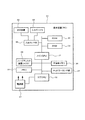
図9は、画像形成装置10が行うプッシュスキャンに係る動作を示している。まず、ユーザは、端末装置30から画像形成装置10に移動し、画像形成装置10の画像読取部12で原稿を読み取る設定作業を行う。
FIG. 9 shows operations related to push scan performed by the
具体的には、ユーザは、画像形成装置10に読み取らせる原稿を画像読取部12にセットする。そして、ユーザは、画像形成装置10の操作部17を操作し、読み取った画像データを監視モードか強制起動モードのいずれかで送信するかを設定する。また、画像データの送信先も設定し、たとえば、送信先として任意の端末装置30であるPC1(図1)に指定して、読み取った画像データを画像形成装置10からPC1に送信する設定を行う。これらの設定を行い、ユーザは、画像形成装置10の操作部17に設けられたプッシュスキャンを開始するスタートボタンを押下操作することにより、プッシュスキャンの動作が開始する。
Specifically, the user sets a document to be read by the
画像形成装置10のメインCPU11は、画像読取部12により原稿を読み取り、読み取った画像データをRAM15に格納する(ステップS201)。画像形成装置10のメインCPU11は、読み取った画像データを送信先として指定された端末装置30(たとえば、PC1。)に送信するため、不揮発記憶領域の情報取得要求61(図5)を所定の端末装置30の常駐プログラムに通信コマンドとして送信する(ステップS202)。
The
ここで、端末装置30のメインCPU31は、環境配慮の観点から、消費電力を低減し省エネルギーとなる処理を推進しており、電源状態をスリープモードへ移行させるまでの待機時間が短く設定されている。したがって、端末装置30のメインCPU31は、ユーザが自席を離れて画像形成装置10の操作部17でプッシュスキャンの設定をしている間や画像形成装置10の画像読取部12が原稿の読み取りを行っている間に、端末装置30のメインCPU31はスリープモードに移行するようになっている。
Here, the
画像形成装置10のメインCPU11は、端末装置30の常駐プログラムから不揮発記憶領域の情報取得応答64(図6)を受信すると、自装置用のドライバプログラムがインストールされているか否かを判定し(ステップS203)、自装置用のドライバプログラムがインストールされている場合には(ステップS203;Yes)、画像形成装置10のメインCPU11は、RAM15に格納した画像データを、送信先として指定された端末装置30に送信する(ステップS204)。
When the
一方、不揮発記憶領域の情報取得応答64を受信することができない場合には、画像形成装置10のメインCPU11は、端末装置30の電源状態は画像データを受信することができない状態と判定し(ステップS203;No)、画像形成装置10のサブCPU21は、端末装置30に電源状態取得要求P1を送信する(ステップS205)。
On the other hand, when the
端末装置30のサブCPU32は、電源状態取得要求P1を受信すると、電源状態取得応答パケットP2を作成し、正常に電源状態取得応答パケットP2を作成することができれば、画像形成装置10のサブCPU21に電源状態取得応答パケットP2を送信する。ここで、端末装置30のサブCPU32が、電源状態取得応答パケットP2を送信することができない場合は、画像形成装置10のサブCPU21は、端末装置30と通信することができない状態と判定し(ステップS206;No)、端末装置30にエラーが発生している旨の通知を行う(ステップS207)。たとえば、画像形成装置10の表示部16に、「192.168.0.2」の端末装置30と通信できません。あるいは「192.168.0.2」の端末装置30に接続エラーが発生しました。などのエラーの通知を行う。
When the
一方、電源状態取得応答パケットP2を受信することができたときは、画像形成装置10のサブCPU21は、端末装置30のサブCPU32と通信することができると判定し(ステップS206;Yes)、端末装置30のメインCPU31が起動中か否かを判定する(ステップS208)。
On the other hand, when the power state acquisition response packet P2 can be received, the
端末装置30のメインCPU31が起動中の場合には(ステップS208;Yes)、画像形成装置10のサブCPU21は、画像データを端末装置30のメインCPU31が受信可能と判定し、もし、画像形成装置10のメインCPU11がスリープモード等の省電力モードに移行していればメインCPU11を起動させ(ステップS209)、ステップS202に戻り、画像形成装置10のメインCPU11から端末装置30のメインCPU31に画像データの送信を行う。この場合、画像形成装置10のメインCPU11と端末装置30のメインCPU31がともに起動しているので、正常に画像データを送信することができる。
When the
一方、端末装置30のメインCPU31が起動していない場合には(ステップS208;No)、端末装置30を強制的に起動して送信する強制起動モードか否かを判定し(ステップS210)、強制起動モードでない場合には(ステップS210;No)、画像形成装置10のサブCPU21は、ステップS205に戻り、引き続き、電源状態取得要求P1を端末装置30のサブCPU32に送信する。
On the other hand, if the
この場合、画像形成装置10のサブCPU21は、端末装置30のメインCPU31が起動するまで待ち受ける処理となる。
In this case, the
これに対し、端末装置30のメインCPU31を強制的に起動する強制起動モードの場合には(ステップS210;Yes)、画像形成装置10のサブCPU21は、端末装置30の電源状態を強制的に通常状態へ移行させる移行命令を送信先の端末装置30(たとえば、PC1。)に対して送信し、端末装置30の電源状態を通常状態へ移行させる(ステップS211)。画像形成装置10のサブCPU21は、ステップS202に戻り、端末装置30の電源状態が通常状態へ移行した後に、画像形成装置10のメインCPU11から端末装置30のメインCPU31に画像データを送信させる(ステップS204)。
On the other hand, in the forced activation mode in which the
この場合、画像形成装置10のメインCPU11と端末装置30のメインCPU31はともに起動しており、通信可能な状態となるので、確実に画像データを送信することができる。
In this case, both the
また、ステップS208において、端末装置30のメインCPU31が起動していない場合には、画像形成装置10のメインCPU11は、画像データを送信する処理が発生しないため、予め設定された第1設定時間が経過すると、省電力モードに移行する。また省電力モードに限定されず、第2設定時間が経過した場合には、オフモードに移行してもよい。
In step S208, when the
このように、本実施の形態に係る画像形成装置10では、画像形成装置10のメインCPU11が画像データを送信する際に、端末装置30のメインCPU31の電源状態が、画像データを受信可能な通常状態にない場合は、画像形成装置10のサブCPU21が端末装置30のサブCPU32と通信を行い、端末装置30のメインCPU31の起動状態を監視する。これにより、画像形成装置10のサブCPU21は、端末装置30のメインCPU31が起動して、画像データを受信可能な通常の電源状態になってから、画像形成装置10のメインCPU11から端末装置30のメインCPU31に画像データを送信する。
As described above, in the
すなわち、ユーザがプッシュスキャンを実行するために画像形成装置10が設置された場所まで行き、画像形成装置10でプッシュスキャンの設定や画像形成装置10が読み取り動作を行っているときに、端末装置30のメインCPU31はスリープモード等などの省電力モードに移行するので、画像形成装置10のメインCPU11は画像データを送信しない。しかし、ユーザが画像形成装置10から自席に戻り、キーボードやマウス等を操作することにより、端末装置30のメインCPU31が起動すると、画像形成装置10のメインCPU11から端末装置30のメインCPU31に画像データが送信される。
That is, when the user goes to the place where the
このように、本実施の形態によれば、端末装置30のメインCPU31が、省電力モードにある時間を長く確保することができ、かつ端末装置30の不必要な起動を抑え、省電力化を図ることができる。また、ユーザが自席に戻ったときに画像形成装置10から画像データが送信されるので、ユーザは、画像データを必要とするタイミングで画像データを取得することができる。
Thus, according to the present embodiment, the
以上、本発明の実施の形態を図面によって説明してきたが、具体的な構成は実施の形態に示したものに限られるものではなく、本発明の要旨を逸脱しない範囲における変更や追加があっても本発明に含まれる。 The embodiment of the present invention has been described with reference to the drawings. However, the specific configuration is not limited to that shown in the embodiment, and there are changes and additions within the scope of the present invention. Are also included in the present invention.
たとえば、送信対象の画像データがすでにRAM15やハードディスク装置(HDD)24などに記憶されている場合、原稿から画像データを読み取る処理を実行せずに、送信ファイルや送信先の指示を含む送信ジョブの設定を、画像形成装置10本体が有する操作部17から受け付けるようにしてもよい。
For example, when the image data to be transmitted is already stored in the
また、本実施の形態はこれに限らず、画像形成装置10は、外部装置から送信指示を受け付けるようにしてもよい。たとえば、図1の説明図において、画像形成装置10は、PC2に画像データを送信する送信指示をPC1から受け付けて、送信先となるPC2に画像データを送信することができる。この場合、PC2がスリープモードやオフモードの場合には、画像形成装置10は、PC2の電源状態が通常状態に移行するまで待ってから、画像データの送信を行うことができる。
The present embodiment is not limited to this, and the
2…ネットワーク
5…ネットワークシステム
10…画像形成装置(MFP)
11…メインCPU
12…画像読取部
13…画像形成部
14…ROM
15…RAM
16…表示部
17…操作部
18…画像処理部
21…サブCPU
22…不揮発メモリ
23…ネットワークI/F部
24…ハードディスク装置(HDD)
25…メモリ
26…電源部
27…制御部
30…端末装置(PC)
31…メインCPU
32…サブCPU
33…ROM
34…RAM
35…入出力I/F部
36…不揮発メモリ
37…ネットワークI/F部
38…ハードディスク装置(HDD)
39…メモリ
41…電源部
42…表示装置
43…入力デバイス
51…ドライバ情報
61…情報取得要求
64…情報取得応答
2 ...
11 ... Main CPU
12 ...
15 ... RAM
16 ...
22 ...
25 ...
31 ... Main CPU
32 ... Sub CPU
33 ... ROM
34 ... RAM
35 ... Input / output I /
DESCRIPTION OF
Claims (5)
ネットワークを介して端末装置と通信する通信部と、
前記記憶部に記憶されている画像データを、前記ネットワークに接続された端末装置へ前記通信部を介して送信する制御部と、
を備え、
前記制御部は、前記画像データを前記端末装置へ送信する際に、該端末装置の電源状態が前記画像データを受信可能な通常状態にない場合は、該端末装置の電源状態が通常状態になることを監視して、該端末装置の電源状態が通常状態になってから、前記画像データを該端末装置へ送信する
ことを特徴とする画像送信装置。 A storage unit for storing image data;
A communication unit that communicates with a terminal device via a network;
A control unit that transmits the image data stored in the storage unit to the terminal device connected to the network via the communication unit;
With
When the control unit transmits the image data to the terminal device, if the power state of the terminal device is not in a normal state where the image data can be received, the power state of the terminal device becomes a normal state. The image transmission apparatus, wherein the image data is transmitted to the terminal apparatus after the power supply state of the terminal apparatus becomes a normal state.
前記画像データを前記端末装置へ送信する際に、該端末装置の電源状態が通常状態でない場合は、前記メインCPUをオフまたは省電力モードに移行させ、前記サブCPUが前記端末装置の電源状態の監視を行う
ことを特徴とする請求項1に記載の画像送信装置。 The control unit includes a main CPU and a sub CPU that consumes less power than the main CPU.
When transmitting the image data to the terminal device, if the power state of the terminal device is not a normal state, the main CPU is turned off or shifted to a power saving mode, and the sub CPU is in the power state of the terminal device. The image transmission apparatus according to claim 1, wherein monitoring is performed.
ことを特徴とする請求項1または2に記載の画像送信装置。 When the power state of the terminal device that is the transmission destination of the image data is not a normal state, a transition command for shifting the power state of the terminal device to the normal state is transmitted to the terminal device, and the power state of the terminal device The image transmission device according to claim 1, wherein the image transmission device has a forced transmission mode in which the image data is transmitted to the terminal device after transition to a normal state.
前記記憶部に記憶されている画像データは、前記画像読取部で原稿を読み取って得た画像データである
ことを特徴とする請求項1乃至3のいずれか1つに記載の画像送信装置。 An image reading unit for optically reading a document;
The image transmission apparatus according to any one of claims 1 to 3, wherein the image data stored in the storage unit is image data obtained by reading a document with the image reading unit.
前記制御部は、メインCPUと、該メインCPUより消費電力の少ないサブCPUとを備えており、該制御部のサブCPUは、前記端末装置のサブCPUに対して該端末装置の電源状態の問い合わせを行う
ことを特徴とする請求項1乃至4のいずれか1つに記載の画像送信装置。 The terminal device includes a main CPU and a sub CPU that consumes less power than the main CPU, and is configured such that the sub CPU performs a response process to an inquiry about a power state from an external device.
The control unit includes a main CPU and a sub CPU that consumes less power than the main CPU. The sub CPU of the control unit inquires of the sub CPU of the terminal device about the power state of the terminal device. The image transmitting apparatus according to claim 1, wherein:
Priority Applications (1)
| Application Number | Priority Date | Filing Date | Title |
|---|---|---|---|
| JP2011049772A JP2012186741A (en) | 2011-03-08 | 2011-03-08 | Image transmitting apparatus |
Applications Claiming Priority (1)
| Application Number | Priority Date | Filing Date | Title |
|---|---|---|---|
| JP2011049772A JP2012186741A (en) | 2011-03-08 | 2011-03-08 | Image transmitting apparatus |
Publications (1)
| Publication Number | Publication Date |
|---|---|
| JP2012186741A true JP2012186741A (en) | 2012-09-27 |
Family
ID=47016391
Family Applications (1)
| Application Number | Title | Priority Date | Filing Date |
|---|---|---|---|
| JP2011049772A Withdrawn JP2012186741A (en) | 2011-03-08 | 2011-03-08 | Image transmitting apparatus |
Country Status (1)
| Country | Link |
|---|---|
| JP (1) | JP2012186741A (en) |
-
2011
- 2011-03-08 JP JP2011049772A patent/JP2012186741A/en not_active Withdrawn
Similar Documents
| Publication | Publication Date | Title |
|---|---|---|
| JP5545466B2 (en) | Image forming system, image forming apparatus, and image forming program | |
| EP2293147B1 (en) | Image Forming Apparatus And Method Of Controlling Low Power Thereof | |
| JP6351306B2 (en) | Image processing apparatus, image processing apparatus control method, and program | |
| JP6140994B2 (en) | Printing system, printing control apparatus, printing control apparatus control method, and program | |
| US8543677B2 (en) | Communication control device, method, and computer readable medium allowing an information processing device to be in a power saving mode for an extended period and allowing an application part to continue functioning | |
| US10469676B2 (en) | Image forming systems, and methods of using same | |
| JP2017177573A (en) | Information processing device provided with pci (peripheral component interconnect) device with connecting to pci bus and method for controlling information processing device | |
| JP2013158956A (en) | Image processing apparatus including image data saving function | |
| JP2015177315A (en) | Image forming apparatus, control method of image forming apparatus, and program | |
| JP2012160877A (en) | Image processor | |
| JP6108710B2 (en) | Information processing apparatus, information processing apparatus control method, and program | |
| JP2018093422A (en) | Image forming apparatus and control program for image forming apparatus | |
| JP6132535B2 (en) | Printing system, printing control apparatus, printing control apparatus control method, and program | |
| JP2011194749A (en) | Image forming device | |
| JP2012237905A (en) | Image forming device | |
| JP6079299B2 (en) | Print system, program, starter | |
| JP2011065548A (en) | Apparatus, program and system for forming image | |
| JP2006095741A (en) | Information processing equipment | |
| JP2010197632A (en) | Image forming apparatus | |
| JP5396791B2 (en) | Image forming apparatus and program | |
| JP2012186741A (en) | Image transmitting apparatus | |
| JP5779840B2 (en) | Image processing apparatus, device cooperation system, power return control method, program | |
| JP2011020267A (en) | Printer and printing system | |
| JP5488248B2 (en) | Image processing device | |
| JP2019084768A (en) | Image forming apparatus, control method, and program |
Legal Events
| Date | Code | Title | Description |
|---|---|---|---|
| A711 | Notification of change in applicant |
Free format text: JAPANESE INTERMEDIATE CODE: A712 Effective date: 20130417 |
|
| A300 | Withdrawal of application because of no request for examination |
Free format text: JAPANESE INTERMEDIATE CODE: A300 Effective date: 20140513 |