JP2012186574A - On-vehicle camera device - Google Patents
On-vehicle camera device Download PDFInfo
- Publication number
- JP2012186574A JP2012186574A JP2011047079A JP2011047079A JP2012186574A JP 2012186574 A JP2012186574 A JP 2012186574A JP 2011047079 A JP2011047079 A JP 2011047079A JP 2011047079 A JP2011047079 A JP 2011047079A JP 2012186574 A JP2012186574 A JP 2012186574A
- Authority
- JP
- Japan
- Prior art keywords
- signal
- imaging unit
- image
- unit
- imaging
- Prior art date
- Legal status (The legal status is an assumption and is not a legal conclusion. Google has not performed a legal analysis and makes no representation as to the accuracy of the status listed.)
- Granted
Links
- 238000003384 imaging method Methods 0.000 claims abstract description 198
- 230000005540 biological transmission Effects 0.000 claims abstract description 44
- 239000011324 bead Substances 0.000 claims description 2
- 239000003990 capacitor Substances 0.000 claims description 2
- 238000013016 damping Methods 0.000 claims description 2
- 229910000859 α-Fe Inorganic materials 0.000 claims description 2
- 230000005855 radiation Effects 0.000 abstract description 16
- 230000002123 temporal effect Effects 0.000 abstract description 5
- 238000010586 diagram Methods 0.000 description 12
- 238000004891 communication Methods 0.000 description 9
- 230000003111 delayed effect Effects 0.000 description 4
- 230000001360 synchronised effect Effects 0.000 description 2
- 239000006096 absorbing agent Substances 0.000 description 1
- 230000000694 effects Effects 0.000 description 1
- 238000005516 engineering process Methods 0.000 description 1
- 238000009434 installation Methods 0.000 description 1
- 238000000034 method Methods 0.000 description 1
- 238000000926 separation method Methods 0.000 description 1
- 230000011664 signaling Effects 0.000 description 1
Images


Classifications
-
- H—ELECTRICITY
- H04—ELECTRIC COMMUNICATION TECHNIQUE
- H04N—PICTORIAL COMMUNICATION, e.g. TELEVISION
- H04N7/00—Television systems
- H04N7/18—Closed-circuit television [CCTV] systems, i.e. systems in which the video signal is not broadcast
-
- H—ELECTRICITY
- H04—ELECTRIC COMMUNICATION TECHNIQUE
- H04N—PICTORIAL COMMUNICATION, e.g. TELEVISION
- H04N13/00—Stereoscopic video systems; Multi-view video systems; Details thereof
- H04N13/20—Image signal generators
- H04N13/204—Image signal generators using stereoscopic image cameras
- H04N13/239—Image signal generators using stereoscopic image cameras using two 2D image sensors having a relative position equal to or related to the interocular distance
-
- H—ELECTRICITY
- H04—ELECTRIC COMMUNICATION TECHNIQUE
- H04N—PICTORIAL COMMUNICATION, e.g. TELEVISION
- H04N13/00—Stereoscopic video systems; Multi-view video systems; Details thereof
- H04N13/20—Image signal generators
- H04N13/296—Synchronisation thereof; Control thereof
-
- H—ELECTRICITY
- H04—ELECTRIC COMMUNICATION TECHNIQUE
- H04N—PICTORIAL COMMUNICATION, e.g. TELEVISION
- H04N13/00—Stereoscopic video systems; Multi-view video systems; Details thereof
- H04N2013/0074—Stereoscopic image analysis
- H04N2013/0081—Depth or disparity estimation from stereoscopic image signals
Landscapes
- Engineering & Computer Science (AREA)
- Multimedia (AREA)
- Signal Processing (AREA)
- Studio Devices (AREA)
Abstract
Description
本発明は、自動車に搭載する車載カメラ装置に関する。 The present invention relates to an in-vehicle camera device mounted on an automobile.
近年、車載安全装置の一つとして、外界認識センサである車載カメラ装置を用いた技術開発が進んでいる。特に、2つの撮像部を持つステレオカメラ技術の開発が進んでいる。 In recent years, as one of in-vehicle safety devices, technological development using an in-vehicle camera device that is an external recognition sensor has been advanced. In particular, the development of stereo camera technology having two image capturing units is in progress.
ステレオカメラは、左右それぞれに撮像部を持っており、画像制御部が左右の撮像部の撮像タイミングや画像データの送信タイミングを制御している。 The stereo camera has imaging units on the left and right sides, and the image control unit controls the imaging timing of the left and right imaging units and the transmission timing of image data.
左右の撮像部から送信された画像データ信号は、カメラの中央部のある画像処理部まで伝送して、画像処理をする。その後、画像処理部で処理した画像を用いて認識アプリケーション等が対象物の認識を行う、認識結果に応じて車両制御等を行う。 Image data signals transmitted from the left and right imaging units are transmitted to an image processing unit at the center of the camera for image processing. Thereafter, the recognition application or the like recognizes the object using the image processed by the image processing unit, and performs vehicle control or the like according to the recognition result.
左右の撮像部から伝送される信号は、画像データ信号以外にも、クロック信号や画像の同期信号がある。画像の同期信号は、画面の縦横のサイズを決める垂直同期信号や水平同期信号を示す。 Signals transmitted from the left and right imaging units include a clock signal and an image synchronization signal in addition to the image data signal. The image synchronization signal indicates a vertical synchronization signal or a horizontal synchronization signal that determines the vertical and horizontal sizes of the screen.
ステレオカメラは、距離を算出するために左右の撮像部で撮像した画像から視差を計算する必要がある。この視差の計算のためには、左右の撮像部は、同時刻に撮像する必要がある。 The stereo camera needs to calculate the parallax from images captured by the left and right imaging units in order to calculate the distance. In order to calculate the parallax, the left and right imaging units need to capture images at the same time.
通常のステレオカメラでは、画像制御部が左右の撮像部に同時に撮像指令を送り、左右の撮像部では同時刻に撮像するように制御をしている。同時刻に撮像された画像データは、同タイミングで画像処理部まで伝送される。 In a normal stereo camera, the image control unit simultaneously sends an imaging command to the left and right imaging units, and the left and right imaging units are controlled to capture images at the same time. Image data captured at the same time is transmitted to the image processing unit at the same timing.
そのため、画像データ信号やクロック信号,画像の同期信号を、左右の撮像部から画像処理部へ伝送する時に、同時刻に多くの信号線のスイッチングが発生しやすく大きな不要輻射ノイズを発生することが懸念されていた。 For this reason, when image data signals, clock signals, and image synchronization signals are transmitted from the left and right imaging units to the image processing unit, many signal lines are likely to be switched at the same time, and large unnecessary radiation noise may be generated. There was concern.
ステレオカメラ等の車載カメラ装置は、車室内のルームミラー付近に取り付けられることが多い。ルームミラー付近の環境は、テレビアンテナ(フロントガラスに貼り付け又は埋め込み)やGPSアンテナ(ダッシュボート上又はその付近)があり、EMC(Electromagnetic Compatibility)の観点では取り付け場所では不利な場所である。つまり小さな不要輻射ノイズでもテレビアンテナやGPSアンテナが拾いやすい環境下にあると言える。またルームミラー付近の取り付けという条件から、ドライバや助手席人の視界の邪魔にならないように、細く横長の構造となることが多く、アンテナのような構造になりEMCの観点で不利である。 An in-vehicle camera device such as a stereo camera is often mounted near a room mirror in a vehicle interior. The environment in the vicinity of the room mirror includes a TV antenna (attached or embedded in the windshield) and a GPS antenna (on or near the dashboard), which is disadvantageous in terms of installation location from the viewpoint of EMC (Electromagnetic Compatibility). In other words, it can be said that the TV antenna and the GPS antenna are easily picked up even with small unnecessary radiation noise. In addition, due to the condition of mounting in the vicinity of the rearview mirror, the structure is often narrow and long so as not to obstruct the driver's or passenger's field of view.
このような課題に対して、特許文献1に示されるように、クロックの信号に対してデータ信号をずらすことで不要輻射ノイズを下げることが可能である構成が開示されている。
In order to solve such a problem, as disclosed in
しかしながら、特許文献1の構成では、単にクロックに対してデータをずらすだけではステレオカメラでは不要輻射ノイズ低減の効果は少なく結果的に数多くのノイズ対策部品(ラグ端子や電波吸収材,シールドテープ)等でノイズレベルを低減する方法をとっていたため、コストが高くなっていた。
However, in the configuration of
本発明は、2つの撮像部からの送信される画像データ信号やクロック信号,画像の同期信号を画像処理部へ伝送する時に発生する大きな不要輻射ノイズを低コストな車載カメラ装置で低減することを目的とする。 The present invention reduces a large unnecessary radiation noise generated when transmitting image data signals, clock signals, and image synchronization signals transmitted from two imaging units to an image processing unit with a low-cost in-vehicle camera device. Objective.
上記課題を解決するため、本発明の望ましい態様の一つ目は次の通りである。 In order to solve the above-mentioned problem, a first preferred embodiment of the present invention is as follows.
本発明の車載カメラ装置は、画像を撮像して画像データ信号を出力する第一撮像部と、画像を撮像して画像データ信号を出力する第二撮像部と、第一撮像部及び第二撮像部の撮像タイミングを制御する撮像タイミング信号を第一撮像部及び第二撮像部に出力し、第一撮像部及び第二撮像部から出力する信号の伝送タイミングを制御する伝送タイミング制御信号を第一撮像部及び第二撮像部に出力する画像制御部と、第一撮像部及び第二撮像部から出力された信号を画像処理する画像処理部と、を有し、画像制御部は、伝送タイミング制御信号に基づいて、第一撮像部から画像処理部へ信号を出力するタイミングと、第二撮像部から画像処理部へ信号を出力するタイミングとを、時間的にずらす構成とする。 The in-vehicle camera device of the present invention includes a first imaging unit that captures an image and outputs an image data signal, a second imaging unit that captures an image and outputs an image data signal, a first imaging unit, and a second imaging unit The imaging timing signal for controlling the imaging timing of the first imaging unit is output to the first imaging unit and the second imaging unit, and the transmission timing control signal for controlling the transmission timing of the signal output from the first imaging unit and the second imaging unit is first An image control unit that outputs to the imaging unit and the second imaging unit; and an image processing unit that performs image processing on signals output from the first imaging unit and the second imaging unit. Based on the signal, the timing at which the signal is output from the first imaging unit to the image processing unit and the timing at which the signal is output from the second imaging unit to the image processing unit are shifted in time.
また、画像を撮像して画像データ信号を出力する第一撮像部と、画像を撮像して画像データ信号を出力する第二撮像部と、第一撮像部及び第二撮像部の撮像タイミングを制御する撮像タイミング信号を第一撮像部及び第二撮像部に出力し、第一撮像部及び第二撮像部から出力する信号の伝送タイミングを制御する伝送タイミング制御信号を第一撮像部及び第二撮像部に出力する画像制御部と、第一撮像部及び第二撮像部から出力された信号を画像処理する画像処理部と、第一撮像部と画像処理部間に設けられた第一回路素子と、第二撮像部と画像制御部間に設けられた第二回路素子と、を有し、第一回路素子の定数と、第二回路素子の定数は、異なる構成とする。 In addition, the first imaging unit that captures an image and outputs an image data signal, the second imaging unit that captures an image and outputs the image data signal, and the imaging timing of the first imaging unit and the second imaging unit are controlled. The imaging timing signal is output to the first imaging unit and the second imaging unit, and the transmission timing control signal for controlling the transmission timing of the signal output from the first imaging unit and the second imaging unit is output to the first imaging unit and the second imaging unit. An image control unit that outputs to the image processing unit, an image processing unit that performs image processing on signals output from the first imaging unit and the second imaging unit, and a first circuit element provided between the first imaging unit and the image processing unit. And a second circuit element provided between the second imaging unit and the image control unit, and the constant of the first circuit element and the constant of the second circuit element are different from each other.
2つの撮像部からの送信される画像データ信号やクロック信号,画像の同期信号を画像処理部へ伝送する時に発生する大きな不要輻射ノイズを低コストな車載カメラ装置で低減できる。 A large unnecessary radiation noise generated when transmitting image data signals, clock signals, and image synchronization signals transmitted from the two imaging units to the image processing unit can be reduced by a low-cost in-vehicle camera device.
以下、図面を用いて、実施例について説明する。 Embodiments will be described below with reference to the drawings.
図1は、2つの撮像部を持つ車載カメラ装置の概略を示す図である。以下スレテオカメラの車載カメラ装置の実施例について記載するが、単眼カメラを2つ有する車載カメラ装置でも同様である。 FIG. 1 is a diagram illustrating an outline of an in-vehicle camera device having two imaging units. Hereinafter, an embodiment of a vehicle camera device for a stereo camera will be described, but the same applies to a vehicle camera device having two monocular cameras.
車載カメラ装置であるステレオカメラは、第一撮像部101と第二撮像部102の2つの撮像部(カメラ)が左右にある。画像制御部100は、制御線111(第一制御線)と制御線112(第二制御線)を介して撮像タイミング信号を出力し、第一撮像部101と第二撮像部102の撮像タイミングを制御している。一般的に制御線111と制御線112のような撮像タイミングを制御する撮像タイミング信号は、シャッター制御信号や、撮像素子,AFE(アナログフロントエンド:A/Dコンバータ)などのレジスタ設定信号等である。
A stereo camera that is an in-vehicle camera device has two image capturing units (cameras) on the left and right sides, a first
また、第一撮像部101と第二撮像部102で撮像した画像データ(左画像と右画像)は、画像データ信号やクロック信号,画像の同期信号と一緒に信号線113(第一信号線)と信号線114(第二信号線)によって画像処理部103に伝送される。信号線113と信号線114の伝送のタイミングは、画像制御部100から伝送タイミング制御信号線115(第一伝送タイミング制御信号線)と伝送タイミング制御信号線116(第二伝送タイミング制御信号線)を介して出力された伝送タイミング制御信号にて制御している。ここでは伝送タイミング制御信号線115と伝送タイミング制御信号線116は、基準クロックなどのクロック線等である。
The image data (left image and right image) captured by the first
画像処理部103では、第一撮像部101と第二撮像部102で撮像した左右の画像データを用いて視差計算等が行われる。その画像処理の結果を基に、認識部104は、認識処理を行い対象物の認識処理や距離計算等を行う。認識部104の処理結果を基に、車両制御部105は、車両制御するための計算をして車両の制御指令を出す。
In the
ステレオカメラは、視差の計算をするために、第一撮像部101と第二撮像部102で撮像した画像データは、同一時刻に撮像されたものでなければならない。そのため、画像制御部100は、制御線111及び制御線112を介して出力された信号に基づいて、第一撮像部101と第二撮像部102が同時に撮像するように制御をしている。
In order for the stereo camera to calculate parallax, the image data captured by the
第一撮像部101と第二撮像部102で撮像した画像データは、画像制御部100が伝送タイミング制御信号線115と伝送タイミング制御信号線116によって制御された伝送タイミング信号によって、画像データ信号やクロック信号,画像の同期信号と一緒に信号線113と信号線114を画像処理部103に伝送される。
The image data picked up by the first
本発明では、第一撮像部101と第二撮像部102で撮像した画像データ信号,クロック信号,画像の同期信号を、信号線113と信号線114を介して伝送するタイミングを時間的にずらすことを特徴としている。
In the present invention, the timing of transmitting the image data signal, the clock signal, and the image synchronization signal captured by the
画像制御部100は、伝送タイミング制御信号線115と伝送タイミング制御信号線116を使って、第一撮像部101と第二撮像部102で撮像した画像データを画像処理部103へ転送するタイミングが制御可能である。つまり、画像制御部100は、第一撮像部101と第二撮像部102で撮像した画像データ信号,クロック信号,画像の同期信号が伝送される信号線113と信号線114の時間的タイミングをずらすことが可能である。
The image control unit 100 uses the transmission timing
なお、図1は車載カメラ装置の概略を示したものであるが、認識部104と車両制御部105が車載カメラ装置とは分離して車両側に搭載されていても良い。又は、車両制御部105のみが車両側に搭載されていても良い。
FIG. 1 shows an outline of the in-vehicle camera device, but the
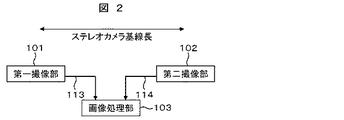
図2は、2つの撮像部を持つ車載カメラ装置、つまりステレオカメラの画像データの伝送を示す図である。 FIG. 2 is a diagram illustrating transmission of image data of an in-vehicle camera device having two imaging units, that is, a stereo camera.
第一撮像部101と第二撮像部102で撮像した画像データは、画像データ信号やクロック信号,画像の同期信号と一緒に信号線113と信号線114によって画像処理部103に伝送されるが、この伝送経路は、図2に示す基線長(第一撮像部101と第二撮像部102間の長さ)と同じ程度配線される。ステレオカメラの基線長は約20cm〜100cm程度を設計する場合が多く、それだけ、信号線113と信号線114の伝送経路が長くなる。
The image data captured by the
さらに、図2の信号線113と信号線114の伝送経路から分かるように伝送経路が、擬似的なダイポールのアンテナを形成してしまい、信号線113と信号線114のノイズが擬似的なダイポールのアンテナを経由して不要輻射ノイズとして出てしまう。
Further, as can be seen from the transmission path of the
そのため、第一撮像部101と第二撮像部102で撮像した画像データ信号,クロック信号,画像の同期信号が伝送される信号線113と信号線114の時間的タイミングをずらすことで、基板全体の、単位時間当たりの電流変化量di/dtを抑えることができるため、不要輻射が抑制できる。
Therefore, by shifting the timings of the
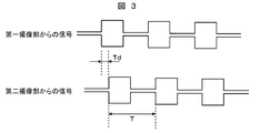
図1に示す画像制御部100は、制御線111と制御線112を使って、第一撮像部101と第二撮像部102で撮像した画像データを画像処理部103へ転送するタイミングを伝送タイミング制御信号線115と伝送タイミング制御信号線116を用いて制御して、第一撮像部101と第二撮像部102で撮像した画像データ信号,クロック信号,画像の同期信号が伝送される信号線113と信号線114のタイミングをずらすことが可能である。信号線113と信号線114のタイミングをTdずらした波形を図3に示す。
The image control unit 100 illustrated in FIG. 1 uses a control line 111 and a
図3は、第一撮像部101と第二撮像部102から画像処理部103に信号線113と信号線114を介して伝送される信号(画像データ信号,クロック信号,画像の同期信号)をずらした波形図であり、信号線113と信号線114は、LVDS(Low Voltage Differencial Signaling)のような2線式のシリアル差動通信を用いた場合を示す。信号線113と信号線114は、画像データ信号,クロック信号,画像の同期信号がシリアルの信号として纏められ伝送される。
FIG. 3 shows the shift of signals (image data signal, clock signal, image synchronization signal) transmitted from the
図3に示すように、第一撮像部101から信号線113を介して画像処理部103に送られる信号と第二撮像部102から信号線114を介して画像処理部103へ送られる信号の2つの信号波形(1周期Tの波形)を予め定めた時間Tdの間隔だけずらすことで、時間的な同時スイッチングのノイズを減らすことが可能となる。そのため、不要輻射ノイズを減らすことが可能となる。
As shown in FIG. 3, two of the signal sent from the
図4は、第一撮像部101と第二撮像部102から画像処理部103に伝送される信号線113と信号線114の位相を180度ずらした波形図である。
FIG. 4 is a waveform diagram in which the phases of the
図4のように、第一撮像部101と第二撮像部102から画像処理部103に伝送される信号線113と信号線114の位相を予め定めた時間Td=180度ずらすことで、信号を駆動するドライバ側のスイッチング電流を相殺できるメリットがある。
As shown in FIG. 4, the signal is transmitted by shifting the phase of the
また、図3や図4に示すように、信号をずらす時間Tdは、信号の波形周期をTとすると、|Td|<Tが望ましい。これは、ステレオカメラの視差計算を行う上で、左右の画像の同期がずれ過ぎると、後段の処理に遅延が生じてしまうためである。 As shown in FIGS. 3 and 4, the time Td for shifting the signal is preferably | Td | <T, where T is the waveform period of the signal. This is because, when the parallax calculation of the stereo camera is performed, if the left and right images are too out of synchronization, the subsequent processing will be delayed.
一般に、周期Tに対して、受信側のICのセットアップ/ホールド時間や、波形の立上り/立下りの鈍り等の遅れ時間を考慮すると、|Td|<T−遅れ時間(数nsec〜数十nsec)程度の範囲で設定することが望ましい。このように設定すれば、信号をずらしたとしても確実にデータが取れる。 In general, when taking into account the delay time such as the setup / hold time of the receiving IC and the rise / fall of the waveform with respect to the period T, | Td | <T−delay time (several nsec to several tens of nsec) ) It is desirable to set within a range. By setting in this way, data can be obtained reliably even if the signal is shifted.
何らかのEMIノイズを受けて左右の画像の同期がずれ過ぎた場合は、図1の画像処理部103が同期ずれを検出できるように内部ロジックを組むことで、画像処理部103が認識部104に同期が取れていない画像であることを知らせ、車両制御部105は車両の制御を停止することができるし、画像処理部103が画像制御部100に同期が取れていない画像であることを知らせ、伝送タイミング制御信号線115と伝送タイミング制御信号線116を伝送する伝送タイミング制御信号のタイミングを微調整できるようなフィードバック系を構築することも可能である。
If the left and right images are too out of sync due to some EMI noise, the
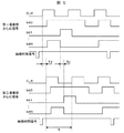
図5は、第一撮像部101と第二撮像部102から画像処理部103に信号線113と信号線114を介して伝送される信号をずらした波形図であり、信号線113と信号線114は、クロック信号(CLK),画像データ信号(bit0,bit1…bitN),画像同期信号がパラレルになったパラレル通信を用いた場合を示す。
FIG. 5 is a waveform diagram in which signals transmitted from the
特にパラレル通信の場合、画像データ信号が伝送される信号線が複数あることが多く(バス幅が大きい場合はbitの本数も増える)、同時スイッチング時の電流変化di/dtが大きくなりやすい。そのため、不要輻射ノイズが問題になりやすい。 In particular, in the case of parallel communication, there are often a plurality of signal lines through which image data signals are transmitted (when the bus width is large, the number of bits increases), and the current change di / dt at the time of simultaneous switching tends to increase. Therefore, unnecessary radiation noise tends to be a problem.
図5に示すようにパラレル通信は、クロック信号(CLK)と画像データ信号(各bit)と画像同期信号がそれぞれ伝送される複数の通信線として存在する。通常、第一撮像部101及び第二撮像部102側から、クロック信号(CLK)に基づいて画像データ信号(bit0〜bitN)と画像同期信号が出力される。クロック信号(CLK)と画像データ信号(bit0〜bitN)及び画像同期信号は、送信するICやドライバ回路などで予め決められた時間ずれており、画像処理部103などの受信側では、クロックの立ち上がりエッジ又は立下りエッジで画像データ信号が伝送される信号線に流れているデータをラッチする。画像同期信号は画面の縦と横の区切りを示す信号であり、特定のタイミングでパルスが発行される。
As shown in FIG. 5, parallel communication exists as a plurality of communication lines through which a clock signal (CLK), an image data signal (each bit), and an image synchronization signal are transmitted. Usually, an image data signal (bit 0 to bit N) and an image synchronization signal are output from the
図5に示すように第一撮像部101からの画像処理部103に信号線113を介して送られる信号(クロック信号や画像データ信号)と第二撮像部102から画像処理部103へ信号線114を介して送られる信号(クロック信号,画像データ信号,画像同期信号)の信号波形をずらすことで、時間的な同時スイッチングのノイズを減らすことが可能となる。そのため、不要輻射ノイズを減らすことが可能となる。
As shown in FIG. 5, a signal (clock signal or image data signal) sent from the
図5では、クロック信号と画像データ信号と画像同期信号が、信号線113の信号と信号線114の信号とで、予め定めた時間Tdずれている状態が示されている。
FIG. 5 shows a state in which the clock signal, the image data signal, and the image synchronization signal are shifted by a predetermined time Td between the signal on the
図6は、第一撮像部101と第二撮像部102から画像処理部103に伝送される信号線113と信号線114の位相を180度ずらした波形図である。
FIG. 6 is a waveform diagram in which the phases of the
図6のように、第一撮像部101と第二撮像部102から画像処理部103に伝送される信号線113と信号線114の位相をTd=180度ずらすことで、信号を駆動するドライバ側のスイッチング電流を相殺できるメリットがある。
As shown in FIG. 6, the driver side that drives the signal by shifting the phase of the
また、図5や図6に示すように、信号をずらす時間Tdは、信号の波形周期をTとすると、|Td|<Tが望ましい。これは、ステレオカメラの視差計算を行う上で、左右の画像の同期がずれ過ぎると、後段の処理に遅延が生じてしまうためである。 Further, as shown in FIGS. 5 and 6, the time Td for shifting the signal is preferably | Td | <T, where T is the waveform period of the signal. This is because, when the parallax calculation of the stereo camera is performed, if the left and right images are too out of synchronization, the subsequent processing will be delayed.
また、シリアル通信と同様に、一般に、周期Tに対して、受信側のICのセットアップ/ホールド時間や、波形の立上り/立下りの鈍り等の遅れ時間を考慮すると、|Td|<T−遅れ時間(数nsec〜数十nsec)程度の範囲で設定することが望ましい。このように設定すれば、信号をずらしたとしても確実にデータが取れる。 Similarly to serial communication, in general, when taking into account the delay time such as the setup / hold time of the receiving IC and the rise / fall of the waveform with respect to the period T, | Td | <T−delay It is desirable to set in the range of time (several nsec to several tens of nsec). By setting in this way, data can be obtained reliably even if the signal is shifted.
何らかのEMIノイズを受けて左右の画像の同期がずれ過ぎた場合は、図1の画像処理部103が同期ずれを検出できるように内部ロジックを組むことで、画像処理部103が認識部104に同期が取れていない画像であることを知らせ、車両制御部105は車両の制御を停止することができるし、画像処理部103が画像制御部100に同期が取れていない画像であることを知らせ、伝送タイミング制御信号線115と116を微調整できるようなフィードバック系を構築することも可能である。
If the left and right images are too out of sync due to some EMI noise, the
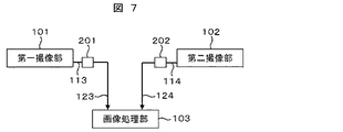
図7は、第一撮像部101と第二撮像部102から画像処理部103に伝送される信号線113(第一信号線)と信号線114(第二信号線)に回路素子201と回路素子202を入れた場合の図である。
FIG. 7 illustrates a
通常、第一撮像部101と第二撮像部102から画像処理部103に伝送される信号線113と信号線114には、信号品質を保つ(信号反射を抑制する)ために、回路素子201と回路素子202を入れることが多い。一般に、回路素子201と回路素子202は、ダンピング抵抗、又は、フェライトビーズ、又は、コイル、又は、コンデンサ、又は、バッファ回路が挿入されることが多い。
Usually, the
第一撮像部101と第二撮像部102から画像処理部103に伝送される信号線113と信号線114の信号タイミングを制御してずらすことができないシステムにおいても、意図的に回路素子201の定数と回路素子202の定数を変えることで、回路素子201と回路素子202を通過後の信号線123(第三信号線)と信号線124(第四信号線)の波形の特性を変化させて信号タイミングをずらすことができる。
Even in a system in which the signal timing of the
図8は、第一撮像部101と第二撮像部102から画像処理部103に伝送される信号線113と信号線114にそれぞれ異なる定数の回路素子201と回路素子202を入れた場合を示しており、信号線113と信号線114は、LVDSのような2線式のシリアル差動通信を用いた場合を示す。
FIG. 8 shows a case where
第一撮像部101から画像処理部103に伝送される信号が信号線113に入れた回路素子201を通過した後の信号線123を伝送する信号は、予め定めた時間Td1だけ時間がずれる。同様に、第二撮像部102から画像処理部103に伝送される信号が信号線114に入れた回路素子202を通過した後の信号線124を伝送する信号は、予め定めた時間Td2だけ時間がずれる。
The signal transmitted from the
この結果、信号線123と信号線124を伝送する信号は予め決められた時間Td3だけずれることになり、時間的な同時スイッチングのノイズを減らすことが可能となる。そのため、不要輻射ノイズを減らすことが可能となる。
As a result, the signals transmitted through the
図9は、第一撮像部101と第二撮像部102から画像処理部103に信号線113と信号線114を介して伝送される信号をずらした波形図であり、信号線113と信号線114は、クロック信号CLK,画像データ信号,画像同期信号がパラレルになったパラレル通信を用いた場合を示す。
FIG. 9 is a waveform diagram in which signals transmitted from the
特にパラレル通信の場合、画像データ信号が伝送される信号線が複数あることが多く(バス幅が大きい場合はbitの本数も増える)、同時スイッチング時の電流変化di/dtが大きくなりやすい。そのため、不要輻射ノイズが問題になりやすい。 In particular, in the case of parallel communication, there are often a plurality of signal lines through which image data signals are transmitted (when the bus width is large, the number of bits increases), and the current change di / dt at the time of simultaneous switching tends to increase. Therefore, unnecessary radiation noise tends to be a problem.
第一撮像部101から画像処理部103に伝送される信号が信号線113に入れた回路素子201を通過した後の信号線123を伝送する信号(クロック信号,画像データ信号,画像同期信号)は、信号線113(クロック信号,画像データ信号,画像同期信号)に対して予め決められた時間Td1だけ時間がずれる。
A signal (clock signal, image data signal, image synchronization signal) transmitted through the
同様に、第二撮像部102から画像処理部103に伝送される信号が信号線114に入れた回路素子202を通過した後の信号線124を伝送する信号(クロック信号,画像データ信号,画像同期信号)は、信号線114を伝送する信号(クロック信号,画像データ信号,画像同期信号)に対して予め決められた時間Td2だけ時間がずれる。
Similarly, a signal (clock signal, image data signal, image synchronization) transmitted through the
この結果、信号線123と信号線124を伝送する信号は予め決められた時間Td3だけずれることになり、時間的な同時スイッチングのノイズを減らすことが可能となる。そのため、不要輻射ノイズを減らすことが可能となる。
As a result, the signals transmitted through the
以上、詳細に説明したように、本発明によれば、2つの撮像部を持つ車載カメラ装置において、2つの撮像部からの送信される画像データ信号,クロック信号,画像同期信号を画像処理部103へ伝送する時に発生する大きな不要輻射ノイズを低コストで低減することができる。
As described above in detail, according to the present invention, in the in-vehicle camera device having two imaging units, the image data signal, the clock signal, and the image synchronization signal transmitted from the two imaging units are transmitted to the
100 画像制御部
101 第一撮像部
102 第二撮像部
103 画像処理部
104 認識部
105 車両制御部
111,112 制御線
113,114 信号線
201,202 回路素子
DESCRIPTION OF SYMBOLS 100
Claims (20)
画像を撮像して画像データ信号を出力する第二撮像部と、
前記第一撮像部及び前記第二撮像部の撮像タイミングを制御する撮像タイミング信号を前記第一撮像部及び前記第二撮像部に出力し、前記第一撮像部及び前記第二撮像部から出力する信号の伝送タイミングを制御する伝送タイミング制御信号を前記第一撮像部及び前記第二撮像部に出力する画像制御部と、
前記第一撮像部及び前記第二撮像部から出力された前記信号を画像処理する画像処理部と、を有し、
前記画像制御部は、前記伝送タイミング制御信号に基づいて、前記第一撮像部から前記画像処理部へ前記信号を出力するタイミングと、前記第二撮像部から前記画像処理部へ前記信号を出力するタイミングとを、時間的にずらす車載カメラ装置。 A first imaging unit that captures an image and outputs an image data signal;
A second imaging unit that captures an image and outputs an image data signal;
An imaging timing signal for controlling imaging timing of the first imaging unit and the second imaging unit is output to the first imaging unit and the second imaging unit, and is output from the first imaging unit and the second imaging unit. An image control unit for outputting a transmission timing control signal for controlling the transmission timing of the signal to the first imaging unit and the second imaging unit;
An image processing unit that performs image processing on the signal output from the first imaging unit and the second imaging unit;
The image control unit outputs the signal from the first imaging unit to the image processing unit and outputs the signal from the second imaging unit to the image processing unit based on the transmission timing control signal. An in-vehicle camera device that shifts the timing in time.
前記第一撮像部及び前記第二撮像部から出力する前記信号は、クロック信号,画像データ信号,画像同期信号の少なくとも1つである車載カメラ装置。 The in-vehicle camera device according to claim 1,
The vehicle-mounted camera device, wherein the signal output from the first imaging unit and the second imaging unit is at least one of a clock signal, an image data signal, and an image synchronization signal.
前記第一撮像部と前記第二撮像部は、毎フレーム同時刻に撮像をする車載カメラ装置。 The in-vehicle camera device according to claim 1,
The first imaging unit and the second imaging unit are in-vehicle camera devices that capture images at the same time every frame.
前記第一撮像部と前記画像制御部間で前記撮像タイミング信号が伝送される第一制御線と、
前記第二撮像部と前記画像制御部間で前記撮像タイミング信号が伝送される第二制御線と、と有する車載カメラ装置。 The in-vehicle camera device according to claim 1,
A first control line through which the imaging timing signal is transmitted between the first imaging unit and the image control unit;
A vehicle-mounted camera device comprising: a second control line through which the imaging timing signal is transmitted between the second imaging unit and the image control unit.
前記第一撮像部と前記画像制御部間で前記伝送タイミング制御信号が伝送される第一伝送タイミング制御信号線と、
前記第二撮像部と前記画像制御部間で前記伝送タイミング制御信号が伝送される第二伝送タイミング制御信号線と、と有する車載カメラ装置。 The in-vehicle camera device according to claim 1,
A first transmission timing control signal line through which the transmission timing control signal is transmitted between the first imaging unit and the image control unit;
And a second transmission timing control signal line through which the transmission timing control signal is transmitted between the second imaging unit and the image control unit.
前記第一撮像部と前記画像処理部間で前記信号が伝送される第一信号線と、
前記第二撮像部と前記画像制御部間で前記信号が伝送される第二信号線と、と有する車載カメラ装置。 The in-vehicle camera device according to claim 1,
A first signal line through which the signal is transmitted between the first imaging unit and the image processing unit;
A vehicle-mounted camera device comprising: a second signal line through which the signal is transmitted between the second imaging unit and the image control unit.
前記画像処理部は、前記第一撮像部及び前記第二撮像部で撮像された画像データ信号から視差情報を算出する車載カメラ装置。 The in-vehicle camera device according to claim 1,
The on-vehicle camera device, wherein the image processing unit calculates parallax information from image data signals captured by the first imaging unit and the second imaging unit.
前記画像処理部で画像処理された画像に基づいて認識処理を行う認識部を有する車載カメラ装置。 The in-vehicle camera device according to claim 1,
A vehicle-mounted camera device having a recognition unit that performs recognition processing based on an image that has been image-processed by the image processing unit.
前記認識部で認識処理された認識結果に基づいて車両を制御する車両制御信号を算出して出力する車両制御部を有する車載カメラ装置。 The in-vehicle camera device according to claim 8,
An in-vehicle camera device having a vehicle control unit that calculates and outputs a vehicle control signal for controlling a vehicle based on a recognition result subjected to recognition processing by the recognition unit.
画像を撮像して画像データ信号を出力する第二撮像部と、
前記第一撮像部及び前記第二撮像部の撮像タイミングを制御する撮像タイミング信号を前記第一撮像部及び前記第二撮像部に出力し、前記第一撮像部及び前記第二撮像部から出力する信号の伝送タイミングを制御する伝送タイミング制御信号を前記第一撮像部及び前記第二撮像部に出力する画像制御部と、
前記第一撮像部及び前記第二撮像部から出力された前記信号を画像処理する画像処理部と、
前記第一撮像部と前記画像処理部間に設けられた第一回路素子と、
前記第二撮像部と前記画像制御部間に設けられた第二回路素子と、を有し、
前記第一回路素子の定数と、前記第二回路素子の定数は、異なる車載カメラ装置。 A first imaging unit that captures an image and outputs an image data signal;
A second imaging unit that captures an image and outputs an image data signal;
An imaging timing signal for controlling imaging timing of the first imaging unit and the second imaging unit is output to the first imaging unit and the second imaging unit, and is output from the first imaging unit and the second imaging unit. An image control unit for outputting a transmission timing control signal for controlling the transmission timing of the signal to the first imaging unit and the second imaging unit;
An image processing unit that performs image processing on the signals output from the first imaging unit and the second imaging unit;
A first circuit element provided between the first imaging unit and the image processing unit;
A second circuit element provided between the second imaging unit and the image control unit,
The constant of the first circuit element and the constant of the second circuit element are different on-vehicle camera devices.
前記第一回路素子から前記画像制御部に前記信号が出力されるタイミングと、前記第二回路素子から前記画像制御部に前記信号が出力されるタイミングとは、時間的にずれている車載カメラ装置。 The in-vehicle camera device according to claim 10,
The in-vehicle camera device in which the timing at which the signal is output from the first circuit element to the image control unit and the timing at which the signal is output from the second circuit element to the image control unit are shifted in time. .
前記第一回路素子及び前記第二回路素子は、ダンピング抵抗,フェライトビーズ,コイル,コンデンサ,バッファ回路のいずれかである車載カメラ装置。 The in-vehicle camera device according to claim 10,
The on-vehicle camera device, wherein the first circuit element and the second circuit element are any one of a damping resistor, a ferrite bead, a coil, a capacitor, and a buffer circuit.
前記第一撮像部及び前記第二撮像部から出力する前記信号は、クロック信号,画像データ信号,画像同期信号の少なくとも1つである車載カメラ装置。 The in-vehicle camera device according to claim 10,
The vehicle-mounted camera device, wherein the signal output from the first imaging unit and the second imaging unit is at least one of a clock signal, an image data signal, and an image synchronization signal.
前記第一撮像部と前記第二撮像部は、毎フレーム同時刻に撮像をする車載カメラ装置。 The in-vehicle camera device according to claim 10,
The first imaging unit and the second imaging unit are in-vehicle camera devices that capture images at the same time every frame.
前記第一撮像部と前記画像制御部間で前記撮像タイミング信号が伝送される第一制御線と、
前記第二撮像部と前記画像制御部間で前記撮像タイミング信号が伝送される第二制御線と、と有する車載カメラ装置。 The in-vehicle camera device according to claim 10,
A first control line through which the imaging timing signal is transmitted between the first imaging unit and the image control unit;
A vehicle-mounted camera device comprising: a second control line through which the imaging timing signal is transmitted between the second imaging unit and the image control unit.
前記第一撮像部と前記画像制御部間で前記伝送タイミング制御信号が伝送される第一伝送タイミング制御信号線と、
前記第二撮像部と前記画像制御部間で前記伝送タイミング制御信号が伝送される第二伝送タイミング制御信号線と、と有する車載カメラ装置。 The in-vehicle camera device according to claim 10,
A first transmission timing control signal line through which the transmission timing control signal is transmitted between the first imaging unit and the image control unit;
And a second transmission timing control signal line through which the transmission timing control signal is transmitted between the second imaging unit and the image control unit.
前記第一撮像部と前記第一回路素子間で前記信号が伝送される第一信号線と、
前記第二撮像部と前記第二回路素子間で前記信号が伝送される第二信号線と、
前記第一回路素子と前記画像制御部間で前記信号が伝送される第三信号線と、
前記第二回路素子と前記画像制御部間で前記信号が伝送される第四信号線と、と有する車載カメラ装置。 The in-vehicle camera device according to claim 10,
A first signal line through which the signal is transmitted between the first imaging unit and the first circuit element;
A second signal line through which the signal is transmitted between the second imaging unit and the second circuit element;
A third signal line through which the signal is transmitted between the first circuit element and the image control unit;
A vehicle-mounted camera device comprising: a fourth signal line through which the signal is transmitted between the second circuit element and the image control unit.
前記画像処理部は、前記第一撮像部及び前記第二撮像部で撮像された画像データ信号から視差情報を算出する車載カメラ装置。 The in-vehicle camera device according to claim 10,
The on-vehicle camera device, wherein the image processing unit calculates parallax information from image data signals captured by the first imaging unit and the second imaging unit.
前記画像処理部で画像処理された画像に基づいて認識処理を行う認識部を有する車載カメラ装置。 The in-vehicle camera device according to claim 10,
A vehicle-mounted camera device having a recognition unit that performs recognition processing based on an image that has been image-processed by the image processing unit.
前記認識部で認識処理された認識結果に基づいて車両を制御する車両制御信号を算出して出力する車両制御部を有する車載カメラ装置。 The in-vehicle camera device according to claim 19,
An in-vehicle camera device having a vehicle control unit that calculates and outputs a vehicle control signal for controlling a vehicle based on a recognition result subjected to recognition processing by the recognition unit.
Priority Applications (4)
| Application Number | Priority Date | Filing Date | Title |
|---|---|---|---|
| JP2011047079A JP5433610B2 (en) | 2011-03-04 | 2011-03-04 | In-vehicle camera device |
| US14/001,364 US20130329017A1 (en) | 2011-03-04 | 2012-03-01 | Vehicle-mounted camera device |
| EP12754985.5A EP2683153B1 (en) | 2011-03-04 | 2012-03-01 | Vehicle-mounted camera device |
| PCT/JP2012/055253 WO2012121108A1 (en) | 2011-03-04 | 2012-03-01 | Vehicle-mounted camera device |
Applications Claiming Priority (1)
| Application Number | Priority Date | Filing Date | Title |
|---|---|---|---|
| JP2011047079A JP5433610B2 (en) | 2011-03-04 | 2011-03-04 | In-vehicle camera device |
Publications (3)
| Publication Number | Publication Date |
|---|---|
| JP2012186574A true JP2012186574A (en) | 2012-09-27 |
| JP2012186574A5 JP2012186574A5 (en) | 2013-01-17 |
| JP5433610B2 JP5433610B2 (en) | 2014-03-05 |
Family
ID=46798075
Family Applications (1)
| Application Number | Title | Priority Date | Filing Date |
|---|---|---|---|
| JP2011047079A Active JP5433610B2 (en) | 2011-03-04 | 2011-03-04 | In-vehicle camera device |
Country Status (4)
| Country | Link |
|---|---|
| US (1) | US20130329017A1 (en) |
| EP (1) | EP2683153B1 (en) |
| JP (1) | JP5433610B2 (en) |
| WO (1) | WO2012121108A1 (en) |
Cited By (5)
| Publication number | Priority date | Publication date | Assignee | Title |
|---|---|---|---|---|
| WO2014167918A1 (en) * | 2013-04-09 | 2014-10-16 | 日立オートモティブシステムズ株式会社 | Stereo camera device |
| JP2015171066A (en) * | 2014-03-10 | 2015-09-28 | 富士通株式会社 | Program, processing device, system and method |
| JP2021034783A (en) * | 2019-08-20 | 2021-03-01 | 三菱電機株式会社 | On-vehicle camera device |
| DE112022002245T5 (en) | 2021-07-02 | 2024-03-14 | Hitachi Astemo, Ltd. | IMAGE PROCESSING SYSTEM, IMAGE PROCESSING APPARATUS AND IMAGE PROCESSING METHOD |
| JP7526027B2 (en) | 2020-05-01 | 2024-07-31 | E&Cエンジニアリング株式会社 | Stripline |
Families Citing this family (2)
| Publication number | Priority date | Publication date | Assignee | Title |
|---|---|---|---|---|
| US20150271471A1 (en) * | 2014-03-19 | 2015-09-24 | Htc Corporation | Blocking detection method for camera and electronic apparatus with cameras |
| DE102021132334A1 (en) * | 2021-12-08 | 2023-06-15 | Bayerische Motoren Werke Aktiengesellschaft | Scanning an environment of a vehicle |
Citations (2)
| Publication number | Priority date | Publication date | Assignee | Title |
|---|---|---|---|---|
| JPH11328413A (en) * | 1998-05-14 | 1999-11-30 | Fuji Heavy Ind Ltd | Stereo image processing system |
| JP2007104349A (en) * | 2005-10-05 | 2007-04-19 | Hitachi Ltd | Imaging device |
Family Cites Families (7)
| Publication number | Priority date | Publication date | Assignee | Title |
|---|---|---|---|---|
| JP3321904B2 (en) * | 1993-06-16 | 2002-09-09 | 株式会社日立製作所 | Imaging device |
| JP3830689B2 (en) * | 1999-05-25 | 2006-10-04 | 三菱電機株式会社 | Stereo camera |
| JP3711840B2 (en) | 2000-05-31 | 2005-11-02 | コニカミノルタホールディングス株式会社 | Clock generating device, substrate, image forming apparatus, and clock generating method |
| TW481390U (en) * | 2000-12-15 | 2002-03-21 | Ind Tech Res Inst | Automatic gain adjusting circuit for analog signal |
| JP2006203448A (en) * | 2005-01-19 | 2006-08-03 | Hitachi Ltd | On-vehicle stereoscopic camera device |
| JP4934701B2 (en) * | 2009-06-30 | 2012-05-16 | 株式会社日立製作所 | Stereo image processing apparatus and stereo image processing method |
| JP5365418B2 (en) | 2009-08-27 | 2013-12-11 | 株式会社豊田自動織機 | Weft detection device in jet loom |
-
2011
- 2011-03-04 JP JP2011047079A patent/JP5433610B2/en active Active
-
2012
- 2012-03-01 EP EP12754985.5A patent/EP2683153B1/en active Active
- 2012-03-01 WO PCT/JP2012/055253 patent/WO2012121108A1/en active Application Filing
- 2012-03-01 US US14/001,364 patent/US20130329017A1/en not_active Abandoned
Patent Citations (2)
| Publication number | Priority date | Publication date | Assignee | Title |
|---|---|---|---|---|
| JPH11328413A (en) * | 1998-05-14 | 1999-11-30 | Fuji Heavy Ind Ltd | Stereo image processing system |
| JP2007104349A (en) * | 2005-10-05 | 2007-04-19 | Hitachi Ltd | Imaging device |
Cited By (7)
| Publication number | Priority date | Publication date | Assignee | Title |
|---|---|---|---|---|
| WO2014167918A1 (en) * | 2013-04-09 | 2014-10-16 | 日立オートモティブシステムズ株式会社 | Stereo camera device |
| JP5942038B2 (en) * | 2013-04-09 | 2016-06-29 | 日立オートモティブシステムズ株式会社 | Stereo camera device |
| US9479756B2 (en) | 2013-04-09 | 2016-10-25 | Hitachi Automotive Systems, Ltd. | Stereo camera device |
| JP2015171066A (en) * | 2014-03-10 | 2015-09-28 | 富士通株式会社 | Program, processing device, system and method |
| JP2021034783A (en) * | 2019-08-20 | 2021-03-01 | 三菱電機株式会社 | On-vehicle camera device |
| JP7526027B2 (en) | 2020-05-01 | 2024-07-31 | E&Cエンジニアリング株式会社 | Stripline |
| DE112022002245T5 (en) | 2021-07-02 | 2024-03-14 | Hitachi Astemo, Ltd. | IMAGE PROCESSING SYSTEM, IMAGE PROCESSING APPARATUS AND IMAGE PROCESSING METHOD |
Also Published As
| Publication number | Publication date |
|---|---|
| EP2683153B1 (en) | 2019-10-16 |
| JP5433610B2 (en) | 2014-03-05 |
| WO2012121108A1 (en) | 2012-09-13 |
| US20130329017A1 (en) | 2013-12-12 |
| EP2683153A4 (en) | 2015-05-06 |
| EP2683153A1 (en) | 2014-01-08 |
Similar Documents
| Publication | Publication Date | Title |
|---|---|---|
| JP5433610B2 (en) | In-vehicle camera device | |
| US10033989B2 (en) | Synchronization controller for multi-sensor camera device and related synchronization method | |
| CN111866304B (en) | Bidirectional synchronous camera, camera system including the same, and method of operating the camera system | |
| US9681045B2 (en) | Systems and methods for generating a panoramic image | |
| US9491495B2 (en) | Method and apparatus for providing input to a camera serial interface transmitter | |
| JP5568458B2 (en) | Stereo camera device | |
| JP5784382B2 (en) | Electronic endoscope device | |
| EP3657776A1 (en) | Analog-digital converter, solid-state imaging element, and control method for analog-digital converter | |
| CN104918003A (en) | Multiple camera synchronization system | |
| JP6660751B2 (en) | Imaging device | |
| JP5924370B2 (en) | Video display device, video switching device, and video display method | |
| US20130329127A1 (en) | Image pickup apparatus | |
| JP2012186574A5 (en) | ||
| KR102493027B1 (en) | Imaging device, driving method thereof, and electronic device | |
| JP2019102889A (en) | Camera system | |
| WO2018025607A1 (en) | On-board camera device, on-board camera adjustment device, and on-board camera adjustment system | |
| US11470233B2 (en) | Multi-camera synchronization through receiver hub back channel | |
| US20090153675A1 (en) | Image Transmitting Apparatus and Wireless Image Receiving Apparatus | |
| CN113661700B (en) | Image forming apparatus and image forming method | |
| CN115277982A (en) | Synchronous exposure processing method, device and storage medium | |
| KR101539544B1 (en) | Method and apparatus for exchanging protocol | |
| JP2006325094A (en) | Image processor for vehicle | |
| KR101469446B1 (en) | Synchronization composite system and method for the plural image | |
| JP2004208162A (en) | System and device for transmitting camera video | |
| WO2024171655A1 (en) | Electronic device and control method for electronic device |
Legal Events
| Date | Code | Title | Description |
|---|---|---|---|
| A521 | Request for written amendment filed |
Free format text: JAPANESE INTERMEDIATE CODE: A523 Effective date: 20121122 |
|
| A621 | Written request for application examination |
Free format text: JAPANESE INTERMEDIATE CODE: A621 Effective date: 20121122 |
|
| A521 | Request for written amendment filed |
Free format text: JAPANESE INTERMEDIATE CODE: A523 Effective date: 20121122 |
|
| A131 | Notification of reasons for refusal |
Free format text: JAPANESE INTERMEDIATE CODE: A131 Effective date: 20130709 |
|
| A521 | Request for written amendment filed |
Free format text: JAPANESE INTERMEDIATE CODE: A523 Effective date: 20130909 |
|
| TRDD | Decision of grant or rejection written | ||
| A01 | Written decision to grant a patent or to grant a registration (utility model) |
Free format text: JAPANESE INTERMEDIATE CODE: A01 Effective date: 20131112 |
|
| A61 | First payment of annual fees (during grant procedure) |
Free format text: JAPANESE INTERMEDIATE CODE: A61 Effective date: 20131209 |
|
| R150 | Certificate of patent or registration of utility model |
Ref document number: 5433610 Country of ref document: JP Free format text: JAPANESE INTERMEDIATE CODE: R150 |
|
| S533 | Written request for registration of change of name |
Free format text: JAPANESE INTERMEDIATE CODE: R313533 |
|
| R350 | Written notification of registration of transfer |
Free format text: JAPANESE INTERMEDIATE CODE: R350 |
|
| R250 | Receipt of annual fees |
Free format text: JAPANESE INTERMEDIATE CODE: R250 |