JP2012183585A - Fixed metal flange and method of producing the same - Google Patents
Fixed metal flange and method of producing the same Download PDFInfo
- Publication number
- JP2012183585A JP2012183585A JP2012033477A JP2012033477A JP2012183585A JP 2012183585 A JP2012183585 A JP 2012183585A JP 2012033477 A JP2012033477 A JP 2012033477A JP 2012033477 A JP2012033477 A JP 2012033477A JP 2012183585 A JP2012183585 A JP 2012183585A
- Authority
- JP
- Japan
- Prior art keywords
- metal
- article
- flanged
- brazing compound
- brazing
- Prior art date
- Legal status (The legal status is an assumption and is not a legal conclusion. Google has not performed a legal analysis and makes no representation as to the accuracy of the status listed.)
- Pending
Links
Images


Classifications
-
- B—PERFORMING OPERATIONS; TRANSPORTING
- B21—MECHANICAL METAL-WORKING WITHOUT ESSENTIALLY REMOVING MATERIAL; PUNCHING METAL
- B21D—WORKING OR PROCESSING OF SHEET METAL OR METAL TUBES, RODS OR PROFILES WITHOUT ESSENTIALLY REMOVING MATERIAL; PUNCHING METAL
- B21D41/00—Application of procedures in order to alter the diameter of tube ends
- B21D41/02—Enlarging
-
- B—PERFORMING OPERATIONS; TRANSPORTING
- B23—MACHINE TOOLS; METAL-WORKING NOT OTHERWISE PROVIDED FOR
- B23K—SOLDERING OR UNSOLDERING; WELDING; CLADDING OR PLATING BY SOLDERING OR WELDING; CUTTING BY APPLYING HEAT LOCALLY, e.g. FLAME CUTTING; WORKING BY LASER BEAM
- B23K1/00—Soldering, e.g. brazing, or unsoldering
- B23K1/19—Soldering, e.g. brazing, or unsoldering taking account of the properties of the materials to be soldered
-
- B—PERFORMING OPERATIONS; TRANSPORTING
- B23—MACHINE TOOLS; METAL-WORKING NOT OTHERWISE PROVIDED FOR
- B23K—SOLDERING OR UNSOLDERING; WELDING; CLADDING OR PLATING BY SOLDERING OR WELDING; CUTTING BY APPLYING HEAT LOCALLY, e.g. FLAME CUTTING; WORKING BY LASER BEAM
- B23K3/00—Tools, devices, or special appurtenances for soldering, e.g. brazing, or unsoldering, not specially adapted for particular methods
- B23K3/08—Auxiliary devices therefor
- B23K3/087—Soldering or brazing jigs, fixtures or clamping means
-
- B—PERFORMING OPERATIONS; TRANSPORTING
- B23—MACHINE TOOLS; METAL-WORKING NOT OTHERWISE PROVIDED FOR
- B23K—SOLDERING OR UNSOLDERING; WELDING; CLADDING OR PLATING BY SOLDERING OR WELDING; CUTTING BY APPLYING HEAT LOCALLY, e.g. FLAME CUTTING; WORKING BY LASER BEAM
- B23K35/00—Rods, electrodes, materials, or media, for use in soldering, welding, or cutting
- B23K35/02—Rods, electrodes, materials, or media, for use in soldering, welding, or cutting characterised by mechanical features, e.g. shape
-
- B—PERFORMING OPERATIONS; TRANSPORTING
- B23—MACHINE TOOLS; METAL-WORKING NOT OTHERWISE PROVIDED FOR
- B23K—SOLDERING OR UNSOLDERING; WELDING; CLADDING OR PLATING BY SOLDERING OR WELDING; CUTTING BY APPLYING HEAT LOCALLY, e.g. FLAME CUTTING; WORKING BY LASER BEAM
- B23K35/00—Rods, electrodes, materials, or media, for use in soldering, welding, or cutting
- B23K35/22—Rods, electrodes, materials, or media, for use in soldering, welding, or cutting characterised by the composition or nature of the material
- B23K35/24—Selection of soldering or welding materials proper
- B23K35/30—Selection of soldering or welding materials proper with the principal constituent melting at less than 1550 degrees C
-
- C—CHEMISTRY; METALLURGY
- C04—CEMENTS; CONCRETE; ARTIFICIAL STONE; CERAMICS; REFRACTORIES
- C04B—LIME, MAGNESIA; SLAG; CEMENTS; COMPOSITIONS THEREOF, e.g. MORTARS, CONCRETE OR LIKE BUILDING MATERIALS; ARTIFICIAL STONE; CERAMICS; REFRACTORIES; TREATMENT OF NATURAL STONE
- C04B37/00—Joining burned ceramic articles with other burned ceramic articles or other articles by heating
- C04B37/02—Joining burned ceramic articles with other burned ceramic articles or other articles by heating with metallic articles
- C04B37/023—Joining burned ceramic articles with other burned ceramic articles or other articles by heating with metallic articles characterised by the interlayer used
- C04B37/026—Joining burned ceramic articles with other burned ceramic articles or other articles by heating with metallic articles characterised by the interlayer used consisting of metals or metal salts
-
- C—CHEMISTRY; METALLURGY
- C21—METALLURGY OF IRON
- C21D—MODIFYING THE PHYSICAL STRUCTURE OF FERROUS METALS; GENERAL DEVICES FOR HEAT TREATMENT OF FERROUS OR NON-FERROUS METALS OR ALLOYS; MAKING METAL MALLEABLE, e.g. BY DECARBURISATION OR TEMPERING
- C21D9/00—Heat treatment, e.g. annealing, hardening, quenching or tempering, adapted for particular articles; Furnaces therefor
- C21D9/50—Heat treatment, e.g. annealing, hardening, quenching or tempering, adapted for particular articles; Furnaces therefor for welded joints
-
- C—CHEMISTRY; METALLURGY
- C04—CEMENTS; CONCRETE; ARTIFICIAL STONE; CERAMICS; REFRACTORIES
- C04B—LIME, MAGNESIA; SLAG; CEMENTS; COMPOSITIONS THEREOF, e.g. MORTARS, CONCRETE OR LIKE BUILDING MATERIALS; ARTIFICIAL STONE; CERAMICS; REFRACTORIES; TREATMENT OF NATURAL STONE
- C04B2237/00—Aspects relating to ceramic laminates or to joining of ceramic articles with other articles by heating
- C04B2237/02—Aspects relating to interlayers, e.g. used to join ceramic articles with other articles by heating
- C04B2237/12—Metallic interlayers
- C04B2237/122—Metallic interlayers based on refractory metals
-
- C—CHEMISTRY; METALLURGY
- C04—CEMENTS; CONCRETE; ARTIFICIAL STONE; CERAMICS; REFRACTORIES
- C04B—LIME, MAGNESIA; SLAG; CEMENTS; COMPOSITIONS THEREOF, e.g. MORTARS, CONCRETE OR LIKE BUILDING MATERIALS; ARTIFICIAL STONE; CERAMICS; REFRACTORIES; TREATMENT OF NATURAL STONE
- C04B2237/00—Aspects relating to ceramic laminates or to joining of ceramic articles with other articles by heating
- C04B2237/02—Aspects relating to interlayers, e.g. used to join ceramic articles with other articles by heating
- C04B2237/12—Metallic interlayers
- C04B2237/123—Metallic interlayers based on iron group metals, e.g. steel
-
- C—CHEMISTRY; METALLURGY
- C04—CEMENTS; CONCRETE; ARTIFICIAL STONE; CERAMICS; REFRACTORIES
- C04B—LIME, MAGNESIA; SLAG; CEMENTS; COMPOSITIONS THEREOF, e.g. MORTARS, CONCRETE OR LIKE BUILDING MATERIALS; ARTIFICIAL STONE; CERAMICS; REFRACTORIES; TREATMENT OF NATURAL STONE
- C04B2237/00—Aspects relating to ceramic laminates or to joining of ceramic articles with other articles by heating
- C04B2237/02—Aspects relating to interlayers, e.g. used to join ceramic articles with other articles by heating
- C04B2237/12—Metallic interlayers
- C04B2237/124—Metallic interlayers based on copper
-
- C—CHEMISTRY; METALLURGY
- C04—CEMENTS; CONCRETE; ARTIFICIAL STONE; CERAMICS; REFRACTORIES
- C04B—LIME, MAGNESIA; SLAG; CEMENTS; COMPOSITIONS THEREOF, e.g. MORTARS, CONCRETE OR LIKE BUILDING MATERIALS; ARTIFICIAL STONE; CERAMICS; REFRACTORIES; TREATMENT OF NATURAL STONE
- C04B2237/00—Aspects relating to ceramic laminates or to joining of ceramic articles with other articles by heating
- C04B2237/02—Aspects relating to interlayers, e.g. used to join ceramic articles with other articles by heating
- C04B2237/12—Metallic interlayers
- C04B2237/125—Metallic interlayers based on noble metals, e.g. silver
-
- C—CHEMISTRY; METALLURGY
- C04—CEMENTS; CONCRETE; ARTIFICIAL STONE; CERAMICS; REFRACTORIES
- C04B—LIME, MAGNESIA; SLAG; CEMENTS; COMPOSITIONS THEREOF, e.g. MORTARS, CONCRETE OR LIKE BUILDING MATERIALS; ARTIFICIAL STONE; CERAMICS; REFRACTORIES; TREATMENT OF NATURAL STONE
- C04B2237/00—Aspects relating to ceramic laminates or to joining of ceramic articles with other articles by heating
- C04B2237/30—Composition of layers of ceramic laminates or of ceramic or metallic articles to be joined by heating, e.g. Si substrates
- C04B2237/32—Ceramic
- C04B2237/34—Oxidic
- C04B2237/343—Alumina or aluminates
-
- C—CHEMISTRY; METALLURGY
- C04—CEMENTS; CONCRETE; ARTIFICIAL STONE; CERAMICS; REFRACTORIES
- C04B—LIME, MAGNESIA; SLAG; CEMENTS; COMPOSITIONS THEREOF, e.g. MORTARS, CONCRETE OR LIKE BUILDING MATERIALS; ARTIFICIAL STONE; CERAMICS; REFRACTORIES; TREATMENT OF NATURAL STONE
- C04B2237/00—Aspects relating to ceramic laminates or to joining of ceramic articles with other articles by heating
- C04B2237/30—Composition of layers of ceramic laminates or of ceramic or metallic articles to be joined by heating, e.g. Si substrates
- C04B2237/40—Metallic
- C04B2237/402—Aluminium
-
- C—CHEMISTRY; METALLURGY
- C04—CEMENTS; CONCRETE; ARTIFICIAL STONE; CERAMICS; REFRACTORIES
- C04B—LIME, MAGNESIA; SLAG; CEMENTS; COMPOSITIONS THEREOF, e.g. MORTARS, CONCRETE OR LIKE BUILDING MATERIALS; ARTIFICIAL STONE; CERAMICS; REFRACTORIES; TREATMENT OF NATURAL STONE
- C04B2237/00—Aspects relating to ceramic laminates or to joining of ceramic articles with other articles by heating
- C04B2237/30—Composition of layers of ceramic laminates or of ceramic or metallic articles to be joined by heating, e.g. Si substrates
- C04B2237/40—Metallic
- C04B2237/403—Refractory metals
-
- C—CHEMISTRY; METALLURGY
- C04—CEMENTS; CONCRETE; ARTIFICIAL STONE; CERAMICS; REFRACTORIES
- C04B—LIME, MAGNESIA; SLAG; CEMENTS; COMPOSITIONS THEREOF, e.g. MORTARS, CONCRETE OR LIKE BUILDING MATERIALS; ARTIFICIAL STONE; CERAMICS; REFRACTORIES; TREATMENT OF NATURAL STONE
- C04B2237/00—Aspects relating to ceramic laminates or to joining of ceramic articles with other articles by heating
- C04B2237/30—Composition of layers of ceramic laminates or of ceramic or metallic articles to be joined by heating, e.g. Si substrates
- C04B2237/40—Metallic
- C04B2237/405—Iron metal group, e.g. Co or Ni
- C04B2237/406—Iron, e.g. steel
-
- C—CHEMISTRY; METALLURGY
- C04—CEMENTS; CONCRETE; ARTIFICIAL STONE; CERAMICS; REFRACTORIES
- C04B—LIME, MAGNESIA; SLAG; CEMENTS; COMPOSITIONS THEREOF, e.g. MORTARS, CONCRETE OR LIKE BUILDING MATERIALS; ARTIFICIAL STONE; CERAMICS; REFRACTORIES; TREATMENT OF NATURAL STONE
- C04B2237/00—Aspects relating to ceramic laminates or to joining of ceramic articles with other articles by heating
- C04B2237/30—Composition of layers of ceramic laminates or of ceramic or metallic articles to be joined by heating, e.g. Si substrates
- C04B2237/40—Metallic
- C04B2237/407—Copper
-
- C—CHEMISTRY; METALLURGY
- C04—CEMENTS; CONCRETE; ARTIFICIAL STONE; CERAMICS; REFRACTORIES
- C04B—LIME, MAGNESIA; SLAG; CEMENTS; COMPOSITIONS THEREOF, e.g. MORTARS, CONCRETE OR LIKE BUILDING MATERIALS; ARTIFICIAL STONE; CERAMICS; REFRACTORIES; TREATMENT OF NATURAL STONE
- C04B2237/00—Aspects relating to ceramic laminates or to joining of ceramic articles with other articles by heating
- C04B2237/30—Composition of layers of ceramic laminates or of ceramic or metallic articles to be joined by heating, e.g. Si substrates
- C04B2237/40—Metallic
- C04B2237/408—Noble metals, e.g. palladium, platina or silver
-
- C—CHEMISTRY; METALLURGY
- C04—CEMENTS; CONCRETE; ARTIFICIAL STONE; CERAMICS; REFRACTORIES
- C04B—LIME, MAGNESIA; SLAG; CEMENTS; COMPOSITIONS THEREOF, e.g. MORTARS, CONCRETE OR LIKE BUILDING MATERIALS; ARTIFICIAL STONE; CERAMICS; REFRACTORIES; TREATMENT OF NATURAL STONE
- C04B2237/00—Aspects relating to ceramic laminates or to joining of ceramic articles with other articles by heating
- C04B2237/50—Processing aspects relating to ceramic laminates or to the joining of ceramic articles with other articles by heating
- C04B2237/55—Pre-treatments of a coated or not coated substrate other than oxidation treatment in order to form an active joining layer
-
- C—CHEMISTRY; METALLURGY
- C04—CEMENTS; CONCRETE; ARTIFICIAL STONE; CERAMICS; REFRACTORIES
- C04B—LIME, MAGNESIA; SLAG; CEMENTS; COMPOSITIONS THEREOF, e.g. MORTARS, CONCRETE OR LIKE BUILDING MATERIALS; ARTIFICIAL STONE; CERAMICS; REFRACTORIES; TREATMENT OF NATURAL STONE
- C04B2237/00—Aspects relating to ceramic laminates or to joining of ceramic articles with other articles by heating
- C04B2237/50—Processing aspects relating to ceramic laminates or to the joining of ceramic articles with other articles by heating
- C04B2237/56—Using constraining layers before or during sintering
- C04B2237/564—Using constraining layers before or during sintering made of glass
-
- C—CHEMISTRY; METALLURGY
- C04—CEMENTS; CONCRETE; ARTIFICIAL STONE; CERAMICS; REFRACTORIES
- C04B—LIME, MAGNESIA; SLAG; CEMENTS; COMPOSITIONS THEREOF, e.g. MORTARS, CONCRETE OR LIKE BUILDING MATERIALS; ARTIFICIAL STONE; CERAMICS; REFRACTORIES; TREATMENT OF NATURAL STONE
- C04B2237/00—Aspects relating to ceramic laminates or to joining of ceramic articles with other articles by heating
- C04B2237/50—Processing aspects relating to ceramic laminates or to the joining of ceramic articles with other articles by heating
- C04B2237/56—Using constraining layers before or during sintering
- C04B2237/567—Using constraining layers before or during sintering made of metal
-
- C—CHEMISTRY; METALLURGY
- C04—CEMENTS; CONCRETE; ARTIFICIAL STONE; CERAMICS; REFRACTORIES
- C04B—LIME, MAGNESIA; SLAG; CEMENTS; COMPOSITIONS THEREOF, e.g. MORTARS, CONCRETE OR LIKE BUILDING MATERIALS; ARTIFICIAL STONE; CERAMICS; REFRACTORIES; TREATMENT OF NATURAL STONE
- C04B2237/00—Aspects relating to ceramic laminates or to joining of ceramic articles with other articles by heating
- C04B2237/50—Processing aspects relating to ceramic laminates or to the joining of ceramic articles with other articles by heating
- C04B2237/56—Using constraining layers before or during sintering
- C04B2237/568—Using constraining layers before or during sintering made of non-oxide ceramics
-
- C—CHEMISTRY; METALLURGY
- C04—CEMENTS; CONCRETE; ARTIFICIAL STONE; CERAMICS; REFRACTORIES
- C04B—LIME, MAGNESIA; SLAG; CEMENTS; COMPOSITIONS THEREOF, e.g. MORTARS, CONCRETE OR LIKE BUILDING MATERIALS; ARTIFICIAL STONE; CERAMICS; REFRACTORIES; TREATMENT OF NATURAL STONE
- C04B2237/00—Aspects relating to ceramic laminates or to joining of ceramic articles with other articles by heating
- C04B2237/50—Processing aspects relating to ceramic laminates or to the joining of ceramic articles with other articles by heating
- C04B2237/70—Forming laminates or joined articles comprising layers of a specific, unusual thickness
- C04B2237/704—Forming laminates or joined articles comprising layers of a specific, unusual thickness of one or more of the ceramic layers or articles
-
- C—CHEMISTRY; METALLURGY
- C04—CEMENTS; CONCRETE; ARTIFICIAL STONE; CERAMICS; REFRACTORIES
- C04B—LIME, MAGNESIA; SLAG; CEMENTS; COMPOSITIONS THEREOF, e.g. MORTARS, CONCRETE OR LIKE BUILDING MATERIALS; ARTIFICIAL STONE; CERAMICS; REFRACTORIES; TREATMENT OF NATURAL STONE
- C04B2237/00—Aspects relating to ceramic laminates or to joining of ceramic articles with other articles by heating
- C04B2237/50—Processing aspects relating to ceramic laminates or to the joining of ceramic articles with other articles by heating
- C04B2237/70—Forming laminates or joined articles comprising layers of a specific, unusual thickness
- C04B2237/706—Forming laminates or joined articles comprising layers of a specific, unusual thickness of one or more of the metallic layers or articles
-
- C—CHEMISTRY; METALLURGY
- C04—CEMENTS; CONCRETE; ARTIFICIAL STONE; CERAMICS; REFRACTORIES
- C04B—LIME, MAGNESIA; SLAG; CEMENTS; COMPOSITIONS THEREOF, e.g. MORTARS, CONCRETE OR LIKE BUILDING MATERIALS; ARTIFICIAL STONE; CERAMICS; REFRACTORIES; TREATMENT OF NATURAL STONE
- C04B2237/00—Aspects relating to ceramic laminates or to joining of ceramic articles with other articles by heating
- C04B2237/50—Processing aspects relating to ceramic laminates or to the joining of ceramic articles with other articles by heating
- C04B2237/72—Forming laminates or joined articles comprising at least two interlayers directly next to each other
-
- C—CHEMISTRY; METALLURGY
- C04—CEMENTS; CONCRETE; ARTIFICIAL STONE; CERAMICS; REFRACTORIES
- C04B—LIME, MAGNESIA; SLAG; CEMENTS; COMPOSITIONS THEREOF, e.g. MORTARS, CONCRETE OR LIKE BUILDING MATERIALS; ARTIFICIAL STONE; CERAMICS; REFRACTORIES; TREATMENT OF NATURAL STONE
- C04B2237/00—Aspects relating to ceramic laminates or to joining of ceramic articles with other articles by heating
- C04B2237/50—Processing aspects relating to ceramic laminates or to the joining of ceramic articles with other articles by heating
- C04B2237/76—Forming laminates or joined articles comprising at least one member in the form other than a sheet or disc, e.g. two tubes or a tube and a sheet or disc
- C04B2237/765—Forming laminates or joined articles comprising at least one member in the form other than a sheet or disc, e.g. two tubes or a tube and a sheet or disc at least one member being a tube
-
- C—CHEMISTRY; METALLURGY
- C04—CEMENTS; CONCRETE; ARTIFICIAL STONE; CERAMICS; REFRACTORIES
- C04B—LIME, MAGNESIA; SLAG; CEMENTS; COMPOSITIONS THEREOF, e.g. MORTARS, CONCRETE OR LIKE BUILDING MATERIALS; ARTIFICIAL STONE; CERAMICS; REFRACTORIES; TREATMENT OF NATURAL STONE
- C04B2237/00—Aspects relating to ceramic laminates or to joining of ceramic articles with other articles by heating
- C04B2237/50—Processing aspects relating to ceramic laminates or to the joining of ceramic articles with other articles by heating
- C04B2237/80—Joining the largest surface of one substrate with a smaller surface of the other substrate, e.g. butt joining or forming a T-joint
-
- C—CHEMISTRY; METALLURGY
- C04—CEMENTS; CONCRETE; ARTIFICIAL STONE; CERAMICS; REFRACTORIES
- C04B—LIME, MAGNESIA; SLAG; CEMENTS; COMPOSITIONS THEREOF, e.g. MORTARS, CONCRETE OR LIKE BUILDING MATERIALS; ARTIFICIAL STONE; CERAMICS; REFRACTORIES; TREATMENT OF NATURAL STONE
- C04B2237/00—Aspects relating to ceramic laminates or to joining of ceramic articles with other articles by heating
- C04B2237/50—Processing aspects relating to ceramic laminates or to the joining of ceramic articles with other articles by heating
- C04B2237/88—Joining of two substrates, where a substantial part of the joining material is present outside of the joint, leading to an outside joining of the joint
-
- Y—GENERAL TAGGING OF NEW TECHNOLOGICAL DEVELOPMENTS; GENERAL TAGGING OF CROSS-SECTIONAL TECHNOLOGIES SPANNING OVER SEVERAL SECTIONS OF THE IPC; TECHNICAL SUBJECTS COVERED BY FORMER USPC CROSS-REFERENCE ART COLLECTIONS [XRACs] AND DIGESTS
- Y10—TECHNICAL SUBJECTS COVERED BY FORMER USPC
- Y10T—TECHNICAL SUBJECTS COVERED BY FORMER US CLASSIFICATION
- Y10T428/00—Stock material or miscellaneous articles
- Y10T428/12—All metal or with adjacent metals
- Y10T428/12229—Intermediate article [e.g., blank, etc.]
- Y10T428/12264—Intermediate article [e.g., blank, etc.] having outward flange, gripping means or interlocking feature
-
- Y—GENERAL TAGGING OF NEW TECHNOLOGICAL DEVELOPMENTS; GENERAL TAGGING OF CROSS-SECTIONAL TECHNOLOGIES SPANNING OVER SEVERAL SECTIONS OF THE IPC; TECHNICAL SUBJECTS COVERED BY FORMER USPC CROSS-REFERENCE ART COLLECTIONS [XRACs] AND DIGESTS
- Y10—TECHNICAL SUBJECTS COVERED BY FORMER USPC
- Y10T—TECHNICAL SUBJECTS COVERED BY FORMER US CLASSIFICATION
- Y10T428/00—Stock material or miscellaneous articles
- Y10T428/12—All metal or with adjacent metals
- Y10T428/12333—Helical or with helical component
Abstract
Description
本発明は、高膨張の金属物品を低膨張の材料に接合することができる固定金属フランジを製造する方法に関する。さらに、本発明は、セラミック構成要素に接合されたフランジ付き金属構成要素を含む、フランジ付き金属物品およびフランジ付き物品に関する。 The present invention relates to a method of manufacturing a fixed metal flange capable of joining a high expansion metal article to a low expansion material. The invention further relates to a flanged metal article and a flanged article comprising a flanged metal component bonded to a ceramic component.
異種の材料で作製された2つの構成要素を接合するために現在使用される組立技術の中で、従来の機械的な組立てを見出すことができるが、それは容積、重量、費用の理由からおよび/または動的挙動が不十分であるという理由から不適切であろうとしばしば考えられている。ろう付けの使用は、2つの異種の材料片を一体に組み立てるために知られている。しかし、そのような技術はセラミック構成要素を金属構成要素に接合する際に適用することがしばしば困難である。というのは、2つの材料の熱機械特性および物理化学特性が非常に異なるからである。例えば、セラミックと金属の熱膨張係数が大きく異なることにより、金属構成要素に接合されたセラミック構成要素を含む物品内で望ましくない残留応力を生成することがある。これらの応力は低減された強度、または非密封接合の原因となり、接合破損を引き起こすことがある。 Among the assembly techniques currently used to join two components made of dissimilar materials, traditional mechanical assembly can be found, for reasons of volume, weight, cost and / or Or it is often considered inappropriate because dynamic behavior is insufficient. The use of brazing is known for assembling two dissimilar pieces of material together. However, such techniques are often difficult to apply when joining ceramic components to metal components. This is because the thermomechanical and physicochemical properties of the two materials are very different. For example, large differences in the coefficient of thermal expansion between ceramic and metal can create undesirable residual stresses in articles that include ceramic components joined to metal components. These stresses can result in reduced strength or non-sealing joints and can cause joint failure.
セラミックは一般に脆く、急激な温度変化および他の機械的応力源に耐えることがほとんどできない。金属材料に直接接合されたセラミック構成要素を含む物品を形成するには、一般に使用される接合技術では、両方の材料の熱膨張特性が適切に適合することが必要である。金属対セラミックのろう付け接合の進歩は当分野で知られている。典型的には、そのような手法は、セラミックの熱膨張係数(CTE:coefficient of thermal expansion)に非常に近い熱膨張係数を有する金属構成要素を必要とする。この要求により、使用可能な材料選択は厳密に制限される。CTEが十分に適合した材料は、困難な加工、高い費用、不十分な化学的適合性、不十分な環境抵抗性および加工中の化学的汚染に対する感受性などの望ましくない特性を示すことがある。 Ceramics are generally brittle and can hardly withstand rapid temperature changes and other sources of mechanical stress. To form an article that includes a ceramic component directly bonded to a metallic material, commonly used bonding techniques require that the thermal expansion properties of both materials be adequately matched. Advances in metal-to-ceramic brazing are known in the art. Typically, such approaches require metal components that have a coefficient of thermal expansion that is very close to the coefficient of thermal expansion (CTE) of the ceramic. This requirement severely limits the choice of materials that can be used. Materials that are well suited for CTE may exhibit undesirable properties such as difficult processing, high cost, poor chemical compatibility, poor environmental resistance and susceptibility to chemical contamination during processing.
したがって、セラミックなど脆い低膨張材料を、金属など高強度の高膨張材料に接合することを可能にする新規な技術を発見することが非常に望ましいはずである。さらに、そのような新規な技術が広範囲の金属を広範囲のセラミック材料に接合するために応用可能であることが望ましく、接合されている物品間の熱膨張特性の大きな相違による悪影響が最小になることが望ましいはずである。 Therefore, it would be highly desirable to find a new technique that allows brittle low expansion materials such as ceramics to be joined to high strength high expansion materials such as metals. Furthermore, it is desirable that such new techniques be applicable to join a wide range of metals to a wide range of ceramic materials, minimizing the negative effects of large differences in thermal expansion properties between the joined articles. Should be desirable.
本発明の一態様によれば、フランジ付き金属物品を作成する方法が提供され、その方法は、(a)第1のろう付け化合物を金属物品の第1の部分に付着するステップと、(b)金属物品の第1の部分をある長さの拘束用金属部材で巻くステップと、(c)金属物品、拘束用金属部材および第1のろう付け化合物の組立体を第1のろう付け化合物の固相線温度を超える温度まで加熱して、フランジ付き金属物品を製造するステップとを含み、その方法では、金属物品が熱膨張係数CTE1を有し、拘束用金属部材が熱膨張係数CTE2を有し、CTE1がCTE2よりも大きい。 According to one aspect of the invention, a method of making a flanged metal article is provided, the method comprising: (a) attaching a first brazing compound to a first portion of the metal article; ) Winding a first portion of the metal article with a length of restraining metal member; and (c) assembling the assembly of the metal article, restraining metal member and first brazing compound of the first brazing compound. Heating to a temperature above the solidus temperature to produce a flanged metal article, wherein the metal article has a coefficient of thermal expansion CTE1 and the constraining metal member has a coefficient of thermal expansion CTE2. CTE1 is larger than CTE2.
本発明の別の態様によれば、(a)ある長さの拘束用金属部材を含む金属物品の巻かれた第1の部分と、(b)拘束用金属部材および金属物品の巻かれた第1の部分の面に接触する第1のろう付け化合物とを含むフランジ付き金属物品が提供され、金属物品が熱膨張係数CTE1を有し、拘束用金属部材が熱膨張係数CTE2を有し、CTE1がCTE2よりも大きい。 According to another aspect of the present invention, (a) a wound metal first article having a length of restraining metal member, and (b) a restraining metal member and a metal article wound first. A flanged metal article comprising a first brazing compound in contact with a surface of one portion is provided, wherein the metal article has a coefficient of thermal expansion CTE1, the constraining metal member has a coefficient of thermal expansion CTE2, and CTE1 Is greater than CTE2.
本発明の別の態様によれば、(a)セラミック構成要素に接合されたフランジ付き金属構成要素であって、フランジ付き金属構成要素がモリブデン線で巻かれており、フランジ付き金属構成要素がニッケル、鉄、コバルト、およびクロムの1つまたは複数を含むフランジ付き金属構成要素と、(b)フランジ付き金属構成要素およびモリブデン線の面に接触する第1のろう付け化合物とを含むフランジ付き物品が提供され、フランジ付き金属構成要素が熱膨張係数CTE1を有し、モリブデン線が熱膨張係数CTE2を有し、CTE1がCTE2よりも少なくとも100%大きい。 According to another aspect of the invention, (a) a flanged metal component joined to a ceramic component, wherein the flanged metal component is wound with molybdenum wire and the flanged metal component is nickel. A flanged article comprising a flanged metal component comprising one or more of: iron, cobalt, and chromium; and (b) a first brazing compound that contacts the flanged metal component and the surface of the molybdenum wire. Provided, the flanged metal component has a coefficient of thermal expansion CTE1, the molybdenum wire has a coefficient of thermal expansion CTE2, and CTE1 is at least 100% greater than CTE2.
本発明の別の態様によれば、セラミック構成要素に接合されたフランジ付き金属構成要素を含む物品を作製する方法が提供され、その方法は、(a)第1のろう付け化合物を金属物品の第1の部分に付着するステップと、(b)金属物品の第1の部分をある長さの拘束用金属部材で巻くステップと、(c)金属物品、拘束用金属部材および第1のろう付け化合物の組立体を第1のろう付け化合物の固相線温度を超える温度まで加熱して、フランジ付き金属物品を製造するステップであって、金属物品が熱膨張係数CTE1を有し、拘束用金属部材が熱膨張係数CTE2を有し、CTE1がCTE2よりも大きいステップと、(d)フランジ付き金属物品のフランジ付き部分を第2のろう付け化合物およびセラミック物品に接触させるステップであって、第2のろう付け化合物が金属物品のフランジ付き部分とセラミック物品の間に配置されるようになっているステップと、(e)フランジ付き金属物品、第2のろう付け化合物およびセラミック物品の組立体を第2のろう付け化合物の固相線温度を超える温度まで加熱して、セラミック構成要素に接合されたフランジ付き金属構成要素を含む物品を製造するステップとを含む。 In accordance with another aspect of the present invention, there is provided a method of making an article comprising a flanged metal component joined to a ceramic component, the method comprising: (a) applying a first brazing compound to the metal article. Attaching to the first portion; (b) winding the first portion of the metal article with a length of restraining metal member; and (c) the metal article, restraining metal member and first brazing. Heating the compound assembly to a temperature above the solidus temperature of the first brazing compound to produce a flanged metal article, wherein the metal article has a coefficient of thermal expansion CTE1, and the constraining metal The member has a coefficient of thermal expansion CTE2 and CTE1 is greater than CTE2, and (d) contacting the flanged portion of the flanged metal article with the second brazing compound and the ceramic article. A second brazing compound is disposed between the flanged portion of the metal article and the ceramic article; (e) the flanged metal article, the second brazing compound, and the ceramic article. Heating the assembly to a temperature above the solidus temperature of the second brazing compound to produce an article comprising a flanged metal component joined to the ceramic component.
本発明の他の実施形態、態様、特徴および利点が、以下の詳細な説明、添付の図面および添付の特許請求の範囲から当業者にとって明らかになるであろう。 Other embodiments, aspects, features and advantages of the present invention will become apparent to those skilled in the art from the following detailed description, the accompanying drawings and the appended claims.
以下の詳細な説明が添付の図面を参照して読まれると、本発明のこれらのおよび他の特徴、態様および利点がよりよく理解されるであろう。添付の図面では、図面全体を通して同じ符号が同じ部品を表す。 These and other features, aspects and advantages of the present invention will be better understood when the following detailed description is read with reference to the accompanying drawings, in which: In the accompanying drawings, like reference numerals designate like parts throughout the views.
単数形の「1つの(a)」、「1つの(an)」および「その(the)」は、文脈から明確にそうではないと指示しない限り、複数の参照対象を含む。 The singular forms “a”, “an”, and “the” include plural referents unless the context clearly dictates otherwise.
本明細書で使用されると、「ろう付け化合物」という用語は、例えば、金地金、銀地金およびパラジウム地金などの純粋材料、ならびに例えば、銀−銅ろう付け合金、金−ニッケルろう付け合金および銀−銅−亜鉛ろう付け合金などの多組成ろう付け材料の両方を含む。 As used herein, the term “brazing compound” refers to pure materials such as, for example, gold bullion, silver bullion and palladium bullion, as well as, for example, silver-copper brazing alloys, gold-nickel brazing. Includes both alloys and multi-composition brazing materials such as silver-copper-zinc brazing alloys.
一実施形態では、本発明は、フランジ付き金属物品を作製する方法を提供し、その方法は、(a)第1のろう付け化合物を金属物品の第1の部分に付着するステップと、(b)金属物品の第1の部分をある長さの拘束用金属部材で巻くステップと、(c)金属物品、拘束用金属部材および第1のろう付け化合物の組立体を第1のろう付け化合物の固相線温度を超える温度まで加熱して、フランジ付き金属物品を製造するステップとを含み、その方法では、金属物品が熱膨張係数CTE1を有し、拘束用金属部材が熱膨張係数CTE2を有し、CTE1がCTE2よりも大きい。 In one embodiment, the present invention provides a method of making a flanged metal article, the method comprising: (a) attaching a first brazing compound to a first portion of the metal article; ) Winding a first portion of the metal article with a length of restraining metal member; and (c) assembling the assembly of the metal article, restraining metal member and first brazing compound of the first brazing compound. Heating to a temperature above the solidus temperature to produce a flanged metal article, wherein the metal article has a coefficient of thermal expansion CTE1 and the constraining metal member has a coefficient of thermal expansion CTE2. CTE1 is larger than CTE2.
本発明の方法によって製造されたフランジは、様々な用途に使用され得るが、より低い熱膨張係数(CTE)を有する材料をより高い熱膨張係数を有する材料に接合することが所望されるとき、例えば、金属をセラミックに接合するとき、特に有益である。本発明の方法によって製造されたフランジは、フランジの熱膨張特性が金属物品出発材料に対して拘束用金属部材によって制限されるという意味で、「固定」金属フランジである。 The flange manufactured by the method of the present invention can be used for various applications, but when it is desired to join a material having a lower coefficient of thermal expansion (CTE) to a material having a higher coefficient of thermal expansion, For example, it is particularly beneficial when joining metal to ceramic. The flange produced by the method of the present invention is a “fixed” metal flange in the sense that the thermal expansion properties of the flange are limited by the constraining metal member relative to the metal article starting material.
本発明のフランジ付き金属物品を準備するための出発材料として使用される金属物品は、フランジを形成することが所望される任意の金属物品であってよい。適切な金属物品の制限されない例には、金属パイプ、金属棒、金属板および金属容器が含まれる。言及したように、金属物品は本発明によって提供されるフランジ付き金属物品を準備するための出発点である。金属物品の適切な構築材料の制限されない例には、金、ニッケル、チタニウム、銀、銅、プラチナ、パラジウム、ニオブ、タンタル、モリブデン、合金625、ジルコニウム、コバルト、クロム、ステンレス鋼およびこれらの材料の組合せが含まれる。一実施形態では、フランジ付き金属物品を製造するために使用される金属物品は、ニッケルを含む合金、鉄を含む合金、コバルトを含む合金、銅を含む合金およびアルミニウムを含む合金の少なくとも1つを含む。したがって、一実施形態では、金属物品出発材料はニッケルを含む合金を有する。別の実施形態では、金属物品出発材料は鉄を含む合金を含む。別の実施形態では、金属物品はニッケルおよび鉄を含む合金を含む。いくつかの実施形態では、金属物品はニオブを含む。一実施形態では、金属物品はニオブ基合金から作製される。別の実施形態では、金属物品は本質的にニオブからなる。様々な実施形態では、金属物品は、炭素鋼、ニッケル合金、マルテンサイトステンレス鋼、オーステナイトステンレス鋼、銅合金またはアルミニウム合金を含むことができる。 The metal article used as a starting material for preparing the flanged metal article of the present invention may be any metal article in which it is desired to form a flange. Non-limiting examples of suitable metal articles include metal pipes, metal bars, metal plates and metal containers. As mentioned, the metal article is the starting point for preparing the flanged metal article provided by the present invention. Non-limiting examples of suitable building materials for metal articles include gold, nickel, titanium, silver, copper, platinum, palladium, niobium, tantalum, molybdenum, alloy 625, zirconium, cobalt, chromium, stainless steel and these materials. Combinations are included. In one embodiment, the metal article used to manufacture the flanged metal article comprises at least one of an alloy comprising nickel, an alloy comprising iron, an alloy comprising cobalt, an alloy comprising copper and an alloy comprising aluminum. Including. Thus, in one embodiment, the metal article starting material has an alloy comprising nickel. In another embodiment, the metal article starting material comprises an alloy comprising iron. In another embodiment, the metal article comprises an alloy comprising nickel and iron. In some embodiments, the metal article includes niobium. In one embodiment, the metal article is made from a niobium-based alloy. In another embodiment, the metal article consists essentially of niobium. In various embodiments, the metal article can include carbon steel, nickel alloy, martensitic stainless steel, austenitic stainless steel, copper alloy or aluminum alloy.
いくつかの実施形態では、金属物品は1つまたは複数の超合金を含む。多様な超合金は、当業者に知られており、本発明の1つまたは複数の実施形態による使用に適する。一実施形態では、金属物品は、ニッケル基超合金、鉄基超合金、コバルト基超合金およびそれらの2つ以上の組合せからなる群から選択される1つまたは複数の超合金を含む。ニッケル基超合金は、Astroloy、Hastelloy、INCONEL、Nimonic、Pyromet、Rene、UdimetおよびWaspaloyによって例示される。鉄基超合金は、DiscaloyおよびIncoloyによって例示される。コバルト基超合金は、AirResist、エルジロイ(Elgiloy)、MP35Nおよびステライト(Stellite)によって例示される。 In some embodiments, the metal article includes one or more superalloys. A variety of superalloys are known to those skilled in the art and are suitable for use in accordance with one or more embodiments of the present invention. In one embodiment, the metal article includes one or more superalloys selected from the group consisting of nickel-base superalloys, iron-base superalloys, cobalt-base superalloys, and combinations of two or more thereof. Nickel-based superalloys are exemplified by Astroloy, Hastelloy, INCONEL, Nimonic, Pyromet, Rene, Udimet, and Waspaloy. Iron-base superalloys are exemplified by Discovery and Incoloy. Cobalt-based superalloys are exemplified by AirResist, Elgiloy, MP35N and Stellite.
金属物品は任意の所望の形状を有することができ、例えば、円筒形状、円錐形状、球形状、矩形形状、立方体形状または不規則形状でもよい。いくつかの実施形態では、金属物品は円筒である。一実施形態では、円筒形金属物品は、約0.005インチから約0.10インチの範囲の厚さを有する。具体的な実施形態では、円筒形金属物品は、約0.035インチの厚さを有する。一実施形態では、金属物品はパイプであり、例えば、金属物品はニッケル合金パイプである。別の実施形態では金属物品は棒である。 The metal article can have any desired shape, for example, a cylindrical shape, a conical shape, a spherical shape, a rectangular shape, a cubic shape, or an irregular shape. In some embodiments, the metal article is a cylinder. In one embodiment, the cylindrical metal article has a thickness in the range of about 0.005 inches to about 0.10 inches. In a specific embodiment, the cylindrical metal article has a thickness of about 0.035 inches. In one embodiment, the metal article is a pipe, for example, the metal article is a nickel alloy pipe. In another embodiment, the metal article is a bar.
言及したように、本発明によって提供されるフランジ付き金属物品を準備するための出発点である金属物品は、第1のろう付け化合物が付着され得る第1の部分を有する。一実施形態では、金属物品の第1の部分は端部である。別の実施形態では、金属物品の第1の部分は端部ではない部分、例えばパイプの中央区域である。 As mentioned, the metal article that is the starting point for preparing the flanged metal article provided by the present invention has a first portion to which a first brazing compound can be deposited. In one embodiment, the first portion of the metal article is an end. In another embodiment, the first portion of the metal article is a non-end portion, such as a central area of a pipe.
言及したように、本発明によって提供されるフランジ付き金属物品を準備するための出発材料の1つである第1のろう付け化合物は、金属物品の第1の部分および拘束用金属部材の両方に接触するように配置される。一実施形態では、第1のろう付け化合物は、拘束用金属部材を金属物品の第1の部分の周りに巻く前に、金属物品の第1の部分上に付着される。別の実施形態では、第1のろう付け化合物は、拘束用金属部材を金属物品の第1の部分の周りに巻いた後に金属物品の第1の部分に付着される。 As mentioned, the first brazing compound, one of the starting materials for preparing the flanged metal article provided by the present invention, is applied to both the first part of the metal article and the constraining metal member. Arranged to touch. In one embodiment, the first brazing compound is deposited on the first portion of the metal article prior to wrapping the constraining metal member around the first portion of the metal article. In another embodiment, the first brazing compound is attached to the first portion of the metal article after the constraining metal member is wrapped around the first portion of the metal article.
第1のろう付け化合物は、当業者に知られている様々な要因、例えば、ろう付け性能特性(例えば、ろう付け温度)および費用などに基づき選択されることができる。多様なろう付け化合物が当業者に知られており、単一組成のろう付け化合物、例えば、金、銀、およびパラジウムなどの比較的純粋な金属、ならびに多組成ろう付け化合物、例えば、銀−銅ろう付け合金、銀−亜鉛ろう付け合金、銅−亜鉛ろう付け合金、銀−銅−亜鉛ろう付け合金、銀−銅−亜鉛−カドミウムろう付け合金、銅−リンろう付け合金、銀−銅−リンろう付け合金、金−銀ろう付け合金、金−銅ろう付け合金、金−ニッケルろう付け合金、金−パラジウムろう付け合金、パラジウム基ろう付け合金、ニッケル基ろう付け合金、コバルト基ろう付け合金、アルミニウム基ろう付け合金(例えば、アルミニウム、シリコンろう付け合金)および1つまたは複数の反応性金属構成要素を含む活性ろう付け合金であってよい。具体的な実施形態では、第1のろう付け化合物は比較的純粋な金である。一実施形態では、第1のろう付け化合物は、金基ろう付け化合物、銅基ろう付け化合物、銀基ろう付け化合物、プラチナ基ろう付け化合物、パラジウム基ろう付け化合物、チタニウム基ろう付け化合物、バナジウム基ろう付け化合物、ニッケル基ろう付け化合物およびそれらの組合せからなる群から選択される。いくつかの他の実施形態では、第1のろう付け化合物は、本明細書で時々活性ろう付け合金と言及される、活性ろう付け化合物である。多様なろう付け化合物および活性ろう付け化合物が当業者に知られており、市販で入手可能である。 The first brazing compound can be selected based on various factors known to those skilled in the art, such as brazing performance characteristics (eg, brazing temperature) and cost. A variety of brazing compounds are known to those skilled in the art, including single composition brazing compounds such as relatively pure metals such as gold, silver, and palladium, and multi-composition brazing compounds such as silver-copper. Brazing alloy, silver-zinc brazing alloy, copper-zinc brazing alloy, silver-copper-zinc brazing alloy, silver-copper-zinc-cadmium brazing alloy, copper-phosphorus brazing alloy, silver-copper-phosphorus Brazing alloy, gold-silver brazing alloy, gold-copper brazing alloy, gold-nickel brazing alloy, gold-palladium brazing alloy, palladium based brazing alloy, nickel based brazing alloy, cobalt based brazing alloy, It may be an active brazing alloy comprising an aluminum-based brazing alloy (eg, aluminum, silicon brazing alloy) and one or more reactive metal components. In a specific embodiment, the first brazing compound is relatively pure gold. In one embodiment, the first brazing compound is a gold based brazing compound, a copper based brazing compound, a silver based brazing compound, a platinum based brazing compound, a palladium based brazing compound, a titanium based brazing compound, a vanadium. Selected from the group consisting of a base braze compound, a nickel base braze compound, and combinations thereof. In some other embodiments, the first brazing compound is an active brazing compound, sometimes referred to herein as an active brazing alloy. A wide variety of brazing compounds and active brazing compounds are known to those skilled in the art and are commercially available.
言及したように、ある長さの拘束用金属部材は、第1のろう付け化合物と併せて使用されて、フランジ付き金属物品を形成する。その名前が示すように、拘束用金属部材は、熱処理およびそれに続く冷却の間、金属物品を制約する。限定するわけではないが、拘束用金属部材には、撚線、線条、ワイヤ、多線条ケーブル、線状拘束用鋼帯、小片、テープ、穿孔テープおよび箔が含まれてよい。一実施形態では、拘束用金属部材は単一線条ワイヤである。別の実施形態では、拘束用金属部材は多線条ワイヤである。 As mentioned, a length of restraining metal member is used in conjunction with the first brazing compound to form a flanged metal article. As the name implies, the constraining metal member constrains the metal article during heat treatment and subsequent cooling. Without limitation, the constraining metal member may include stranded wire, wire, wire, multi-wire cable, wire constraining steel strip, strip, tape, perforated tape and foil. In one embodiment, the constraining metal member is a single wire. In another embodiment, the constraining metal member is a multifilament wire.
一実施形態では、拘束用金属部材は長さおよび幅の寸法を有する線状物品であり、高い縦横比を特徴とする。線状というのは、拘束用金属部材が金属物品の周りに巻きやすく、または包みやすいということを意味する。本明細書で使用されると、「縦横比」という用語は、採用される各拘束用金属部材の長さ対幅の比率を指す。例えば、単一線条ワイヤの縦横比は、単一線条ワイヤの長さ対単一線条ワイヤの幅(または厚さ)の比率を指す。いくつかの実施形態では、拘束用金属部材は金属物品の第1の部分の周りに部分的または完全に巻かれる。例えば、拘束用金属部材は金属物品の第1の部分の周りに巻かれたワイヤであってよい。様々な実施形態では、拘束用金属部材は、金属物品の第1の部分の周りに複数のターンを作製することにより金属物品の周りに巻かれる。拘束用金属部材のターン数は、金属物品の大きさ、拘束用金属部材の長さおよび金属物品の熱膨張特性に応じて可変である。いくつかの実施形態では、金属物品は、拘束用金属部材が金属物品の第1の部分の面上に1つまたは複数の層を形成するように拘束用金属部材で巻かれる。いくつかの実施形態では、金属物品は2つ以上の拘束用金属部材で相互に重ねて巻かれて、金属物品上に拘束用金属部材の複数の層を含む組立体を形成することができる。様々な実施形態では、拘束用金属部材の縦横比は、約10から約10,000の範囲である。一実施形態では、拘束用金属部材の縦横比は、約10から約1000の範囲である。別の実施形態では、拘束用金属部材の縦横比は、約10から約100の範囲である。一実施形態では、拘束用金属部材は一定の長さおよび可変の幅(または厚さ)を有し、その場合、拘束用金属部材の縦横比は、拘束用金属部材の長さ対その平均の幅(または厚さ)の比率によって決定することができる。 In one embodiment, the constraining metal member is a linear article having length and width dimensions and is characterized by a high aspect ratio. The term “linear” means that the constraining metal member is easily wound around or wrapped around the metal article. As used herein, the term “aspect ratio” refers to the length to width ratio of each constraining metal member employed. For example, the aspect ratio of a single filament wire refers to the ratio of the length of the single filament wire to the width (or thickness) of the single filament wire. In some embodiments, the constraining metal member is partially or fully wound around the first portion of the metal article. For example, the constraining metal member may be a wire wound around the first portion of the metal article. In various embodiments, the constraining metal member is wound around the metal article by creating a plurality of turns around the first portion of the metal article. The number of turns of the restraining metal member is variable depending on the size of the metal article, the length of the restraining metal member, and the thermal expansion characteristics of the metal article. In some embodiments, the metal article is wrapped with the constraining metal member such that the constraining metal member forms one or more layers on the surface of the first portion of the metal article. In some embodiments, the metal article can be wound on top of each other with two or more restraining metal members to form an assembly that includes multiple layers of restraining metal members on the metal article. In various embodiments, the restraining metal member has an aspect ratio in the range of about 10 to about 10,000. In one embodiment, the restraining metal member has an aspect ratio in the range of about 10 to about 1000. In another embodiment, the constraining metal member has an aspect ratio in the range of about 10 to about 100. In one embodiment, the constraining metal member has a constant length and a variable width (or thickness), wherein the aspect ratio of the constraining metal member is the length of the constraining metal member versus its average. It can be determined by the ratio of width (or thickness).
拘束用金属部材は、低い熱膨張係数および高温度で大きな弾性率を有するように選択されることがある。拘束用金属部材は、加熱の際に金属物品の第1の部分が膨張して拘束用金属部材と密着嵌合ができるような方法で、金属物品の第1の部分の周りに巻かれることができる。様々な実施形態では、製造されたフランジの寸法は、拘束用金属部材が最初に金属物品の周りにどれくらいしっかりと巻かれるかによって制御することができる。金属物品の組立体として、拘束用金属部材およびろう付け化合物は加熱され、金属物品は拘束用金属部材よりも大きく膨張し、言及したように、拘束用金属部材と密着嵌合する。冷却すると、金属物品と拘束用金属部材との密着により、拘束用金属部材と密着嵌合している金属物品の部分および第1のろう付け化合物の収縮が阻止される。言及したように、拘束用金属部材は、典型的には、拘束用金属部材として使用されるために適切に成形され得る(例えば、箔またはワイヤに形成され得る)、比較的低いCTEを有する材料からなる。一実施形態では、拘束用金属部材は、モリブデン、タングステン、シリコン、カーバイド、溶融水晶、黒鉛またはガラスの少なくとも1つを含む。一実施形態では、拘束用金属部材は、ハフニウム部材、ジルコニウム部材、クロム部材、ニッケル部材、鉄部材、モリブデン部材、ニオブ部材およびそれらの2つ以上の組合せからなる群から選択される。本明細書で使用されると、ハフニウム部材、ジルコニウム部材、クロム部材、ニッケル部材、鉄部材、モリブデン部材およびニオブ部材という用語は、1つまたは複数の上記に挙げた要素を含む拘束用金属部材を指す。したがって、ハフニウム部材はハフニウムを含み、ジルコニウム部材はジルコニウムを含み、クロム部材はクロムを含み、ニッケル部材はニッケルを含み、鉄部材は鉄を含み、モリブデン部材はモリブデンを含み、ニオブ部材はニオブを含む。当業者は、拘束用金属部材が元素形態の金属、金属合金、または元素形態の金属とも金属合金とも見なされない金属物質を含むことができることを理解するであろう。具体的な実施形態では、拘束用金属部材はモリブデン部材であり、元素モリブデンを含む。別の実施形態では、拘束用金属部材はモリブデン合金を含むモリブデン部材である。一実施形態では、拘束用金属部材はランタン化モリブデン(lanthanated molybdenum)を含む。ランタン化モリブデンは、他のモリブデン基材料の有益な代替材料になることがある。一実施形態では、拘束用金属部材は約0.875%のLa2O3を含むランタン化モリブデンから構成される。 The constraining metal member may be selected to have a low coefficient of thermal expansion and a high modulus at high temperatures. The restraining metal member may be wound around the first portion of the metal article in such a manner that the first portion of the metal article expands upon heating and can be tightly fitted with the restraining metal member. it can. In various embodiments, the dimensions of the manufactured flange can be controlled by how tightly the constraining metal member is initially wrapped around the metal article. As an assembly of metal articles, the constraining metal member and brazing compound are heated and the metal article expands more than the constraining metal member and, as mentioned, closely fits with the constraining metal member. When cooled, due to the close contact between the metal article and the restraining metal member, shrinkage of the portion of the metal article and the first brazing compound that are in close contact with the restraining metal member is prevented. As mentioned, the constraining metal member is typically a material having a relatively low CTE that can be suitably shaped (eg, formed into a foil or wire) for use as a constraining metal member. Consists of. In one embodiment, the constraining metal member includes at least one of molybdenum, tungsten, silicon, carbide, fused quartz, graphite, or glass. In one embodiment, the constraining metal member is selected from the group consisting of a hafnium member, a zirconium member, a chromium member, a nickel member, an iron member, a molybdenum member, a niobium member, and combinations of two or more thereof. As used herein, the terms hafnium member, zirconium member, chromium member, nickel member, iron member, molybdenum member, and niobium member refer to a constraining metal member that includes one or more of the elements listed above. Point to. Thus, the hafnium member includes hafnium, the zirconium member includes zirconium, the chromium member includes chromium, the nickel member includes nickel, the iron member includes iron, the molybdenum member includes molybdenum, and the niobium member includes niobium. . One skilled in the art will appreciate that the constraining metal member can include elemental form metals, metal alloys, or metal materials that are not considered elemental forms or metal alloys. In a specific embodiment, the constraining metal member is a molybdenum member and includes elemental molybdenum. In another embodiment, the constraining metal member is a molybdenum member that includes a molybdenum alloy. In one embodiment, the constraining metal member comprises lanthanated molybdenum. Molybdenum lanthanide can be a useful alternative to other molybdenum-based materials. In one embodiment, the constraining metal member is composed of molybdenum lanthanum containing about 0.875% La 2 O 3 .
具体的な実施形態では、拘束用金属部材はモリブデン線である。モリブデンは、金属物品出発材料の構築材料として適切な様々なニッケル基超合金の熱膨張係数よりも低い熱膨張係数を有する。いくつかの例示的金属材料のCTEは以下の表1に示される。表から分かるように、モリブデン金属は、拘束用金属部材として使用するのに適しているが、金属物品として使用するのに適する材料、インコネル625(INCONEL625)よりもかなり低いCTEを有する。 In a specific embodiment, the constraining metal member is a molybdenum wire. Molybdenum has a coefficient of thermal expansion that is lower than that of various nickel-based superalloys suitable as building materials for metal article starting materials. The CTEs for some exemplary metallic materials are shown in Table 1 below. As can be seen from the table, molybdenum metal is suitable for use as a constraining metal member, but has a significantly lower CTE than a material suitable for use as a metal article, INCONEL 625.

一実施形態では、薄いモリブデン線をニッケル合金パイプ(金属物品の第1の部分)の端部の周りに複数回巻くことができ、ニッケル合金パイプの外側面上には、金ろう付け化合物がパイプの外側面およびモリブデン線の両方に接触するように、金ろう付け化合物が配置される。次いでこの組立体は加熱され、続いて冷却されて、フランジ付き金属物品を製造する。別の実施形態では、薄いモリブデン線をニッケル合金パイプ上に巻くことができ、金ろう付け化合物がモリブデン線と接触するように、金ろう付け化合物はパイプの巻かれた部分に付着される。次いでこの組立体は加熱され、続いて冷却されて、フランジ付き金属物品を製造することができる。 In one embodiment, a thin molybdenum wire can be wound multiple times around the end of a nickel alloy pipe (the first part of the metal article), and on the outer surface of the nickel alloy pipe, a gold brazing compound is piped. A gold brazing compound is placed in contact with both the outer surface of the metal and the molybdenum wire. The assembly is then heated and subsequently cooled to produce a flanged metal article. In another embodiment, a thin molybdenum wire can be wound onto a nickel alloy pipe, and the gold brazing compound is attached to the wound portion of the pipe so that the gold brazing compound is in contact with the molybdenum wire. The assembly can then be heated and subsequently cooled to produce a flanged metal article.
拘束用金属部材の幅は、製造されるフランジの大きさおよび形状を制御するために金属物品の膨張特性および収縮特性に応じて適切に調整することができる。いくつかの実施形態では、拘束用金属部材は比較的均一の寸法のワイヤであり、約0.005インチから約0.025インチの範囲の直径を有し、「薄い」ワイヤを例示する。具体的な実施形態では、拘束用金属部材の直径は約0.012インチである。例えば、拘束用金属部材は約0.005インチから約0.025インチの範囲の直径を有するモリブデン線であってよく、具体的な実施形態では、拘束用金属部材は約0.012インチの直径を有するモリブデン線である。典型的には、拘束用金属部材は金属物品の第1の部分の周りに複数回巻かれるが、ある実施形態では、例えば、拘束用金属部材がテープの形態である場合、複数回の巻回は必要ではないことがある。しかし、典型的には、拘束用金属部材は金属物品の第1の部分の周りに2回以上巻かれる。一実施形態では、拘束用金属部材は、金属物品、拘束用金属部材および第1のろう付け化合物の組立体が5回から1000回の巻回を含むように巻かれる。別の実施形態では、拘束用金属部材は、金属物品、拘束用金属部材および第1のろう付け化合物の組立体が10回から100回の巻回を含むように巻かれる。別の実施形態では、拘束用金属部材は、金属物品、拘束用金属部材および第1のろう付け化合物の組立体が10回から25回の巻回を含むように巻かれる。 The width of the constraining metal member can be appropriately adjusted according to the expansion and contraction characteristics of the metal article in order to control the size and shape of the manufactured flange. In some embodiments, the constraining metal member is a relatively uniform size wire, has a diameter in the range of about 0.005 inches to about 0.025 inches, and illustrates a “thin” wire. In a specific embodiment, the constraining metal member has a diameter of about 0.012 inches. For example, the constraining metal member may be a molybdenum wire having a diameter in the range of about 0.005 inch to about 0.025 inch, and in a specific embodiment, the constraining metal member has a diameter of about 0.012 inch. Molybdenum wire having Typically, the constraining metal member is wound multiple times around the first portion of the metal article, but in certain embodiments, for example, when the constraining metal member is in the form of a tape, multiple turns. May not be necessary. Typically, however, the restraining metal member is wound more than once around the first portion of the metal article. In one embodiment, the constraining metal member is wound such that the assembly of metal article, constraining metal member, and first brazing compound includes from 5 to 1000 turns. In another embodiment, the constraining metal member is wound such that the assembly of metal article, constraining metal member, and first brazing compound includes between 10 and 100 turns. In another embodiment, the constraining metal member is wound such that the assembly of the metal article, constraining metal member, and first brazing compound includes 10 to 25 turns.
言及したように、本発明のフランジ付き金属物品を準備するために使用される金属物品は、拘束用金属部材の熱膨張係数CTE2よりも大きな熱膨張係数CTE1を有する。様々な実施形態では、CTE1は、拘束用金属部材がその機能を果たすために、CTE2よりも大きくなければならず、それにより加熱および冷却中の金属物品の膨張および収縮を制限するようになる。一実施形態では、CTE1はCTE2よりも少なくとも10%大きい。別の実施形態では、CTE1はCTE2よりも約10%から約300%大きい。別の実施形態では、CTE1はCTE2よりも約50%から約250%大きい。別の実施形態では、CTE1はCTE2よりも約35%から約225%大きい。具体的な実施形態では、CTE1はCTE2よりも約200%大きい。一実施形態では、金属物品は、モリブデンを含む拘束用金属部材のCTE(CTE2)よりも約200%大きいCTE(CTE1)を有するニッケル合金を含む。
As mentioned, the metal article used to prepare the flanged metal article of the present invention has a coefficient of thermal expansion CTE1 that is greater than the coefficient of thermal expansion CTE2 of the constraining metal member. In various embodiments, CTE 1 must be larger than
言及したように、本発明の一実施形態は、(a)ある長さの拘束用金属部材を含む金属物品の巻かれた第1の部分と、(b)拘束用金属部材および金属物品の巻かれた第1の部分の面に接触する第1のろう付け化合物とを含むフランジ付き金属物品を提供し、金属物品が熱膨張係数CTE1を有し、拘束用金属部材が熱膨張係数CTE2を有し、CTE1がCTE2よりも大きい。 As noted, one embodiment of the present invention includes (a) a wound metal first article comprising a length of constraining metal member; and (b) a constraining metal member and metal article winding. A flanged metal article having a thermal expansion coefficient CTE1 and a constraining metal member having a thermal expansion coefficient CTE2. CTE1 is larger than CTE2.
本発明の別の実施形態によれば、フランジ付き金属物品が、(a)セラミック構成要素に接合されたフランジ付き金属構成要素であって、フランジ付き金属構成要素がモリブデン線で巻かれており、フランジ付き金属構成要素がニッケル、鉄、コバルト、およびクロムの1つまたは複数を含むフランジ付き金属構成要素と、(b)フランジ付き金属構成要素およびモリブデン線の面に接触する第1のろう付け化合物とを含み、フランジ付き金属構成要素が熱膨張係数CTE1を有し、モリブデン線が熱膨張係数CTE2を有し、CTE1がCTE2よりも少なくとも100%大きい。 According to another embodiment of the invention, the flanged metal article is (a) a flanged metal component joined to a ceramic component, the flanged metal component being wound with molybdenum wire; A flanged metal component wherein the flanged metal component comprises one or more of nickel, iron, cobalt, and chromium; and (b) a first brazing compound that contacts the flanged metal component and the surface of the molybdenum wire. And the flanged metal component has a coefficient of thermal expansion CTE1, the molybdenum wire has a coefficient of thermal expansion CTE2, and CTE1 is at least 100% greater than CTE2.
一実施形態では、本発明は、セラミック構成要素に接合されたフランジ付き金属構成要素を含む物品を作製する方法を提供し、その方法は、(a)第1のろう付け化合物を金属物品の第1の部分に付着するステップと、(b)金属物品の第1の部分をある長さの拘束用金属部材で巻くステップと、(c)金属物品、拘束用金属部材および第1のろう付け化合物の組立体を第1のろう付け化合物の固相線温度を超える温度、典型的には約300℃から約2500℃の範囲の温度まで加熱して、フランジ付き金属物品を製造するステップであって、金属物品が熱膨張係数CTE1を有し、拘束用金属部材が熱膨張係数CTE2を有し、CTE1がCTE2よりも大きいステップと、(d)フランジ付き金属物品のフランジ付き部分を第2のろう付け化合物およびセラミック物品に接触させるステップであって、第2のろう付け化合物が金属物品のフランジ付き部分とセラミック物品の間に配置されるようになっているステップと、(e)フランジ付き金属物品、第2のろう付け化合物およびセラミック物品の組立体を第2のろう付け化合物の固相線温度を超える温度、典型的には約300℃から約2500℃の範囲の温度まで加熱して、セラミック構成要素に接合されたフランジ付き金属構成要素を含む物品を製造するステップとを含む。当業者なら、上記の加熱ステップ(c)および(e)は時々本明細書で「ろう付け」ステップとして言及され、ステップ(c)は第1のろう付けステップを表し、ステップ(e)は第2のろう付けステップを表し、各ステップは、第1のろう付け化合物の固相線温度および第2のろう付け化合物の固相線温度をそれぞれ超えるろう付け温度を特徴とすることを理解するであろう。典型的には、第2のろう付けステップが実行される温度(第2のろう付け温度)は、第1のろう付けステップが実行される温度(第1のろう付け温度)よりも低い。この事前注意は、第2のろう付けステップの熱処理の結果として、第1のろう付けステップで形成されたろう付け接合の望ましくない変化を防止するのに役立つことがある。 In one embodiment, the present invention provides a method of making an article comprising a flanged metal component joined to a ceramic component, the method comprising: (a) applying a first brazing compound to the metal article. Adhering to one portion; (b) winding a first portion of a metal article with a length of restraining metal member; and (c) a metal article, restraining metal member and first brazing compound. Heating the assembly to a temperature above the solidus temperature of the first brazing compound, typically to a temperature in the range of about 300 ° C. to about 2500 ° C., to produce a flanged metal article. The metal article has a coefficient of thermal expansion CTE1, the constraining metal member has a coefficient of thermal expansion CTE2, and CTE1 is greater than CTE2, and (d) the flanged portion of the metal article with flange is second brazed. With Contacting the compound and the ceramic article, wherein the second brazing compound is disposed between the flanged portion of the metal article and the ceramic article; (e) the flanged metal article; The assembly of the second brazing compound and ceramic article is heated to a temperature above the solidus temperature of the second brazing compound, typically in the range of about 300 ° C. to about 2500 ° C. Producing an article comprising a flanged metal component joined to the element. For those skilled in the art, the heating steps (c) and (e) above are sometimes referred to herein as “brazing” steps, step (c) represents the first brazing step, and step (e) is the first step. It is understood that two brazing steps are represented, each step characterized by a brazing temperature that exceeds the solidus temperature of the first brazing compound and the solidus temperature of the second brazing compound, respectively. I will. Typically, the temperature at which the second brazing step is performed (second brazing temperature) is lower than the temperature at which the first brazing step is performed (first brazing temperature). This precaution may help prevent unwanted changes in the braze joint formed in the first brazing step as a result of the heat treatment of the second brazing step.
当業者なら理解するであろうが、本発明の方法によってセラミック物品に接合されるフランジ付き金属物品のフランジ付き部分は端部フランジまたは端部フランジではないフランジであってもよい。一実施形態では、第2のろう付け化合物がフランジ付き金属物品の端部で形成されたフランジに付着され、次いで、フランジはセラミック物品に接合される。第2のろう付け化合物は第1のろう付け化合物と同じであっても、または異なってもよいが、言及したように、典型的には、第1のろう付け化合物とは異なる。第2のろう付け化合物として採用され得る適切なろう付け化合物には、第1のろう付け化合物として例証したものが含まれる。一実施形態では、第2のろう付け化合物は、金、金ろう付け合金、銅ろう付け合金、銀、銀ろう付け合金、パラジウム、パラジウムろう付け合金、チタニウムろう付け合金、バナジウムろう付け合金、ニッケルろう付け合金および前述のろう付け化合物の2つ以上の組合せからなる群から選択される。いくつかの実施形態では、第2のろう付け化合物は、セラミック面のぬれを促進する活性ろう付け化合物である。一実施形態では、活性ろう付け化合物は、チタニウム、ジルコニウム、クロムおよびイットリウムからなる群から選択される1つまたは複数の反応性元素を含む。別の実施形態では、活性ろう付け化合物は1つまたは複数の希土元素を含む。 As those skilled in the art will appreciate, the flanged portion of the flanged metal article joined to the ceramic article by the method of the present invention may be an end flange or a flange that is not an end flange. In one embodiment, a second brazing compound is attached to the flange formed at the end of the flanged metal article, and the flange is then joined to the ceramic article. The second braze compound may be the same as or different from the first braze compound, but as mentioned, it is typically different from the first braze compound. Suitable brazing compounds that can be employed as the second brazing compound include those exemplified as the first brazing compound. In one embodiment, the second braze compound is gold, gold braze alloy, copper braze alloy, silver, silver braze alloy, palladium, palladium braze alloy, titanium braze alloy, vanadium braze alloy, nickel It is selected from the group consisting of a brazing alloy and a combination of two or more of the aforementioned brazing compounds. In some embodiments, the second brazing compound is an active brazing compound that promotes wetting of the ceramic surface. In one embodiment, the active brazing compound comprises one or more reactive elements selected from the group consisting of titanium, zirconium, chromium and yttrium. In another embodiment, the active brazing compound includes one or more rare earth elements.
フランジ付き金属物品、第2のろう付け化合物およびセラミック物品の組立体を第2のろう付け化合物の固相線温度を超える温度まで加熱し、続いて組立体を冷却すると、フランジ付き金属構成要素(フランジ付き金属物品)とセラミック構成要素(セラミック物品)の間に強固な接合が生成される。フランジ付き金属物品のフランジ部分(フランジ)は、拘束用金属部材によって依然として制約を受けており、したがって、フランジを形成した金属物品またはフランジが接合されているセラミック物品に対して比較的小さい、加熱中の膨張(または冷却中の収縮)を示す。したがって、様々な実施形態で、拘束用金属部材は、金属物品出発材料と取付けることが所望されるセラミック構成要素との間の熱膨張特性の不一致を補償する。セラミック物品に接合されているフランジ付き金属物品のフランジ付き部分の中および周りの熱膨張特性を制御することによって、フランジ付き金属物品およびセラミック物品を接合することができ、セラミック物品に対する損傷を加熱中および冷却サイクル中に回避することができる。 When the assembly of the flanged metal article, the second braze compound and the ceramic article is heated to a temperature above the solidus temperature of the second braze compound and subsequently the assembly is cooled, the flanged metal component ( A strong bond is created between the flanged metal article) and the ceramic component (ceramic article). The flange portion (flange) of a flanged metal article is still constrained by the constraining metal member and is therefore relatively small relative to the metal article forming the flange or the ceramic article to which the flange is joined, during heating Expansion (or shrinkage during cooling). Thus, in various embodiments, the constraining metal member compensates for the mismatch in thermal expansion properties between the metal article starting material and the ceramic component desired to be attached. By controlling the thermal expansion properties in and around the flanged portion of the flanged metal article that is bonded to the ceramic article, the flanged metal article and the ceramic article can be bonded and heating damage to the ceramic article And can be avoided during the cooling cycle.
一実施形態では、本発明の方法によってセラミック構成要素に接合されたフランジ付き金属構成要素を含む物品を組み立てる間に、拘束用金属部材の幅は、フランジ付き金属構成要素の熱膨張特性とセラミック構成要素の熱膨張特性との間の一致を最適化するように調節することができる。 In one embodiment, while assembling an article that includes a flanged metal component joined to a ceramic component by the method of the present invention, the width of the constraining metal member is determined by the thermal expansion characteristics of the flanged metal component and the ceramic configuration. It can be adjusted to optimize the agreement between the thermal expansion properties of the elements.
当業者によって理解されるであろうが、採用されるろう付け化合物の量は、第1のろう付け化合物の場合は金属物品と拘束用金属部材の間の強力な結合を生成するために十分であるべきであり、第2のろう付け化合物の場合にはフランジ付き金属物品のフランジ付き部分とセラミック物品の間の強力な結合を生成するために十分であるべきである。いくつかの実施形態では、金属物品またはフランジ付き金属物品に付着される第1のろう付け化合物または第2のろう付け化合物は、約0.0001インチから約0.05インチの範囲の厚さを有する。例えば、金ろう付け化合物は金属物品に付着されることができ、約0.001インチから約0.005インチの範囲の厚さを有する。別の実施形態では、金属物品に付着される金ろう付け化合物は約0.002インチの厚さを有する。ろう付け化合物は様々な物理的形態で付着することができる。例えば、ろう付け化合物は、特に、箔、リボン、ワイヤ、クリーム、プリフォームまたはペーストとして付着することができる。 As will be appreciated by those skilled in the art, the amount of brazing compound employed is sufficient to create a strong bond between the metal article and the restraining metal member in the case of the first brazing compound. It should be and in the case of the second brazing compound should be sufficient to create a strong bond between the flanged portion of the flanged metal article and the ceramic article. In some embodiments, the first brazing compound or the second brazing compound attached to the metal article or flanged metal article has a thickness in the range of about 0.0001 inches to about 0.05 inches. Have. For example, the gold brazing compound can be applied to a metal article and has a thickness in the range of about 0.001 inches to about 0.005 inches. In another embodiment, the gold brazing compound applied to the metal article has a thickness of about 0.002 inches. Brazing compounds can be deposited in a variety of physical forms. For example, the brazing compound can be applied in particular as a foil, ribbon, wire, cream, preform or paste.
一実施形態では、ろう付け化合物は一時的な液相(TLP:transient liquid phase)ろう付け化合物である。一実施形態では、本発明は第1および第2のろう付け化合物を採用し、そのそれぞれがTLPろう付け化合物である。TLPろう付け化合物の使用は、複数のろう付け接合が本発明によって提供される物品内に生成されなければならない場合に有利なことがあり、その場合、ろう付け接合は、同じまたは同様のろう付け温度で個々のろう付けステップで生成される。別の実施形態では、本発明は、単一の加熱サイクルで形成される複数のろう付け接合を含むフランジ付き金属物品を準備する方法を提供する。 In one embodiment, the brazing compound is a transient liquid phase (TLP) brazing compound. In one embodiment, the present invention employs first and second brazing compounds, each of which is a TLP brazing compound. The use of a TLP brazing compound may be advantageous when multiple brazing joints must be produced in the article provided by the present invention, in which case the brazing joint is the same or similar brazing. Produced in individual brazing steps at temperature. In another embodiment, the present invention provides a method of preparing a flanged metal article that includes a plurality of brazed joints formed in a single heating cycle.
本発明の金属フランジを作製するための工程流れ図(ステップ1〜3)を示す図1を参照すると、図1は第1のろう付け化合物をニッケル合金パイプの外側端部に付着するステップ1を含む。次いでステップ2では、モリブデン線がステップ1で第1のろう付け化合物で処理されたパイプの区間の周りに巻かれる。次いで、パイプ、第1のろう付け化合物およびモリブデン線の組立体がステップ3で熱処理され、冷却されて金属フランジを形成する。その図はさらに、セラミック構成要素に接合されたフランジ付き金属構成要素を含む物品を準備するための方法(ステップ1〜6)を図示する。したがって、ステップ1〜3の後に、ステップ4で第2のろう付け化合物が露出されたパイプ端部(フランジ付き金属物品のフランジ付き部分)に配置され、ステップ5でセラミック物品が第2のろう付け化合物に接触するようになり、金属フランジとセラミック物品の間の接触を形成する。最後に、ステップ6ではフランジ付き金属物品、第2のろう付け化合物およびセラミック物品の組立体が熱処理され、冷却されて、それらの間の強固な接合を達成し、セラミック構成要素に接合されたフランジ付き金属構成要素を含む製造物品を提供する。
Referring to FIG. 1, which shows a process flow diagram (steps 1-3) for making the metal flange of the present invention, FIG. 1 includes step 1 of attaching a first brazing compound to the outer end of a nickel alloy pipe. . Then, in
図2は、本発明によって提供される組立体8の概略横断面図である。図2は加熱前の組立体を示すのでフランジは存在しない。組立体8は、金属物品14、金属物品14の端部16上に配置された第1のろう付け化合物18および金属物品の端部の周りに巻かれ、第1のろう付け化合物と接触する、ある長さの拘束用金属部材20を含む。
FIG. 2 is a schematic cross-sectional view of an assembly 8 provided by the present invention. Since FIG. 2 shows the assembly before heating, there is no flange. The assembly 8 is wound around the
図3は、フランジ付き金属物品を製造するために本発明の方法を使用して修正すべき金属円筒の概略図を示す。図2のように、この図は熱処理前およびフランジ形成前の本発明の組立体を表すので、フランジは存在しない。いくつかの実施形態では、金属物品14はニッケル合金パイプであり、第1のろう付け化合物18は金ろう付け化合物であり、拘束用金属部材20はモリブデン線であり、モリブデン線は内側面22およびパイプ上面24を有するパイプの周りに巻かれる。図3に示す実施形態では、間隙26がパイプ上面24と拘束用金属部材20を含む組立体の巻かれた部分の頂部の間に存在する。ある実施形態では、間隙26は、拘束用金属部材およびろう付け化合物と接触しないパイプの部分を最小にするためにできるだけ小さく保たれる。間隙26を最小にすることにより、パイプの頂部をセラミック物品に接合するとき、変形および/または割れ目形成を低減するのに役立つことがある。
FIG. 3 shows a schematic view of a metal cylinder to be modified using the method of the present invention to produce a flanged metal article. As FIG. 2 shows, this view represents the assembly of the present invention before heat treatment and before flange formation, so there is no flange. In some embodiments, the
図4は、本発明によって提供されるフランジ付き円筒金属物品10の横断面図を示す概略図である。拘束用金属部材20は、金属物品14の端部16の周りに複数回巻かれた状態で示され、第1のろう付け化合物18は、第1のろう付け化合物18が物品14の外側面および拘束用金属部材20の両方に接触するように端部上に配置される。
FIG. 4 is a schematic diagram showing a cross-sectional view of a flanged
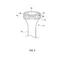
次に、図5を参照すると、この図はフランジ付き金属物品を製造するために本発明の方法を使用して修正された金属円筒14から作製されたフランジ付き金属物品10を表す。拘束用金属部材20で巻かれ、第1のろう付け化合物18と接触する円筒14の端部16は、フランジ付き部分がない金属円筒、第1のろう付け化合物18および拘束用金属部材20の組立体に熱処理をすると形成されるフランジ28を含む。言及したように、金属円筒は、拘束用金属部材20よりも大きく膨張し、加熱ステップ中に拘束用金属部材と密着嵌合するようになる。冷却すると、金属円筒と拘束用金属部材20との密着により、第1のろう付け化合物および拘束用金属部材と接触する金属円筒の部分の収縮が阻止され、フレア状端部28とも言及されるフランジ28の形成をもたらす。
Referring now to FIG. 5, this figure represents a
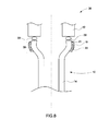
次に、図6を参照すると、この図はセラミック構成要素12に接合されたフランジ付き金属構成要素10を含む、本発明によって提供される物品32の概略横断面図を示す。図示の実施形態では、フランジ付き金属物品は、フランジ付き金属物品の上面24とセラミック物品12の間に第2のろう付け化合物30を付着することにより、セラミック物品12に接合される。フランジ付き金属物品10は、セラミック物品12に接合するために適合性のある形状および大きさを有することができる。1つの例示的実施形態では、フランジ付き金属物品10は同心のセラミック円筒との組合せで存在する。
Reference is now made to FIG. 6, which shows a schematic cross-sectional view of an
図7は、セラミック構成要素12に接合されたフランジ付き金属構成要素10を含む、本発明によって提供される物品34の概略横断面図を示す。図示の実施形態では、複数の層の拘束用金属部材20を含むフランジ付き部分を含むフランジ付き金属物品が、フランジ付き金属物品の上面24とセラミック構成要素12の間に配置された第2のろう付け化合物30を介してセラミック物品12に接合されている。
FIG. 7 shows a schematic cross-sectional view of an
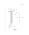
図8は、セラミック物品12に接合されたフランジ付き金属物品10を含む本発明によって提供される物品36を図示する。図7で図示された実施形態では、フランジ付き金属物品10が、フランジ28、第1のろう付け化合物18、および出発金属物品14の第1の部分の周りに巻かれた拘束用金属部材20を含み、出発金属物品14は、本発明の1つまたは複数の実施形態によって熱処理およびフランジ形成を受けたものである。
FIG. 8 illustrates an
一実施形態では、第1のろう付け化合物18および第2のろう付け化合物30は金基ろう付け材料を含むことができ、ろう付けに採用される1つまたは複数の接合技術によって金属物品14に接合することができる。ろう付け化合物は、金属物品14の面上に、被覆、貼合、溶接、めっき、蒸着、鋳造、機械的取付けまたは熱溶射技術などの様々な方法で直接配置されてよい。第2のろう付け化合物30は、フランジ付き金属構成要素10をセラミック構成要素12に接合するために使用され、フランジ付き金属構成要素、第2のろう付け化合物およびセラミック構成要素の組立体の熱処理によって生じる機械的変形に対処するのに役立つことがある。第1のろう付け化合物18および第2のろう付け化合物30は同一または異なる材料であってもよい。一実施形態では、第1のろう付け化合物18および第2のろう付け化合物30は、厳しい環境、例えば、ろう付け接合が同時に1つまたは複数の腐食性化学種(例えば、水と硫化水素ガスのガス状混合物)および高温(例えば、500℃)にさらされる環境で機能することができる。そのような環境は本明細書では時々、厳しい熱化学環境と言及される。
In one embodiment, the
様々な追加の層を本発明の1つまたは複数の実施形態によって採用することができる。例えば、追加の金属層が、出発金属物品の端部上、ろう付け化合物上、またはセラミック構成要素に接合されたフランジ付き金属構成要素を含むフランジ付き物品のセラミック構成要素上に配置されてよい。一実施形態では、本発明は、セラミック構成要素に接合されたフランジ付き金属構成要素を含む物品を提供し、その場合、金属性中間層が第2のろう付け化合物とセラミック構成要素の間に配置される。そのような金属性中間層は、フランジ付き金属構成要素をセラミック構成要素に接合することを促進することができる。そのような追加の金属層の適切な原料源には、金属箔、被覆および粉体が含まれる。一実施形態では、追加の金属層はモリブデンおよびマグネシウムを含み、当業者に知られている1つまたは複数の技術によって本発明が提供する物品に組み込まれることができる。一実施形態では、追加の層は、物品の1つまたは複数の面のぬれを促進するために本発明が提供する物品に組み込まれる。例えば、ニッケルを含むぬれ層は第2のろう付け化合物の接合の適合性を高めるために採用されることがある。適切なぬれ層は、例えば、電気めっき技術、および無電解ニッケルめっきなどの無電解めっき技術によって準備され得る。さらに、様々な保護被覆がろう付け化合物を覆って配置されてもよい。一実施形態では、フランジ付き金属構成要素とセラミック構成要素の間の接合を熱化学環境の劣化から保護するために、保護被覆が第2のろう付け化合物30(図8)の露出部分に付着される。
実施例
材料:直径5インチおよび壁厚0.25インチの脆弱な低膨張アルミナチューブがセラミック構成要素として使用された。セラミック構成要素に直接接合される高膨張金属物品は、大体同じ直径(5インチ)の厚さ0.035インチのINCONEL(登録商標)625チューブであった。直径0.015インチを有する長さ30フィートのモリブデン線(Rembar Co.)が拘束用金属部材として使用され、厚さ0.002インチ、幅0.5インチおよび長さ16インチを有する99.99%の金箔(Williams Advanced Materials)が第1のろう付け化合物として使用された。PALCUSIL10(Morgan Technical Ceramics−Wesgo Metals Division)が第2のろう付け化合物として使用された。
A variety of additional layers may be employed by one or more embodiments of the present invention. For example, an additional metal layer may be disposed on the end of the starting metal article, on the brazing compound, or on the ceramic component of the flanged article including the flanged metal component joined to the ceramic component. In one embodiment, the present invention provides an article comprising a flanged metal component joined to a ceramic component, wherein a metallic interlayer is disposed between the second brazing compound and the ceramic component. Is done. Such a metallic interlayer can facilitate joining the flanged metal component to the ceramic component. Suitable source sources for such additional metal layers include metal foils, coatings and powders. In one embodiment, the additional metal layer comprises molybdenum and magnesium and can be incorporated into the articles provided by the present invention by one or more techniques known to those skilled in the art. In one embodiment, additional layers are incorporated into the articles provided by the present invention to promote wetting of one or more surfaces of the article. For example, a wetting layer comprising nickel may be employed to enhance the bondability of the second brazing compound. A suitable wetting layer can be prepared, for example, by electroplating techniques and electroless plating techniques such as electroless nickel plating. In addition, various protective coatings may be placed over the brazing compound. In one embodiment, a protective coating is applied to the exposed portion of the second brazing compound 30 (FIG. 8) to protect the bond between the flanged metal component and the ceramic component from degradation of the thermochemical environment. The
Example Material: A fragile low expansion alumina tube with a diameter of 5 inches and a wall thickness of 0.25 inches was used as the ceramic component. The high expansion metal article bonded directly to the ceramic component was an INCONEL® 625 tube of approximately the same diameter (5 inches) and a thickness of 0.035 inches. A 30 foot long molybdenum wire (Rembar Co.) having a diameter of 0.015 inches was used as the restraining metal member and was 99.99 having a thickness of 0.002 inches, a width of 0.5 inches and a length of 16 inches. % Gold foil (Williams Advanced Materials) was used as the first brazing compound. PALCUSIL10 (Morgan Technical Ceramics-Wesgo Metals Division) was used as the second brazing compound.
フランジ付き金属物品の準備
厚さ約0.035インチを有するINCONEL(登録商標)625シートが円筒形状に巻かれ、継ぎ目が溶接されて直径約4.85インチを有するチューブを製造した。金属プラグがチューブ端部に挿入されて、チューブの丸みを維持し、回転軸の周りの担体をもたらした。金箔の第1のろう付け化合物はチューブ端部の外側面に仮付け溶接された。直径0.015インチを有する長さ30フィートのモリブデン線が、金箔の第1のろう付け化合物の頂部に手で巻かれた。モリブデン線の複数回のターンがチューブの周りに作製され、各ターン(巻回)は隣接するターンに近接または接触し、第1のろう付け化合物に接触した。次いで、モリブデン線の端部は、一体に捩じられてターンを定位置に保持し、結果として生じた組立体が真空炉内に配置され、1107℃の温度で1分間加熱されて、フランジ付き金属物品を形成した。そのような加熱手順は金基ろう付け化合物を使用するときに典型的なものである。フランジ付き金属物品はフランジ領域内とその周辺で均一なろう付け化合物流を示した。
Preparation of flanged metal articles INCONEL® 625 sheet having a thickness of about 0.035 inches was rolled into a cylindrical shape and the seam welded to produce a tube having a diameter of about 4.85 inches. A metal plug was inserted at the end of the tube to maintain the roundness of the tube and provide a support around the axis of rotation. The first brazing compound of the gold foil was tack welded to the outer surface of the tube end. A 30 foot long molybdenum wire having a diameter of 0.015 inches was manually wound on top of the first brazing compound of gold foil. Multiple turns of molybdenum wire were made around the tube, and each turn (turn) was in close proximity to or in contact with an adjacent turn and contacted the first brazing compound. The ends of the molybdenum wire are then twisted together to hold the turn in place and the resulting assembly is placed in a vacuum furnace and heated at a temperature of 1107 ° C. for 1 minute to be flanged A metal article was formed. Such a heating procedure is typical when using gold-based brazing compounds. The flanged metal article showed a uniform brazing compound flow in and around the flange area.
熱処理中に、チューブはモリブデン線よりも大きく膨張し、モリブデン線と密着嵌合の状態になった。冷却すると、モリブデン線はチューブの端部を制約し、チューブの端部が元の形状および大きさに収縮して戻ることを防止し、その結果、チューブの端部は、例えば図4に示す金属フランジに変形した。結果として生じたチューブの変形は、座標測定機(CMM)を使用して測定された。座標測定機で得られた結果を分析すると、この実施例で使用された厚さ0,035インチの金属物品と併せて、拘束用金属部材用には厚さ0.04インチのモリブデン線が最適な厚さであると示唆した。さらに、その結果によると、拘束用金属部材として厚さ0.04インチのモリブデン線の使用が、結果として生じたフランジの熱膨張特性とアルミナセラミック構成要素の熱膨張特性の間に良好な適合を可能にすることを示唆した。 During the heat treatment, the tube expanded more than the molybdenum wire and was in close contact with the molybdenum wire. When cooled, the molybdenum wire constrains the end of the tube and prevents the end of the tube from shrinking and returning to its original shape and size, so that the end of the tube is, for example, the metal shown in FIG. Deformed into a flange. The resulting tube deformation was measured using a coordinate measuring machine (CMM). Analysis of the results obtained with the coordinate measuring machine shows that 0.04 inch thick molybdenum wire is optimal for constraining metal parts in conjunction with the 0.035 inch thick metal article used in this example. The thickness was suggested. Furthermore, the results show that the use of 0.04 inch thick molybdenum wire as the constraining metal member provides a good fit between the thermal expansion characteristics of the resulting flange and the alumina ceramic component. Suggested to make it possible.
金の第1のろう付け化合物で処理された厚さ0.035インチおよび直径約5インチを有する3つのINCONEL(登録商標)625チューブが、厚さ0.04インチのモリブデン線で巻かれ、実施例1のように熱処理をされて、3つのフランジ付き金属物品を提供した。第2のろう付け化合物(PALCUSIL−10)が、3つのフランジ付き金属物品のそれぞれのフランジ付き部分の上面(例えば、図5の要素24参照)に付着された。次いで、フランジ付き金属物品のフランジ付き部分と大体同じ直径および厚さをそれぞれ有する3つのアルミナセラミックチューブを、3つのフランジ付き金属物品のそれぞれと接触させ、第2のろう付け化合物がフランジ付き金属物品およびセラミックチューブの両方に接触するようになった。次いで、フランジ付き金属物品、第2のろう付け化合物およびセラミックチューブの組立体は、以下の加熱手順、725℃で3時間、830℃で1分間、881℃で1分間、真空で加熱されて、セラミックチューブをフランジ付き金属物品に接合し、セラミック構成要素に接合されたフランジ付き金属構成要素を含む製造物品が得られた。モリブデン線とインコネル625チューブの間の金含有ろう付け接合はこの第2の加熱ステップにより阻害されることはなかったが、その理由は、第1のろう付け化合物が第2の加熱手順中に流れないように、第2のろう付け化合物(PALCUSIL−10)が、セラミックチューブをフランジ付き金属物品に十分低い温度で効果的に接合したからである。
Three INCONEL® 625 tubes treated with a gold first brazing compound and having a thickness of about 35 inches and a diameter of about 5 inches were wrapped with 0.04 inch thick molybdenum wire and run Heat treated as in Example 1 to provide three flanged metal articles. A second brazing compound (PALCUSIL-10) was deposited on the top surface of each flanged portion of the three flanged metal articles (see, for example,
引張試験が3つの製造物品のそれぞれに実施された。したがって、引張負荷がインコネル625チューブの端部に加えられた。最大3635フィートポンドの引張負荷(物品1)、最大14,898フィートポンドの引張負荷(物品2)および最大14,414フィートポンドの引張負荷(物品3)が表示された。セラミックチューブ構成要素の接合面とフランジ付きインコネル625チューブ構成要素の接合面との間の第2のろう付け化合物による被覆が不十分であるために、第1の部片の損傷がろう付け化合物内に直接観察された。物品2および物品3の場合、PALCUSIL−10ろう付け接合に隣接するセラミックに割れ目が生じたことによる損傷が観察された。あるセラミック材料は損傷後、インコネル625フランジ上に依然として無傷であったが、これにより、ろう付け接合の強度が接合近傍のセラミックチューブの強度を超えることを示した。
比較例1:拘束用金属部材のないろう付け
対照実験として、実施例1および2で採用されたようなインコネル625チューブが拘束用金属部材の存在しないセラミックチューブにろう付けされたが、その結果セラミックチューブはろう付け熱処理中に損傷した。この結果はろう付けステップ中にセラミック内に誘発された応力がセラミックの強度を超えるであろうと予測した分析と一致する。比較例1の結果は実施例2で得られた結果と全く対照的であり、実施例2では、室温での物品のセラミック部分内の残留応力は十分に低かったので、セラミックが損傷する前にかなりの追加の引張負荷を重ねることが可能であった。
Tensile tests were performed on each of the three manufactured articles. Therefore, a tensile load was applied to the end of the Inconel 625 tube. Up to 3635 ft-lb tensile load (article 1), up to 14,898 ft-lb tensile load (article 2) and up to 14,414 ft-lb tensile load (article 3) were displayed. Insufficient coverage with the second brazing compound between the joining surface of the ceramic tube component and the flanged Inconel 625 tube component causes damage to the first piece within the brazing compound. Directly observed. In the case of
Comparative Example 1: Brazing without a constraining metal member As a control experiment, an Inconel 625 tube as employed in Examples 1 and 2 was brazed to a ceramic tube without a constraining metal member, resulting in ceramic The tube was damaged during the brazing heat treatment. This result is consistent with the analysis that predicted that the stress induced in the ceramic during the brazing step would exceed the strength of the ceramic. The results of Comparative Example 1 are in stark contrast to the results obtained in Example 2, in which the residual stress in the ceramic portion of the article at room temperature was sufficiently low so that before the ceramic was damaged It was possible to apply considerable additional tensile loads.
本発明は実施例、比較例および例示的実施形態を参照して説明されたが、当業者なら、様々な変形形態が作製可能であり、等価の要素が、発明者らによって着想された本発明の範囲から離れずに本発明を説明するために使用される請求項の要素に代替され得ることを理解するであろう。さらに、修正形態が、発明者らによって着想された本発明の範囲から離れずに、特定の出願に本発明を適合させるために本発明の教示に対して作製され得る。したがって、本発明が、本発明を実施するために開示された実施形態に制限されるものではなく、本発明は意図された特許請求の範囲内に収まるすべての実施形態を含むことを意図するものである。本書は、最良の形態を含めて、本発明を開示するために、また任意の装置またはシステムを作製および使用すること、ならびに任意の組み込まれた方法を実行することを含めて、当業者が本発明を実施することができるように例を使用している。本発明の特許性のある範囲は、特許請求の範囲によって定義され、当業者に生じる他の実施例を含むことができる。そのような他の実施例は、それらが特許請求の範囲の文字通りの言語から異ならない構造上の要素を有する場合、またはそれらが特許請求の範囲の文字通りの言語からごくわずかな相違しかない等価の構造上の要素を含む場合、特許請求の範囲内にあるものとする。 Although the present invention has been described with reference to examples, comparative examples and exemplary embodiments, various modifications can be made by those skilled in the art, and equivalent elements are conceived by the inventors. It will be understood that alternatives may be made to the elements of the claims used to describe the invention without departing from the scope of the invention. Moreover, modifications can be made to the teachings of the invention to adapt the invention to a particular application without departing from the scope of the invention as conceived by the inventors. Accordingly, the invention is not limited to the disclosed embodiments for carrying out the invention, but the invention is intended to include all embodiments that fall within the scope of the intended claims. It is. This document is intended to be useful to those of ordinary skill in the art, including the best mode, to disclose the invention, and to make and use any device or system and perform any integrated methods. An example is used so that the invention can be implemented. The patentable scope of the invention is defined by the claims, and may include other examples that occur to those skilled in the art. Such other embodiments are equivalent if they have structural elements that do not differ from the literal language of the claims, or if they have only minor differences from the literal language of the claims. The inclusion of structural elements is intended to be within the scope of the claims.
8 加熱前の金属フランジ
10 加熱後の金属フランジ
12 セラミック物品
14 金属物品
16 端部/金属物品の第1の部分
18 第1のろう付け化合物
20 拘束用金属部材
22 インコネルパイプの内側面
24 インコネルパイプの上面
26 パイプ上面24と巻かれた部分の頂部の間の間隙
28 加熱後の円筒のフレア状部分
30 第2のろう付け化合物
32 セラミック構成要素12に接合されたフランジ付き金属構成要素10(拘束用金属部材20の単一の層を含む)を含む物品の部分
34 セラミック構成要素12に接合されたフランジ付き金属構成要素10(拘束用金属部材20の複数の層を含む)を含む物品の部分
36 フランジ付き金属物品/セラミック物品12に接合されたフランジ付き金属物品10を含む物品
8 Metal flange before heating 10 Metal flange after heating 12
Claims (10)
(a)第1のろう付け化合物(18)を金属物品(14)の第1の部分(16)に付着するステップと、
(b)前記金属物品の前記第1の部分(16)をある長さの拘束用金属部材(20)で巻くステップと、
(c)前記金属物品(14)、前記拘束用金属部材(20)および前記第1のろう付け化合物(18)の組立体を前記ろう付け化合物の固相線温度を超える温度まで加熱して、フランジ付き金属物品(10)を製造するステップと
を含み、
前記金属物品(14)が熱膨張係数CTE1を有し、前記拘束用金属部材(20)が熱膨張係数CTE2を有し、CTE1がCTE2よりも大きい方法。 A method for making a flanged metal article (10) comprising:
(A) attaching a first brazing compound (18) to a first portion (16) of a metal article (14);
(B) winding the first portion (16) of the metal article with a length of restraining metal member (20);
(C) heating the assembly of the metal article (14), the constraining metal member (20) and the first brazing compound (18) to a temperature above the solidus temperature of the brazing compound; Producing a flanged metal article (10),
The method wherein the metal article (14) has a coefficient of thermal expansion CTE1, the constraining metal member (20) has a coefficient of thermal expansion CTE2, and CTE1 is greater than CTE2.
(b)前記フランジ付き金属構成要素(10)および前記モリブデン線(20)の面に接触する第1のろう付け化合物(18)と
を含むフランジ付き物品(36)であって、
前記フランジ付き金属構成要素(10)が熱膨張係数CTE1を有し、前記モリブデン線が熱膨張係数CTE2を有し、CTE1がCTE2よりも少なくとも100%大きい、フランジ付き物品(36)。 (A) A flanged metal component (10) joined to a ceramic component (20), wound with molybdenum wire (20) and comprising one or more of nickel, iron, cobalt, and chromium A flanged metal component (10);
(B) a flanged article (36) comprising the flanged metal component (10) and a first brazing compound (18) in contact with a surface of the molybdenum wire (20),
The flanged article (36), wherein the flanged metal component (10) has a coefficient of thermal expansion CTE1, the molybdenum wire has a coefficient of thermal expansion CTE2, and CTE1 is at least 100% greater than CTE2.
(a)第1のろう付け化合物(18)を金属物品の第1の部分(16)に付着するステップと、
(b)前記金属物品の前記第1の部分をある長さの拘束用金属部材(20)で巻くステップと、
(c)前記金属物品(10)、前記拘束用金属部材(20)および前記第1のろう付け化合物(18)の組立体を前記第1のろう付け化合物(18)の固相線温度を超える温度まで加熱して、フランジ付き金属物品(36)を製造するステップであり、前記金属物品(14)が熱膨張係数CTE1を有し、前記拘束用金属部材(20)が熱膨張係数CTE2を有し、CTE1がCTE2よりも大きいステップと、
(d)前記フランジ付き金属物品(36)のフランジ付き部分(10)を第2のろう付け化合物(30)およびセラミック物品(12)に接触させるステップであり、前記第2のろう付け化合物が前記金属物品の前記フランジ付き部分と前記セラミック物品の間に配置されるようになっているステップと、
(e)前記フランジ付き金属物品、前記第2のろう付け化合物および前記セラミック物品の組立体を前記第2のろう付け化合物の固相線温度を超える温度まで加熱して、前記セラミック構成要素に接合された前記フランジ付き金属構成要素を含む物品を製造するステップと
を含む方法。 A method of making an article (36) comprising a flanged metal component (10) joined to a ceramic component (12) comprising:
(A) attaching a first brazing compound (18) to a first portion (16) of a metal article;
(B) winding the first portion of the metal article with a length of constraining metal member (20);
(C) The assembly of the metal article (10), the constraining metal member (20) and the first brazing compound (18) exceeds the solidus temperature of the first brazing compound (18) Heating to temperature to produce a flanged metal article (36) wherein the metal article (14) has a coefficient of thermal expansion CTE1 and the constraining metal member (20) has a coefficient of thermal expansion CTE2. A step in which CTE1 is greater than CTE2,
(D) contacting the flanged portion (10) of the flanged metal article (36) with a second brazing compound (30) and a ceramic article (12), wherein the second brazing compound is A step adapted to be disposed between the flanged portion of the metal article and the ceramic article;
(E) heating the flanged metal article, the second brazing compound and the ceramic article assembly to a temperature above the solidus temperature of the second brazing compound to join the ceramic component; Manufacturing an article comprising said flanged metal component.
Applications Claiming Priority (2)
| Application Number | Priority Date | Filing Date | Title |
|---|---|---|---|
| US13/032,315 US20120214016A1 (en) | 2011-02-22 | 2011-02-22 | Constrained metal flanges and methods for making the same |
| US13/032,315 | 2011-02-22 |
Publications (1)
| Publication Number | Publication Date |
|---|---|
| JP2012183585A true JP2012183585A (en) | 2012-09-27 |
Family
ID=45656017
Family Applications (1)
| Application Number | Title | Priority Date | Filing Date |
|---|---|---|---|
| JP2012033477A Pending JP2012183585A (en) | 2011-02-22 | 2012-02-20 | Fixed metal flange and method of producing the same |
Country Status (9)
| Country | Link |
|---|---|
| US (1) | US20120214016A1 (en) |
| EP (1) | EP2492029B1 (en) |
| JP (1) | JP2012183585A (en) |
| KR (1) | KR20120097464A (en) |
| CN (1) | CN102672357B (en) |
| AU (1) | AU2012200974B2 (en) |
| CA (1) | CA2768120A1 (en) |
| IN (1) | IN2012DE00427A (en) |
| RU (1) | RU2591867C2 (en) |
Cited By (2)
| Publication number | Priority date | Publication date | Assignee | Title |
|---|---|---|---|---|
| WO2016051902A1 (en) * | 2014-09-30 | 2016-04-07 | 株式会社リアリティ・デンタル・ラボラトリー | Implant upper part structure |
| JP2017514137A (en) * | 2014-04-24 | 2017-06-01 | トライアンフTriumf | Target system for irradiating molybdenum with particle beam |
Families Citing this family (6)
| Publication number | Priority date | Publication date | Assignee | Title |
|---|---|---|---|---|
| US8960525B2 (en) * | 2013-01-31 | 2015-02-24 | General Electric Company | Brazing process and plate assembly |
| US10782016B2 (en) * | 2015-03-12 | 2020-09-22 | General Electric Technology Gmbh | System and method for reducing emissions in a chemical looping combustion system |
| CN107175421B (en) * | 2017-07-06 | 2019-06-11 | 武汉理工大学 | A kind of compressive pre-stress bimetal centrifugal is cast the welding procedures of compound pipe end flanges |
| CN111001890A (en) * | 2019-12-16 | 2020-04-14 | 中国电子科技集团公司第四十三研究所 | Method for reducing welding deformation of heterogeneous material |
| EP3845971B1 (en) * | 2019-12-31 | 2024-04-17 | Nivarox-FAR S.A. | Method for manufacturing an hairspring for clock movement |
| KR102506712B1 (en) * | 2021-02-03 | 2023-03-07 | 주식회사 오성테크 | Bonding method for Tool steel and, the mold manufactured by the same |
Citations (7)
| Publication number | Priority date | Publication date | Assignee | Title |
|---|---|---|---|---|
| US3191288A (en) * | 1959-09-10 | 1965-06-29 | Quartz & Silice S A | Method of forming assemblies incorporating soldered joints |
| JPS54101816A (en) * | 1978-01-27 | 1979-08-10 | Nippon Electric Co | Brazing method |
| JPS62252201A (en) * | 1986-04-25 | 1987-11-04 | Toshiba Corp | Airtight joined body structure for ceramics plate and metallic cylinder |
| JPH01115879A (en) * | 1987-10-27 | 1989-05-09 | Yasuhide Minonishi | Conjugate form made from ceramics and metal |
| US5153077A (en) * | 1988-07-22 | 1992-10-06 | Mitsubishi Denki Kabushiki Kaisha | Ceramic-metal composite substrate |
| JP2000169252A (en) * | 1998-11-30 | 2000-06-20 | Kyocera Corp | Bonded material of ceramic member and metal member and wafer supporting member using the same |
| WO2006090730A1 (en) * | 2005-02-23 | 2006-08-31 | Kyocera Corporation | Joined article and member for holding wafer and structure for mounting the same, and method for treating wafer |
Family Cites Families (12)
| Publication number | Priority date | Publication date | Assignee | Title |
|---|---|---|---|---|
| GB769108A (en) * | 1953-09-18 | 1957-02-27 | Omnicoil Entpr Inc | A method of manufacturing articles of irregular cross-section and articles made by said method |
| GB1107764A (en) * | 1965-01-07 | 1968-03-27 | Gen Electric Co Ltd | Improvements in or relating to the closure of tubes of refractory oxide material |
| SU730662A1 (en) * | 1978-08-28 | 1980-04-30 | Предприятие П/Я В-2058 | Ceramics-to-metal telescopic joint structure |
| DE3151487C2 (en) * | 1981-12-24 | 1983-12-22 | Messerschmitt-Bölkow-Blohm GmbH, 8000 München | Fiber-reinforced metal tube |
| JPS6314829A (en) * | 1986-07-08 | 1988-01-22 | Tokyo Shiyouketsu Kinzoku Kk | Production of high heat conductivity member having anisotropic coefficient of thermal expansion |
| US4890783A (en) * | 1988-11-29 | 1990-01-02 | Li Chou H | Ceramic-metal joining |
| JP2903743B2 (en) * | 1991-02-28 | 1999-06-14 | いすゞ自動車株式会社 | Structure of combustion chamber and method of manufacturing the same |
| EP0743131A1 (en) * | 1995-05-17 | 1996-11-20 | Kabushiki Kaisha Toshiba | Ceramic metal bonding |
| CN1061283C (en) * | 1997-09-10 | 2001-01-31 | 西安交通大学 | Method for increasing strength of ceramic and metal soldered joint |
| JP2000343210A (en) * | 1999-03-31 | 2000-12-12 | Komatsu Ltd | Double structure tube and its production |
| JP2001130976A (en) * | 1999-11-01 | 2001-05-15 | Mitsubishi Electric Corp | Method for bonding ceramic to metal and bonded body between ceramic and metal bonded by the method |
| CN100537483C (en) * | 2004-06-08 | 2009-09-09 | 日本碍子株式会社 | Brittle material-metal structure |
-
2011
- 2011-02-22 US US13/032,315 patent/US20120214016A1/en not_active Abandoned
-
2012
- 2012-02-15 IN IN427DE2012 patent/IN2012DE00427A/en unknown
- 2012-02-16 CA CA2768120A patent/CA2768120A1/en not_active Abandoned
- 2012-02-17 EP EP12155906.6A patent/EP2492029B1/en not_active Not-in-force
- 2012-02-20 AU AU2012200974A patent/AU2012200974B2/en not_active Ceased
- 2012-02-20 JP JP2012033477A patent/JP2012183585A/en active Pending
- 2012-02-21 KR KR1020120017605A patent/KR20120097464A/en not_active Application Discontinuation
- 2012-02-21 RU RU2012106763/03A patent/RU2591867C2/en not_active IP Right Cessation
- 2012-02-22 CN CN201210050337.4A patent/CN102672357B/en not_active Expired - Fee Related
Patent Citations (7)
| Publication number | Priority date | Publication date | Assignee | Title |
|---|---|---|---|---|
| US3191288A (en) * | 1959-09-10 | 1965-06-29 | Quartz & Silice S A | Method of forming assemblies incorporating soldered joints |
| JPS54101816A (en) * | 1978-01-27 | 1979-08-10 | Nippon Electric Co | Brazing method |
| JPS62252201A (en) * | 1986-04-25 | 1987-11-04 | Toshiba Corp | Airtight joined body structure for ceramics plate and metallic cylinder |
| JPH01115879A (en) * | 1987-10-27 | 1989-05-09 | Yasuhide Minonishi | Conjugate form made from ceramics and metal |
| US5153077A (en) * | 1988-07-22 | 1992-10-06 | Mitsubishi Denki Kabushiki Kaisha | Ceramic-metal composite substrate |
| JP2000169252A (en) * | 1998-11-30 | 2000-06-20 | Kyocera Corp | Bonded material of ceramic member and metal member and wafer supporting member using the same |
| WO2006090730A1 (en) * | 2005-02-23 | 2006-08-31 | Kyocera Corporation | Joined article and member for holding wafer and structure for mounting the same, and method for treating wafer |
Cited By (2)
| Publication number | Priority date | Publication date | Assignee | Title |
|---|---|---|---|---|
| JP2017514137A (en) * | 2014-04-24 | 2017-06-01 | トライアンフTriumf | Target system for irradiating molybdenum with particle beam |
| WO2016051902A1 (en) * | 2014-09-30 | 2016-04-07 | 株式会社リアリティ・デンタル・ラボラトリー | Implant upper part structure |
Also Published As
| Publication number | Publication date |
|---|---|
| RU2591867C2 (en) | 2016-07-20 |
| EP2492029A1 (en) | 2012-08-29 |
| EP2492029B1 (en) | 2013-12-18 |
| AU2012200974A1 (en) | 2012-09-06 |
| RU2012106763A (en) | 2013-08-27 |
| AU2012200974B2 (en) | 2016-09-15 |
| CN102672357A (en) | 2012-09-19 |
| US20120214016A1 (en) | 2012-08-23 |
| CN102672357B (en) | 2016-04-20 |
| IN2012DE00427A (en) | 2015-06-05 |
| CA2768120A1 (en) | 2012-08-22 |
| KR20120097464A (en) | 2012-09-04 |
Similar Documents
| Publication | Publication Date | Title |
|---|---|---|
| JP2012183585A (en) | Fixed metal flange and method of producing the same | |
| EP0215554B1 (en) | Method of producing brazing metals | |
| JP5102814B2 (en) | High strength dissimilar metal joining method of steel alloy and titanium or titanium alloy using intermediate layer having joining strength exceeding base material strength, and steel alloy and titanium or titanium alloy joined by the method High strength bonding alloy containing | |
| KR100984089B1 (en) | Zirconium-coated steel plates and chemical device elements produced with such plates | |
| KR20100091178A (en) | Joining and material application method for a workpiece having a workpiece region comprising a titanium aluminide alloy | |
| JPH04228480A (en) | Composite being stable at high temperature and preparation thereof | |
| KR100849385B1 (en) | Article including a composite of unstabilized zirconium oxide particles in a metallic matrix, and its preparation | |
| CN113909610A (en) | High-performance brazing method for third-generation single crystal high-temperature alloy | |
| TW200927346A (en) | A diffusion bonding method for blocks of based bulk metallic glass | |
| EP1500455A1 (en) | Method for obtaining high-resistance brazed joints of multiple-layer composite materials of ceramic/ceramic and metal/ceramic type, and multiple-layer composite materials obtained through the said method | |
| JP3240211B2 (en) | Copper-aluminum dissimilar metal joint material | |
| KR101039361B1 (en) | Low temperature joining method between Ti/Ti-based alloys having a bonding strength higher than those of base metals | |
| US7578424B2 (en) | Method of joining a microwave transparent component to a host component | |
| JP6333268B2 (en) | Layer composite | |
| Yeh et al. | Transient liquid phase metallic bonding of an Inconel 718SPF superalloy | |
| JP4331370B2 (en) | Method for manufacturing HIP joined body of beryllium and copper alloy and HIP joined body | |
| US10767501B2 (en) | Article, component, and method of making a component | |
| JP2003253302A (en) | Oxidation resistant coated niobium-base alloy and its manufacturing method | |
| JP4446073B2 (en) | Joining method of titanium aluminum intermetallic compound and copper alloy | |
| JP2001048670A (en) | Ceramics-metal joined body | |
| CN115194275A (en) | Method for brazing dissimilar metals of titanium alloy and nickel-based superalloy | |
| JPH05228624A (en) | Soldering tool of diamond polycrystalline body | |
| JPS62297275A (en) | Joined body of non-oxide ceramic and metal | |
| JPH11254128A (en) | Joining method of metal part | |
| Chekunov | Examination of the feasibility of fluxless brazing titanium pipelines |
Legal Events
| Date | Code | Title | Description |
|---|---|---|---|
| A621 | Written request for application examination |
Free format text: JAPANESE INTERMEDIATE CODE: A621 Effective date: 20150209 |
|
| A977 | Report on retrieval |
Free format text: JAPANESE INTERMEDIATE CODE: A971007 Effective date: 20160129 |
|
| A131 | Notification of reasons for refusal |
Free format text: JAPANESE INTERMEDIATE CODE: A131 Effective date: 20160202 |
|
| A521 | Request for written amendment filed |
Free format text: JAPANESE INTERMEDIATE CODE: A523 Effective date: 20160425 |
|
| A131 | Notification of reasons for refusal |
Free format text: JAPANESE INTERMEDIATE CODE: A131 Effective date: 20160823 |
|
| A131 | Notification of reasons for refusal |
Free format text: JAPANESE INTERMEDIATE CODE: A131 Effective date: 20170307 |
|
| A02 | Decision of refusal |
Free format text: JAPANESE INTERMEDIATE CODE: A02 Effective date: 20171107 |