JP2012183533A - Method and apparatus for thermal swing adsorption and thermally-enhanced pressure swing adsorption - Google Patents
Method and apparatus for thermal swing adsorption and thermally-enhanced pressure swing adsorption Download PDFInfo
- Publication number
- JP2012183533A JP2012183533A JP2012087501A JP2012087501A JP2012183533A JP 2012183533 A JP2012183533 A JP 2012183533A JP 2012087501 A JP2012087501 A JP 2012087501A JP 2012087501 A JP2012087501 A JP 2012087501A JP 2012183533 A JP2012183533 A JP 2012183533A
- Authority
- JP
- Japan
- Prior art keywords
- adsorption
- heat
- gas
- cell
- heat exchanger
- Prior art date
- Legal status (The legal status is an assumption and is not a legal conclusion. Google has not performed a legal analysis and makes no representation as to the accuracy of the status listed.)
- Pending
Links
Images


Classifications
-
- H—ELECTRICITY
- H01—ELECTRIC ELEMENTS
- H01M—PROCESSES OR MEANS, e.g. BATTERIES, FOR THE DIRECT CONVERSION OF CHEMICAL ENERGY INTO ELECTRICAL ENERGY
- H01M8/00—Fuel cells; Manufacture thereof
- H01M8/06—Combination of fuel cells with means for production of reactants or for treatment of residues
- H01M8/0662—Treatment of gaseous reactants or gaseous residues, e.g. cleaning
-
- B—PERFORMING OPERATIONS; TRANSPORTING
- B01—PHYSICAL OR CHEMICAL PROCESSES OR APPARATUS IN GENERAL
- B01D—SEPARATION
- B01D53/00—Separation of gases or vapours; Recovering vapours of volatile solvents from gases; Chemical or biological purification of waste gases, e.g. engine exhaust gases, smoke, fumes, flue gases, aerosols
- B01D53/02—Separation of gases or vapours; Recovering vapours of volatile solvents from gases; Chemical or biological purification of waste gases, e.g. engine exhaust gases, smoke, fumes, flue gases, aerosols by adsorption, e.g. preparative gas chromatography
- B01D53/06—Separation of gases or vapours; Recovering vapours of volatile solvents from gases; Chemical or biological purification of waste gases, e.g. engine exhaust gases, smoke, fumes, flue gases, aerosols by adsorption, e.g. preparative gas chromatography with moving adsorbents, e.g. rotating beds
-
- C—CHEMISTRY; METALLURGY
- C01—INORGANIC CHEMISTRY
- C01B—NON-METALLIC ELEMENTS; COMPOUNDS THEREOF; METALLOIDS OR COMPOUNDS THEREOF NOT COVERED BY SUBCLASS C01C
- C01B3/00—Hydrogen; Gaseous mixtures containing hydrogen; Separation of hydrogen from mixtures containing it; Purification of hydrogen
- C01B3/50—Separation of hydrogen or hydrogen containing gases from gaseous mixtures, e.g. purification
- C01B3/56—Separation of hydrogen or hydrogen containing gases from gaseous mixtures, e.g. purification by contacting with solids; Regeneration of used solids
-
- H—ELECTRICITY
- H01—ELECTRIC ELEMENTS
- H01M—PROCESSES OR MEANS, e.g. BATTERIES, FOR THE DIRECT CONVERSION OF CHEMICAL ENERGY INTO ELECTRICAL ENERGY
- H01M8/00—Fuel cells; Manufacture thereof
- H01M8/02—Details
- H01M8/0202—Collectors; Separators, e.g. bipolar separators; Interconnectors
- H01M8/0258—Collectors; Separators, e.g. bipolar separators; Interconnectors characterised by the configuration of channels, e.g. by the flow field of the reactant or coolant
- H01M8/0263—Collectors; Separators, e.g. bipolar separators; Interconnectors characterised by the configuration of channels, e.g. by the flow field of the reactant or coolant having meandering or serpentine paths
-
- H—ELECTRICITY
- H01—ELECTRIC ELEMENTS
- H01M—PROCESSES OR MEANS, e.g. BATTERIES, FOR THE DIRECT CONVERSION OF CHEMICAL ENERGY INTO ELECTRICAL ENERGY
- H01M8/00—Fuel cells; Manufacture thereof
- H01M8/02—Details
- H01M8/0202—Collectors; Separators, e.g. bipolar separators; Interconnectors
- H01M8/0267—Collectors; Separators, e.g. bipolar separators; Interconnectors having heating or cooling means, e.g. heaters or coolant flow channels
-
- H—ELECTRICITY
- H01—ELECTRIC ELEMENTS
- H01M—PROCESSES OR MEANS, e.g. BATTERIES, FOR THE DIRECT CONVERSION OF CHEMICAL ENERGY INTO ELECTRICAL ENERGY
- H01M8/00—Fuel cells; Manufacture thereof
- H01M8/04—Auxiliary arrangements, e.g. for control of pressure or for circulation of fluids
- H01M8/04007—Auxiliary arrangements, e.g. for control of pressure or for circulation of fluids related to heat exchange
- H01M8/04014—Heat exchange using gaseous fluids; Heat exchange by combustion of reactants
-
- H—ELECTRICITY
- H01—ELECTRIC ELEMENTS
- H01M—PROCESSES OR MEANS, e.g. BATTERIES, FOR THE DIRECT CONVERSION OF CHEMICAL ENERGY INTO ELECTRICAL ENERGY
- H01M8/00—Fuel cells; Manufacture thereof
- H01M8/04—Auxiliary arrangements, e.g. for control of pressure or for circulation of fluids
- H01M8/04223—Auxiliary arrangements, e.g. for control of pressure or for circulation of fluids during start-up or shut-down; Depolarisation or activation, e.g. purging; Means for short-circuiting defective fuel cells
- H01M8/04225—Auxiliary arrangements, e.g. for control of pressure or for circulation of fluids during start-up or shut-down; Depolarisation or activation, e.g. purging; Means for short-circuiting defective fuel cells during start-up
-
- H—ELECTRICITY
- H01—ELECTRIC ELEMENTS
- H01M—PROCESSES OR MEANS, e.g. BATTERIES, FOR THE DIRECT CONVERSION OF CHEMICAL ENERGY INTO ELECTRICAL ENERGY
- H01M8/00—Fuel cells; Manufacture thereof
- H01M8/04—Auxiliary arrangements, e.g. for control of pressure or for circulation of fluids
- H01M8/04298—Processes for controlling fuel cells or fuel cell systems
- H01M8/043—Processes for controlling fuel cells or fuel cell systems applied during specific periods
- H01M8/04302—Processes for controlling fuel cells or fuel cell systems applied during specific periods applied during start-up
-
- H—ELECTRICITY
- H01—ELECTRIC ELEMENTS
- H01M—PROCESSES OR MEANS, e.g. BATTERIES, FOR THE DIRECT CONVERSION OF CHEMICAL ENERGY INTO ELECTRICAL ENERGY
- H01M8/00—Fuel cells; Manufacture thereof
- H01M8/24—Grouping of fuel cells, e.g. stacking of fuel cells
- H01M8/2465—Details of groupings of fuel cells
- H01M8/2483—Details of groupings of fuel cells characterised by internal manifolds
-
- B—PERFORMING OPERATIONS; TRANSPORTING
- B01—PHYSICAL OR CHEMICAL PROCESSES OR APPARATUS IN GENERAL
- B01D—SEPARATION
- B01D2253/00—Adsorbents used in seperation treatment of gases and vapours
- B01D2253/10—Inorganic adsorbents
- B01D2253/106—Silica or silicates
- B01D2253/108—Zeolites
-
- B—PERFORMING OPERATIONS; TRANSPORTING
- B01—PHYSICAL OR CHEMICAL PROCESSES OR APPARATUS IN GENERAL
- B01D—SEPARATION
- B01D2257/00—Components to be removed
- B01D2257/50—Carbon oxides
- B01D2257/504—Carbon dioxide
-
- B—PERFORMING OPERATIONS; TRANSPORTING
- B01—PHYSICAL OR CHEMICAL PROCESSES OR APPARATUS IN GENERAL
- B01D—SEPARATION
- B01D2257/00—Components to be removed
- B01D2257/80—Water
-
- B—PERFORMING OPERATIONS; TRANSPORTING
- B01—PHYSICAL OR CHEMICAL PROCESSES OR APPARATUS IN GENERAL
- B01D—SEPARATION
- B01D2259/00—Type of treatment
- B01D2259/40—Further details for adsorption processes and devices
- B01D2259/40083—Regeneration of adsorbents in processes other than pressure or temperature swing adsorption
- B01D2259/40088—Regeneration of adsorbents in processes other than pressure or temperature swing adsorption by heating
-
- B—PERFORMING OPERATIONS; TRANSPORTING
- B01—PHYSICAL OR CHEMICAL PROCESSES OR APPARATUS IN GENERAL
- B01D—SEPARATION
- B01D2259/00—Type of treatment
- B01D2259/45—Gas separation or purification devices adapted for specific applications
- B01D2259/4566—Gas separation or purification devices adapted for specific applications for use in transportation means
- B01D2259/4575—Gas separation or purification devices adapted for specific applications for use in transportation means in aeroplanes or space ships
-
- B—PERFORMING OPERATIONS; TRANSPORTING
- B01—PHYSICAL OR CHEMICAL PROCESSES OR APPARATUS IN GENERAL
- B01D—SEPARATION
- B01D53/00—Separation of gases or vapours; Recovering vapours of volatile solvents from gases; Chemical or biological purification of waste gases, e.g. engine exhaust gases, smoke, fumes, flue gases, aerosols
- B01D53/02—Separation of gases or vapours; Recovering vapours of volatile solvents from gases; Chemical or biological purification of waste gases, e.g. engine exhaust gases, smoke, fumes, flue gases, aerosols by adsorption, e.g. preparative gas chromatography
- B01D53/04—Separation of gases or vapours; Recovering vapours of volatile solvents from gases; Chemical or biological purification of waste gases, e.g. engine exhaust gases, smoke, fumes, flue gases, aerosols by adsorption, e.g. preparative gas chromatography with stationary adsorbents
- B01D53/0407—Constructional details of adsorbing systems
- B01D53/0446—Means for feeding or distributing gases
-
- B—PERFORMING OPERATIONS; TRANSPORTING
- B01—PHYSICAL OR CHEMICAL PROCESSES OR APPARATUS IN GENERAL
- B01D—SEPARATION
- B01D53/00—Separation of gases or vapours; Recovering vapours of volatile solvents from gases; Chemical or biological purification of waste gases, e.g. engine exhaust gases, smoke, fumes, flue gases, aerosols
- B01D53/02—Separation of gases or vapours; Recovering vapours of volatile solvents from gases; Chemical or biological purification of waste gases, e.g. engine exhaust gases, smoke, fumes, flue gases, aerosols by adsorption, e.g. preparative gas chromatography
- B01D53/04—Separation of gases or vapours; Recovering vapours of volatile solvents from gases; Chemical or biological purification of waste gases, e.g. engine exhaust gases, smoke, fumes, flue gases, aerosols by adsorption, e.g. preparative gas chromatography with stationary adsorbents
- B01D53/0462—Temperature swing adsorption
-
- B—PERFORMING OPERATIONS; TRANSPORTING
- B01—PHYSICAL OR CHEMICAL PROCESSES OR APPARATUS IN GENERAL
- B01D—SEPARATION
- B01D53/00—Separation of gases or vapours; Recovering vapours of volatile solvents from gases; Chemical or biological purification of waste gases, e.g. engine exhaust gases, smoke, fumes, flue gases, aerosols
- B01D53/02—Separation of gases or vapours; Recovering vapours of volatile solvents from gases; Chemical or biological purification of waste gases, e.g. engine exhaust gases, smoke, fumes, flue gases, aerosols by adsorption, e.g. preparative gas chromatography
- B01D53/04—Separation of gases or vapours; Recovering vapours of volatile solvents from gases; Chemical or biological purification of waste gases, e.g. engine exhaust gases, smoke, fumes, flue gases, aerosols by adsorption, e.g. preparative gas chromatography with stationary adsorbents
- B01D53/047—Pressure swing adsorption
-
- C—CHEMISTRY; METALLURGY
- C01—INORGANIC CHEMISTRY
- C01B—NON-METALLIC ELEMENTS; COMPOUNDS THEREOF; METALLOIDS OR COMPOUNDS THEREOF NOT COVERED BY SUBCLASS C01C
- C01B2203/00—Integrated processes for the production of hydrogen or synthesis gas
- C01B2203/04—Integrated processes for the production of hydrogen or synthesis gas containing a purification step for the hydrogen or the synthesis gas
- C01B2203/042—Purification by adsorption on solids
- C01B2203/043—Regenerative adsorption process in two or more beds, one for adsorption, the other for regeneration
-
- C—CHEMISTRY; METALLURGY
- C01—INORGANIC CHEMISTRY
- C01B—NON-METALLIC ELEMENTS; COMPOUNDS THEREOF; METALLOIDS OR COMPOUNDS THEREOF NOT COVERED BY SUBCLASS C01C
- C01B2203/00—Integrated processes for the production of hydrogen or synthesis gas
- C01B2203/04—Integrated processes for the production of hydrogen or synthesis gas containing a purification step for the hydrogen or the synthesis gas
- C01B2203/0465—Composition of the impurity
- C01B2203/0475—Composition of the impurity the impurity being carbon dioxide
-
- C—CHEMISTRY; METALLURGY
- C01—INORGANIC CHEMISTRY
- C01B—NON-METALLIC ELEMENTS; COMPOUNDS THEREOF; METALLOIDS OR COMPOUNDS THEREOF NOT COVERED BY SUBCLASS C01C
- C01B2203/00—Integrated processes for the production of hydrogen or synthesis gas
- C01B2203/06—Integration with other chemical processes
- C01B2203/066—Integration with other chemical processes with fuel cells
-
- H—ELECTRICITY
- H01—ELECTRIC ELEMENTS
- H01M—PROCESSES OR MEANS, e.g. BATTERIES, FOR THE DIRECT CONVERSION OF CHEMICAL ENERGY INTO ELECTRICAL ENERGY
- H01M8/00—Fuel cells; Manufacture thereof
- H01M8/06—Combination of fuel cells with means for production of reactants or for treatment of residues
- H01M8/0606—Combination of fuel cells with means for production of reactants or for treatment of residues with means for production of gaseous reactants
- H01M8/0612—Combination of fuel cells with means for production of reactants or for treatment of residues with means for production of gaseous reactants from carbon-containing material
-
- Y—GENERAL TAGGING OF NEW TECHNOLOGICAL DEVELOPMENTS; GENERAL TAGGING OF CROSS-SECTIONAL TECHNOLOGIES SPANNING OVER SEVERAL SECTIONS OF THE IPC; TECHNICAL SUBJECTS COVERED BY FORMER USPC CROSS-REFERENCE ART COLLECTIONS [XRACs] AND DIGESTS
- Y02—TECHNOLOGIES OR APPLICATIONS FOR MITIGATION OR ADAPTATION AGAINST CLIMATE CHANGE
- Y02C—CAPTURE, STORAGE, SEQUESTRATION OR DISPOSAL OF GREENHOUSE GASES [GHG]
- Y02C20/00—Capture or disposal of greenhouse gases
- Y02C20/40—Capture or disposal of greenhouse gases of CO2
-
- Y—GENERAL TAGGING OF NEW TECHNOLOGICAL DEVELOPMENTS; GENERAL TAGGING OF CROSS-SECTIONAL TECHNOLOGIES SPANNING OVER SEVERAL SECTIONS OF THE IPC; TECHNICAL SUBJECTS COVERED BY FORMER USPC CROSS-REFERENCE ART COLLECTIONS [XRACs] AND DIGESTS
- Y02—TECHNOLOGIES OR APPLICATIONS FOR MITIGATION OR ADAPTATION AGAINST CLIMATE CHANGE
- Y02E—REDUCTION OF GREENHOUSE GAS [GHG] EMISSIONS, RELATED TO ENERGY GENERATION, TRANSMISSION OR DISTRIBUTION
- Y02E60/00—Enabling technologies; Technologies with a potential or indirect contribution to GHG emissions mitigation
- Y02E60/30—Hydrogen technology
- Y02E60/50—Fuel cells
-
- Y—GENERAL TAGGING OF NEW TECHNOLOGICAL DEVELOPMENTS; GENERAL TAGGING OF CROSS-SECTIONAL TECHNOLOGIES SPANNING OVER SEVERAL SECTIONS OF THE IPC; TECHNICAL SUBJECTS COVERED BY FORMER USPC CROSS-REFERENCE ART COLLECTIONS [XRACs] AND DIGESTS
- Y02—TECHNOLOGIES OR APPLICATIONS FOR MITIGATION OR ADAPTATION AGAINST CLIMATE CHANGE
- Y02P—CLIMATE CHANGE MITIGATION TECHNOLOGIES IN THE PRODUCTION OR PROCESSING OF GOODS
- Y02P20/00—Technologies relating to chemical industry
- Y02P20/10—Process efficiency
- Y02P20/133—Renewable energy sources, e.g. sunlight
-
- Y—GENERAL TAGGING OF NEW TECHNOLOGICAL DEVELOPMENTS; GENERAL TAGGING OF CROSS-SECTIONAL TECHNOLOGIES SPANNING OVER SEVERAL SECTIONS OF THE IPC; TECHNICAL SUBJECTS COVERED BY FORMER USPC CROSS-REFERENCE ART COLLECTIONS [XRACs] AND DIGESTS
- Y02—TECHNOLOGIES OR APPLICATIONS FOR MITIGATION OR ADAPTATION AGAINST CLIMATE CHANGE
- Y02P—CLIMATE CHANGE MITIGATION TECHNOLOGIES IN THE PRODUCTION OR PROCESSING OF GOODS
- Y02P20/00—Technologies relating to chemical industry
- Y02P20/151—Reduction of greenhouse gas [GHG] emissions, e.g. CO2
-
- Y—GENERAL TAGGING OF NEW TECHNOLOGICAL DEVELOPMENTS; GENERAL TAGGING OF CROSS-SECTIONAL TECHNOLOGIES SPANNING OVER SEVERAL SECTIONS OF THE IPC; TECHNICAL SUBJECTS COVERED BY FORMER USPC CROSS-REFERENCE ART COLLECTIONS [XRACs] AND DIGESTS
- Y02—TECHNOLOGIES OR APPLICATIONS FOR MITIGATION OR ADAPTATION AGAINST CLIMATE CHANGE
- Y02P—CLIMATE CHANGE MITIGATION TECHNOLOGIES IN THE PRODUCTION OR PROCESSING OF GOODS
- Y02P20/00—Technologies relating to chemical industry
- Y02P20/50—Improvements relating to the production of bulk chemicals
Landscapes
- Chemical & Material Sciences (AREA)
- Engineering & Computer Science (AREA)
- General Chemical & Material Sciences (AREA)
- Chemical Kinetics & Catalysis (AREA)
- Sustainable Energy (AREA)
- Life Sciences & Earth Sciences (AREA)
- Sustainable Development (AREA)
- Electrochemistry (AREA)
- Manufacturing & Machinery (AREA)
- Combustion & Propulsion (AREA)
- Organic Chemistry (AREA)
- Inorganic Chemistry (AREA)
- Analytical Chemistry (AREA)
- Oil, Petroleum & Natural Gas (AREA)
- Separation Of Gases By Adsorption (AREA)
- Solid-Sorbent Or Filter-Aiding Compositions (AREA)
- Fuel Cell (AREA)
Abstract
Description
本発明は、アメリカ合衆国エネルギー省から受けた契約DE-ACO676RLO 1830によって政府の援助下で行なわれた。政府は本発明に関して一定の権利を有する。
関連出願
本出願は、2001年4月30日に出願された米国特許出願第09/845,776号の一部継続出願である。35 U.S.C.sect.119(e)にしたがって、この出願は、2002年3月11日に出願された米国仮出願第60/363,858号に対して優先権を主張する。
This invention was made with government support under the contract DE-ACO676RLO 1830 received from the US Department of Energy. The government has certain rights in this invention.
Related Applications This application is a continuation-in-part of US patent application Ser. No. 09 / 845,776, filed Apr. 30, 2001. 35 U. S. C. sect. In accordance with 119 (e), this application claims priority to US Provisional Application No. 60 / 363,858, filed Mar. 11, 2002.
発明の分野
本発明は、吸着装置及びガス吸着法に関する。
The present invention relates to an adsorption device and a gas adsorption method.
多くの工業プロセスにおいてガスの分離は重要であった。二酸化炭素の除去は、人間が水中及び宇宙で生活するために空気を精製する場合おいて今なお重要である。ガス分離に関する改良を利用できる他の重要な技術としては:燃料電池、アンモニア製造、肥料製造、石油精製、合成燃料製造、天然ガススイートニング(natural gas sweetening)、油回収及び鋼溶接が挙げられる。 Gas separation was important in many industrial processes. Carbon dioxide removal is still important when purifying air for humans to live in water and space. Other important technologies that can take advantage of improvements related to gas separation include: fuel cells, ammonia production, fertilizer production, petroleum refining, synthetic fuel production, natural gas sweetening, oil recovery and steel welding.
吸着剤上へのガス種の吸着能力は、通常は、文献として出版されている及び吸着剤の製造者と供給者によって広範に出版されている吸着等温線及び吸着等圧線においてグラフ形状で表される。ガス種の吸着に関して、その能力は、典型的には、吸着剤の単位質量あたりに吸着されるガス種の平衡質量(例えば、種kg/吸着剤100kg)として表される。吸着能力は、温度及び吸着される種の分圧(濃度)の関数として変化する。充填率又は能力は、典型的には、吸着剤床の温度が低下するか又はガス相における吸着された種の分圧が増大するにつれて増加する。 The adsorption capacity of a gas species on an adsorbent is usually represented in graph form in adsorption isotherms and adsorption isobaric lines published as literature and widely published by adsorbent manufacturers and suppliers. . With respect to adsorption of gas species, the capacity is typically expressed as the equilibrium mass of gas species adsorbed per unit mass of adsorbent (eg, kg seed / 100 kg adsorbent). The adsorption capacity varies as a function of temperature and the partial pressure (concentration) of the species being adsorbed. The packing rate or capacity typically increases as the temperature of the adsorbent bed decreases or the partial pressure of adsorbed species in the gas phase increases.
温度及び圧力による吸着能力の変動を用いて、ガス種を分離させることができる。例えば、圧力スイング吸着(PSA)では、ガス種は、比較的高圧では、吸着剤上へと吸着され、供給流からガス種が除去される傾向がある。再生PSAプロセスでは、充填された吸着剤床に関して絶対圧力を低下させるか(例えば、真空を施用する)又は充填された吸着剤床中により低濃度のパージガスを押し流すことによってガス相における吸着された種の分圧を低下させて、吸着剤を再生させる。PSAプロセスのサイクル時間は典型的には分単位で測定される(Humphrey and Keller,"Separation Process Technology,McGraw Hill,1997)。再生温度でのスイング吸着(TSA)プロセス又は熱スイング吸着プロセスでは、低温では種は吸着され、その充填能力は比較的高く、また高温では、(少なくとも部分的に)脱着されるので、更なるサイクルのために吸着能力が回復する。 Variations in adsorption capacity with temperature and pressure can be used to separate gas species. For example, in pressure swing adsorption (PSA), gas species tend to be adsorbed onto the adsorbent and removed from the feed stream at relatively high pressures. In a regenerative PSA process, the adsorbed species in the gas phase is either reduced in absolute pressure with respect to the packed adsorbent bed (eg, applying a vacuum) or by flushing a lower concentration purge gas through the packed adsorbent bed. The adsorbent is regenerated by reducing the partial pressure. The cycle time of the PSA process is typically measured in minutes (Humphrey and Keller, “Separation Process Technology, McGraw Hill, 1997). In swing regeneration (TSA) or thermal swing adsorption processes at regeneration temperatures, The species is adsorbed and its packing capacity is relatively high and at high temperatures it is desorbed (at least partially) so that the adsorption capacity is restored for further cycles.
ガス種の分離に加えて、TSAを用いて、熱化学的にガスを圧縮することができる。熱化学圧縮に基づく吸着は、冷凍サイクル及び熱ポンプサイクル(Sywulkaに与えられた米国特許第5,419,156号を参照されたい)及び一般的な化学処理に対して適用可能である。 In addition to gas species separation, the gas can be thermochemically compressed using TSA. Adsorption based on thermochemical compression is applicable to refrigeration and heat pump cycles (see US Pat. No. 5,419,156 to Sywulka) and general chemical processing.
ガス吸着は、広範なガス種(例えば、Kohl and Nielsen,Gas Purification,5th Ed.,Gulf Pubi.Co.,Houston,TXを参照されたい)に対して適用可能であることは公知である。KohlとNielsenは、従来のTSAガス精製プロセスでは、吸着剤床の充填サイクル及び未充填サイクルは典型的には約数時間であることを報告している。 Gas adsorption is known to be applicable to a wide range of gas species (see, for example, Kohl and Nielsen, Gas Purification, 5th Ed., Gulf Pubi. Co., Houston, TX). Kohl and Nielsen report that in conventional TSA gas purification processes, the adsorbent bed fill and unfill cycles are typically around a few hours.
2000年5月にPNNLウェブサイトに掲載されている報告("Microscale Adsorption for Energy and Chemical Systems")では、Viswanathan,Wegeng及びDrostは、短時間でのマイクロチャンネル吸着に関する研究のための計算及び実験の結果を報告していた。CO2の95%が、半無限拡散に基づいて30秒でゼオライト粒子に到達するという報告された推定からすると、この推定は、「フロースルー(flow-through )」配置ではなく、「フローバイ(flow-by)」配置においてゼオライト吸着剤を含むことは明らかである。「フローバイ」配置とは、吸着剤が、流路の全断面積未満を占有し、ガス流は主に吸着剤の近傍に存在していて、吸着媒体と吸着されるガス種(一種又は複数種)との接触が、吸着構造体中へと且つ該構造体を通過して質量拡散することによって主として生起することが要求される配置であり、一方、「フロースルー」配置とは、流体が、吸着構造体に隣接して流れるのではなく、直接に吸着構造体「中を通過して」流れるように、吸着剤が流路内に実質的に配置されるような配置である。 In a report published on the PNNL website in May 2000 ("Microscale Adsorption for Energy and Chemical Systems"), Viswanathan, Wegeng and Drost reported on calculations and experiments for studies on microchannel adsorption in a short time. The result was reported. From the reported estimate that 95% of CO 2 reaches the zeolite particles in 30 seconds based on semi-infinite diffusion, this estimate is not a “flow-through” configuration, but a “flow-by” configuration. -by) "configuration clearly includes zeolite adsorbent. “Flow-by” arrangement means that the adsorbent occupies less than the entire cross-sectional area of the flow path, the gas flow is mainly present in the vicinity of the adsorbent, and the gas species (one or a plurality of species) adsorbed to the adsorption medium )) Is required to occur mainly by mass diffusion into and through the adsorbing structure, whereas a “flow-through” arrangement is The arrangement is such that the adsorbent is substantially disposed in the flow path so that it does not flow adjacent to the adsorbing structure but flows directly “through” the adsorbing structure.
それらの従来知られている使用及び重要性にもかかわらず、ガス吸着分離技術に関する複数の問題が今尚存在している。これらの問題としては:過剰なエネルギーの使用、大きな装置又は低容量、コスト、及びガスの分離速度が遅い及び/又は分離されるガスの質量が小さいことが挙げられる。 Despite their conventionally known use and importance, there are still a number of problems with gas adsorption separation techniques. These problems include: use of excess energy, large equipment or low capacity, cost, and slow gas separation rate and / or small mass of gas to be separated.
一つの面では、本発明は、吸着媒体を含む吸着メソチャンネル(adsorption mesochannel)を含む吸着層と、該吸着層と熱接触する熱交換器とを含む吸着ポンプを提供する。熱交換器は少なくとも1本のマイクロチャンネルを含む。吸着層は、ガスが、最初に接触器材料を通過せずに、吸着媒体と直接接触するようにガス入口を含む。 In one aspect, the present invention provides an adsorption pump that includes an adsorption layer that includes an adsorption mesochannel that includes an adsorption medium, and a heat exchanger that is in thermal contact with the adsorption layer. The heat exchanger includes at least one microchannel. The adsorption layer includes a gas inlet so that the gas is in direct contact with the adsorption medium without first passing through the contactor material.
別の面では、本発明は、吸着媒体を含む吸着メソチャンネルを含む少なくとも1つの吸着層を含むガス吸着脱着装置を提供する。吸着メソチャンネルは、長さ、幅及び高さを有し;高さは少なくとも1.2mmである。装置は、1立方センチメートルあたり約0.67gのかさ密度を有する等体積の13xゼオライトで吸着媒体を置換し、次に、760mmHg及び5℃において二酸化炭素で飽和させ、更に次に、760mmHgにおいて90℃以下に加熱すると、加熱開始から1分以内に、装置1mLあたりCO2が少なくとも0.015g脱着されるような能力を有する。「90℃以下」に加熱するとは、典型的には、熱交換器に90℃の水を通すことを意味しているが;また、例えば電気抵抗ヒーターのような他の手段による加熱も包含している。好ましくは装置は、吸着層と熱接触する少なくとも1つの熱交換器を含む。好ましい態様では、装置は、1立方センチメートルあたり約0.67gのかさ密度を有する等体積の13xゼオライトで吸着媒体を置換し、次に、760mmHg及び5℃において二酸化炭素に1分間曝露し、更に次に、760mmHgにおいて90℃以下に加熱すると、加熱開始から1分以内に、装置1mLあたりCO2が少なくとも0.015g脱着される能力を有する。 In another aspect, the present invention provides a gas adsorption / desorption apparatus including at least one adsorption layer including an adsorption mesochannel including an adsorption medium. The adsorption mesochannel has a length, width and height; the height is at least 1.2 mm. The apparatus displaces the adsorbent medium with an equal volume of 13x zeolite having a bulk density of about 0.67 g per cubic centimeter, then saturates with carbon dioxide at 760 mmHg and 5 ° C, and then 90 ° C and below at 760 mmHg. When heated to 1, it has the ability to desorb at least 0.015 g of CO 2 per mL of apparatus within 1 minute from the start of heating. Heating to “90 ° C. or lower” typically means passing 90 ° C. water through the heat exchanger; but also includes heating by other means such as, for example, an electrical resistance heater. ing. Preferably the apparatus comprises at least one heat exchanger in thermal contact with the adsorption layer. In a preferred embodiment, the device replaces the adsorption medium with an equal volume of 13x zeolite having a bulk density of about 0.67 g per cubic centimeter, then is exposed to carbon dioxide at 760 mmHg and 5 ° C. for 1 minute, and then When heated to 90 ° C. or less at 760 mmHg, it has the ability to desorb at least 0.015 g of CO 2 per mL of apparatus within 1 minute from the start of heating.
更に別の態様では、装置は、吸着剤が選択的に加熱されるように配置される。「選択的に」とは、装置の他の部分に優先して吸着剤材料が加熱されるように、更に特に、吸着剤は吸着層の一部分のみを占有していて、熱が、吸着層の他の部分に優先して吸着剤に加えられるように装置が配置されていることを意味している。例えば、少なくとも1つの熱交換器では、熱交換流体流路は吸着チャンネル(単数又は複数)の領域と実質的にオーバーラップするように配置できると考えられる。又は、装置は、吸着チャンネル(単数又は複数)とオーバーラップしている比較的熱伝導性の材料と、吸着チャンネル又は吸着剤材料と実質的にオーバーラップしていない比較的断熱性の材料とを含むことができると考えられる。「実質的にオーバーラップしている」とは、吸着チャンネル及び熱交換器が積重ねられている流れの方向に対して直角な方向から見たときに、吸着チャンネル(単数又は複数)及び熱伝導性材料の領域が少なくとも約80%オーバーラップしていることを意味している。 In yet another aspect, the device is arranged such that the adsorbent is selectively heated. “Selectively” means more particularly that the adsorbent occupies only a portion of the adsorbent layer so that the adsorbent material is heated in preference to the rest of the apparatus, and heat is applied to the adsorbent layer. It means that the device is arranged to be added to the adsorbent in preference to other parts. For example, in at least one heat exchanger, it is contemplated that the heat exchange fluid flow path can be arranged to substantially overlap the region of the adsorption channel (s). Alternatively, the apparatus may include a relatively thermally conductive material that overlaps the adsorption channel (s) and a relatively insulating material that does not substantially overlap the adsorption channel or adsorbent material. It can be included. “Substantially overlapping” means the adsorption channel (s) and thermal conductivity when viewed from a direction perpendicular to the direction of flow of the adsorption channels and heat exchangers being stacked. It means that the regions of material overlap by at least about 80%.
更なる面では、本発明は、吸着媒体を含む吸着チャンネルを含む吸着層と、該吸着層と熱接触しているメソチャンネル熱交換器とを含む吸着ポンプを提供する。メソチャンネル熱交換器は、該熱交換器中を流れる高い熱拡散率を有する流体を有するので、メソチャンネル熱交換器を併用した該流体に関する特有の熱輸送時間は10秒以下である。 In a further aspect, the present invention provides an adsorption pump that includes an adsorption layer that includes an adsorption channel that includes an adsorption medium, and a mesochannel heat exchanger that is in thermal contact with the adsorption layer. Since the mesochannel heat exchanger has a fluid with a high thermal diffusivity flowing through the heat exchanger, the specific heat transport time for the fluid with the mesochannel heat exchanger is 10 seconds or less.
また、本発明は、吸着/脱着セルが接続されていて総エネルギー効率が向上している装置も提供する。各セルは、入口及び/又は出口を有する少なくとも1本の吸着メソチャンネルを含む。典型的には、各セルは、共通のヘッダー及びフッターを共有していて、且つ一緒に運転される複数の吸着メソチャンネルを含む。好ましくは、各吸着チャンネルは、少なくとも1つの熱交換器と熱接触している。各吸着チャンネルは吸着媒体を含む。典型的には、装置は、熱源及びヒートシンクも含むか、又は熱源及びヒートシンクと一緒に用いられる。いくつかの態様では、ヒートシンクは、装置中に通され且つ装置から除去される非吸着ガスであり得ると考えられる。装置は、各セルと熱源及びヒートシンクとの間に伝熱管を含み、また各セルと少なくとも2つの他のセルとの間に伝熱管も含む。運転時は、伝熱管は、熱交換流体を運ぶか、又は熱伝導性材料を含むことができる。また、装置は、少なくとも1本の吸着チャンネル中に流れるガス流を制御できるバルブも含む。セル体積は、一緒に運転される吸着チャンネル(単数又は複数)の体積と規定され、更に次のものが存在する場合は、熱交換チャンネル(単数又は複数)の体積、前記チャンネル間の体積、セルの外壁の体積、及び入口と出口のフッターの体積を含む。 The present invention also provides an apparatus to which the adsorption / desorption cell is connected and the total energy efficiency is improved. Each cell includes at least one adsorption mesochannel having an inlet and / or an outlet. Typically, each cell includes a plurality of adsorption mesochannels that share a common header and footer and are operated together. Preferably, each adsorption channel is in thermal contact with at least one heat exchanger. Each adsorption channel contains an adsorption medium. Typically, the device also includes or is used in conjunction with a heat source and heat sink. In some aspects, it is contemplated that the heat sink may be a non-adsorbed gas that is passed through and removed from the device. The apparatus includes a heat transfer tube between each cell and the heat source and heat sink, and also includes a heat transfer tube between each cell and at least two other cells. In operation, the heat transfer tube can carry a heat exchange fluid or include a thermally conductive material. The apparatus also includes a valve that can control the gas flow through the at least one adsorption channel. The cell volume is defined as the volume of the adsorption channel (s) that are operated together, and if the following are present, the volume of the heat exchange channel (s), the volume between the channels, the cell And the volume of the footer at the inlet and outlet.
更に、本発明は、吸着層中にガスを通してガスの少なくとも一部を吸着媒体上へと吸着させて吸着されたガスを形成させる工程、その吸着層から、1cm、好ましくは2mm以下の距離を介して熱交換器中へと熱を選択的に除去する工程;及び、続いて、熱交換器から1cm、好ましくは2mm以下の距離を介して吸着媒体を選択的に加熱してガスを脱着させる工程を含むガスの吸着脱着法を提供する。ガスは、最初に接触器材料を通過せずに、吸着媒体と直接接触する。より迅速な伝熱(而して、より速いサイクリング)のためには、吸着チャンネルは、例えば金属のフィン又はピン又はグラファイト繊維のような伝熱剤を含むことができる。 Furthermore, the present invention provides a process of forming at least part of the gas on the adsorption medium by adsorbing the gas into the adsorption layer to form an adsorbed gas, and a distance of 1 cm, preferably 2 mm or less from the adsorption layer. Selectively removing heat into the heat exchanger; and subsequently desorbing the gas by selectively heating the adsorption medium through a distance of 1 cm, preferably 2 mm or less from the heat exchanger. An adsorption / desorption method for a gas including The gas is in direct contact with the adsorption medium without first passing through the contactor material. For faster heat transfer (and thus faster cycling), the adsorption channel can include a heat transfer agent such as metal fins or pins or graphite fibers.
また、本発明は、吸着層中にガスを通してガスの少なくとも一部を吸着媒体上へと吸着させて吸着されたガスを形成させる工程、その吸着層から、1cm以下の距離を介して熱交換器中へと熱を選択的に除去する工程;及び、続いて、熱交換器から1cm以下の距離を介して吸着媒体を選択的に加熱してガスを脱着させる工程を含むガスを吸着及び脱着する方法も提供する。いくつかの場合では、距離は、吸着層の中心線と熱交換器の中心線との間と規定される。該中心線は、図から明らかであるか、又は任意の積重ねられた(積層された)デバイスにおいて確認できる;又は、この限定は、吸着剤中の任意のポイントが熱交換器の上記距離(典型的には1cm)以内に存在するという等しい長さによる限定で置き換えることができる。 The present invention also provides a step of forming an adsorbed gas by adsorbing at least a part of the gas onto the adsorbing medium through the gas in the adsorbing layer, and a heat exchanger via a distance of 1 cm or less from the adsorbing layer. Selectively removing heat into the process; and subsequently adsorbing and desorbing the gas comprising selectively heating the adsorption medium through a distance of 1 cm or less from the heat exchanger to desorb the gas. A method is also provided. In some cases, the distance is defined between the centerline of the adsorption layer and the centerline of the heat exchanger. The centerline is clear from the figure or can be seen in any stacked (laminated) device; or this limitation is that any point in the adsorbent is above the distance of the heat exchanger (typically It can be replaced by a limitation due to the equal length of being within 1 cm).
更に、本発明は、少なくとも1本の吸着メソチャンネルと少なくとも1つの熱交換器とを含むガス吸着脱着装置においてガスを吸着及び脱着する方法も提供する。この方法では、少なくとも1本の吸着メソチャンネル中にある吸着媒体中にガスが吸着され、同時に、その吸着媒体から熱吸収熱交換器中に熱が取り出される。続いて、熱供給熱交換器から、少なくとも1本の吸着メソチャンネル中にある吸着媒体へと熱が加えられ、その吸着媒体からガスが脱着される。ガスを吸着しガスを脱着する組合せ工程は完全なサイクルを形成し;完全なサイクルでは、装置1リットルあたり少なくとも0.1モルのガスが吸着及び脱着される。装置は、複数の吸着メソチャンネル(例えば、2本、10本以上)及び複数の熱交換器を含むことができる。複数のメソチャンネル又は熱交換器を用いるときは、それらは異なるタイプであることができる。例えば、熱供給熱交換器は電気抵抗ヒーターであることができ、熱吸収熱交換器は熱電気クーラーの要素であることができると考えられる。又は、熱供給熱交換器及び熱吸収熱交換器は、そこを通って低温流体次に高温流体が流れる同じチャンネル(好ましくは、他で考察されるように、熱交換器はマイクロチャンネルを含む)であることができると考えられる。本方法のいくつかの態様では、吸着と脱着との間の吸着媒体の温度差は、好ましくは200℃未満、更に好ましくは100℃未満であり、またいくつかの態様では、温度差は、50℃ 〜 200℃である。本方法のいくつかの態様では、サイクル時間は、好ましくは5分未満、更に好ましくは2分未満であり、またいくつかの態様では、0.5 〜 10分である。本方法のいくつかの態様では、装置1リットルあたり1分間につき0.1モル 〜 1モルのガスが、完全なサイクルにおいて吸着及び脱着される。この方法は、本明細書に記載してある特性及び条件のいずれかを含むことができ、例えば、デバイス特性の任意の特性を用いることができると考えられる。 Furthermore, the present invention also provides a method for adsorbing and desorbing a gas in a gas adsorption / desorption apparatus including at least one adsorption mesochannel and at least one heat exchanger. In this method, a gas is adsorbed in an adsorption medium in at least one adsorption mesochannel, and at the same time, heat is extracted from the adsorption medium into a heat absorption heat exchanger. Subsequently, heat is applied from the heat supply heat exchanger to the adsorption medium in at least one adsorption mesochannel, and the gas is desorbed from the adsorption medium. The combined process of adsorbing gas and desorbing gas forms a complete cycle; in a complete cycle, at least 0.1 moles of gas per liter of equipment is adsorbed and desorbed. The apparatus can include a plurality of adsorption mesochannels (eg, two, ten or more) and a plurality of heat exchangers. When using multiple mesochannels or heat exchangers, they can be of different types. For example, it is contemplated that the heat supply heat exchanger can be an electrical resistance heater and the heat absorption heat exchanger can be an element of a thermoelectric cooler. Alternatively, the heat supply heat exchanger and the heat absorption heat exchanger are the same channel through which the cold fluid then the hot fluid flows (preferably the heat exchanger includes microchannels as discussed elsewhere). It is thought that it can be. In some embodiments of the method, the temperature difference of the adsorption medium between adsorption and desorption is preferably less than 200 ° C, more preferably less than 100 ° C, and in some embodiments, the temperature difference is 50 ° C. ° C to 200 ° C. In some aspects of the method, the cycle time is preferably less than 5 minutes, more preferably less than 2 minutes, and in some aspects, from 0.5 to 10 minutes. In some aspects of the method, 0.1 mole to 1 mole of gas per minute per liter of apparatus is adsorbed and desorbed in a complete cycle. This method can include any of the characteristics and conditions described herein, for example, it is contemplated that any characteristic of the device characteristics can be used.
また、本発明は:各吸着セルが少なくとも1つの吸着層を含む少なくとも6つの吸着セルと、少なくとも1つの熱交換器層とを含むマルチセル吸着ポンプも提供する。熱接続は、各吸着セルを、少なくとも2つの他の吸着セルに対して且つ熱源に対して且つヒートシンクに対して接続しており、その結果として、各吸着セルは、熱源から熱を受容する前に該少なくとも2つの他の吸着セルから熱を連続的に受容し、次に、ヒートシンクへと熱を捨てる前に少なくとも2つの他の吸着セルに対して熱を連続的に捨て、その結果として、熱回収が提供されることによって、吸着から脱着へと熱的に循環でき、また吸着へと戻ることができる。 The present invention also provides a multi-cell adsorption pump comprising: at least 6 adsorption cells, each adsorption cell comprising at least one adsorption layer, and at least one heat exchanger layer. A thermal connection connects each adsorption cell to at least two other adsorption cells and to a heat source and to a heat sink so that each adsorption cell receives heat from the heat source. Continuously receiving heat from the at least two other adsorption cells and then continuously dissipating heat to the at least two other adsorption cells prior to dissipating heat to the heat sink, resulting in: By providing heat recovery, it is possible to thermally circulate from adsorption to desorption and back to adsorption.
また、本発明は、ガスの少なくとも一部が吸着媒体上へと吸着されて、吸着されたガスを形成する第一吸着媒体を含む第一吸着層中にガスを通す工程、及び1cm以下の距離を介して該吸着層から第一熱交換器中へと熱を除去する工程を含む第一工程を含むガスを吸着及び脱着する方法も提供する。次に、第二工程では、吸着媒体を、第一熱交換器から1cm以下の距離を介して加熱し、ガスを脱着させる。第一工程と同時に、熱交換器流体は、熱交換器中を流れ、吸着剤と熱交換する。この熱交換流体は、第二熱交換器中へと流れ、今度は、第二吸着媒体を含む第二吸着層と熱交換する。 The present invention also includes a step of passing a gas through a first adsorption layer including a first adsorption medium in which at least a part of the gas is adsorbed onto the adsorption medium to form the adsorbed gas, and a distance of 1 cm or less There is also provided a method of adsorbing and desorbing a gas comprising a first step comprising removing heat from the adsorption layer into the first heat exchanger via the. Next, in the second step, the adsorption medium is heated through a distance of 1 cm or less from the first heat exchanger to desorb the gas. Simultaneously with the first step, the heat exchanger fluid flows through the heat exchanger and exchanges heat with the adsorbent. This heat exchange fluid flows into the second heat exchanger, which in turn exchanges heat with the second adsorption layer containing the second adsorption medium.
また、本発明は:熱源から少なくとも2つの第一セル中へと熱を伝達し、該少なくとも2つの第一セルのそれぞれからガスを脱着させ、そして少なくとも2つの第二セルから少なくとも2つの第三セルへと熱を伝達する第一工程;少なくとも2つの第二セルからヒートシンクに対して熱を伝達し、その少なくとも2つの第二セル中へとガスを吸着させ、そしてその少なくとも2つの第一セルから少なくとも2つの第三セルへと熱を伝達する第二工程;熱源から少なくとも2つの第三セル中へと熱を伝達し、少なくとも2つの第三セルのそれぞれからガスを脱着させ、そして少なくとも2つの第一セルから少なくとも2つの第二セルへと熱を伝達する第三工程;及び少なくとも2つの第一セルからヒートシンクへと熱を伝達し、少なくとも2つの第一セル中へガスを吸着させ、そして少なくとも2つの第三セルから少なくとも2つの第二セルへと熱を伝達する第四工程を含むガスを吸着及び脱着する方法も提供する。この方法では、各セルは、少なくとも1つの吸着剤及び少なくとも1つの熱交換器を含む。 The invention also includes: transferring heat from a heat source into at least two first cells, desorbing gas from each of the at least two first cells, and at least two third cells from at least two second cells. A first step of transferring heat to the cell; transferring heat from the at least two second cells to the heat sink, adsorbing gas into the at least two second cells, and the at least two first cells; A second step of transferring heat from the at least two third cells; transferring heat from a heat source into the at least two third cells, desorbing gas from each of the at least two third cells, and at least 2 A third step of transferring heat from one first cell to at least two second cells; and at least two transferring heat from at least two first cells to a heat sink Adsorbing the gas into the first cell in, and also provides a method of adsorption and desorption of gas comprising a fourth step of transferring heat to at least two second cell from the at least two third cell. In this method, each cell includes at least one adsorbent and at least one heat exchanger.
また、本発明は、PSA吸着を熱で増強させて、PSA単独で達成されると考えられる吸着媒体の利用率をより大きくする吸着脱着法も提供する。その方法は、吸着種(一種又は複数種)のより多くの量を吸着できるように、吸着種(一種又は複数種)のある分圧における吸着中に吸着媒体を冷却する工程、及び/又は脱着種(一種又は複数種)のより多くの量を脱着できるように、脱着種(一種又は複数種)のより低い分圧における脱着中に吸着媒体を加熱する工程を含む。一般的に、本明細書で説明される方法は、熱スイング吸着、熱増強圧力スイング吸着、及び熱化学圧縮に適用可能である。 The present invention also provides an adsorptive desorption method that enhances PSA adsorption with heat to further increase the utilization rate of an adsorbent medium believed to be achieved with PSA alone. The method includes the step of cooling the adsorption medium during adsorption at a partial pressure of the adsorbing species (s) and / or desorption so that a greater amount of the adsorbing species (s) can be adsorbed. Heating the adsorption medium during desorption at a lower partial pressure of the desorption species (s) so that a greater amount of the species (s) can be desorbed. In general, the methods described herein are applicable to thermal swing adsorption, thermally enhanced pressure swing adsorption, and thermochemical compression.
別の面では、本発明は:吸着媒体を含む吸着メソチャンネルを含む吸着層;及び該吸着層に隣接していて、且つ第一熱交換流体経路を含む第一領域と第二熱交換流体経路を含む第二領域とを含む熱交換器層を含む吸着ポンプを提供する。第一流体経路はヘッダー及びフッターと接続している。第二流体経路も、ヘッダー及びフッターと接続している。第一流体経路は、第二流体経路に比べて平均長が短い。長さは、熱交換器層を通る正味の流体流の方向で測定される。第二流体経路の平均幅と平均高さとの積(幅x高さ)は、第一流体経路の平均幅と平均高さとの積(幅x高さ)に比べて大きい。より広い面では、本発明は、単独で又は熱交換を必要としている任意の層と一緒に、上記熱交換器を提供する。 In another aspect, the invention provides: an adsorption layer comprising an adsorption mesochannel comprising an adsorption medium; and a first region and a second heat exchange fluid path adjacent to the adsorption layer and including a first heat exchange fluid path. An adsorption pump comprising a heat exchanger layer comprising a second region comprising: The first fluid path is connected to the header and footer. The second fluid path is also connected to the header and footer. The first fluid path has a shorter average length than the second fluid path. The length is measured in the direction of the net fluid flow through the heat exchanger layer. The product (width x height) of the average width and the average height of the second fluid path is larger than the product (width x height) of the average width and the average height of the first fluid path. In a broader aspect, the present invention provides the above heat exchanger alone or together with any layer in need of heat exchange.
「領域」という用語は、熱交換器層における選択された隣接体積を指している。その領域は、任意に選択してもよいが、熱交換器中に配置されている流体経路の長さに対して平行な二面を含んでいるべきである。「領域」の高さは、典型的には、熱交換器層の高さで決まる。結合されていないスタック状態の熱交換器の高さは、熱交換器シム(単数又は複数)の高さであるが、結合されたスタック又は一体型デバイスでは、熱交換流体経路の最大の高さである。「流体経路」は、熱交換流体の流れを通すチャンネル、開放空間、又は任意の領域である。 The term “region” refers to a selected adjacent volume in the heat exchanger layer. The region may be selected arbitrarily, but should include two faces parallel to the length of the fluid path disposed in the heat exchanger. The height of the “region” is typically determined by the height of the heat exchanger layer. The height of the uncoupled stacked heat exchanger is the height of the heat exchanger shim (s), but in a combined stack or monolithic device, the maximum height of the heat exchange fluid path. It is. A “fluid path” is a channel, open space, or any region through which heat exchange fluid flows.
更に、本発明は:第一温度において、吸着メソチャンネル中にある吸着剤上へとガスを吸着させて、吸着されたガスを形成させる工程;第一温度に比べて高い温度の熱交換流体を第一及び第二流体経路中に通す工程;及び吸着されたガスの少なくとも一部分を脱着させる工程を含む、上記吸着ポンプのいずれかにおいてガスを吸着及び脱着させる方法も提供する。 Furthermore, the present invention provides: a step of adsorbing a gas on an adsorbent in an adsorption mesochannel to form an adsorbed gas at a first temperature; a heat exchange fluid having a temperature higher than that of the first temperature. There is also provided a method of adsorbing and desorbing gas in any of the above adsorption pumps comprising the steps of passing through first and second fluid paths; and desorbing at least a portion of the adsorbed gas.
別の面では、本発明は:中心軸の周囲に配置された少なくとも3つのセルを含み、且つ各セルが少なくとも1つのユニットを含み、且つ各ユニットが熱交換器層と、その熱交換器層に隣接している吸着層とを含む;その場合、前記層は、幅、高さ及び長さの相互に直角な寸法を有する実質的な平面であって、その長さは各層中を流れる正味の流体流の方向で測定され、各層の高さは、その幅に比べて小さく、その長さに比べて小さく、また、各層の高さは、中心軸に対して実質的に平行である一体型マルチセル吸着ポンプを提供する。 In another aspect, the present invention includes: at least three cells disposed about a central axis, and each cell includes at least one unit, and each unit includes a heat exchanger layer and its heat exchanger layer Adsorbing layers adjacent to each other; in which case the layers are substantially planar having dimensions perpendicular to each other in width, height and length, the length of which is the net flow through each layer. The height of each layer is small compared to its width, small compared to its length, and the height of each layer is substantially parallel to the central axis. A body type multi-cell adsorption pump is provided.
本発明の様々な面は、水素を含む任意のガスに対して一般的に適用可能であるが、水素に対して特に適しているいくつかの好ましい態様が存在する。例えば、水素は、金属水素化物(金属水素化物吸着剤は、水素化物形態で、更に典型的には、その場で水素化物へと転化される金属として、まず最初に供給することができる)中に吸着させることができ、また本明細書で説明されている装置及び方法を用いて迅速に脱着させることができる。特有な面では、本発明は、水素を吸着及び脱着する工程を含む燃料電池を始動させる方法を提供する。この面では、本発明は:(a)改質装置から水素を製造し、改質装置によって製造された水素の一部を、吸着ポンプ内にあるメソチャンネル中に配置されている水素吸着剤に吸着させる工程、(b)その吸着ポンプおいて、メソチャンネル中に配置されている水素吸着剤を加熱して、水素を脱着させ;その脱着させた水素の少なくとも一部を動作していない燃料電池中に通す工程;及び(c)脱着させた水素を用いて燃料電池を始動させる工程を含む燃料電池を始動させる方法を提供する。 While the various aspects of the invention are generally applicable to any gas containing hydrogen, there are several preferred embodiments that are particularly suitable for hydrogen. For example, hydrogen is in a metal hydride (a metal hydride adsorbent can be initially supplied in hydride form, and more typically as a metal that is converted into hydride in situ). And can be quickly desorbed using the apparatus and methods described herein. In a particular aspect, the present invention provides a method of starting a fuel cell that includes the steps of adsorbing and desorbing hydrogen. In this aspect, the present invention provides: (a) Hydrogen is produced from a reformer, and a part of the hydrogen produced by the reformer is transferred to a hydrogen adsorbent disposed in a mesochannel in an adsorption pump. (B) in the adsorption pump, the hydrogen adsorbent disposed in the mesochannel is heated to desorb hydrogen; a fuel cell in which at least part of the desorbed hydrogen is not operating Providing a method of starting a fuel cell comprising: passing through; and (c) starting the fuel cell with the desorbed hydrogen.
一般的に、本発明は、本明細書で説明されている部材(例えば、独立したシム又はシムの集合体)又はデバイス(例えば、積重ねシム、入口及び/又は出口を有し且つ/又は流体管などに接続されている積重ねシム)のいずれかを提供する。シムのシリーズとして様々な態様が示されているが、シムによって本発明が特徴付けられる必要はないが、ある種の接続、流路、及び/又は吸着構造(adsorbent configurations)などを有するデバイスによって特徴付けられることを認識すべきである。デバイス及び部材は、試験結果によって証拠が提示された特性に限定されないが、それらの機能及び/又は特性によって(例えば、それらの効率によって)、更に、もしくは二者択一的に特徴付けられる(且つ請求される)。また、本発明は、例えば吸着ポンプ、熱交換器、及びガス吸着脱着装置のようなデバイスも含む。いくつかの態様では、これらのデバイスは、それらの機能と一緒に特徴付けることができる。 In general, the present invention is directed to members (eg, independent shims or collections of shims) or devices (eg, stacked shims, inlets and / or outlets) and / or fluid lines as described herein. Provide one of the stacking shims connected to the etc.). Although various aspects are shown as a series of shims, the invention need not be characterized by shims, but is characterized by devices having certain connections, flow paths, and / or adsorbent configurations, etc. It should be recognized that it is attached. Devices and components are not limited to the properties for which evidence is presented by the test results, but are further or alternatively characterized by their function and / or properties (eg, by their efficiency) (and Will be charged). The present invention also includes devices such as adsorption pumps, heat exchangers, and gas adsorption / desorption devices. In some embodiments, these devices can be characterized along with their function.
また、本発明は、部材又はデバイスのいずれか(本明細書で説明されている部材又はデバイスの任意の部分)を用いるプロセスも含む。また、本発明は、ガスを吸着及び/又は脱着させる方法及び/又は熱を交換させる方法も含む。いくつかの態様では、本発明方法は、本明細書で説明されている特性もしくは他の特徴又は上記デバイスもしくは本明細書中の他の説明から得られる特性もしくは他の特徴と一緒に特徴付けることができる。 The present invention also includes processes using any of the members or devices (any portion of the members or devices described herein). The present invention also includes a method for adsorbing and / or desorbing a gas and / or a method for exchanging heat. In some aspects, the methods of the present invention can be characterized along with the characteristics or other features described herein, or characteristics or other characteristics obtained from the device or other descriptions herein. it can.
本発明は、積重ねプレアセンブリとして結合させる前に、結合させて積層デバイス又は積重ねシムとされたシムの群を含む。
更に、本発明は、本明細書で説明されている特徴の1つ以上を有するシムを積重ねることを含む工程によって部材又はデバイスを作製する方法を提供する。積重ねたら、例えば 拡散結合又は(低温用途には)接着剤のような方法によってシムを典型的に結合させる。
The present invention includes a group of shims that have been combined into a stacked device or stack shim prior to being combined as a stacked preassembly.
Furthermore, the present invention provides a method of making a member or device by a process that includes stacking shims having one or more of the features described herein. Once stacked, shims are typically bonded together by methods such as diffusion bonding or adhesive (for low temperature applications).
本発明の様々な態様は:迅速なサイクリング、迅速な吸着剤再生、必要とされる吸着剤質量の関数として吸着時間の短縮及び/又は吸着されるガスの体積増加、優れたデバイス安定性、低コスト、接触器を介しての拡散を必要としない吸着媒体中への直接吸着、吸着器構造の他の要素に比べてより強く吸着媒体を選択的に加熱/冷却できるという利点、エネルギー効率の良い温度スイング分離及び/又はよりエネルギー効率の良い熱化学圧縮を可能にする伝熱式熱交換を有する吸着ユニットの構成を含む多くの利点を提供することができる。 Various aspects of the invention include: rapid cycling, rapid adsorbent regeneration, reduced adsorption time and / or increased volume of adsorbed gas as a function of required adsorbent mass, excellent device stability, low Cost, direct adsorption into the adsorbent medium that does not require diffusion through the contactor, the advantage that the adsorbent medium can be selectively heated / cooled more strongly than other elements of the adsorber structure, energy efficient Many advantages can be provided including the configuration of an adsorption unit with heat transfer heat exchange that allows temperature swing separation and / or more energy efficient thermochemical compression.
本発明の主題は、本明細書の結論部分で特に指摘され且つ厳密に請求される。しかしながら、構成及び運転方法の両方、ならびにそれらの更なる利点及び目的は、同じ参照番号は同じ要素を指している添付の図面と一緒に記載される以下の説明を参照することによって最も良く理解できる。 The subject matter of the present invention is particularly pointed out and claimed strictly in the concluding portion of the specification. However, both the construction and method of operation, as well as their further advantages and purposes, can best be understood by referring to the following description, taken in conjunction with the accompanying drawings, in which like reference numerals refer to like elements, and in which: .
用語解説
本発明において、「マイクロチャンネル」という用語は、好ましくはチャンネルを通る正味の流れに対して直角な方向において、少なくとも1本の寸法が1mm以下であるチャンネルを指している。「メソチャンネル」という用語は、チャンネルを通る正味の流れに対して直角な方向において、少なくとも1本の寸法が1cm以下であるチャンネルを指している。上記2種類のチャンネルに関して、最適な設計は、通常、迅速な熱及び/又は質量輸送が望まれる方向にチャンネルの高さを配向させることを含む。フロースルーデバイスの「吸着層」は、吸着剤のみを含むが、積層フローバイデバイスでは、「吸着層」は、吸着剤と接触器(存在する場合)と吸着剤及び/又は接触器に隣接している開放領域を含む。
Glossary In the present invention, the term “microchannel” refers to a channel having at least one dimension of 1 mm or less, preferably in a direction perpendicular to the net flow through the channel. The term “mesochannel” refers to a channel having at least one dimension of 1 cm or less in a direction perpendicular to the net flow through the channel. For the above two types of channels, the optimal design usually involves orienting the channel height in the direction where rapid heat and / or mass transport is desired. The “adsorbent layer” of the flow-through device contains only the adsorbent, but in a stacked flow-by device, the “adsorbent layer” is adjacent to the adsorbent and contactor (if present) and the adsorbent and / or contactor Including open areas.
吸着剤の量の「理論容量」は、それ以上ガスが実質的に吸着されなくなるまでの充分な時間、第一温度において且つ吸着されるガス種(一種又は複数種)の分圧を固定した状態で、吸着剤を維持する工程、次に、ガス流を停止させ、それ以上ガスが実質的に吸着されなくなるまで、吸着されるガス種(一種又は複数種)に関して同じ固定分圧で又は別の固定分圧において、第二温度まで加熱してガスを脱着させる工程、及び脱着されたガスの量を測定する工程によって決定される;脱着されたガスの量は、そのプロセス条件のセットに関する吸着材料の「理論容量」であると規定される。作動している吸着ポンプ内における実際の「利用された容量」は、同じ圧力及び温度条件ではあるが、選択された限られた時間において測定されるので、理論容量に比べて下回っている可能性がある。 The “theoretical capacity” of the amount of adsorbent is a state in which the partial pressure of the gas species (one or plural species) to be adsorbed is sufficient for a sufficient time until no further gas is substantially adsorbed at the first temperature. Maintaining the adsorbent, then stopping the gas flow and at the same fixed partial pressure or different for the gas species (s) adsorbed until no more gas is substantially adsorbed At a fixed partial pressure, determined by heating to a second temperature to desorb the gas and measuring the amount of desorbed gas; the amount of desorbed gas is an adsorbent material for the set of process conditions It is defined as the “theoretical capacity”. The actual “utilized capacity” in the working adsorption pump is measured under the same pressure and temperature conditions but at a selected limited time, so it may be below the theoretical capacity. There is.
吸着ポンプは、システムが異なる温度及び/又は圧力に移行するときに、吸着媒体の表面上へとガス又はガス内の成分を捕獲し、次に、捕獲したガスの少なくとも一部を脱着するデバイスと規定される。吸着ポンプは、温度及び/又は圧力の条件が変わるときに起こる吸着剤の平衡吸着能力における変化を利用する。メソチャンネル吸着ポンプは、メソチャンネル内に吸着剤材料を含み、そのメソチャンネルは、熱交換器、好ましくはマイクロチャンネル熱交換器と熱接触していて、それにより、吸着剤メソチャンネルと熱交換器マイクロチャンネルとの間に迅速な伝熱が提供される。 An adsorption pump is a device that captures a gas or components within the gas onto the surface of the adsorption medium and then desorbs at least a portion of the captured gas as the system transitions to different temperatures and / or pressures. It is prescribed. Adsorption pumps take advantage of changes in the adsorbent's equilibrium adsorption capacity that occur when temperature and / or pressure conditions change. The mesochannel adsorption pump includes an adsorbent material within the mesochannel, which mesochannel is in thermal contact with a heat exchanger, preferably a microchannel heat exchanger, thereby providing an adsorbent mesochannel and heat exchanger. Rapid heat transfer is provided between the microchannels.
マイクロチャンネルとメソチャンネルとの間の輸送現象は、一般的に、ミリ秒から数十秒の特有な熱及び質量輸送時間を示す。而して、適当に選択された伝熱流体を併用したマイクロチャンネルとメソチャンネルとのシステムは、およそ数十秒又は数秒以下で、過渡的な熱及び質量の輸送応答速度を示すように設計することができ、而して、メソチャンネル吸着ポンプは、数分以内に、又はいくつかの場合では、数十秒以下の内に、完全なTSAサイクルによって運転できるべきである。 Transport phenomena between microchannels and mesochannels typically exhibit a characteristic heat and mass transport time of milliseconds to tens of seconds. Thus, a microchannel and mesochannel system with a suitably selected heat transfer fluid is designed to exhibit a transient heat and mass transport response speed in approximately tens of seconds or less. Thus, the mesochannel adsorption pump should be able to operate with a complete TSA cycle within minutes, or in some cases within tens of seconds or less.
ハードウェア体積又は装置体積に関して説明される本発明の面に関して、該体積は、吸着媒体、熱交換器、エンドプレート及びヘッダーとフッターを含むが、外部導管を含まない。例えば、装置は、外部導管を除いて、図15に示してある装置全体を含むと考えられる。 With respect to the aspects of the invention described in terms of hardware volume or equipment volume, the volume includes an adsorption medium, heat exchanger, end plate and header and footer, but does not include external conduits. For example, the device may include the entire device shown in FIG. 15, except for the external conduit.
メソチャンネル吸着ポンプの理論及び設計
ハードウェア体積あたりの生産性が高い吸着ポンプ設計を得るために、吸着媒体を迅速に循環させる必要がある。それは、マイクロチャンネル及びメソチャンネルによって提供することができるタイプの高速な熱輸送及び質量輸送によって促進される。
Theory and design of mesochannel adsorption pumps To obtain an adsorption pump design with high productivity per hardware volume, it is necessary to circulate the adsorption medium quickly. It is facilitated by the type of fast heat and mass transport that can be provided by microchannels and mesochannels.
マイクロチャンネル及びメソチャンネルにおける流体内の熱輸送及び質量輸送は、通常は、拡散によって支配される;すなわち、マイクロチャンネルにおける流体流は、ほとんど常に、層流領域(すなわち、乱流ではない)にあるので、熱輸送及び質量輸送は、主に、流体内における拡散によって得られる。 Heat and mass transport within the fluid in microchannels and mesochannels is usually governed by diffusion; that is, fluid flow in microchannels is almost always in the laminar region (ie not turbulent) So heat transport and mass transport are mainly obtained by diffusion in the fluid.
メソチャンネル吸着ポンプの迅速なサイクリングでは、特に、以下で考察されるように高度に効率的な熱回収が望まれる場合には、熱交換チャンネル、吸着チャンネル、及びこれら2セットのチャンネルを分離している壁の中における過渡的な熱応答に注意する必要がある。好ましくは、メソチャンネル吸着ポンプは、壁を横断する熱輸送距離が、システムのサイクル時間又は性能に有意に影響を与えないように充分に小さくなるように設計される。 For rapid cycling of mesochannel adsorption pumps, separate the heat exchange channel, adsorption channel, and these two sets of channels, especially when highly efficient heat recovery is desired as discussed below. Pay attention to the transient thermal response in the walls. Preferably, the mesochannel adsorption pump is designed such that the heat transport distance across the wall is sufficiently small so as not to significantly affect the cycle time or performance of the system.
熱交換器チャンネルにおける特有な熱輸送時間(tht)は、実質的な程度の熱拡散が生起するのに要する時間と関係がある。より厳密には、拡散によって熱輸送が支配されているメソチャンネル内における層流に関しては、特有な熱輸送時間は、下式
tht = h2/∝
(式中、hはチャンネルの高さであり、及び∝は流体の熱拡散率である)のように熱輸送距離及び熱交換流体の熱拡散の関数であると規定される。例えば、高さ250ミクロンのチャンネルを流れる水(300K、1バールにおいて熱拡散率 ∝ = 1.46x10⁻⁷m2/秒)は:
tht = h2/∝
= [(250ミクロン)(10−6m/ミクロン)]2/(1.46x10−8m2/秒)
= 0.43秒
の特有な熱輸送時間を有する。この方法で特有な熱輸送時間を規定することは、数学的には、無次元フーリエ数(F0)を1とおいたことに等しい。F0を1とおくプロセスに関しては、実質的な量の拡散が起こったが;流体の過渡的な熱応答はまだ完了していない。熱平衡が近づくにつれて正味の拡散は遅延するので、熱交換器チャンネル内における熱平衡の望ましい近似を達成するためには、thtの追加の時間刻み(time step)が必要であるかもしれない。
The specific heat transport time (t ht ) in the heat exchanger channel is related to the time required for a substantial degree of heat diffusion to occur. More precisely, for laminar flow in mesochannels where heat transport is dominated by diffusion, the characteristic heat transport time is given by the equation t ht = h 2 / ∝
Where h is the height of the channel and ∝ is the thermal diffusivity of the fluid, and is defined as a function of the heat transport distance and the heat diffusion of the heat exchange fluid. For example, water flowing through a 250 micron high channel (300 K, 1 bar thermal diffusivity == 1.46 × 10 −7 m 2 / sec):
t ht = h 2 / ∝
= [(250 microns) (10 −6 m / micron)] 2 /(1.46×10 −8 m 2 / sec)
= Has a specific heat transport time of 0.43 seconds. Defining the specific heat transport time in this method is mathematically equivalent to setting the dimensionless Fourier number (F 0 ) to 1. For the process with F 0 equal to 1, a substantial amount of diffusion occurred; the transient thermal response of the fluid is not yet complete. Since net diffusion is delayed as thermal equilibrium approaches, an additional time step of t ht may be required to achieve the desired approximation of thermal equilibrium in the heat exchanger channel.
比較すると、空気(300K、1バールにおいて熱拡散率 ∝ = 2.20x10⁻⁵m2/秒)及び液体ナトリウム(473K、1バールにおいて熱拡散率 ∝ = 4.78x10⁻⁵m2/秒)は、高さ250ミクロンのチャンネルにおいて、それぞれ2.84ミリ秒及び1.31ミリ秒の特有な熱輸送時間を有する。
In comparison, air (300 K, 1 bar
また、メソチャンネル吸着ポンプの設計では、吸着チャンネル内における且つ吸着チャンネル中への質量輸送に関して注意を払う必要もある。例えば、多くの用途では、吸着ポンプがプロセス流体から溶質を実質的に除去することが期待される。例えば、燃焼ガス流からCO2を除去すること、又はプロセス流から酸性ガス(例えば、H2S,CO2など)を除去することが望ましい。 Also, the design of the mesochannel adsorption pump requires attention to mass transport within and into the adsorption channel. For example, in many applications, an adsorption pump is expected to substantially remove solutes from the process fluid. For example, it may be desirable to remove CO 2 from the combustion gas stream or to remove acid gases (eg, H 2 S, CO 2, etc.) from the process stream.
このタイプのプロセスのためには、有意な設計調節(design tradeoff)を行なわなければならない。一つは、各サイクルにおいてほとんど完全に吸着媒体を充填して吸着媒体能力を最大限に利用することであり、もう一つは、供給流から溶質をできる限り多く除去することである。吸着媒体をまず最初に迅速に充填する。その場合、吸着媒体は、流動ガス流に対して近い位置にあり、すなわち質量輸送距離が極めて短い。吸着床の完全な又は実質的に完全な充填が起こり、流動ガス流から最も離れている吸着床の部分まで続く。このために、流れの方向に対して直角方向において測定された、流動ガス流から吸着媒体の最も離れている区画までの距離が重要である。 For this type of process, significant design tradeoffs must be made. One is to fill the adsorption medium almost completely in each cycle to make maximum use of the adsorption medium capacity, and the other is to remove as much solute as possible from the feed stream. The adsorption medium is first quickly filled. In that case, the adsorption medium is close to the flowing gas stream, i.e. the mass transport distance is very short. Full or substantially complete packing of the adsorbent bed occurs and continues to the portion of the adsorbent bed furthest away from the flowing gas stream. For this, the distance from the flowing gas stream to the furthest section of the adsorption medium, measured in a direction perpendicular to the direction of flow, is important.
吸着チャンネルにおける特有な質量輸送時間(tmt)は、吸着チャンネル中へと及び吸着チャンネル内において、実質的な程度の質量拡散が起こるのに要する時間と関係がある。特有な熱輸送時間と同様に、層流システムに関する特有な質量輸送時間は、下式:
tmt = L2/De
(式中、Lは質量輸送距離であり、Deは全流体中の拡散種(一種又は複数種)の有効質量拡散率である)のように、全流体内における、質量輸送距離と、溶質(一種又は複数種)の有効質量拡散率との関数と規定される。而して、特有な質量輸送時間は、流体特性、チャンネル寸法、及び吸着媒体の構造の属性である。特有な質量輸送時間を計算するために、有効質量拡散率は、流体質量拡散率と、吸着媒体のくねり係数(tortuosity factor)及び多孔度との関数であると規定される。而して、
De = Dε/τ
(式中、Dは流体中にある吸着種(一種又は複数種)の質量拡散率であり、ε及びτは、それぞれ吸着チャンネルに存在している吸着材料の多孔度及びくねり係数である)
と表される。
The characteristic mass transport time (t mt ) in the adsorption channel is related to the time required for a substantial degree of mass diffusion into and into the adsorption channel. Similar to the specific heat transport time, the specific mass transport time for laminar flow systems is:
t mt = L 2 / D e
(Where L is the mass transport distance, and De is the effective mass diffusivity of the diffusing species (one or more) in the total fluid), and the mass transport distance and solute in all fluids It is defined as a function of the effective mass diffusivity of (one or more). Thus, the specific mass transport time is an attribute of fluid properties, channel dimensions, and adsorption medium structure. In order to calculate the specific mass transport time, the effective mass diffusivity is defined as a function of the fluid mass diffusivity, the tortuosity factor and the porosity of the adsorption medium. Thus,
D e = Dε / τ
(Where D is the mass diffusivity of the adsorbing species (one or more) in the fluid, and ε and τ are the porosity and bend coefficient of the adsorbing material present in the adsorption channel, respectively)
It is expressed.
特有な質量輸送時間を計算する場合、幾何学的配置を考えることが重要である。一般的に、2つのタイプの吸着システムが重要である。1つのタイプは、「フロースルー」システムと呼ばれており、処理されるガスを吸着チャンネルの中に直接流す。もう一方のタイプは、「フローバイ」システムと呼ばれているものであり、処理されるガスは吸着チャンネルを通過する;「フローバイ」システムに関しては、ガスを直接流しているチャンネルから吸着媒体を分離させるために、Drostらに与えられた米国特許第6,126,723号で説明されている接触器を用いることができる。この場合、ガスが接触器中に入り、そして吸着媒体中に拡散するときに吸着が起こる。又は、別の「フローバイ」システムは、吸着媒体に隣接しているが、直接には吸着媒体中を通っていない優先流路(preferential flow path)が存在するように、ガスを流すために用いられるのと同じメソチャンネル内に配置された吸着媒体を有することを含む。例えば、吸着媒体は、チャンネルの壁上に又はチャンネルの全高を占めない「挿入物(insert)」上に塗布される。 When calculating a specific mass transport time, it is important to consider the geometry. In general, two types of adsorption systems are important. One type is called a “flow-through” system, where the gas to be processed flows directly into the adsorption channel. The other type is what is called a “flow-by” system, where the gas being processed passes through the adsorption channel; for a “flow-by” system, the adsorption medium is separated from the channel through which the gas flows directly. For this purpose, the contactor described in US Pat. No. 6,126,723 to Drost et al. Can be used. In this case, adsorption occurs when the gas enters the contactor and diffuses into the adsorption medium. Alternatively, another “flow-by” system is used to flow the gas so that there is a preferential flow path that is adjacent to the adsorption medium but not directly through the adsorption medium. And having an adsorption medium disposed in the same mesochannel. For example, the adsorption medium is applied on the walls of the channel or on an “insert” that does not occupy the entire height of the channel.
吸着チャンネルが吸着構造によって実質的に充填される、接触器ベースの「フローバイ」システムに関して、吸着チャンネルの高さは、吸着チャンネル内における質量輸送長さでもある。吸着剤に関する多孔度対くねり係数の比(ε/τ)が1/6であって、流体の質量拡散率が1.67x10−5m2/秒(298Kで1atmにおけるN2流中のCO2に相当する)である高さ1mmの吸着チャンネルの場合は、特有な質量輸送時間は:
tmt = L2/De
= (1x10⁻³m)2(6)/(1.67x10−5m2/秒)
=0.359秒
と計算される。同様に、吸着チャンネルの高さが1cmである場合、特有な質量輸送時間は35.9秒と計算される。
For contactor-based “flow-by” systems, where the adsorption channel is substantially filled with an adsorption structure, the height of the adsorption channel is also the mass transport length within the adsorption channel. The ratio of porosity to bend coefficient (ε / τ) for the adsorbent is 1/6 and the fluid mass diffusivity is 1.67 × 10 −5 m 2 / sec (CO 2 in N 2 flow at 1 atm at 298 K. In the case of a 1 mm high adsorption channel, the specific mass transport time is:
t mt = L 2 / D e
= (1 × 10 −3 m) 2 (6) / (1.67 × 10 −5 m 2 / sec)
= 0.359 seconds. Similarly, if the adsorption channel height is 1 cm, the characteristic mass transport time is calculated to be 35.9 seconds.
特有な質量輸送時間の評価は、様々なメソチャンネル吸着ポンプ構造を考慮するときに役立ち得るが;追加の詳細は吸着ポンプを設計するときに考えなければならない。過渡的応答及びサイクル時間を評価するためには、吸着に関する化学(容量及び運動速度(kinetic rate))、吸着チャンネルの正確な幾何学的形状及び寸法、及び吸着チャンネル中にある吸着媒体、ならびにシステムが達成することを意図している理論容量のパーセントに対しても注意を払わなければならない。 Evaluation of specific mass transport times can be helpful when considering various mesochannel adsorption pump structures; additional details must be considered when designing adsorption pumps. To assess transient response and cycle time, adsorption chemistry (volume and kinetic rate), the exact geometry and dimensions of the adsorption channel, and the adsorption medium and system in the adsorption channel Attention must also be paid to the percentage of theoretical capacity that is intended to achieve.
更に一般的には、メソチャンネル吸着ポンプのためのサイクリング速度は、化学、質量輸送(全ガス流内における及び吸着チャンネル内における溶質の質量拡散を含む)、及び熱輸送(吸着チャンネル内におけるガス及び固体物質の熱拡散率と、吸着チャンネル、任意の熱交換チャンネル(単数又は複数)及びチャンネルを接続している構造材料の組合せに関する特有な熱輸送時間とを含む)の関数である。 More generally, cycling rates for mesochannel adsorption pumps include chemistry, mass transport (including mass diffusion of solutes in the entire gas stream and in the adsorption channel), and heat transport (in the adsorption channel) It is a function of the thermal diffusivity of the solid material and the specific heat transport time for the adsorption channel, any heat exchange channel (s) and the combination of structural materials connecting the channels.
サイクルの吸着部分中に、吸着されたガスは相転移を経験し、熱(吸着熱)が放出される。吸着熱が発生したときに熱を除去しないと、吸着床内の温度が上昇し、それにより、吸着できるガスの量が制限される。同様に、脱着中、ガスの発生はエネルギーを消費するので;吸着床を加熱(脱着の熱に相当する)しないと、温度が低下し、それにより、脱着できるガス量が制限される。 During the adsorption part of the cycle, the adsorbed gas experiences a phase transition and heat (heat of adsorption) is released. If heat is not removed when heat of adsorption is generated, the temperature in the adsorption bed will rise, thereby limiting the amount of gas that can be adsorbed. Similarly, during desorption, the generation of gas consumes energy; unless the adsorbent bed is heated (corresponding to the heat of desorption), the temperature drops, thereby limiting the amount of gas that can be desorbed.
熱増強PSA
メソチャンネル吸着ポンプは、PSA吸着を行うこともでき、原則として、熱増強によってPSA吸着サイクルの生産性を向上させることができる。上記したように、吸着システムは、典型的には、吸着中には熱を発生し、また脱着中には、熱を消費するので、サイクルの脱着部分では吸着媒体の温度が低下する。従来のPSAシステムでは、吸着熱は吸着媒体内に残留しており、脱着熱はその吸着媒体から取り出され、吸着媒体は冷却される。従来のPSAシステムに関する正味の効果は、吸着中に熱を除去し及び/又は脱着中に熱を加えた場合に比べて、吸着媒体の理論容量が低下するということである。
Thermally enhanced PSA
Mesochannel adsorption pumps can also perform PSA adsorption, and in principle can improve the productivity of the PSA adsorption cycle by thermal enhancement. As described above, the adsorption system typically generates heat during adsorption and consumes heat during desorption, so that the temperature of the adsorption medium decreases during the desorption portion of the cycle. In conventional PSA systems, the heat of adsorption remains in the adsorption medium, the heat of desorption is removed from the adsorption medium, and the adsorption medium is cooled. The net effect of conventional PSA systems is that the theoretical capacity of the adsorption medium is reduced compared to removing heat during adsorption and / or applying heat during desorption.
熱増強は、通常は、従来のPSAシステムに関して試みられる。なぜならば熱輸送距離が非常に長いので、極めて長いサイクル時間が必要とされるからである。上記したように、従来のPSAシステムは、典型的には数分のサイクル時間を有するのに対して、従来のTSAシステムは、典型的には数時間のサイクル時間を有する。 Thermal enhancement is usually attempted with conventional PSA systems. This is because the heat transport distance is so long that an extremely long cycle time is required. As noted above, conventional PSA systems typically have a cycle time of several minutes, whereas conventional TSA systems typically have a cycle time of several hours.
しかしながら、メソチャンネル吸着ポンプは、PSAシステムと同様により短いサイクル時間を提供する。而して、メソチャンネル吸着ポンプは、熱増強されたPSA吸着及び/又は脱着を行うことができるので、所定量の吸着剤の利用度を向上させることができる。更に詳しくは、熱交換及び吸着/脱着用にメソチャンネルが組み込まれている熱増強PSA吸着ポンプは、ある圧力(又は分圧)におけるガス種(一種又は複数種)の吸着中において吸着媒体に冷却を提供し、且つ/又はより低い圧力(又は分圧)における脱着中に吸着媒体に対して加熱を提供する。この運転は、典型的には、プロセスを動作させるために熱エネルギーを必要とするが、吸着システムの大きさは縮小し、吸着媒体の量は減少する。又は、いくつかの用途では、従来のPSAシステムは、圧縮機の運転を支えるために電気エネルギー又は機械エネルギーを要する吸着用高圧運転を必要とするかもしれないのに対して、熱増強PSAメソチャンネル吸着ポンプは、より低い入口圧力を必要とする(而して、圧縮機のコストが低下する)プロセスサイクルの一部として運転できると考えられる。特に、このことは、比較的低い温度熱と関係がある低位発熱量に比べて、電気的又は機械的な力と関係がある高位発熱量が認められる運転にとっては価値があるかもしれない。特に廃熱が適当な質で別の運転から利用可能である場合には、価値があるかもしれない。 However, mesochannel adsorption pumps offer shorter cycle times as do PSA systems. Thus, since the mesochannel adsorption pump can perform thermally enhanced PSA adsorption and / or desorption, the utilization of a predetermined amount of adsorbent can be improved. More specifically, a thermally enhanced PSA adsorption pump incorporating mesochannels for heat exchange and adsorption / desorption cools the adsorption medium during adsorption of the gas species (or species) at a certain pressure (or partial pressure). And / or provide heating to the adsorption medium during desorption at a lower pressure (or partial pressure). This operation typically requires thermal energy to operate the process, but the size of the adsorption system is reduced and the amount of adsorption medium is reduced. Or, in some applications, conventional PSA systems may require high pressure operation for adsorption that requires electrical or mechanical energy to support compressor operation, whereas heat enhanced PSA mesochannels It is believed that the adsorption pump can be operated as part of a process cycle that requires lower inlet pressure (thus reducing the cost of the compressor). In particular, this may be valuable for operations where a higher heating value associated with electrical or mechanical force is observed compared to a lower heating value associated with relatively low temperature heat. It may be valuable, especially if the waste heat is available in a suitable quality from another operation.
好ましい態様の説明
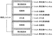
図1は、吸着プロセスの単純化された概略図である。供給ガスは、管4及びバルブ6を通し、入口7を通して、吸着層8の中に供給される。同時に、層8を通してガスを流すと共に、冷却剤はバルブ9を通って流れ、次に、吸着層8から熱を除去する熱交換器10を通る。低温で更に多くのガスが吸着されるので、また吸着は熱を発生させるので、冷却は必要である。吸着層で吸着されないガスは、出口12及びバルブ14を通って流れ出る。吸着サイクルの最後には、供給ガスは止められる。
DESCRIPTION OF PREFERRED EMBODIMENTS FIG. 1 is a simplified schematic diagram of an adsorption process. The supply gas is supplied into the
脱着モード時の装置は図1bに概略示してある。熱交換媒体制御バルブ9を切り替えて、熱交換器10の中に比較的熱い流体を通す。高温では更に多くのガスが脱着されるので、また脱着によって吸着層8が冷却されるので、熱が必要である。バルブ14を切り替えて、流れを向け直すことができ、所望ならば、脱着されたガスを捕集することができる。
The device in the desorption mode is schematically shown in FIG. 1b. The heat exchange
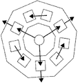
図2は螺旋状吸着メソチャンネル22を有する吸着層20のトップダウン図である。運転中、吸着メソチャンネル22は吸着媒体(図示されていない)を含む。熱交換流体ヘッダー24は、熱交換器チャンネルの多重層にへと流体を輸送できる。
FIG. 2 is a top-down view of the
吸着チャンネル22は様々な形状をとることができるが、螺旋形状はいくつかの用途にとって望ましいかもしれない。吸着チャンネルの高さ(高さは、図2のページから外の方向にあって、吸着チャンネルの底部から頂部まで測定される)は、1cm以下、更に好ましくは0.1 〜 10mm、なお更に好ましくは1 〜 5mmである。高さを調節することは重要である。なぜならば、熱輸送及び質量輸送のための時間を限定し、サイクル時間をより短縮できるからである。吸着チャンネル22の長さは、ガス入口からガス出口までの正味の流れの方向に存在していて、通常は、許され得る圧力低下と、他の考慮事項、例えば本発明が用いられることになる用途に基づいて決定される。チャンネルの長さに関しては制限はないが;ほとんどの用途のためには、吸着チャンネルの長さは、25cm以下、更に好ましくは10cm以下、なお更に好ましくは1 〜 6cmである。吸着チャンネル22の幅は、特定の態様の設計の関数でもあって、しばしば、内部設計の考慮事項、例えば吸着チャンネルの幅を画定して本発明の作製中に構造リブとして役立つ壁に関するニーズに基づいて決定される。幅は、一般的に、高さ及び長さに対して直角であり、流路の任意の横断面において測定され、好ましくは10cm以下、更に好ましくは5cm以下、又は、なお更に好ましくは5 〜 3cmである。
Although the
吸着層用の構造材料は、金属でもよいが、好ましくは例えばプラスチックのような低熱質量材料(low thermal mass material)である。吸着チャンネルに対する金属熱交換器インターフェイスと組合せたプラスチック吸着層は、時間の関数として脱着されるガスの部分として測定される脱着特性が優れ、このためにより速いサイクル時間が可能になることを見出した。好ましくは、チャンネルは、吸着層を貫通して完全に切り開かれ、吸着媒体は、好ましくは、2つの側面で熱交換器と接触する。吸着層が薄いと、デバイスサイズ、重量及び熱質量が減少する(更に迅速な温度スイングが可能になる)。 The structural material for the adsorption layer may be a metal, but is preferably a low thermal mass material such as plastic. It has been found that the plastic adsorption layer combined with the metal heat exchanger interface to the adsorption channel has excellent desorption properties measured as part of the gas desorbed as a function of time, which allows for faster cycle times. Preferably, the channel is cut completely through the adsorption layer and the adsorption medium is preferably in contact with the heat exchanger on two sides. A thin adsorbent layer reduces device size, weight, and thermal mass (allows more rapid temperature swings).
ガス吸着媒体(固体である)は、当業において公知であり、所望のガスに対する選択率を基準にして選択できる。二酸化炭素及び水蒸気に関しては、13Xゼオライトペレットは一つの好ましい例である。容量を最大にするためには、吸着チャンネルに存在する吸着媒体の量を最大にすることが望ましいが;質量輸送速度に関する制限とは二律背反であって、吸着チャンネルが更に完全に充填されると、所定の圧力低下においてガス流量が減少する。而して、粒子の間隙を通って流れ且つ拡散できるように、ペレット又は粒子を用いることが好ましい。他の好ましい吸着媒体の形態として、多孔質フロースルーフォーム、フェルト及びハニカムが挙げられる。好ましい態様では、吸着チャンネルは、50%超、更に好ましくは少なくとも80%充填される。吸着媒体は、吸着チャンネルの総体積の百分率として測定され、粒子及びその間隙は「充填されている」とみなされる。他の好ましい態様では、吸着媒体は、吸着チャンネルの少なくともある部分の横断面の少なくとも60%、更に好ましくは80%、なお更に好ましくは少なくとも90%を充填し、この方法では、短い吸着チャンネルでも通過する実質的にすべてのガスが吸着媒体と接触する。ガスを直接に吸着剤中に通す利点としては、加熱/冷却流を吸着媒体の両側に配置することができ、脱着がより小さい空隙中へと起こり、而して、(熱化学圧縮機用途のために)より大きな圧縮が提供されるので、吸着媒体に対して加熱及び冷却を提供する機会がより良好に与えられる点が挙げられる。吸着媒体に加えて、いくつかの好ましい態様では、吸着チャンネルは、例えばチャンネル壁から突出しているフィン又はピンのような熱交換体、又は例えばグラファイトもしくは金属繊維もしくは金属フレークのような散在された熱伝導性材料も含む。 Gas adsorption media (which are solid) are known in the art and can be selected based on the selectivity to the desired gas. For carbon dioxide and water vapor, 13X zeolite pellets are one preferred example. In order to maximize capacity, it is desirable to maximize the amount of adsorption medium present in the adsorption channel; however, contrary to the limitation on mass transport rate, if the adsorption channel is more fully packed, The gas flow rate decreases at a predetermined pressure drop. Thus, it is preferred to use pellets or particles so that they can flow and diffuse through the interstices of the particles. Other preferred adsorbent media forms include porous flow-through foams, felts and honeycombs. In a preferred embodiment, the adsorption channel is filled more than 50%, more preferably at least 80%. The adsorption medium is measured as a percentage of the total volume of the adsorption channel and the particles and their gaps are considered “filled”. In another preferred embodiment, the adsorption medium fills at least 60%, more preferably 80%, even more preferably at least 90% of the cross-section of at least some portion of the adsorption channel, and in this method it passes through even short adsorption channels. Substantially all of the gas that comes into contact with the adsorption medium. The advantage of passing the gas directly through the adsorbent is that a heating / cooling stream can be placed on both sides of the adsorption medium, and desorption occurs into smaller voids, thus (for thermochemical compressor applications). (For example) greater compression is provided, which gives better opportunities to provide heating and cooling to the adsorption medium. In addition to the adsorption medium, in some preferred embodiments, the adsorption channels are heat exchangers such as fins or pins protruding from the channel walls, or scattered heat such as graphite or metal fibers or flakes. Also includes conductive material.
本発明の装置は、好ましくは、吸着層と接触している少なくとも1つのマイクロチャンネル熱交換器を含む。「マイクロチャンネル」という用語は、1mm以下の少なくとも1本の寸法を有するチャンネルを指している。マイクロチャンネルは、好ましくは最大の高さ1mm及び幅10cm以下及び任意の長さ(高さはチャンネルを通過する流体流の方向である)を有し、更に好ましくは100 〜 500マイクロメートル(μm)の高さを有する。いくつかの好ましい構造では、各吸着層は熱交換器の間にサンドイッチされる。好ましくは、熱交換器層は、熱交換流体チャンネルと、その熱交換チャンネルと吸着層との間にある壁とを含んでいて、(吸着層(単数又は複数)への/からの熱輸送の方向において)200 〜 2000μmの厚さを有する。 The apparatus of the present invention preferably includes at least one microchannel heat exchanger in contact with the adsorption layer. The term “microchannel” refers to a channel having at least one dimension of 1 mm or less. The microchannel preferably has a maximum height of 1 mm and a width of 10 cm or less and any length (height is the direction of fluid flow through the channel), more preferably 100-500 micrometers (μm) Has a height of In some preferred structures, each adsorbent layer is sandwiched between heat exchangers. Preferably, the heat exchanger layer includes a heat exchange fluid channel and a wall between the heat exchange channel and the adsorption layer for heat transport to / from the adsorption layer (s). (In the direction) having a thickness of 200 to 2000 μm.
好ましくは、熱交換器は、高度に熱伝導性の材料から完全に又は少なくとも部分的に構成されており;熱交換構造にとっては低熱質量も望ましい。いくつかの好ましい態様では、熱交換器は、熱交換器層内において、ヘッダー(単数又は複数)及びフッター(単数又は複数)を接続している様々な長さのチャンネルを有していて;好ましくは、これらの異なる長さのチャンネルの体積は、熱流束が熱交換領域(熱交換器及び吸着剤へと/から熱が輸送される領域)全面で等しくなるように調節される。図11 〜 16に関する以下の考察を参照されたい。いくつかの好ましい態様では、熱交換器の高度に熱伝導性の材料は、好ましくは、吸着チャンネルとほぼ同じ形状を有する(例えば、螺旋形状の吸着チャンネルの上に及び/又は下にある螺旋形状の熱輸送材料)。なぜならば、この構造は、吸着媒体を選択的に加熱するように動作して、デバイスの他の部材、例えば吸着層の他の部分を加熱することが減り、また熱サイクル速度も速くなるかもしれないからである。いくつかの好ましい態様では、熱交換器の高度に熱伝導性の材料は、吸着チャンネル(単数又は複数)と少なくとも80%、更に好ましくは少なくとも90%オーバーラップしている。逆に、吸着チャンネル(単数又は複数)は、熱交換器の流体流部分の好ましくは少なくとも80%、更に好ましくは少なくとも90%とオーバーラップしている。「オーバーラップ」は、積み重なっている方向を見て、一つの要素上におけるもう一方の要素の重複像を計量することによって測定される。吸着チャンネルの形状に適合する螺旋構造に造形されている熱交換器に関してデバイスを試験したが、本発明者は、非熱伝導性材料から成る周囲領域を有する成形された熱伝導性マイクロチャンネル領域を有する熱交換器層も構想している。 Preferably, the heat exchanger is fully or at least partially constructed from highly thermally conductive material; a low thermal mass is also desirable for the heat exchange structure. In some preferred embodiments, the heat exchanger has channels of various lengths connecting the header (s) and footer (s) within the heat exchanger layer; The volume of these different length channels is adjusted so that the heat flux is equal across the heat exchange area (area where heat is transferred to / from the heat exchanger and adsorbent). See the discussion below regarding FIGS. In some preferred embodiments, the highly heat conductive material of the heat exchanger preferably has approximately the same shape as the adsorption channel (eg, a helical shape above and / or below the helical adsorption channel). Heat transport material). Because this structure operates to selectively heat the adsorption medium, it may reduce heating of other parts of the device, such as other parts of the adsorption layer, and may increase the thermal cycle rate. Because there is no. In some preferred embodiments, the highly heat conductive material of the heat exchanger overlaps the adsorption channel (s) by at least 80%, more preferably at least 90%. Conversely, the adsorption channel (s) preferably overlap at least 80%, more preferably at least 90% of the fluid flow portion of the heat exchanger. “Overlap” is measured by looking at the stacking direction and measuring the overlapping image of the other element on one element. Although the device has been tested on a heat exchanger that is shaped into a helical structure that conforms to the shape of the adsorption channel, the inventor has identified a shaped thermally conductive microchannel region having a peripheral region of non-thermally conductive material. A heat exchanger layer is also envisaged.
流体のためのチャンネルの代わりに又は流体のためのチャンネルに加えて、熱源は、電気抵抗ヒーター、光吸収表面又は放射性同位体を含むことができる。例えば発熱化学反応器(exothermic chemical reactor)又は原子力リアクターのような他のプロセス技術も熱源となり得る。吸着媒体と接触するガスの非吸着成分は、吸着中に熱を除去することもできるので、ヒートシンク又はヒートシンクの一部として役立つ。又は、熱源及び/又はヒートシンクは、それぞれ、吸着層からの低温熱を、脱着層のための高温熱へと上昇させるヒートポンプシステムの一部であってもよい。いくつかの態様では、他のプロセス技術からの廃熱が本発明装置のための熱源であるように、又は本発明装置のためのヒートシンクが、吸着中にもしくは吸着前に熱が除去されるおおよその温度において低温熱を必要とする別のプロセス技術であってもよいように、本発明装置は、低温廃熱を生成する他のプロセス技術と一緒に構成される。 Instead of or in addition to the channel for the fluid, the heat source can include an electrical resistance heater, a light absorbing surface or a radioisotope. Other process technologies such as exothermic chemical reactors or nuclear reactors can also be a heat source. The non-adsorbed component of the gas in contact with the adsorption medium can serve as a heat sink or part of a heat sink because it can also remove heat during adsorption. Alternatively, the heat source and / or heat sink may each be part of a heat pump system that raises low temperature heat from the adsorption layer to high temperature heat for the desorption layer. In some embodiments, waste heat from other process technologies is a heat source for the device of the present invention, or a heat sink for the device of the present invention is approximately removed of heat during or prior to adsorption. The apparatus of the present invention is configured in conjunction with other process technologies that produce low temperature waste heat, so that it may be another process technology that requires low temperature heat at this temperature.
熱交換器における熱輸送流体は好ましくは水であるが、任意の適当な伝熱流体を用いてもよい。例えば、液体金属、炭化水素ベース及びシリコーンベースの流体、多くのガス(例えば、空気、窒素、二酸化炭素又は水素)及び相転移流体(例えば、冷媒)も、本発明の様々な態様のための適当な熱伝達流体である。実施例のところで説明しているように、流量が多いと熱変化速度が増すので、サイクル時間が短縮するが;過度に流量が増加すると、熱力学的な不可逆性が増大するので、システムのエネルギー効率が低下することがある。 The heat transport fluid in the heat exchanger is preferably water, but any suitable heat transfer fluid may be used. For example, liquid metals, hydrocarbon-based and silicone-based fluids, many gases (eg, air, nitrogen, carbon dioxide or hydrogen) and phase change fluids (eg, refrigerants) are also suitable for various aspects of the invention. Heat transfer fluid. As explained in the examples, the higher the flow rate, the faster the rate of thermal change, thus reducing the cycle time; however, excessively increasing the flow rate increases the thermodynamic irreversibility, thus increasing the energy of the system. Efficiency may be reduced.
良好な熱輸送特性、コンパクトで且つ組み立て易いために、吸着層(単数又は複数)及び熱交換器(単数又は複数)は、部材が互いの頂部上に積み重なるように、平らな表面又は相補的な表面(鍵と鍵穴)を有することが好ましい。 For good heat transport properties, compact and easy to assemble, the adsorption layer (s) and the heat exchanger (s) are flat surfaces or complementary so that the members are stacked on top of each other It is preferable to have a surface (key and keyhole).
本発明の別の面では、熱交換流体を介する伝熱式熱交換が提供されるように吸着セルの一群を配置する。図3には、12個のメソチャンネル吸着セル(各セルは、吸着媒体を有する1本以上のメソチャンネルと、1つ以上の熱交換器とを有する)を用いるこのアプローチに関する一つの概略図が記載してある。システムのある部分は吸着であるが、別の部分は脱着であり、残りのセルは、熱交換流体を用いて、予熱(脱着のために)又は冷却(吸着のために)されている。脱着セル(単数又は複数)からの熱交換流体は、吸着剤を予熱している別のセル(単数又は複数)の中に入り、それと同時に、吸着セル(単数又は複数)の熱交換器からの熱交換流体は、吸着剤を予冷している別のセル(単数又は複数)の中に入る。熱交換流体は、各吸着/脱着セル内に埋設されているメソチャンネル中の経路をとることができると考えられる。このアプローチは、米国特許第5,419,156号(その内容を本明細書に引用したものとする)で説明されている概念と同様である。前記特許は、吸着圧縮機に関して全般的な概念を一般的に説明しているが、メソチャンネル又はマイクロチャンネルを用いる吸着/脱着に対して吸着圧縮機を適用していない。 In another aspect of the invention, a group of adsorption cells is arranged to provide heat transfer heat exchange via a heat exchange fluid. FIG. 3 shows one schematic diagram for this approach using twelve mesochannel adsorption cells, each cell having one or more mesochannels with an adsorption medium and one or more heat exchangers. It is described. One part of the system is adsorption, while another is desorption, and the remaining cells are preheated (for desorption) or cooled (for adsorption) using a heat exchange fluid. The heat exchange fluid from the desorption cell (s) enters another cell (s) preheating the adsorbent and at the same time from the heat exchanger of the adsorption cell (s) The heat exchange fluid enters into another cell or cells that are precooling the adsorbent. It is believed that the heat exchange fluid can take a path in mesochannels embedded within each adsorption / desorption cell. This approach is similar to the concept described in US Pat. No. 5,419,156, the contents of which are hereby incorporated by reference. The patent generally describes the general concept of adsorption compressors, but does not apply adsorption compressors to adsorption / desorption using mesochannels or microchannels.
熱回収も、吸着に基づく吸着ポンプによって達成できる。例えば、図3の概略図は、マルチセルメソチャンネル吸着ポンプに関する一つの可能な概念を図示している。そのサイクルは、Sywulkaに与えられた米国特許第5,419,156号で説明されているサイクルと同様である。概念的には、セルは、サイクル中は時計回りに移動するが、伝熱流体は、各セル中に存在する伝熱チャンネル中を反時計回りに循環する。脱着が起こっている図の上部にあるセルでは、温度が最も高くなっている。伝熱流体が最も温度が高いこの段階を出るとき、伝熱流体は、脱着工程の方へとサイクルしている左側にあるセルに対して熱を連続的に捨てる。下部では、最低温度のセルが吸着している。伝熱流体がセルを通って右側に上がると、該流体は、脱着工程の方へと下がっているセルを冷却する。この様式で、熱質量と関係がある熱の大部分は、有効に回収される。脱着器では、いくらかの熱を提供し、吸着器では除去して、システムを、圧縮仕事を行なう熱エンジンとして動作させなければならない。実際には、セルは物理的に回転させることはできないことに留意されたい。仮想の回転は、入口及び出口のポイントならびに加熱と冷却が起こるポイントを移行させることによって達成できる。 Heat recovery can also be achieved by adsorption pumps based on adsorption. For example, the schematic diagram of FIG. 3 illustrates one possible concept for a multi-cell mesochannel adsorption pump. The cycle is similar to the cycle described in US Pat. No. 5,419,156 to Sywulka. Conceptually, the cells move clockwise during the cycle, but the heat transfer fluid circulates counterclockwise through the heat transfer channels present in each cell. In the cell at the top of the figure where desorption occurs, the temperature is highest. As the heat transfer fluid exits this stage of the highest temperature, the heat transfer fluid continuously dissipates heat to the left cell that is cycling towards the desorption process. At the bottom, the lowest temperature cell is adsorbed. As the heat transfer fluid rises to the right through the cell, the fluid cools the cell down toward the desorption process. In this manner, most of the heat associated with the thermal mass is effectively recovered. The desorber provides some heat and the adsorber removes it, and the system must operate as a heat engine that performs the compression work. Note that in practice, the cell cannot be physically rotated. Virtual rotation can be achieved by shifting the entry and exit points and the points where heating and cooling occurs.
Sywulkaの概念では、実質的な量のバルビング(a substantial amount of valving)が必要である。熱回収メソチャンネル吸着ポンプのための流体ポンプ及びバルブは、吸着ポンプ構造内にバルブを埋設することによって、又は前記構造に接続されている導管に対して外部バルブを接触することによって、提供できる。 The Sywulka concept requires a substantial amount of valving. Fluid pumps and valves for heat recovery mesochannel adsorption pumps can be provided by embedding valves in the adsorption pump structure or by contacting an external valve to a conduit connected to the structure.
熱回収に関する他のオプションはマルチセル吸着ポンプであり、該吸着ポンプの全般的な目的は、冷却しているセルからの熱エネルギーを利用することであり、吸着を支援することであり、及び加熱を必要とする別のセルに対して熱を提供して脱着を支援することである。図4a 〜 4fに示してあるように、Sywulkaの連続流体プロセスループは、各セルと直ぐ隣に存在するセルとの間の熱接続で代替される。熱接続は、熱交換流体ループを用いて、又は例えば熱スイッチを用いることによって作ることができる。また、流体ポンプ及びバルブを内部又は外部に提供することができる。 Another option for heat recovery is a multi-cell adsorption pump, the general purpose of which is to utilize thermal energy from the cooling cell, to support adsorption, and to heat It is to provide heat to another cell that needs it to aid desorption. As shown in FIGS. 4a-4f, Sywulka's continuous fluid process loop is replaced with a thermal connection between each cell and the immediately adjacent cell. The thermal connection can be made using a heat exchange fluid loop or by using, for example, a thermal switch. Also, fluid pumps and valves can be provided inside or outside.
エネルギー効率の良い運転では、伝熱式熱交換が高度に効率が良いことが必要である。熱交換チャンネル及び吸着チャンネルは、システムを運転することに関わる熱エネルギーの少なくとも60%以上、又は更に好ましくは80%以上、なお更に好ましくは90%が回収されるように、共同して働く。 In energy efficient operation, heat transfer heat exchange needs to be highly efficient. The heat exchange channel and the adsorption channel work together so that at least 60% or more, more preferably 80% or more, and even more preferably 90% of the thermal energy involved in operating the system is recovered.
別の装置は図4a 〜 4fに概略示してある。好ましくは、このスキームでは、3の倍数個のセルを利用する。図示されているデバイス(各図は上から見下ろしている図である)は、9個のセルを含み、各セルは箱型で表してある。図4aでは、熱は、矢印42で示してある経路に沿って熱源40からセル44中に伝達される。熱源40は、例えば、パイプを通過する熱流体、光吸収表面、抵抗器、又は放射性同位体を有する容器、又は別のプロセス技術から熱流を提供する熱スイッチもしくは他の熱導管を含むことができると考えられる。サイクルの最も高い温度で動作するセル44は、ガス46を脱着し、脱着されたガスはバルブ付出口(図示されていない)を通って出る。同時に、温セル48は、隣接している冷セル50に対して熱49を伝達する。
Another apparatus is shown schematically in FIGS. Preferably, this scheme utilizes multiples of 3 cells. The device shown (each figure is a view looking down from above) includes nine cells, each cell being represented by a box. In FIG. 4 a, heat is transferred from the
図4bに図示してある次の工程では、セル44の出口は閉じられ、セル44からの熱51が移動されて、隣接セル50を温める。同時に、ガス52はセル48に吸着され、熱54はヒートシンク(図示されていない)へと伝達される。そのヒートシンクは、例えば、熱交換器中の冷却流体、ほぼ吸着温度もしくは吸着温度を下回る温度において熱を要求する別のプロセス技術、又は単純に大気であることができると考えられる。
In the next step illustrated in FIG. 4b, the outlet of the
図4cに図示してある次の工程では、熱源からの熱は、吸着されたガスを脱着させるセル50へと伝達される。同時に、温セル44は隣接冷セル48へと熱を伝達する。
図4dに図示してある次の工程では、セル50の出口は閉じられ、セル50からの熱は伝達されて、隣接セル48を温める。同時に、ガス52はセル44で吸着され、熱54はヒートシンク(図示されていない)へと伝達される。次の工程は図4e及び4fに示してある。
In the next step illustrated in FIG. 4c, heat from the heat source is transferred to the
In the next step illustrated in FIG. 4d, the outlet of the
また、本発明は、吸着層(単数又は複数)と熱交換器とを結合させることを含む吸着装置を作製する方法も含む。すべて金属製のユニットでは、結合は、好ましくは拡散結合によるものである。プラスチック含有ユニットは、接着剤、圧縮取り付け、拡散、又は他の方法によって結合させることができる。また、装置は、セラミックを含むか又はセラミックから組み立てることができ、また様々な方法でシールすることができる。 The present invention also includes a method of making an adsorption device that includes coupling an adsorption layer (s) and a heat exchanger. In all metal units, the coupling is preferably by diffusion bonding. Plastic-containing units can be joined by adhesives, compression fitting, diffusion, or other methods. Also, the device can include or be assembled from ceramic and can be sealed in various ways.
本発明のすべてのガス吸着法は、ガスを吸着媒体上へと吸着し、次に吸着させる工程を含む。ある面では、ガスは、吸着媒体を含むチャンネル中に通され(好ましくは、最初に接触器中を通過させることなく)、それと同時に、熱は、熱交換器へと、又は熱交換器から、約1cm未満の正味の距離のところに存在する吸着媒体の任意のポイントへと輸送される。言い換えれば、吸着剤のすべてのポイントは、熱交換器から約1cm以下の距離内にある。正味の効果は、ガスが濃縮又は圧縮されることであり、プロセスのためのエネルギーは熱エネルギー(熱)である。熱源及びヒートシンクが要求されるので、熱力学サイクルは、熱エンジンのそれである。更に、熱及び質量の輸送距離が短いので、マイクロチャンネル及び/又はメソチャンネルの最も短い寸法に沿って、システムは速いサイクル速度で動作する。吸着媒体の任意のポイントから最も長い熱輸送距離は、約1cm未満であり;更に好ましくは約8mm未満であり、なお更に好ましくは5mm未満である。いくつかの場合では、熱輸送距離はもっと長くてもよい。熱輸送を増強するために、多孔質導体を吸着チャンネル中に配置できると考えられる。別の面では、熱は、選択的に加えられそして、吸着層の他の部分への伝熱が比較的低いレベルである吸着層から選択的に除去される。更に別の面では、熱は、高い熱伝導性材料から成る熱交換器と、比較的低い熱伝導性材料から成る吸着層との間で伝達される。 All gas adsorption methods of the present invention include the steps of adsorbing gas onto an adsorption medium and then adsorbing it. In one aspect, the gas is passed through a channel containing an adsorption medium (preferably without first passing through the contactor), while heat is transferred to or from the heat exchanger at the same time. It is transported to any point on the adsorption medium that is present at a net distance of less than about 1 cm. In other words, all points of the adsorbent are within a distance of about 1 cm or less from the heat exchanger. The net effect is that the gas is concentrated or compressed and the energy for the process is thermal energy (heat). Since a heat source and a heat sink are required, the thermodynamic cycle is that of a heat engine. Furthermore, due to the short heat and mass transport distances, the system operates at high cycle rates along the shortest dimension of the microchannels and / or mesochannels. The longest heat transport distance from any point on the adsorption medium is less than about 1 cm; more preferably less than about 8 mm and even more preferably less than 5 mm. In some cases, the heat transport distance may be longer. It is believed that a porous conductor can be placed in the adsorption channel to enhance heat transport. In another aspect, heat is selectively applied and selectively removed from the adsorption layer where heat transfer to other parts of the adsorption layer is at a relatively low level. In yet another aspect, heat is transferred between a heat exchanger made of a highly thermally conductive material and an adsorption layer made of a relatively low thermally conductive material.
更にもう一つ別の面では、ガスは、圧力スイングによって、吸着チャンネル中にある吸着剤から脱着される。熱交換器は圧力スイング吸着には必要ではないが、速さ及び/又は容量を増強するためには熱交換器が存在できると考えられる。 In yet another aspect, the gas is desorbed from the adsorbent in the adsorption channel by a pressure swing. A heat exchanger is not required for pressure swing adsorption, but it is believed that a heat exchanger can be present to increase speed and / or capacity.
また、本発明は、プロセスにおける工程として本発明のガス吸着法を含むガス分離法も含む。例としては、呼気からのCO2の分離、天然ガスを「仕上げる」ために天然ガスからH2Sを除去すること、燃料電池発電所のために水素富化流から(例えば、改質装置から)CO2及び/又はCOを除去すること、(空気を乾燥させるために)空気から水を除去すること、及び更に複雑な分離が挙げられ、その場合、吸着デバイスは、例えば機器用途のためのようにアルゴン又は窒素を精製するためのような、プロセスの一部分ではない。 The present invention also includes a gas separation method including the gas adsorption method of the present invention as a process step. Examples include separation of CO 2 from exhaled air, removal of H 2 S from natural gas to “finish” the natural gas, from a hydrogen enriched stream for a fuel cell power plant (eg, from a reformer) ) Removing CO 2 and / or CO, removing water from the air (to dry the air), and more complex separations, in which case the adsorption device is for example for instrument applications Is not part of the process, such as for purifying argon or nitrogen.
サイズ、組成などに関して本発明を説明することとは別に又は説明することに加えて、本発明は、他の測定可能な特性、例えば迅速なサイクル性(cyclability)及びハードウェア体積の関数としてのガス吸着/脱着について説明することができる。 In addition to or in addition to describing the present invention with respect to size, composition, etc., the present invention provides other measurable characteristics, such as rapid cyclability and gas as a function of hardware volume. Adsorption / desorption can be described.
細い吸着チャンネルを用いると、伝熱(伝熱出力密度として表すことができる)を更に速くすることができる。迅速なサイクリングを可能にするために、熱は、吸着チャンネルと熱交換チャンネルとの間で、1立方センチメートルあたり少なくとも0.5ワットの速度で、更に好ましくは1立方センチメートルあたり少なくとも1.0ワットを超える速度で、なお更に好ましくは1立方センチメートルあたり少なくとも5.0ワットを超える速度で交換される。前記の値は、既に上で規定したように体積は吸着セル体積であって、完全な冷却加熱サイクルに関して測定される。本発明における伝熱の上限は、吸着層の厚さが0に近づくにつれて限定される。いくつかの好ましい態様では、伝熱速度は、約1.0 〜 6.0W/ccである。好ましい方法では、吸着剤の理論容量の少なくとも50%、更に好ましくは少なくとも80%、なあ更に好ましくは少なくとも95%は、3分間、更に好ましくは1分間、なお更に好ましくは20秒以下の熱スイングサイクル(真空を施用しない又はパージガスもしくはスイープガスを加えない)で利用され、いくつかの態様では3分 〜 30秒の熱スイングサイクルで利用される。 Use of a narrow adsorption channel can further increase heat transfer (which can be expressed as heat transfer power density). In order to allow rapid cycling, the heat is between the adsorption and heat exchange channels at a rate of at least 0.5 watts per cubic centimeter, more preferably at least above 1.0 watt per cubic centimeter. And even more preferably exchanged at a rate of at least greater than 5.0 watts per cubic centimeter. The values are measured for complete cooling and heating cycles, where the volume is the adsorption cell volume as already defined above. The upper limit of heat transfer in the present invention is limited as the thickness of the adsorption layer approaches zero. In some preferred embodiments, the heat transfer rate is from about 1.0 to 6.0 W / cc. In a preferred method, a thermal swing cycle of at least 50%, more preferably at least 80%, even more preferably at least 95% of the theoretical capacity of the adsorbent is 3 minutes, more preferably 1 minute, even more preferably 20 seconds or less. (No vacuum applied or purge gas or sweep gas added), and in some embodiments, a thermal swing cycle of 3 minutes to 30 seconds.
いくつかの好ましい態様では、本発明装置は、吸着媒体を等体積の13Xゼオライト(1立方センチメートルあたり0.67gのかさ密度を有する)で置換する場合、このゼオライトを、760mmHg及び5℃において二酸化炭素で飽和させ、次に、760mmHgにおいて出力を保ちながら(熱交換器(単数又は複数)中に90℃の水を通すことによって)90℃まで温め、次に、ゼオライトの理論容量の少なくとも50%が1分以内に脱着されるような迅速な脱着能力を有する。更に好ましくは、吸着された二酸化炭素の少なくとも70%、なお更に好ましくは少なくとも90%は1分以内に脱着される。また、本発明は、生産性によって特徴付けられる。別の試験では、上記したものと同じ条件下で、装置1mlあたり少なくとも0.015gのCO2、更に好ましくは少なくとも0.025g、いくつかの態様では0.015 〜 約0.04gのCO2が1分以内に脱着される。本発明の迅速な脱着能力は、一般的に、吸着媒体のタイプに影響されない;このような本発明のある種の態様を特徴付ける目的は、ハードウェアの設計を特徴付けるために、而して、本発明の迅速な脱着特性を特徴付けるために用いることができる測定可能な判定基準を提供することにある。 In some preferred embodiments, the apparatus of the present invention allows the zeolite to be replaced with carbon dioxide at 760 mm Hg and 5 ° C. when the adsorption medium is replaced with an equal volume of 13 × zeolite (having a bulk density of 0.67 g per cubic centimeter). Saturate and then warm to 90 ° C. (by passing 90 ° C. water through the heat exchanger (s)) while maintaining power at 760 mmHg, then at least 50% of the theoretical capacity of the zeolite is 1 It has a quick desorption ability that can be desorbed within minutes. More preferably, at least 70%, even more preferably at least 90% of the adsorbed carbon dioxide is desorbed within 1 minute. The invention is also characterized by productivity. In another study, under the same conditions as those described above, device 1ml per at least 0.015 g CO 2, more preferably at least 0.025 g, some embodiments are 0.015 to about 0.04g of CO 2 Desorbed within 1 minute. The rapid desorption capability of the present invention is generally not affected by the type of adsorption medium; the purpose of characterizing certain aspects of the present invention is to characterize the design of the hardware and thus It is to provide a measurable criterion that can be used to characterize the rapid desorption characteristics of the invention.
好ましい態様では、本発明は、吸着媒体の理論容量の少なくとも70%(更に好ましくは約80% 〜 約95%)が少なくとも2つの連続吸着脱着サイクルにおいて用いられるような迅速なサイクル性を有する。前記各サイクルは、総ガス量が理論容量(時間が無限大のときの吸着剤の容量)の1.5倍に等しくなるような流量で、各サイクルの吸着部分のために、1分間、吸着チャンネル中にパージガスを通し、それと同時に、10℃の水を、熱交換器中に通し、次に、そのガス流を止め、各サイクルの脱着部分のときに、1分間、熱交換器(単数又は複数)中に90℃の水を通すことによって、吸着層(単数又は複数)を加熱する試験によって測定すると、2分間で達成される。この測定では、選択された吸着媒体のための典型的な標的ガスに適合するようにパージガスを選択すべきである。この迅速なサイクリングは、真空を施用せず且つパージガス又はスイープガスを加えない純粋な熱スイング吸着によって得られる。 In a preferred embodiment, the present invention has rapid cyclability such that at least 70% (more preferably from about 80% to about 95%) of the theoretical capacity of the adsorption medium is used in at least two successive adsorption / desorption cycles. Each cycle has a flow rate such that the total gas volume is equal to 1.5 times the theoretical capacity (the capacity of the adsorbent when the time is infinite), and for 1 minute for the adsorption part of each cycle. Purge gas is passed through the channel and at the same time, 10 ° C. water is passed through the heat exchanger, then the gas flow is stopped and the heat exchanger (single or This is achieved in 2 minutes as measured by the test of heating the adsorption layer (s) by passing water at 90 ° C. through the plurality. For this measurement, the purge gas should be selected to match the typical target gas for the selected adsorption medium. This rapid cycling is obtained by pure thermal swing adsorption without applying a vacuum and adding no purge or sweep gas.
また、本発明のシステムは、優れた安定性も示すことができ、好ましい態様では、生産性は、100サイクル後でも10%未満低下するだけである。
典型的な用途では、複数の吸着層を複数の熱交換器層と交互に配置して単一ユニットにする。好ましくは、一体化されたユニットは、2つの熱交換器の間に各吸着層をサンドイッチしている。更に好ましくは、ユニットは少なくとも5つの吸着層及び6つの熱交換器層を含む。いくつかの態様では、51の熱交換器と交互に配置された少なくとも50の吸着層を含むユニットによってより大量のガスを分離することができる。
The system of the present invention can also exhibit excellent stability, and in a preferred embodiment, productivity is only reduced by less than 10% even after 100 cycles.
In a typical application, multiple adsorption layers are interleaved with multiple heat exchanger layers to form a single unit. Preferably, the integrated unit sandwiches each adsorption layer between two heat exchangers. More preferably, the unit comprises at least 5 adsorption layers and 6 heat exchanger layers. In some embodiments, a greater amount of gas can be separated by a unit comprising at least 50 adsorbent layers interleaved with 51 heat exchangers.
好ましい態様では、メソチャンネル吸着セルは、結合後に吸着媒体を加えたり除去できるように設計される。吸着チャンネル(単数又は複数)は、熱交換チャンネルに比べて、より長く作ることができるか又は片側に付け加えて配置できる。この設計では、セルは(例えば、切ったり又はボルトを取り除くことによって)開けることができ、熱交換チャンネルを開けなくても吸着媒体を取り出したり且つ/又は加えたりできる。ユニットは、溶接、圧縮固定又は他の方法によって再シールされる。 In a preferred embodiment, the mesochannel adsorption cell is designed so that the adsorption medium can be added or removed after binding. The adsorption channel (s) can be made longer than the heat exchange channel or can be arranged in addition to one side. In this design, the cell can be opened (eg, by cutting or removing bolts), and the adsorption medium can be removed and / or added without opening the heat exchange channel. The unit is resealed by welding, compression fixing or other methods.
図5には宇宙飛行士などのための空気処理システムが図示してある。水吸着器はシリカゲル、又はゼオライト、又は他の適当な吸着剤を含むことができ;同様に、CO2吸着器はゼオライト又は他の好ましい吸着剤を含むことができる。吸着されるそれぞれの種(例えば、水及びCO2)のために、2種類の吸着セルが存在し、一つは、処理のために所定の時間用いられる吸着セルであり、もう一つは、熱を添加することによって再生されている吸着セルである。好ましい態様では、システムは、それぞれの種のための複数の吸着セルから成っていて、改良された熱回収を提供する。同じ吸着媒体を用いる非再生システムに比べて、同時再生を行なうと、要求される吸着剤質量は減少する。要求される質量及び体積は、サイクル時間が短くなるにつれて線形的に減少する。典型的な4時間の運転のために、4分のサイクルで再生されるシステムでは、従来の非再生システムに比べて、要求される吸着剤量は約1/60未満である。 FIG. 5 shows an air treatment system for an astronaut or the like. The water adsorber can contain silica gel, or zeolite, or other suitable adsorbent; similarly, the CO 2 adsorber can contain zeolite or other preferred adsorbent. There are two types of adsorption cells for each species to be adsorbed (eg, water and CO 2 ), one is an adsorption cell that is used for a predetermined time for processing, and the other is It is an adsorption cell regenerated by adding heat. In a preferred embodiment, the system consists of multiple adsorption cells for each species, providing improved heat recovery. Compared to a non-regenerating system using the same adsorbing medium, the required adsorbent mass is reduced when simultaneous regeneration is performed. The required mass and volume decreases linearly as the cycle time decreases. For a typical 4 hour run, a system that is regenerated in a 4 minute cycle requires less than about 1/60 of the amount of adsorbent compared to a conventional non-regenerated system.
特に好ましいマルチセル吸着ポンプは図11 〜 16に図示してある。単一フローバイセルにおける単一フローバイユニットの横断面概略図は図11に示してある。面と面を接触させて積重ねられた一対のシムAは熱交換器を形成し;シムBそれぞれはシムを通過して吸着メソチャンネルを創出しているチャンネルを有し;シムCはガス流チャンネルを提供し;及びシムDそれぞれは、吸着剤とガス流チャンネルとの間に拡散質量輸送を可能にする多孔質接触器である。A,B,及びDがそれぞれ2つ及びCが1つである7つのシムによって繰返しユニットが創出される。言い換えると、複数の繰返しユニットを積重ねると、吸着セル中において、吸着チャンネルの数と吸着剤体積とが垂直方向に増大し、熱及び質量の輸送効率において不利益は無い。そのようなセルにおけるシムの適当な設計及び結合によって、熱交換流体は、吸着剤と吸着ガスとを含むチャンネルから密閉隔離される。 Particularly preferred multi-cell adsorption pumps are illustrated in FIGS. A schematic cross-sectional view of a single flow-by unit in a single flow-by-cell is shown in FIG. A pair of shims A stacked face to face form a heat exchanger; each shim B has a channel passing through the shim to create an adsorption mesochannel; shim C is a gas flow channel And Shim D are each a porous contactor that allows diffusion mass transport between the adsorbent and the gas flow channel. A repeating unit is created by seven shims with two A, B and D and one C respectively. In other words, when a plurality of repeating units are stacked, the number of adsorption channels and the adsorbent volume increase in the vertical direction in the adsorption cell, and there is no disadvantage in heat and mass transport efficiency. By proper design and coupling of shims in such a cell, the heat exchange fluid is hermetically isolated from the channel containing the adsorbent and adsorbed gas.
図12は、平面図で示された八角形対称(octagonal symmetry)の8セルフローバイ吸着器のための4つのシム設計を図示しており、図13は、同じシムの斜視図である。好ましくは、多孔質接触器120のためのシム材料(例えば、チタン)は、パターンをエッチングすることによって二次加工されて、メッシュ様のパターンを創出する孔及び/又は肋状組織(ribbing)を提供する。この二次加工は、光化学エッチング又は他の公知の手段によって達成できる。シムの台形オクタントのそれぞれの内にある2つの三角形のカットアウト170、171は、繰返しユニット及びセルのための熱交換流体ヘッダー及びフッターを形成する。
FIG. 12 illustrates four shim designs for an octagonal symmetry 8-cell flow-by adsorber shown in plan view, and FIG. 13 is a perspective view of the same shim. Preferably, the shim material (eg, titanium) for the
図12及び13は、フローバイ吸着器のための繰返しユニットの積層順序を示している。フロースルーデバイスは、繰返しユニットからガス流と多孔質接触器シムC及びDとを除去することによって、図11 〜 13で規定されたシムから容易に得られる。そのユニットは、望ましい容量のために、例えば、少なくとも2、少なくとも12又は2 〜 100の繰返しユニットを繰返して積重ねることができる。好ましくは、更に1本の熱交換チャンネルを、繰返しユニットスタック(repeat unit stack)の各末端で用いて、熱交換チャンネルの末端をキャップする。 Figures 12 and 13 show the stacking sequence of the repeating units for the flow-by adsorber. The flow-through device is easily obtained from the shim defined in FIGS. 11-13 by removing the gas flow and porous contactor shims C and D from the repeat unit. The unit can be stacked repeatedly, for example, at least 2, at least 12 or 2 to 100 repeating units for the desired capacity. Preferably, one more heat exchange channel is used at each end of the repeat unit stack to cap the end of the heat exchange channel.
結合された形態のデバイスの構造は図14に示してある。吸着ガスヘッダー/フッタープレート160を機械加工し取り付けると、図14の結合構造は図15に示した8セル吸着器にすることができる。エンドプレート140は、結合プロセスで有益であり、熱交換流体のための外部ヘッダーフッター接続のために用いることができる。典型的な製造プロセスでは、シムを積層し(好ましくは、拡散結合によって)、その側面は、切り離され、吸着剤を吸着チャンネル中に挿入する。次に、プレート160で開放面をキャップし、それを溶接することができる。好ましくは、プレート160は、吸着層の中に及び吸着層の外へとガス流を指向するヘッダー及びフッター(図示されていない)を含む。結合後にエンドプレートから材料の有意な部分(fraction)を除去することは、2つの機能に役立つ:すなわち、第一はデバイス質量を減少させること、第二は熱サイクル中にデバイス質量を加熱し冷却する仕事を減少させることに役立つ。後者は、エンドプレート材料が熱伝導性であって、大きな熱容量を有する場合は、特に重要である。冷却され加熱される吸着剤以外の他の構造の質量が減少する場合、又は熱エネルギーがサイクルからサイクルまで効率的に回収される場合、冷から熱から冷などのセルの熱サイクリングと関係があるエネルギー損失が最少化される。
The structure of the combined form of the device is shown in FIG. When the adsorbed gas header /
いくつかの態様では、吸着器の「熱質量」を更に最小化するために、また結合された金属によって提供される耐久性を維持するために、ステンレス鋼に比べてより低密度でより熱容量が低い材料、例えばチタンを用いることが望ましい。チタンは、ステンレス鋼の体積を基準にすると、密度はほぼ半分であり、熱容量もほぼ半分である。 In some embodiments, lower density and more heat capacity compared to stainless steel to further minimize the “thermal mass” of the adsorber and to maintain the durability provided by the bonded metal. It is desirable to use a low material such as titanium. Titanium has almost half the density and almost half the heat capacity based on the volume of stainless steel.
フローバイ吸着ポンプの特に好ましい態様では、ガスは入口111を通り、(好ましくは吸着層の全高まで延びている)壁115の周囲を流れ、そして吸着されていないガスは出口117を通って流れ出る。入口及び出口は、結合された装置の8つの側面のそれぞれから壁119を除去することによって、創出される。ガスは、多孔質接触器120を通って、チャンネル118中に含まれている吸着剤中に又は吸着剤から外へ拡散する。好ましくは、吸着層中にある全空間118は吸着剤で充填される。熱交換流体は導管152を経て熱交換ヘッダー中に流れ、そして各セルに取り付けられている導管154を経て熱交換フッターから出る。ガスは、プレート160において導管156を通って、装置中に存在するセルの中に流れ、そして導管158を通ってセルから出る。いくつかの好ましい態様では、ガス流及び熱交換流体流は、同じ一体化マルチセルデバイス内で一つのセルから別のセルへと送られる。そのルーティング(routing)は、本明細書の他の部分で提供されるマルチセル運転の説明にしたがって指示される。
In a particularly preferred embodiment of the flow-by adsorption pump, gas flows through the
熱交換シムAの詳細は図16に示してある。平らな熱伝達表面は吸着層と接触している。シムソリッドオーバーラップ(shim solids overlap)がオーバーラップしている領域において、前記表面と吸着シムBとを効果的に結合(例えば、金属の場合は拡散結合)させると、熱交換チャンネル中にある流体から、吸着層内にある吸着剤とガスとが密閉隔離される。 Details of the heat exchange shim A are shown in FIG. The flat heat transfer surface is in contact with the adsorption layer. When the surface and the adsorption shim B are effectively combined (for example, diffusion bonding in the case of metal) in the region where the shim solids overlap, the fluid in the heat exchange channel Thus, the adsorbent and gas in the adsorption layer are hermetically isolated.
図16は、同じ熱交換シムの他の表面を示していて、その表面では、熱交換流体チャンネル及びフィンを表面改質(例えば、光化学エッチング)することによって画定できる。この場合では、図面のハッチングされた領域は、例えば、シムの厚さの半分である深さ0.005インチ(0.125mm)でエッチング(又は機械加工又はスタンプ)できる。ハーフエッチングされた部分は流体チャンネル174を画定し、各チャンネルの間にあるエッチングされない材料は熱伝達フィン173である。
FIG. 16 shows another surface of the same heat exchange shim, which can be defined by surface modification (eg, photochemical etching) of the heat exchange fluid channels and fins. In this case, the hatched area of the drawing can be etched (or machined or stamped), for example, at a depth of 0.005 inch (0.125 mm), which is half the thickness of the shim. The half-etched portions define
図16で認められるように、フィンは、台形の内側(より小さい)エッジの方へより広くなっていて、チャンネルはより狭くなっている。この設計の特徴により、吸着層と、吸着層に隣接している支持構造とに対して、ほとんど一定の熱束を提供する。その設計は、熱伝達領域全体にわたって一定の熱束を可能にする。前記熱伝達領域は、最も広い流体チャンネルによって外側エッジ上に、最も狭い流体チャンネルによって内側エッジ上に、及び三角形の流体ヘッダー及びフッター170,171によって末端上に結合されている。而して、いくつかの好ましい態様では、熱交換器は、複数の(好ましくは、少なくとも6、更に好ましくは少なくとも16)の熱交換チャンネル(好ましくは、マイクロチャンネル)を含む。その熱交換チャンネルにおいては、そのチャンネルは、セル部材の外側(より大きな)エッジの方へとより広く及び/又はより深くなっている。 As can be seen in FIG. 16, the fins are wider toward the inner (smaller) edge of the trapezoid and the channels are narrower. This design feature provides an almost constant heat flux for the adsorption layer and the support structure adjacent to the adsorption layer. The design allows for a constant heat flux throughout the heat transfer area. The heat transfer area is coupled on the outer edge by the widest fluid channel, on the inner edge by the narrowest fluid channel, and on the end by triangular fluid headers and footers 170,171. Thus, in some preferred embodiments, the heat exchanger includes a plurality (preferably at least 6, more preferably at least 16) heat exchange channels (preferably microchannels). In the heat exchange channel, the channel is wider and / or deeper towards the outer (larger) edge of the cell member.
様々なチャンネル及びフィンの幅に関するニーズは、ヘッダー及びフッターを接続する流体チャンネルの長さに起因している。ヘッダー及びフッターは比較的大きく且つ開放しているので、ヘッダー及びフッターそれぞれの中の圧力は実質的に一定である。言い換えると、ヘッダー又はフッター内を流れている流体の圧力低下は、ヘッダー及びフッターを接続するチャンネル中を流れている流体の圧力低下に比して、無視できる。ヘッダー内の一定の流体圧力と、フッター中のより低い一定の圧力とを仮定すると、接続長方形チャンネルにおける体積流量は、圧力差(ΔP)、流体粘度、及びチャンネル長、幅及び高さの関数である。そこで、チャンネルの高さは、エッチングの深さによって画定され、一定と考えられるが、二次加工されるユニットで変化させることができる。チャンネル幅が一定である場合、流量は最も短いチャンネル(台形の内側エッジ上にある)で最も多くなる。流量が多くなると共に、チャンネル内の流体で運ばれる熱容量はより大きくなり、そして比較的高い熱束により、チャンネルに隣接している局所的な熱伝達領域が生じる。而して、チャンネルを通る体積流量を減少させるために、また熱伝達領域全体にわたって一定の熱束を提供するために、最も短いチャンネルをより狭くすることが望ましい。熱は、吸着層へ、及びフィンならびに流体チャンネルに(の上に又はの下に)隣接している関連構造要素へ伝達されるので、フィン幅も変化する。フィンそれら自体が、考慮しなければならない熱質量を有し、またフィンは、熱交換流体チャンネルによって与えられる局所的な熱伝達領域(及び総熱質量)を画定するのに役立つ。 The need for various channel and fin widths stems from the length of the fluid channel connecting the header and footer. Since the header and footer are relatively large and open, the pressure in each of the header and footer is substantially constant. In other words, the pressure drop of the fluid flowing in the header or footer is negligible compared to the pressure drop of the fluid flowing in the channel connecting the header and footer. Assuming a constant fluid pressure in the header and a lower constant pressure in the footer, the volume flow in the connecting rectangular channel is a function of pressure difference (ΔP), fluid viscosity, and channel length, width and height. is there. Thus, the height of the channel is defined by the depth of the etch and is considered constant, but can be varied in the secondary processed unit. If the channel width is constant, the flow rate is highest in the shortest channel (on the inner edge of the trapezoid). As the flow rate increases, the heat capacity carried by the fluid in the channel increases, and the relatively high heat flux creates a local heat transfer area adjacent to the channel. Thus, it is desirable to make the shortest channel narrower in order to reduce the volume flow through the channel and to provide a constant heat flux throughout the heat transfer area. As heat is transferred to the adsorbent layer and to the associated structural elements adjacent to (above or below) the fins and fluid channels, the fin width also changes. The fins themselves have a thermal mass that must be considered, and the fins serve to define the local heat transfer area (and total thermal mass) provided by the heat exchange fluid channel.
8セル部材178は中心軸172の周囲に配置される。説明のために、各セル部材は、任意の数の領域を有するものとして見ることができる;例えば、セル部材178は、フィン179によって分離された2つの領域、すなわち、熱交換流路(この場合は、9つの熱交換チャンネル)の少なくとも一部を含む中心軸方向に向かっている側面上にある第一領域と、熱交換流路(この場合は、8つの熱交換チャンネル)の少なくとも一部を含む装置の外側エッジ方向に向かっている第二領域へと分割されたものとして見ることができる。位置合せ穴176を有する位置合せタブ175は、シムを結合させて積層デバイスを形成した後で除去される。図示されている装置は、温度をモニターするためのアクセスポート177を含む。
The 8-
特定の態様が図11 〜 16に示してあるが、(1)本明細書の他のところで考察したファクター(例えば、好ましい吸着剤タイプ及び厚さ、運転条件など)のすべてがマルチセル態様に対して施用でき、また(2)本発明は、詳細に説明した態様に比べて発明の範囲ははるかに広範である、ことを認識すべきである。マルチセルデバイスは2,3つ以上のセル(例えば、8つ以上)を有することができる。好ましくは、セルは、中心軸の周囲に配置され、またセルを互いの隣に配置するとき、セルは、中心軸から離れて延びていくのでサイズが大きくなる。好ましくは、熱交換器を通る流路は、中心軸からの距離が増大すると、それに比例して、その長さが増す。その流路はメソチャンネルであることができ、更に好ましくはマイクロチャンネルであることができる。複数のチャンネルが好ましいが、熱交換器は、単一流路;例えば、熱交換チャンネル中にエッチングされ、且つ中心軸から離れて延びて行く(図16で考察した同じ方向に流れる)ときに傾斜している(高さ及び体積の増加)台形形状の流路を有することができると考えられる。 Although specific embodiments are shown in FIGS. 11-16, (1) all of the factors discussed elsewhere herein (eg, preferred adsorbent type and thickness, operating conditions, etc.) are relative to the multi-cell embodiment. It should be appreciated that (2) the scope of the invention is much broader than the embodiments described in detail. A multi-cell device can have two, three or more cells (eg, eight or more). Preferably, the cells are arranged around the central axis, and when the cells are arranged next to each other, the cells increase in size because they extend away from the central axis. Preferably, the length of the flow path through the heat exchanger increases proportionally with increasing distance from the central axis. The flow path can be a mesochannel, more preferably a microchannel. Although multiple channels are preferred, the heat exchanger is inclined when it is etched into a single flow path; eg, the heat exchange channel and extends away from the central axis (flows in the same direction discussed in FIG. 16). It is believed that it can have a trapezoidal channel (increased in height and volume).
好ましいマルチセル構造では、熱交換流体は、共通のヘッダー及びフッターを介して、セル中のすべての熱交換流体層へと送達され、またすべての熱交換流体層から集められ、そして吸着ガス種は、第二の共通のヘッダー/フッターシステムによって送達され集められる。それによって、セルに対する外部の流体接続の数が最少化される。本発明のいくつかの他の態様では、1つ以上の熱交換流体をデバイスに送達できる。層内の複数のフッター及びヘッダー、ならびにセル内の複数の共通のフッター及びヘッダーは、複数の熱交換器流体チャンネルへと送達される及び熱交換器流体チャンネルから集められるいくつかの分離熱交換流体を収容できる。例えば、第一熱交換流体は、第一の共通の熱交換器流体ヘッダー及びフッターを介して、複数の熱交換器チャンネル(又は層)へと送達でき、且つ複数の熱交換器チャンネル(又は層)から集めることができる。第二熱交換器流体は、第二の共通の熱交換器流体ヘッダー及びフッターを介して、複数の熱交換器チャンネル(又は層)へと送達でき、且つ複数の熱交換器チャンネル(又は層)から集めることができる。而して、複数の熱交換流体は、各熱交換器流体の専用とされる複数の共通のヘッダー及びフッターを用いることによって、収容できる。 In a preferred multi-cell structure, the heat exchange fluid is delivered to and collected from all heat exchange fluid layers in the cell via a common header and footer, and the adsorbed gas species is Delivered and collected by a second common header / footer system. Thereby, the number of external fluid connections to the cell is minimized. In some other aspects of the invention, one or more heat exchange fluids can be delivered to the device. Multiple footers and headers in a layer, and multiple common footers and headers in a cell are delivered to and collected from multiple heat exchanger fluid channels Can be accommodated. For example, the first heat exchange fluid can be delivered to the plurality of heat exchanger channels (or layers) via the first common heat exchanger fluid header and footer and the plurality of heat exchanger channels (or layers). ) Can be collected from. The second heat exchanger fluid can be delivered to the plurality of heat exchanger channels (or layers) via the second common heat exchanger fluid header and footer, and the plurality of heat exchanger channels (or layers). Can be collected from. Thus, a plurality of heat exchange fluids can be accommodated by using a plurality of common headers and footers dedicated to each heat exchanger fluid.
同様に、吸着ガス種を含む複数のガスは、複数の共通のヘッダー及びフッターを用いることによって、流す。例えば、第一ガス流の吸着ガス種は、第一の共通のヘッダー及びフッターによって送達され且つ集められ、及び第二ガス流は、第二の共通のヘッダー及びフッターによって送達され且つ集められる。而して、単一デバイスは、異なるガス流及び/又は異なる熱交換流体を、同時に(すなわち、上記したように平行に)、又は連続して(例えば、外部バルビングを用いて、異なる熱交換流体又は異なるガス流を送達する)収容できる。ガス流及び/又は熱交換流体のこの多様性は、(例えば、マルチユニット積層物から成る様々なユニットにおいてヘッダー及びフッターを配管することによって)単一セル中で達成でき、又はマルチセル装置において達成できる。例えば、マルチセル(例えば、8つのセル101 〜 108)は、複数の(例えば、8つの異なる)熱交換器流体及び複数の(例えば、8つの異なる)ガス流を収容できるように設計できる。この設計では、複数の共通のヘッダー及びフッター(例えば、8つの共通のヘッダー及び8つの共通のフッター)は、複数の熱交換器流体及びガスフローラインを収容できる。 Similarly, a plurality of gases including adsorbed gas species are flowed by using a plurality of common headers and footers. For example, the adsorbed gas species of the first gas stream are delivered and collected by a first common header and footer, and the second gas stream is delivered and collected by a second common header and footer. Thus, a single device can produce different gas exchanges and / or different heat exchange fluids simultaneously (ie, in parallel as described above) or sequentially (eg, using external valvebing to provide different heat exchange fluids). (Or deliver different gas streams). This diversity of gas flow and / or heat exchange fluid can be achieved in a single cell (e.g. by piping headers and footers in various units consisting of multi-unit stacks) or in multi-cell devices. . For example, a multi-cell (eg, eight cells 101-108) can be designed to accommodate multiple (eg, eight different) heat exchanger fluids and multiple (eg, eight different) gas streams. In this design, multiple common headers and footers (eg, 8 common headers and 8 common footers) can accommodate multiple heat exchanger fluid and gas flow lines.
マルチセルマルチチャンネルデバイスでは、吸着及び脱着の工程は同時であることができ、1つ以上のセルは、その中に含まれている吸着剤上にガス種を吸着すると同時に、1つ以上の他のセルは吸着剤からガスを脱着又は発生させる。このアプローチでは、吸着及び脱着を続けることができる。 In a multi-cell multi-channel device, the adsorption and desorption steps can be simultaneous, and one or more cells simultaneously adsorb gas species onto the adsorbent contained therein and one or more other The cell desorbs or generates gas from the adsorbent. With this approach, adsorption and desorption can continue.
本発明の吸着熱化学圧縮機を用いて圧縮比を増加させる一つの方法は、吸着及び脱着間の温度差を広げることである。各サイクルにおける、ユニットセル体積あたりで脱着される量が正味に増加すると、最終分圧がより高くなる。 One way to increase the compression ratio using the adsorption thermochemical compressor of the present invention is to widen the temperature difference between adsorption and desorption. As the amount of desorbed per unit cell volume in each cycle increases net, the final partial pressure becomes higher.
複数の吸着熱化学圧縮機段階を連続して運転すると、固定温度範囲において、圧縮比が増加する。例えば、図15に示してあるタイプの2つの装置は、二段階システムの各段階と考える。第一段階では、12.5xの圧縮比、例えば0.8kPa(6トル) 〜 10.0kPaCO2が容易に達成できる。第二段階では、第一段階脱着セル(単数又は複数)からの圧縮されたCO2を、冷却された吸着セル(単数又は複数)に供給する。第一段階と同じ(又は、任意には異なる)温度範囲及び動作特性を用いて、第二段階で熱スイング吸着/脱着プロセスによって、CO2を更に圧縮する。第二段階圧縮比10xが達成される場合、総圧縮係数125xが実現され、0.1MPaの最終CO2分圧が達成される。計算によると、多くの段階を連続して動作させると、特定の速度及び圧縮比で、圧縮された吸着流を生成させるのに必要とされる吸着剤の総量が減少する。而して、少なくとも2つの圧縮機を連続して運転すると、より高い圧縮が得られる。 Operating multiple adsorption thermochemical compressor stages in succession increases the compression ratio in the fixed temperature range. For example, two devices of the type shown in FIG. 15 are considered as stages of a two-stage system. In the first stage, a compression ratio of 12.5 ×, for example 0.8 kPa (6 torr) to 10.0 kPaCO 2 can be easily achieved. In the second stage, compressed CO 2 from the first stage desorption cell (s) is fed to the cooled adsorption cell (s). Using the same (or optionally different) temperature range and operating characteristics as the first stage, the CO 2 is further compressed by a thermal swing adsorption / desorption process in the second stage. If a second stage compression ratio of 10x is achieved, a total compression factor of 125x is achieved and a final CO 2 partial pressure of 0.1 MPa is achieved. Calculations show that running many stages in succession reduces the total amount of adsorbent required to produce a compressed adsorbed stream at a particular speed and compression ratio. Thus, higher compression is obtained when at least two compressors are operated in succession.
図15に記載されている吸着圧縮機のユニットハードウェア体積あたりの予測されるCO2生成速度は、図17に示してある。特定生産性は、圧縮比と、吸着及び脱着運転温度との関数として変化する。図は、設計の基準となるユニットの運転特性を強調している。設計基準(design basis)は、吸着温度0℃及び脱着温度100℃で運転し、マーズ・サンプル・リターンミッションのために0.81kgCO2/時を生成し、そして火星の分圧0.8kPa 〜 10.8kPaから13.5だけCO2を圧縮するフローバイ吸着圧縮機である。このハードウェアは、125 〜 0.1MPa(1バール)だけCO2を圧縮できる2つの同じユニットの第一段階である。予期されるように、流出流(脱着された流れ)及び供給流(吸着された流れ)におけるCO2分圧の割合と規定される圧縮比が減少すると、特定生産性は増大する。 The predicted CO 2 production rate per unit hardware volume of the adsorption compressor described in FIG. 15 is shown in FIG. Specific productivity varies as a function of compression ratio and adsorption and desorption operating temperatures. The figure highlights the operating characteristics of the unit that is the basis for the design. The design basis operates at an adsorption temperature of 0 ° C. and a desorption temperature of 100 ° C., generates 0.81 kg CO 2 / hour for the Mars sample return mission, and a partial pressure of Mars of 0.8 kPa to 10 It is a flow-by adsorption compressor that compresses CO 2 from 8 kPa to 13.5. The hardware is the first stage of two identical units that can be compressed only CO 2 125 ~ 0.1MPa (1 bar). As expected, specific productivity increases as the compression ratio, defined as the fraction of CO 2 partial pressure in the effluent stream (desorbed stream) and the feed stream (adsorbed stream), decreases.
所定の圧縮比では、特定生産性は、吸着温度及び脱着温度の関数であって、吸着温度が低く(固定された脱着温度に対して)又は脱着温度が高い(固定された吸着温度に対して)と、特定生産性が高くなる傾向がある。設計の基準となるハードウェアを、−50 〜 100℃又は0 〜 200℃で運転すると、一段でCO2を125倍圧縮できる。125倍圧縮では、これらの高いΔTの場合の特定生産性は、設計の基準となる要求条件(3.5g CO2/分/Lハードウェア)に比べて大きい。而して、全設計容量で運転すると、総CO2生産量は、目標の0.81kg CO2/時を超える。ハードウェア体積は、一体型熱交換チャンネルと、その中で吸着チャンネルを充填しているゼオライト13Xと、及び構造を密閉しているすべてのヘッダープレート及びエンドプレートとを含む吸着ユニット全体の体積である。 For a given compression ratio, the specific productivity is a function of the adsorption temperature and desorption temperature, with a low adsorption temperature (relative to the fixed desorption temperature) or a high desorption temperature (relative to the fixed adsorption temperature). ) And specific productivity tends to increase. When the hardware used as a design standard is operated at −50 to 100 ° C. or 0 to 200 ° C., CO 2 can be compressed by 125 times in one stage. With 125 times compression, the specific productivity in the case of these high ΔTs is larger than the design requirement (3.5 g CO 2 / min / L hardware). And Thus, when operating at full design capacity, the total CO2 production is greater than 0.81 kg CO 2 / h of the target. The hardware volume is the volume of the entire adsorption unit including the integral heat exchange channel, the zeolite 13X filling the adsorption channel therein, and all header and end plates sealing the structure. .
図17の結果は、吸着剤のタイプ及び質量、供給流の組成(二成分、1つの種のみが吸着された)、サイクル周波数、及び吸着脱着運転温度限界の関数として、理論的な吸着質生成(ストリッピング)速度、圧縮係数、及び熱エネルギー要求条件を評価するために開発された平衡に基づくモデルから計算された。図17の結果を得るために、次の仮定をした:すなわち、分圧0.8kPaにおける95%純粋なCO2供給;CO2に関して吸着剤容量の90%が各サイクルで用いられる;及びTSAサイクル時間2分。また、上記モデルからは、吸着ポンプ構造の質量と体積も明らかになり、図17に示された結果によるとチタンであると仮定された。所定の温度における分圧の関数として、吸着質の特定容量に関する情報を提供する吸着等温線は、モデルの重要な要素である。製造供給元の文献から得られたゼオライト13xに関する吸着等温線を、モデルにおいて適用するために、Langmuir−Freundlich等温式に適合させた。
The results in FIG. 17 show theoretical adsorbate production as a function of adsorbent type and mass, feed stream composition (binary, only one species was adsorbed), cycle frequency, and adsorption / desorption operating temperature limits. Calculated from an equilibrium based model developed to evaluate (stripping) speed, compression coefficient, and thermal energy requirements. To obtain the results of FIG. 17, the following assumptions were made: 95% pure CO 2 feed at a partial pressure of 0.8 kPa; 90% of the adsorbent capacity with respect to CO 2 is used in each cycle; and
熱伝達フィン173は、結合プロセスにおいて構造要素として役立つことができる。例えば、熱伝達フィン173は、面と面を接触させて積重ねられた2つの熱交換シムのための結合領域を提供する。好ましくは、フィンは、少なくとも0.020インチ(0.5mm)の最小幅を有し、また隣接している流体チャンネルは、好ましくは0.070インチ(1.8mm)の最大幅を有する。最小のチャンネル幅は、圧力低下を考慮して選択することができ、一定の大きさに合理的に作られたチャンネルによって供給されるフィン領域を保つ。チャンネルが極めて小さくなると、チャンネルフィンのペアのほとんどすべての幅はフィンに起因するものである。チャンネルにおける流体流が熱伝達のために要求される場合、有限チャンネル幅は維持されなければならない。
The
本発明は、二酸化炭素に特に注目して説明してきたが、本発明の装置及び方法は他のガスにも等しく適用可能であることを認めるべきである。例えば、条件及び吸着媒体を適当に選択することによって、本発明の装置及び方法を用いて:冷媒、H2S、CO、H2O、CO2、H2、炭化水素ガス、及び多くの他の有機及び無機のガス種又は蒸気種などの分圧を分離又は変更することができると考えられる。 Although the present invention has been described with particular attention to carbon dioxide, it should be appreciated that the apparatus and method of the present invention are equally applicable to other gases. For example, using the apparatus and method of the present invention by appropriate selection of conditions and adsorption media: refrigerant, H 2 S, CO, H 2 O, CO 2 , H 2 , hydrocarbon gas, and many others It is believed that the partial pressures of organic and inorganic gas species or vapor species can be separated or changed.
燃料電池の始動
燃料電池を動力源とする乗物に関する問題の一つは、炭化水素燃料から、燃料電池用の水素を生成する化学反応器システムによって要求される始動時間が長いことである。この問題の解決法は、通常の運転中に製造される水素の少量を貯蔵し、次に、その貯蔵された水素を放出して燃料電池を再始動させる方法である。典型的には、運転中に生成される水素の極めて少量、好ましくは10%未満、更に好ましくは1%未満を吸着ポンプに貯蔵する。少なくとも1つの水素貯蔵吸着ポンプから少なくとも1つの燃料電池へと水素が流れるシステムは、一体型ユニットか、又は適当な導管によって接続された分離ユニットであることができる。そのシステムは、改質装置からの生成物のすべて又はほんの一部が吸着ポンプ(単数又は複数)を通過するように配置することができる。典型的には、本発明のシステムは、単一の燃料電池に対してガスを提供する単一の改質装置ユニットと一緒に動作するが(ガス精製手段及び水素吸着ポンプを介在させる);複数のユニット(例えば、2つ以上の燃料電池、2つ以上の改質装置、又は2つ以上の吸着ポンプ)をシステム内に組み込み得ることを評価すべきである。好ましくは、本発明のシステムは、乗物に積載され、動力を提供するために二次的な非燃料電池システムを必要とせずに、燃料電池を動力源とする乗物を短い始動時間で動作させることを可能にする。このシステムは再使用可能であり、外部から水素を供給する必要も無く、10,100,1000以上の運転サイクルが可能である。
Fuel Cell Start-up One problem with fuel cell powered vehicles is the long start-up time required by chemical reactor systems that produce hydrogen for fuel cells from hydrocarbon fuels. A solution to this problem is to store a small amount of hydrogen produced during normal operation, and then release the stored hydrogen to restart the fuel cell. Typically, a very small amount of hydrogen produced during operation, preferably less than 10%, more preferably less than 1% is stored in an adsorption pump. The system in which hydrogen flows from at least one hydrogen storage adsorption pump to at least one fuel cell can be an integral unit or a separation unit connected by a suitable conduit. The system can be arranged so that all or only a portion of the product from the reformer passes through the adsorption pump (s). Typically, the system of the present invention operates in conjunction with a single reformer unit that provides gas to a single fuel cell (intervening gas purification means and a hydrogen adsorption pump); It should be appreciated that multiple units (eg, two or more fuel cells, two or more reformers, or two or more adsorption pumps) can be incorporated into the system. Preferably, the system of the present invention allows a vehicle powered by a fuel cell to operate in a short start-up time without the need for a secondary non-fuel cell system mounted on the vehicle and providing power. Enable. This system is reusable and does not require the supply of hydrogen from the outside, allowing for more than 10,100,1000 operating cycles.
水素貯蔵吸着ポンプは、金属水素化物のような水素吸着剤を含むメソチャンネル(単数又は複数)(又はマイクロチャンネル)を含む。吸着剤はメソチャンネル(又はマイクロチャンネル)中に存在しているので、吸着された水素は、比較的少ない加熱で迅速に高い割合で脱着される。熱は、任意の市販されている熱源から吸着剤に供給できるが;いくつかの好ましい態様では、熱は、1本以上の隣接している熱交換器チャンネル(好ましくは、熱交換器チャンネル(単数又は複数)はマイクロチャンネル(単数又は複数)である)を介して吸着剤に供給される。いくつかの好ましい態様では、脱着中の熱交換流体は、小型の燃焼器によって生成される燃焼ガスであるか又は燃焼ガスを含む。 Hydrogen storage adsorption pumps include mesochannel (s) (or microchannels) that contain a hydrogen adsorbent such as a metal hydride. Since the adsorbent is present in the mesochannel (or microchannel), the adsorbed hydrogen is rapidly desorbed at a high rate with relatively little heating. Although heat can be supplied to the adsorbent from any commercially available heat source; in some preferred embodiments, heat is supplied to one or more adjacent heat exchanger channels (preferably heat exchanger channels (single Or) are supplied to the adsorbent via microchannel (s). In some preferred embodiments, the heat exchange fluid being desorbed is or contains combustion gas produced by a small combustor.
水素貯蔵及び燃料電池の始動に用いることができる一つの好ましい吸着ポンプは図14に示してある。更に一般的には、そのような吸着ポンプは、積層デバイスにおいて、吸着メソチャンネルを、好ましくは2、更に好ましくは少なくとも10含む。 One preferred adsorption pump that can be used for hydrogen storage and fuel cell startup is shown in FIG. More generally, such an adsorption pump comprises preferably 2 and more preferably at least 10 adsorption mesochannels in a laminated device.
また、追加の吸着ポンプ(単数又は複数)を用いて、水素を圧縮して、水素貯蔵吸着ポンプ(単数又は複数)中に入って行く圧力を高めることもできる。
多くの場合において、燃料電池システム(及び、金属水素化物を含む水素貯蔵吸着ポンプと組合せるとき)は、「不純な」ガス又は非水素生成物ガスに対して敏感である。而して、好ましい態様では、燃料電池システムには、水、CO2、炭化水素などを除去し、精製された水素流を生成する、本明細書で説明されているタイプの吸着ポンプ(単数又は複数)が組み込まれる。分離ポンプを用いて、異なる成分(例えば、水及びCO2)を除去でき、又は単一の一体型ポンプ内にある個々のセルもしくはユニットを用いて異なる成分を除去できると考えられる。そのような精製システムは補助水素貯蔵吸着ポンプと一緒にシステムで用いることができるが、もちろん前記システムは、ガス精製を利用する任意の燃料電池システム及びこれらのシステムにおいて有利に用いることができる(水素貯蔵吸着ポンプを有しない態様も本発明の一部である)。
Additional adsorption pump (s) can also be used to compress hydrogen and increase the pressure entering the hydrogen storage adsorption pump (s).
In many cases, fuel cell systems (and when combined with hydrogen storage adsorption pumps containing metal hydrides) are sensitive to “impure” gases or non-hydrogen product gases. Thus, in a preferred embodiment, the fuel cell system includes an adsorption pump of the type described herein that removes water, CO 2 , hydrocarbons, etc., and produces a purified hydrogen stream (single or Is incorporated. It is contemplated that the separation pump can be used to remove different components (eg, water and CO 2 ), or individual components or units within a single integrated pump can be used to remove different components. Such a purification system can be used in a system with an auxiliary hydrogen storage adsorption pump, but of course the system can be advantageously used in any fuel cell system that utilizes gas purification and these systems (hydrogen Embodiments that do not have a storage adsorption pump are also part of the present invention).
実施例
小縮尺において熱伝達及び質量伝達の速度を向上させるという理由から、メソチャンネル吸着床及び/又は熱交換器を用いる比較的小さい吸着分離熱化学圧縮ユニットが可能である。これらの改良により、更に迅速に循環でき、且つ目標の分離を達成するのに要する吸着剤の量を減少させることができるTSAデバイスが得られる。
Examples Because of the increased heat and mass transfer rates on a small scale, relatively small adsorptive separation thermochemical compression units using mesochannel adsorbent beds and / or heat exchangers are possible. These improvements result in a TSA device that can be circulated more rapidly and that can reduce the amount of adsorbent required to achieve the targeted separation.
(実施例1)迅速な熱サイクリングのための吸着剤質量の減少
実用試験として、ほぼ大気圧においてゼオライト13Xから純粋なCO2を吸着及び脱着することについて考察する。製造供給元から与えられた、CO2圧力760mmHgにおけるゼオライト13X等圧線は、以下の関係
q = 24.9−0.115T/100
= 0.249−0.00115T (1)
にしたがって、平衡CO2容量qが−50℃ 〜 100℃の範囲で温度Tと共にほぼ線形に変化することを示している。qの単位は、kgCO2/kgゼオライトであり、Tはセルシウス(C)である。低い床温度Tlにおける吸着及びより高い温度Thにおける脱着に関する一サイクルあたりの理論的作業容量qwは、
qw = 0.00115(Th−Tl)
= 0.00115ΔT=mdesCO2/mads (2)
と表される。Tlにおいて平衡充填までガスが吸着されるとき、作業容量qwは、Thで脱着されたガスの最大量である。実験的には、実作業容量は、吸着床中のゼオライトの公知の量と、脱着されたCO2の体積とから決定された。脱着体積は、理想気体の法則によって脱着されたCO2の質量と関係がある。
Example 1 Reduction of Adsorbent Mass for Rapid Thermal Cycling As a practical test, consider the adsorption and desorption of pure CO 2 from zeolite 13X at approximately atmospheric pressure. The zeolite 13X isobaric line at a CO 2 pressure of 760 mmHg given by the manufacturer is expressed by the following relation q = 24.9−0.115 T / 100
= 0.249-0.00115T (1)
4 shows that the equilibrium CO 2 capacity q changes almost linearly with the temperature T in the range of −50 ° C. to 100 ° C. The unit of q is kgCO 2 / kg zeolite, and T is Celsius (C). Theoretical working volume q w per cycle for desorption at a temperature T h from adsorption and at low bed temperature T l is
q w = 0.00115 (T h -T l)
= 0.00115ΔT = m desCO2 / m ads (2)
It is expressed. When the gas is adsorbed to equilibrium filled in T l, working volume q w is the maximum amount of gas desorbed at T h. Experimentally, the actual working capacity was determined from the known amount of zeolite in the adsorption bed and the volume of desorbed CO 2 . The desorption volume is related to the mass of CO 2 desorbed by the ideal gas law.
上記の単純な場合では、単一吸着ユニットは、図1に示した概略図にしたがう吸着段階及び脱着段階で運転される。ガス吸着相と脱着相との組合せは、一つのサイクル時間tcycを規定する。供給ガスからストリップされた且つ「生成物」ガス(この場合はCO2)として脱着されたガスの大量生産速度は、単純に下式
rgas = rCO2 = mdesCO2/tcyc (3)
によって得られる。(3)を(2)に代入すると、サイクル時間と、所定の生成速度を達成するのに要する吸着剤の質量との間の関係が得られる。
mads = rCO2tcyc/0.00115ΔT
= rgastcyc/qw (4)
而して、メソチャンネル吸着デバイスにおいて達成できる迅速サイクルでは、所定量のガスを処理するのに必要とされる吸着剤の量は減少する。吸着剤の質量は、メソチャンネルを用いる方法に比べて1/100超減少する。なぜならば、作業容量が頻繁に再使用されるからである。
In the simple case described above, the single adsorption unit is operated in an adsorption stage and a desorption stage according to the schematic shown in FIG. The combination of the gas adsorption phase and the desorption phase defines one cycle time t cyc . The mass production rate of the gas stripped from the feed gas and desorbed as “product” gas (in this case CO 2 ) is simply: r gas = r CO 2 = m desCO 2 / t cyc (3)
Obtained by. Substituting (3) for (2) gives the relationship between cycle time and the mass of adsorbent required to achieve a given production rate.
m ads = r CO2 t cyc /0.00115ΔT
= R gas t cyc / q w (4)
Thus, the rapid cycle that can be achieved in a mesochannel adsorption device reduces the amount of adsorbent required to process a given amount of gas. The mass of the adsorbent is reduced by more than 1/100 compared to the method using mesochannels. This is because the working capacity is frequently reused.
一体化されたマイクロチャンネル熱交換器を有するいくつものメソチャンネル吸着器を、定圧(大気圧、典型的には〜750mmHg)条件下で試験し、二相サイクルで運転した。一つの試験では、ゼオライト13X(粒径180 〜 212μm)を1.2g含むステンレス鋼製デバイス(実施例4で詳細に説明している)を、12℃の最低吸着温度Tl及び77℃の最高吸着温度Thで運転した(水は80mL/分で熱交換器中に流し、ホットリザーバ及びコールドリザーバはそれぞれ90℃及び5℃に設定した)。純粋なCO2を、〜50mL/分の速度で〜60秒間、ゼオライトに供給した。吸着相中の吸着剤はThからTlまで冷却した。TlからThかまで加熱する時間を含む脱着相も〜60秒であった。既に規定したように、サイクル時間tcycは2分であった。CO20.084gに相当するCO2約46mL(室温(〜22℃)で測定した)を脱着した。これらの条件から方程式(2)により決定される理論的作業容量はCO20.090gである。而して、実験で得られた作業容量は、理論的作業容量の93%であった。デバイスの最大作業容量を下回った原因は、吸着剤の部分的な水「被毒」によるものであると考えられる。水はゼオライト13X上に強力に吸着され、吸着デバイスは、CO2実験前にすべての水を除去するのに充分に加熱されなかった。
A number of mesochannel adsorbers with integrated microchannel heat exchangers were tested under constant pressure (atmospheric pressure, typically ~ 750 mmHg) conditions and operated in a two-phase cycle. In one test, a stainless steel device (described in detail in Example 4) containing 1.2 g of zeolite 13X (particle size 180-212 μm) was tested with a minimum
図6は、一連の1,2,6及び10分の吸着/脱着サイクルの床温度を示している。各脱着サイクルの最後に測定されたガスの体積は白丸で示してある。脱着されたCO2の体積は、常に、6分及び10分のサイクル時間で46mlに達し、2分のサイクル時間では約42mlに達した。1分のサイクルではわずか約22mlのCO2が脱着されたが;吸着スイング中にはわずか約25mlのCO2が床に送達された。より多い供給流量による試験では、回収されたガス体積はより大きかった。測定された温度差に基づく理論的作業容量は、6分及び10分のサイクルに関しては約52mlであり、2分のサイクルに関しては約47mlであった。而して、これらのサイクルのそれぞれにおいて、理論的作業容量の80%を超えていた。図において認められるように、デバイスは、優れたサイクル一貫性を示した。 FIG. 6 shows the bed temperature for a series of 1, 2, 6 and 10 minute adsorption / desorption cycles. The gas volume measured at the end of each desorption cycle is indicated by a white circle. The volume of desorbed CO 2 always reached 46 ml at 6 min and 10 min cycle times and reached about 42 ml at 2 min cycle time. Only about 22 ml of CO 2 was desorbed in a 1 minute cycle; only about 25 ml of CO 2 was delivered to the bed during the adsorption swing. In tests with higher feed flow rates, the recovered gas volume was larger. The theoretical working volume based on the measured temperature difference was about 52 ml for the 6 minute and 10 minute cycles and about 47 ml for the 2 minute cycle. Thus, over 80% of the theoretical working capacity in each of these cycles. As can be seen in the figure, the device showed excellent cycle consistency.
(実施例2)熱化学圧縮スキームに関する吸着剤の質量減少
実施例1は、定圧プロセスを説明しているが、多くの吸着プロセスは定圧プロセスではない。例えば、メソチャンネル吸着システムを用いて熱化学的にCO2圧縮を達成する用途について考察する。その用途では、熱スイング吸着プロセスを用いて、低温及び低圧(例えば、〜6mmHg)でCO2を捕集(吸着)し、より高温及び高圧(例えば、760mmHg)でCO2を燃料製造化学反応器へと送達することが提案される。脱着ではなく吸着は、吸着されるガス種のより高い分圧によって有利になるので、熱化学圧縮サイクルそれぞれにおいてガスの正味の生成を有するのに充分な温度範囲にわたって熱スイングを運転する必要がある。
Example 2 Adsorbent Mass Reduction for Thermochemical Compression Schemes Example 1 illustrates a constant pressure process, but many adsorption processes are not constant pressure processes. For example, consider an application that achieves CO 2 compression thermochemically using a mesochannel adsorption system. In that application, a thermal swing adsorption process is used to capture (adsorb) CO 2 at low temperature and low pressure (eg, ˜6 mmHg), and to produce CO 2 at a higher temperature and high pressure (eg, 760 mmHg) as a fuel production chemical reactor. It is proposed to deliver to. Adsorption rather than desorption is favored by the higher partial pressure of the gas species being adsorbed, so it is necessary to operate the thermal swing over a temperature range sufficient to have a net production of gas in each thermochemical compression cycle. .
実証するために、−50℃及びCO26mmHgにおける吸着と、100℃及びCO2760mmHgにおける脱着を行なって、125倍超の圧縮を提供することを考える。実施例1で考察した実験結果から、ゼオライト13X上CO2に関する市販の吸着等圧線及び吸着等温線を用いて吸着システムをうまく評価できることが分かる。前記文献から得られた低温及び高温平衡CO2容量値における差は、これらの運転条件に関する吸着サイクルあたりの理論的容量(qw)である。
qw = 0.0485 = mdesCO2/mads (5)
また、所定の速度で圧縮CO2を生成させるのに要するゼオライトの質量はサイクル時間と線形の関係にあることも実施例1における考察から分かる。
mads = rCO2tcyc/0.0485ηads (6)
式中、rCO2は、より高い圧力で生成されるCO2の速度であり、tcycはサイクル時間である。効率因子ηadsは、システムが容量100%で運転されない場合、必要とされる追加の吸着剤質量を明らかにするために方程式(6)に含まれている。必要とされる追加の吸着剤質量を明らかにすることが求められるのは、平衡状態が達成されるまでシステムが運転されない(すなわち、最大qwが各サイクルで達成されない)場合又はCO2のための床容量の分率が他の種(例えば、水)によって失われる場合であるかもしれない。定圧条件に関する実験結果に基づいて、0.9を超える効率係数は、適当に配置され且つ調節されたメソチャンネル吸着装置において可能である(実施例1を参照されたい)。
To demonstrate, consider performing adsorption at −50 ° C. and
q w = 0.0485 = m desCO2 / m ads (5)
It can also be seen from the discussion in Example 1 that the mass of zeolite required to produce compressed CO 2 at a predetermined rate is linearly related to the cycle time.
m ads = r CO2 t cyc /0.0485η ads (6)
Where r CO2 is the rate of CO 2 produced at higher pressures and t cyc is the cycle time. The efficiency factor η ads is included in equation (6) to account for the additional adsorbent mass required if the system is not operated at 100% capacity. What is needed is to clarify the additional adsorbent mass is needed, the system is not operating until equilibrium is reached (i.e., the maximum q w is not achieved in each cycle) for the case or CO 2 This may be the case when a fraction of the floor capacity is lost by other species (eg water). Based on experimental results for constant pressure conditions, an efficiency factor in excess of 0.9 is possible in a suitably arranged and tuned mesochannel adsorber (see Example 1).
両方のプロセスに関して、温度圧力動作限界及び理想的な効率因数0.9を仮定すると、2つの方法のための吸着剤質量要求条件を比較できる。方程式(6)によると、サイクル時間4分のメソチャンネルデバイスにおいて、中間速度(例えば、rCO2≒20kg/日)で圧縮CO2を生成させるのに必要なゼオライト13Xはわずか〜1.3kgである。一方、典型的な従来のTSAプロセスの場合では、4時間で一周期の吸着熱化学圧縮プロセスには約60倍のゼオライト質量(〜80kg)が必要である。
Assuming a temperature pressure operating limit and an ideal efficiency factor of 0.9 for both processes, the adsorbent mass requirements for the two methods can be compared. According to equation (6), the
(実施例3)実証されたメソチャンネルデバイスにおける迅速な熱スイング吸着サイクル
図7は、一連の1分間の加熱相冷却相における全金属製の吸着器に関する迅速な熱スイング吸着能力を示している。(分離試験では、図に記載されている熱交換表面で測定された温度は、1 〜 2℃以内にあるゼオライト床温度の代表温度であることが測定された)。熱交換流体流量が20mL/分から80mL/分に増加すると、最高及び最低吸着器温度は、ホット(70℃)リザーバ温度及びコールド(5℃)リザーバ温度に近づく。吸着サイクルと脱着サイクルとの間の温度差が大きくなると、ゼオライトの作業容量が増加し、而して、水の流量が増すと、より高い吸着剤作業容量が予期される。また、図7は、熱交換流体流量が増加すると、最高(又は最低)温度への接近がより速くなることも示している。熱曲線は、指数関数的減衰関数に適合しており、指数関数的な時間定数が推定された。時間定数は、水流量80,40及び20mL/分に関して約6秒、9秒、及び19秒であった。これらのデータは、熱伝達の観点から、メソチャンネル吸着器における迅速な熱サイクリングの可能性を実証している。
Example 3 Rapid Thermal Swing Adsorption Cycle in a Proven Mesochannel Device FIG. 7 shows the rapid thermal swing adsorption capability for an all-metal adsorber in a series of 1 minute heated and cooled phases. (In the separation test, the temperature measured on the heat exchange surface described in the figure was measured to be a representative temperature of the zeolite bed temperature within 1-2 ° C). As the heat exchange fluid flow rate is increased from 20 mL / min to 80 mL / min, the maximum and minimum adsorber temperatures approach the hot (70 ° C.) and cold (5 ° C.) reservoir temperatures. As the temperature difference between the adsorption and desorption cycles increases, the working capacity of the zeolite increases, and as the water flow rate increases, a higher adsorbent working capacity is expected. FIG. 7 also shows that as the heat exchange fluid flow rate increases, access to the highest (or lowest) temperature is faster. The thermal curve fits an exponential decay function and an exponential time constant was estimated. The time constants were about 6 seconds, 9 seconds, and 19 seconds for water flow rates of 80, 40, and 20 mL / min. These data demonstrate the potential for rapid thermal cycling in mesochannel adsorbers from a heat transfer perspective.
上記実施例1及び図6と図7が得られた実験では、吸着デバイスはすべてステンレス鋼製の部材から作製した。他の吸着試験デバイスは、プラスチック部材又はプラスチック部材と金属部材との組合せから作製した。プラスチックを用いる目的は、総質量ならびに熱質量を減少させるためである。熱質量は、吸着サイクル及び脱着サイクルにおいて加熱及び冷却しなければならない構造(理想的には、周囲構造ではなく吸着剤だけを加熱及び冷却する)の質量を意味している。より低い密度で断熱性の材料(例えば、プラスチック)を用いると、熱質量が減少する。熱交換チャンネル中に含まれる流体から、隣接層中に含まれる吸着材料への直接熱伝達の速度を速めるために、低質量で熱伝導性の材料から界面を作製することが好ましい。この利得は、比較的熱伝導性の熱伝達界面(例えば、薄い銅シート又は熱伝導性ポリイミドシート)を有する金属プラスチック複合材料製デバイス及びすべてプラスチック製のデバイスで達成できる。 In the experiment in which Example 1 and FIGS. 6 and 7 were obtained, all the adsorption devices were made of stainless steel members. Other adsorption test devices were made from plastic members or a combination of plastic and metal members. The purpose of using plastic is to reduce the total mass as well as the thermal mass. Thermal mass refers to the mass of the structure that should be heated and cooled in the adsorption and desorption cycles (ideally, heating and cooling only the adsorbent, not the surrounding structure). Using a lower density, insulating material (eg, plastic) reduces the thermal mass. In order to increase the rate of direct heat transfer from the fluid contained in the heat exchange channel to the adsorbent material contained in the adjacent layer, the interface is preferably made from a low mass, thermally conductive material. This gain can be achieved with metal plastic composite devices and all plastic devices having a relatively thermally conductive heat transfer interface (eg, a thin copper sheet or a thermally conductive polyimide sheet).
実施例4で詳細に説明される代表実験デバイスを、実施例1にしたがう定圧条件下で試験した。図8は、脱着サイクル中における3つの異なるメソチャンネル吸着デバイスの熱伝達及び質量伝達の性能を比較している。すべての場合では、水は、80mL/分で、90℃のリザーバから吸着器熱交換器へと送達した。図8aは、全金属製デバイス及び金属・プラスチック複合材料製デバイスに比べて、全プラスチック製デバイスにおける温度変化の速度はいくぶん遅い。しかしながら、〜70秒後、全プラスチック製デバイスにおける温度は、全金属製デバイスにおける温度と一致しており、更に時間が経過すると、全プラスチック製デバイスにおける温度は、全金属製デバイスにおける温度に比べて数度だけ高い。これは、プラスチック製ユニットと関連がある熱質量及び熱損失が小さいことに起因している。(ステンレス鋼製デバイスに関して示された温度は、外面に関して測定された温度であるのに対して、他のデバイスに関する温度は、ゼオライトチャンネルに埋設された皮下熱電対(hypodermic thermocouple)で測定されたことにも留意すべきである。全金属製デバイスにおける内部温度は、実際には、外面に比べて、最大数度まで高い。)金属・プラスチック複合材料製吸着器に関する温度プロフィールは、他のユニットのそれぞれに比べて優れた質を示す。前記温度プロフィールは、吸着器床への迅速な熱伝達を示しており、温度変化速度は、〜15秒後には、全金属製デバイスを超える。金属・プラスチック複合材料では、全金属製デバイスに比べてわずかに高い最高温度も得られた。そのことは、全プラスチック製デバイスと同様に比較的熱損失が低いことを示唆している。これら3種類のデバイスからのガス発生のプロフィール(図8b)は同様な傾向を示している。ガスの脱着は、金属・プラスチック製デバイスで最も速く、全プラスチック製ユニットで最も遅い。その結果は、質量伝達に比べて熱伝達が、これらのフロースルーメソチャンネル吸着器の回収プロセスにおける主な制限であることを示唆している。 The representative experimental device described in detail in Example 4 was tested under constant pressure conditions according to Example 1. FIG. 8 compares the heat and mass transfer performance of three different mesochannel adsorption devices during the desorption cycle. In all cases, water was delivered from the 90 ° C. reservoir to the adsorber heat exchanger at 80 mL / min. FIG. 8a shows that the rate of temperature change in all plastic devices is somewhat slower compared to all metal devices and metal / plastic composite devices. However, after ˜70 seconds, the temperature in the all-plastic device matches the temperature in the all-metal device, and over time, the temperature in the all-plastic device is compared to the temperature in the all-metal device. Only a few degrees higher. This is due to the low thermal mass and heat loss associated with plastic units. (The temperatures shown for stainless steel devices are those measured with respect to the outer surface, whereas the temperatures for other devices were measured with hypodermic thermocouples embedded in the zeolite channels. It should also be noted that the internal temperature in all metal devices is actually up to a few degrees higher than the outer surface.) The temperature profile for metal-plastic composite adsorbers is that of other units. Excellent quality compared to each. The temperature profile shows rapid heat transfer to the adsorber bed and the rate of temperature change exceeds all metal devices after ˜15 seconds. The metal / plastic composite material also had a slightly higher maximum temperature than all-metal devices. This suggests a relatively low heat loss as with all plastic devices. The gas generation profiles from these three devices (FIG. 8b) show a similar trend. Gas desorption is fastest for metal and plastic devices and slowest for all plastic units. The results suggest that heat transfer compared to mass transfer is a major limitation in the recovery process of these flow-through mesochannel adsorbers.
図8bでは、ガス体積分率は、脱着された総体積によって標準化された絶対的なガス体積を表している。一般的に、一サイクルあたりに脱着されるCO2の絶対体積、すなわち作業容量は、プラスチックを含むデバイスにおける場合(最大で理論容量の62%)に比べて、全金属製吸着器における場合(理論容量の最大93%まで)の方が高いことが観察された。これは、全金属製デバイス(〜195℃)に比べて、プラスチックを有するユニットと一緒に用いられるより低温のデバイス調節温度(〜125℃)に主として起因していると考えられる。大気圧条件に曝露される吸着器の組み立て中に、ゼオライト13X上に吸着される水蒸気は、ゼオライトが水に対して強力な親和性を有しているので、低温では吸着剤からストリップし難い。195℃でも、いくらかの水はゼオライトに付着している。195℃のオーブンで調節された全金属製デバイスに関する作業容量は理論容量の〜81%であった。195℃においてゼオライトが充填された吸着器を更に状態調節(窒素でパージされた真空オーブンにおける処理を含む)すると、作業容量は理論容量の〜93%まで増加した。これらのCO2回収結果は、ゼオライト吸着剤による低温運転においては、水被毒に関して事前に注意していなければならないことを示唆している。もちろん、本発明で開発される吸着デバイスは、ゼオライト吸着剤(又はCO2加工)に対して特異的ではなく、水に対してより感受性の低い他の吸着剤を用いてもよい。 In FIG. 8b, the gas volume fraction represents the absolute gas volume normalized by the total volume desorbed. Generally, the absolute volume of CO 2 desorbed per a cycle, i.e., working volume, as compared with the case in a device comprising a plastic (62% of theoretical capacity at a maximum), when the all-metal adsorber (Theory It was observed that the capacity (up to 93% of capacity) was higher. This is believed to be mainly due to the lower device conditioning temperature (˜125 ° C.) used with the unit with plastic compared to the all metal device (˜195 ° C.). During assembly of the adsorber exposed to atmospheric conditions, water vapor adsorbed on the zeolite 13X is difficult to strip from the adsorbent at low temperatures because the zeolite has a strong affinity for water. Even at 195 ° C., some water is attached to the zeolite. The working capacity for all metal devices conditioned in a 195 ° C. oven was ˜81% of theoretical capacity. Further conditioning of the adsorber filled with zeolite at 195 ° C. (including treatment in a vacuum oven purged with nitrogen) increased the working capacity to ˜93% of theoretical capacity. These CO 2 recovery results suggest that precautions should be taken in advance regarding water poisoning in low temperature operation with zeolite adsorbents. Of course, the adsorption device developed in the present invention may use other adsorbents that are not specific to the zeolite adsorbent (or CO 2 processing) and are less sensitive to water.
(実施例4)実験的なメソチャンネル吸着デバイスに関する詳細
3種類の実験的なメソチャンネル吸着デバイスタイプ、すなわちステンレス鋼、プラスチック、及び金属・プラスチック複合材料の二次加工に関する詳細を説明する。図1はデバイスアーキテクチャを極力単純化した概略図であることに注意されたい。実際に、熱交換チャンネルは、図に示されているように片側だけでなく、吸着剤床の両側に取り付けた。吸着チャンネルそれぞれが2つの熱伝達表面によって接触されるように、生産メソチャンネル吸着セルは、(少なくともフロースルー吸着チャンネルの場合)熱交換チャンネル間に積層された一連の吸着チャンネルから成ると考えられる。共通のヘッダー及び共通のフッターは、吸着セルにおいて吸着チャンネルを接続していて、分離経路(separate path)は熱交換チャンネルを接続している。吸着チャンネル及び熱交換チャンネルの特定の設計は、本明細書に記載されているチャンネルに限定されない。生産ユニットのための組み立て方法も、有意に変えてもよい。例えば、全ステンレス鋼製デバイスは、様々な層を接合させるために、従来の溶接又は接着剤(例えば、RTVシリコーン)を用いる代わりに、拡散結合プロセス(多くの他のマイクロチャンネルデバイス及びメソチャンネルデバイスを作製するために典型的に用いられる)によって作製されると考えられる。
Example 4 Details on Experimental Mesochannel Adsorption Devices Details on the secondary processing of three experimental mesochannel adsorption device types, namely stainless steel, plastic, and metal-plastic composites are described. Note that FIG. 1 is a simplified schematic of the device architecture as much as possible. In fact, the heat exchange channels were installed on both sides of the adsorbent bed, as well as on one side as shown. A production mesochannel adsorption cell is thought to consist of a series of adsorption channels stacked between heat exchange channels (at least in the case of flow-through adsorption channels) so that each adsorption channel is contacted by two heat transfer surfaces. The common header and the common footer connect the adsorption channel in the adsorption cell, and the separate path connects the heat exchange channel. The specific design of the adsorption and heat exchange channels is not limited to the channels described herein. The assembly method for the production unit may also vary significantly. For example, all stainless steel devices replace diffusion bonding processes (many other microchannel and mesochannel devices) instead of using conventional welding or adhesives (eg, RTV silicone) to join the various layers. Typically used to make the
ステンレス鋼製試験デバイス:
図2には、最終組み立て前の吸着層が図示してある。組み立てられたデバイスは、螺旋状吸着剤床シム(シート又はラミネートとも呼ばれる)をサンドイッチしている2つの熱交換チャンネルアセンブリ(図示されていない)を含んでいた。組み立て中に、螺旋状チャンネルをゼオライト又は他の吸着剤材料で充填した。この実験的な試験デバイスの部材を、RTVシリコーンを用いて一時的に結合させて、分解を容易にし、且つ異なる吸着剤と共に再使用した。熱交換アセンブリは、ガス及び熱交換流体の入口管及び出口管が溶接されたブランクステンレス鋼製ヘッダーシム(blank stainless steel header shim)から成っていた。熱交換チャンネルを、本来は別のマイクロチャンネルデバイス用に設計されたマイクロチャンネル熱交換シムと一緒にヘッダープレートに隣接させて形成した。
Stainless steel testing device:
FIG. 2 shows the adsorption layer before final assembly. The assembled device included two heat exchange channel assemblies (not shown) sandwiching a helical adsorbent bed shim (also referred to as a sheet or laminate). During assembly, the helical channel was filled with zeolite or other adsorbent material. The members of this experimental test device were temporarily bonded with RTV silicone to facilitate degradation and were reused with different adsorbents. The heat exchange assembly consisted of a blank stainless steel header shim to which the gas and heat exchange fluid inlet and outlet tubes were welded. A heat exchange channel was formed adjacent to the header plate with a microchannel heat exchange shim originally designed for another microchannel device.
全ステンレス鋼製吸着器のサンプルアセンブリ:すなわち、(a)チャンネル(c)から吸着剤が失われないように口を覆っている多孔質金属スクリーンを含む吸着チャンネルへと供給され且つ吸着チャンネルから回収される流体のための厚さ0.020インチ(0.51mm)のステンレス鋼製ヘッダープレート;(b)該ヘッダープレート(a)に面しているエッチングされた表面を有する厚さ0.020インチのステンレス鋼製シムスタック中にエッチングされた高さ〜0.010インチ(0.25mm)の熱交換流体チャンネル;(c)典型的には厚さ0.060インチ(1.5mm)のステンレス鋼製螺旋状吸着剤シム;(d)ヘッダープレート(e)に面しているエッチングされた表面を有する別の熱交換流体チャンネル(b);及び(e)該熱交換流体チャンネルへと供給され且つ該熱交換流体チャンネルから回収される流体のための厚さ0.020インチのステンレス鋼製ヘッダープレート。螺旋状吸着メソチャンネルは、例えばフライス削り(milling)のような技術によって作製でき、またマイクロチャンネル熱交換器中のマイクロチャンネルは、例えば放電加工のような技術によって作製できる。又はどちらも、光化学機械加工又は他の適当な機械加工技術によって作製できる。 Sample assembly of an all stainless steel adsorber: (a) fed from and recovered from the adsorption channel containing the porous metal screen covering the mouth so that the adsorbent is not lost from the channel (c) A 0.020 inch (0.51 mm) thick stainless steel header plate for the fluid being treated; (b) a 0.020 inch thick having an etched surface facing the header plate (a) -0.010 inch (0.25 mm) heat exchange fluid channel etched into a stainless steel shim stack; (c) stainless steel typically 0.060 inch (1.5 mm) thick A spiral adsorbent shim made of (d) another heat exchange fluid channel (b) having an etched surface facing the header plate (e) And (e) thickness 0.020 inch stainless steel header plate for a fluid that is recovered from the heat exchange supplied and heat exchange fluid channels and into the fluid channel. Spiral adsorption mesochannels can be made by techniques such as milling, for example, and microchannels in microchannel heat exchangers can be made by techniques such as electrical discharge machining. Or both can be made by photochemical machining or other suitable machining techniques.
全プラスチック製試験デバイス:
ステンレス鋼製デバイスと同様に、全プラスチック製メソチャンネル吸着器は、螺旋状のメソチャンネル吸着床シムを取り囲んでいる2つの熱交換マイクロチャンネルアセンブリを含んでいた。しかしながら、プラスチックユニットでは、吸着シムと熱交換チャンネルの両方をポリイミドから作製し、ヘッダープレートは、例えばポリカーボネートのような透明なプラスチックから作製した。全プラスチック製デバイス及びプラスチック/−金属複合材料製デバイスにおける熱交換器シムは、波長248nmで運転されたResonetics Maestro UVエキシマーレーザーを用いてパターニングした。熱交換チャンネルの螺旋設計は、吸着チャンネルを辿って、吸着剤への有効な熱伝達を最大にした。様々なデバイス層を、適当なパターンに切り取られた両面接着フィルムの薄いシートを用いて組み立てた。そのユニットを、実験室用プレス機でプレスして、結合を促進させた。
All plastic testing devices:
Similar to the stainless steel device, the all plastic mesochannel adsorber included two heat exchange microchannel assemblies surrounding a spiral mesochannel adsorbent bed shim. However, in the plastic unit, both the adsorption shim and the heat exchange channel were made from polyimide and the header plate was made from a transparent plastic such as polycarbonate. The heat exchanger shims in all plastic devices and plastic / -metal composite devices were patterned using a Resonetics Maestro UV excimer laser operating at a wavelength of 248 nm. The helical design of the heat exchange channel followed the adsorption channel to maximize the effective heat transfer to the adsorbent. The various device layers were assembled using a thin sheet of double-sided adhesive film cut into a suitable pattern. The unit was pressed with a laboratory press to promote bonding.
全プラスチック製吸着器を次に示したシム順序で組み立てた:すなわち、(a)吸着チャンネルへと供給され且つ吸着チャンネルから回収される流体のための厚さ0.25インチのポリカーボネート製ヘッダープレート;(b)接着フィルム;(c)ポリイミドフィルム中にレーザーでレーザーカットされた厚さ〜0.011インチの螺旋状の熱交換流体チャンネル;(d)接着フィルム;(e)ポリイミド又は熱伝導性ポリイミドから作られた薄い(例えば、厚さ0.030インチ)熱交換表面フィルム;小さな穴のパターンを、上記した金属スクリーン[全ステンレス鋼製デバイスの層(a)]として役立つシムのコーナーにおいてレーザー加工した;(f)接着フィルム;(g)全金属製デバイスにおいて用いられているものと同じパターンで機械加工され且つゼオライトで充填された典型的には厚さ0.050インチ(1.3mm)のポリイミド螺旋状吸着シム(図2を参照されたい);(h)接着フィルム;(i)レーザー加工された吸着スクリーンを用いていない以外は熱交換表面(e);(j)接着フィルム;(k)螺旋状熱交換チャンネル(e);(l)接着フィルム;及び(m)熱交換流体チャンネルへと供給され且つ回収される流体のための厚さ0.25インチのポリカーボネート製ヘッダープレート。 All plastic adsorbers were assembled in the following shim sequence: (a) a 0.25 inch thick polycarbonate header plate for fluid fed into and recovered from the adsorption channel; (C) Adhesive film; (c) Spiral heat exchange fluid channel with laser thickness cut to 0.011 inch laser-cut into polyimide film; (d) Adhesive film; (e) Polyimide or thermally conductive polyimide A thin (eg 0.030 inch thick) heat exchange surface film made from a laser patterning at a corner of a shim that serves as a metal screen [all stainless steel device layer (a)] as described above (F) adhesive film; (g) the same pattern used in all-metal devices. Typically 0.050 inch (1.3 mm) thick polyimide helical adsorption shim (see FIG. 2), machined with zeolite and filled with zeolite; (h) adhesive film; ) Heat exchange surface except not using laser processed adsorption screen (e); (j) adhesive film; (k) helical heat exchange channel (e); (l) adhesive film; and (m) heat exchange A 0.25 inch thick polycarbonate header plate for fluid supplied to and recovered from the fluid channel.
金属・プラスチック試験デバイス:
金属・プラスチック複合材料製デバイスも作製し試験した。熱交換表面フィルム(e)及び(i)を薄い銅シムと取り替えた以外は、全プラスチック製デバイスについて説明したようにしてユニットを用意した。このタイプの複合材料製デバイスに関する結果は、図8に示してある。
Metal / plastic testing devices:
A metal / plastic composite device was also fabricated and tested. A unit was prepared as described for all plastic devices except that the heat exchange surface films (e) and (i) were replaced with a thin copper shim. The results for this type of composite device are shown in FIG.
金属・プラスチック製メソチャンネル吸着器の別の変体を作製し、限られた数の実験で用いた。前記変体は、中心吸着シム(c)を、他の金属・プラスチック製及び全プラスチック製の吸着器で用いられたものと同様なポリイミド等価物と取り替えた以外は、上記全ステンレス鋼製デバイスと同じである(例えば、厚さ0.050インチ、1.3mm)。 Another variant of a metal / plastic mesochannel adsorber was made and used in a limited number of experiments. The variant is the same as the all stainless steel device except that the central adsorption shim (c) is replaced with a polyimide equivalent similar to that used in other metal / plastic and all plastic adsorbers. (For example, thickness 0.050 inch, 1.3 mm).
全プラスチック製及び金属・プラスチック製の吸着器では、熱交換器の設計は同じであった。全金属製吸着器では、熱交換器の設計は、いくぶん異なっているが、流体チャンネルの厚さは同等であった(0.010インチ、0.25mm)。各デバイスの吸着チャンネルはゼオライト13X吸着剤(PQ Corp.製、篩分率180 〜 212μm)で充填した。試験台は、供給ガス(純粋なCO2)及び熱交換流体(水)流量を制御し、且つ吸着器及び熱交換流体の温度、圧力低下、及び発生されるガスの体積をモニターできるように、組み立てた。タイプK表面実装(Type K surface mount)及び水浸探触子熱電対(immersion probe thermocouple)はすべての試験で用い;いくつかの試験では、タイプT皮下熱電対(Omega)を吸着媒体に埋設して、吸着媒体の温度を直接測定した。温度は、出力され、パソコン上でOmegaデータ取得システムに記録された。吸着サイクルと脱着サイクルをスイッチするのに必要な一連のバルブ(図1)は手動で調節した。脱着中、ガスは、実質的に周囲圧力において発生し、管を通って、水で部分的に充填されていて且つその開口部が室温の水リザーバ中に沈んでいる倒立メスシリンダー(inverted graduated cylinder)のヘッドスペースへと流れた。シリンダーから押しのけられた水で、発生したガスの体積を測定した。時間の関数としてガス発生をモニターするために、シリンダーから押しのけられた水の体積を、ガスが発生している間ビデオに録画した。理論的作業容量と比較するために、理想気体の法則を適用して、放出されたCO2の等価質量を決定した。 The heat exchanger design was the same for all plastic and metal / plastic adsorbers. For all-metal adsorbers, the heat exchanger design was somewhat different, but the fluid channel thickness was comparable (0.010 inches, 0.25 mm). The adsorption channel of each device was packed with zeolite 13X adsorbent (PQ Corp., sieving rate 180-212 μm). The test bench can control the feed gas (pure CO 2 ) and heat exchange fluid (water) flow rates and monitor the adsorber and heat exchange fluid temperature, pressure drop, and the volume of gas generated, Assembled. Type K surface mount and immersion probe thermocouples are used in all tests; in some tests, type T subcutaneous thermocouples (Omega) are embedded in the adsorption medium. Then, the temperature of the adsorption medium was directly measured. The temperature was output and recorded on the Omega data acquisition system on a personal computer. The series of valves (FIG. 1) required to switch between the adsorption and desorption cycles were manually adjusted. During desorption, the gas is generated at substantially ambient pressure, passed through a tube, partially filled with water, and an inverted graduated cylinder whose opening is submerged in a room temperature water reservoir. ) Headspace. The volume of gas generated was measured with water pushed away from the cylinder. To monitor gas evolution as a function of time, the volume of water displaced from the cylinder was recorded in a video while gas was evolved. For comparison with the theoretical working capacity, the ideal gas law was applied to determine the equivalent mass of CO 2 released.
(実施例5)理論生産性
本明細書で説明しているメソチャンネル吸着ポンプを用いると、熱スイング吸着によるガス処理のためのプロセス強化手段が提供される。吸着ポンプの単位体積あたりで処理される標的ガスの質量として規定される生産性は、プロセス強化の尺度である。生産性は、サイクル速度、ガス流組成、吸着及び脱着の温度と圧力、及び吸着剤のタイプと状態を含む多くのファクターと関連がある。
Example 5 Theoretical Productivity Using the mesochannel adsorption pump described herein provides a process enhancement means for gas treatment by thermal swing adsorption. Productivity, defined as the mass of target gas processed per unit volume of the adsorption pump, is a measure of process enhancement. Productivity is associated with many factors including cycle rate, gas flow composition, adsorption and desorption temperatures and pressures, and adsorbent type and condition.
生産性グラフ(図10を参照されたい)は、基準条件のセットを用いている本発明のいくつかの吸着デバイスに関する生産性を示している。前記条件としては:(a)チャンネル1mLあたりゼオライト〜0.67gの密度まで、清浄で乾燥したゼオライト13X粒子で充填された吸着チャンネル;(b)5℃の熱伝達流体を熱交換チャンネル中に流し、また、純粋なCO2を図1aにしたがって吸着剤中に流すことによって、760mmHg及び5℃において平衡に達するまで吸着されたCO2;及び(c)図1bにしたがって熱交換チャンネルを通過する90℃の熱伝達流体流(脱着温度を限定する)から生じる圧力760mmHgにおけるCO2の脱着が挙げられる。この試験に関する更なる制約条件は、高温熱交換流体が吸着ユニットを通って流れ始める時間又は加熱が開始される時間から1分(又は未満)で起こるデバイスの単一脱着に関して生産性が規定されるということである。而して、生産性グラフにおける生産性の結果は、上記制約条件下にある吸着ポンプ構造の単位体積あたりの単一脱着で脱着されたCO2の質量を表している。これらの条件下で脱着されたCO2の理論的最大質量は、方程式(2)と、デバイス中に含まれている吸着剤の体積及び密度(質量)とを用いて、推定できる。既に指摘したように、前記運転の実際の作業CO2生産は、水蒸気で吸着剤が部分的に充填されているというような様々なファクターに起因して、100%未満である可能性がある。また、吸着剤が熱交換流体の温度に達していない場合、最大生産性は達成されない。このタイプの非効率を説明するために、計算では0.85の効率因子を適用した。効率因子は通常の運転では合っているか又は超えることが予期される。生産性グラフにおける結果は、最大理論生産性の85%である。
The productivity graph (see FIG. 10) shows the productivity for several adsorption devices of the present invention using a set of reference conditions. The conditions include: (a) an adsorption channel filled with clean and dry zeolite 13X particles to a density of 0.67 g zeolite per mL of channel; (b) flowing a 5 ° C. heat transfer fluid through the heat exchange channel. Further, by flowing into the adsorbent, CO 2 adsorbed until equilibrium is reached at 760mmHg and 5 ° C. the pure CO 2 in accordance with Figure 1a; passing through the heat exchange channels in accordance with and (c)
生産性グラフから、生産性が吸着ポンプの設計と強い相関があることが分かる。これは、吸着ポンプ構造の単位体積あたりに含まれる吸着剤量の直接的な結果である。構造体積は、吸着ユニットの外壁(例えば、プレート)によって画定され、吸着メソチャンネル、熱交換チャンネル、及び熱交換チャンネルと吸着チャンネルから流体を送達且つ集めるのに必要とされる内部ヘッダー及びフッターのチャンネルを含む。生産性グラフに示されているケースでは、吸着ポンプは、各吸着チャンネルが2つの熱交換表面によって接触されるように、11の熱交換チャンネルが散在している10の吸着メソチャンネルから成っていた。熱交換チャンネルの高さ、外壁の熱さ、ヘッダーとフッターのチャンネル横断面、及び吸着チャンネルの幅(5cm)は固定したが、チャンネルの長さ及び吸着メソチャンネルの高さ(厚さ)は変えた。生産性グラフは、長さ1cm,3cm及び5cmのチャンネルに関する計算結果を示している。任意の所定のチャンネル長さにおいて、予期される最大生産性は、吸着メソチャンネルの厚さ(高さ)が増加するにつれて、増大する。なぜならば、吸着剤によって占められるデバイス構造の分率が増加するからである。無限吸着チャンネル高の極限では、吸着ポンプ構造の体積は吸着剤によって支配され、生産性に関して漸近極限が得られる。しかしながら、実際には、吸着チャンネルの厚さは、生産速度を増加させるために、迅速な熱伝達及び迅速なサイクリングに影響を及ぼすように限定されなければならない(実施例1及び2を参照されたい)。また、生産性グラフは、所定の吸着メソチャンネル厚さにおいて、生産性がチャンネル長さの増加と共に増大することも示している。これもまた、長さが長くなることによって吸着剤によって占められる構造体積の分率が増加することに起因している。実際には、チャンネル長さは、圧力低下を考慮して制限しても良い。 From the productivity graph, it can be seen that productivity has a strong correlation with the design of the adsorption pump. This is a direct result of the amount of adsorbent contained per unit volume of the adsorption pump structure. The structural volume is defined by the outer wall (eg, plate) of the adsorption unit, and the adsorption mesochannels, heat exchange channels, and the internal header and footer channels required to deliver and collect fluid from the heat exchange channels and adsorption channels including. In the case shown in the productivity graph, the adsorption pump consisted of 10 adsorption mesochannels interspersed with 11 heat exchange channels such that each adsorption channel is contacted by two heat exchange surfaces. . The heat exchange channel height, outer wall heat, header and footer channel cross-section, and adsorption channel width (5 cm) were fixed, but the channel length and adsorption mesochannel height (thickness) were varied. . The productivity graph shows the calculation results for 1 cm, 3 cm and 5 cm long channels. For any given channel length, the expected maximum productivity increases as the thickness (height) of the adsorbed mesochannel increases. This is because the fraction of the device structure occupied by the adsorbent increases. In the limit of infinite adsorption channel height, the volume of the adsorption pump structure is dominated by the adsorbent, resulting in an asymptotic limit on productivity. In practice, however, the thickness of the adsorption channel must be limited to affect rapid heat transfer and rapid cycling in order to increase production rates (see Examples 1 and 2). ). The productivity graph also shows that for a given adsorption mesochannel thickness, the productivity increases with increasing channel length. This is also due to the fact that the fraction of the structural volume occupied by the adsorbent increases with increasing length. In practice, the channel length may be limited in view of pressure drop.
上記した基準試験条件下では、本発明の様々な構造から得られる生産性が、吸着ポンプ構造体積1mLあたりCO20.015gであるか又はそれを超えることが認められる。
表1には、Karperos,"Operating Characteristics of a Hydrogen Sorption Refrigerator - Part I.Experimental Design and Results," Proceedings of the Fourth International Cryogenic Conference,Easton,Maryland (1986)で説明されている吸着圧縮機に関して計算したCO2生産性の推定が要約してある。計算は、吸着剤タイプと、吸着及び脱着の温度及び圧力の動作限界と、本発明のために生産性を決定するのに用いられ且つ生産性グラフと共に説明されている脱着サイクル時間とに関する仮定に基づいて行なった。しかしながら、Karperosのデバイスに関する評価では、運転は、効率100%と仮定しており、その仮定のもとに最大の潜在的な生産性を推定した。Karperosは、吸着チャンネル内で密度20%の銅フォームを用いて熱伝達を促進させていると記載しており;本明細書の計算では、吸着チャンネルの20%がフォームによって占められていて、圧縮機内の吸着剤体積が実質的に減少していると仮定した。
Under the above mentioned standard test conditions, it can be seen that the productivity gained from the various structures of the present invention is 0.015 g CO 2 per mL of adsorption pump structure volume or above.
Table 1 shows calculations for an adsorption compressor described in Karperos, "Operating Characteristics of a Hydrogen Sorption Refrigerator-Part I. Experimental Design and Results," Proceedings of the Fourth International Cryogenic Conference, Easton, Maryland (1986). The estimation of CO 2 productivity is summarized. The calculations are based on assumptions regarding the adsorbent type, the operating limits of adsorption and desorption temperatures and pressures, and the desorption cycle time used to determine productivity for this invention and described with the productivity graph. Based on. However, the Karperos device evaluation assumes that operation is 100% efficient, and based on that assumption, we estimated the maximum potential productivity. Karperos states that 20% density copper foam is used in the adsorption channel to promote heat transfer; in the calculations herein, 20% of the adsorption channel is occupied by the foam and compressed. It was assumed that the adsorbent volume in the machine was substantially reduced.

(実施例6)熱伝達出力密度
メソチャンネル吸着ポンプの生産性は、吸着チャンネルと熱交換チャンネルとの間の熱相互作用において得ることができる熱伝達出力密度(heat transfer power density)に一部依存している。計算を行なって、760mmHgから0.5 〜 10バールだけ高い圧力までCO2を熱化学圧縮するためにメソチャンネル吸着ポンプセルがCO2を捕集するのに必要とする熱伝達出力密度を推定した。上記したように、熱伝達出力密度とは、1立方センチメートルあたりのワット数の単位で、熱が、吸着セルに加えられる速度又は吸着セルから除去される速度である。計算のために、高さ750μm、幅1cm及び長さ5cmを有していてゼオライト13Xを含む吸着メソチャンネルと、高さ250μm、幅1cm及び長さ5cmを有するマイクロチャンネル熱交換器とを組み込んでいる「フローバイ」設計を想定した。ステンレス鋼製構造を、冷却しているセルからの熱エネルギーが加熱しているセルへと伝達されるSwyulkaの回収熱伝達サイクル(recuperative heat transfer cycle)であると仮定した。各サイクルの「デルタT(脱着温度と吸着温度の温度差を表している)」を変化させた。各計算ではデルタTは100℃ 〜 200℃と仮定している。このセットの境界計算(bounding calculation)に関しては、2分及び4分のサイクルも仮定された。
Example 6 Heat Transfer Power Density The productivity of a mesochannel adsorption pump depends in part on the heat transfer power density that can be obtained in the thermal interaction between the adsorption channel and the heat exchange channel. is doing. By performing calculation to estimate the heat transfer power density in need to mesochannels suction pump cell to collect the CO 2 to thermochemical compress the CO 2 until only a high pressure of 0.5 to 10 bar from 760 mmHg. As noted above, heat transfer power density is the rate at which heat is applied to or removed from an adsorption cell, in units of watts per cubic centimeter. For the calculation, an adsorption mesochannel having a height of 750 μm, a width of 1 cm and a length of 5 cm and containing zeolite 13X and a microchannel heat exchanger having a height of 250 μm, a width of 1 cm and a length of 5 cm are incorporated. A “flow-by” design is assumed. The stainless steel structure was assumed to be a Swyulka recuperative heat transfer cycle in which heat energy from the cooling cell is transferred to the heating cell. “Delta T (representing the temperature difference between desorption temperature and adsorption temperature)” of each cycle was changed. In each calculation, the delta T is assumed to be 100 ° C to 200 ° C. For this set of bounding calculations, cycles of 2 minutes and 4 minutes were also assumed.
計算では、各セルに関する完全な加熱及び冷却の要求条件を考慮した(ユニットの熱質量及び吸着と脱着の熱に関する考慮を含む)。一般的に、この運転(exercise)から計算された熱伝達出力密度は、1.10ワット/cm3 〜 5.99ワット/cm3であり、最高熱伝達出力密度は最短サイクル時間と一サイクルあたりの最大デルタとに対応している。 The calculation took into account the complete heating and cooling requirements for each cell (including consideration of the unit's thermal mass and heat of adsorption and desorption). Generally, the heat transfer power density calculated from this exercise is 1.10 watts / cm 3 to 5.99 watts / cm 3 , and the maximum heat transfer power density is the shortest cycle time and per cycle. Corresponds to the largest delta.
この運転で計算された熱伝達出力密度は、メソチャンネル熱交換器を組み込んでいるシステムで得ることができる規模であり;実際、ほぼ一桁高い熱伝達出力密度を得ることは困難なことではない。また、熱伝達流体の圧力低下が小さいということは、メソチャンネル吸着ポンプによって、より短いサイクル時間も達成可能であることが示唆される。 The heat transfer power density calculated in this operation is of a scale that can be obtained with a system incorporating a mesochannel heat exchanger; in fact, it is not difficult to obtain a heat transfer power density that is almost an order of magnitude higher. . Also, the low pressure drop of the heat transfer fluid suggests that shorter cycle times can be achieved with mesochannel adsorption pumps.
また、より長いサイクル時間、例えば一サイクルあたり約10分のサイクル時間を仮定した場合、熱伝達出力密度はいくぶん低いと考えられる。而して、メソチャンネル吸着ポンプは、1ワット/cm3を超える、また恐らくは数十ワット/cm3を超える熱伝達出力密度を要求する特定生産性(ユニットハードウェア体積あたりの出力)を得ることができると推定される。 Also, assuming a longer cycle time, for example, a cycle time of about 10 minutes per cycle, the heat transfer power density is considered somewhat lower. Thus, mesochannel adsorption pumps obtain specific productivity (power per unit hardware volume) requiring a heat transfer power density greater than 1 watt / cm 3 and possibly greater than tens of watts / cm 3. It is estimated that
実施例で説明したデバイスはすべて単一チャンネルデバイスであったが;その設計は、ハードウェア体積あたりで考えた場合、少なくとも同等な作業容量性能を有するマルチチャンネルユニットに適している。 Although the devices described in the examples were all single channel devices; the design is suitable for multi-channel units with at least equivalent work capacity performance when considered per hardware volume.
結語
本発明の好ましい態様を示し説明してきたが、より本発明の広い面において、本発明から逸脱せずに、多くの変更及び改良を行なうことができる。而して、添付の請求項は、本発明の真の精神及び範囲内にあるすべての前記変更及び改良を含むことを意図している。
CONCLUSION While the preferred embodiment of the invention has been illustrated and described, many changes and modifications can be made without departing from the invention in its broader aspects. Accordingly, the appended claims are intended to cover all such modifications and improvements as fall within the true spirit and scope of the invention.
Claims (68)
該吸着層と熱接触している熱交換器
を含む吸着ポンプであって;
該熱交換器が少なくとも1本のマイクロチャンネルを含み;且つ
ガスが最初に接触器を通過せずに吸着媒体と直接接触するように、該吸着層がガス入口を有する
前記吸着ポンプ。 An adsorption layer comprising an adsorption mesochannel comprising an adsorption medium; and a heat exchanger in thermal contact with the adsorption layer;
The adsorption pump, wherein the heat exchanger includes at least one microchannel; and the adsorption layer has a gas inlet such that the gas does not first pass through the contactor and is in direct contact with the adsorption medium.
該吸着層と熱接触している少なくとも1つの熱交換器
を含むガス吸着脱着装置であって;
該吸着メソチャンネルが、長さ、幅及び高さを有し;
該高さが、少なくとも1.2mmであり;且つ
該装置が、1立方センチメートルあたり0.67gのかさ密度を有する等量の13Xゼオライトで置換され、760mmHg及び5℃において二酸化炭素で飽和され、次に、760mmHgにおいて90℃以下まで加熱される場合、加熱開始から1分以内に装置1mLあたりCO2が少なくとも0.015g脱着されるような能力を有する前記装置。 A gas adsorption / desorption device comprising at least one adsorption layer comprising an adsorption mesochannel comprising an adsorption medium; and at least one heat exchanger in thermal contact with the adsorption layer;
The adsorption mesochannel has a length, width and height;
The height is at least 1.2 mm; and the device is replaced with an equal amount of 13X zeolite having a bulk density of 0.67 g per cubic centimeter, saturated with carbon dioxide at 760 mmHg and 5 ° C., then The apparatus having the ability to desorb at least 0.015 g of CO 2 per mL of the apparatus within 1 minute from the start of heating when heated to 90 ° C. or lower at 760 mmHg.
を含むガス吸着脱着法であって;
該ガスが、最初に接触器材料中を通らずに、該吸着媒体と直接接触し;
該距離を、該吸着層の中心線から、該熱交換器層の中心線まで測定し;
次に、熱交換器から2mm以下の距離を介して該吸着媒体を加熱して、ガスを脱着させ;
該距離を、該吸着層の中心線から該熱交換器層の中心線まで測定する
前記ガス吸着脱着法。 A step of adsorbing at least a portion of the gas onto the adsorption medium through the gas in the adsorption layer to form an adsorbed gas, and from the adsorption layer to the heat exchanger layer via a distance of 2 mm or less. A gas adsorption / desorption method comprising a step of selectively removing heat;
The gas is in direct contact with the adsorption medium without first passing through the contactor material;
Measuring the distance from the centerline of the adsorption layer to the centerline of the heat exchanger layer;
Next, the adsorption medium is heated through a distance of 2 mm or less from the heat exchanger to desorb the gas;
The gas adsorption / desorption method, wherein the distance is measured from the center line of the adsorption layer to the center line of the heat exchanger layer.
を含むガス吸着脱着法であって;
該距離を、該吸着層の中心線から該熱交換器の中心線まで測定し;
次に、第二工程において、該吸着媒体が、該第一熱交換器から、1cm以下の距離を介して熱交換して、ガスを脱着し;
該距離を、該吸着層の中心線から、該熱交換器の中心線まで測定し;
該第一工程と同時に、熱交換器流体は、該熱交換器中を流れ、該吸着層と熱交換し、次に、該熱交換流体は、第二吸着層と熱交換し且つ第二吸着媒体を含む第二吸着層を冷却する第二熱交換器中へと流れる
前記ガス吸着脱着法。 Passing the gas through a first adsorbing layer comprising a first adsorbing medium where at least a portion of the gas is adsorbed onto the adsorbing medium, and into the first exchanger via a distance of 1 cm or less. A gas adsorption / desorption method comprising a first step of heat exchange with the adsorption layer;
Measuring the distance from the centerline of the adsorption layer to the centerline of the heat exchanger;
Next, in the second step, the adsorption medium exchanges heat from the first heat exchanger via a distance of 1 cm or less to desorb gas;
Measuring the distance from the centerline of the adsorption layer to the centerline of the heat exchanger;
Simultaneously with the first step, a heat exchanger fluid flows through the heat exchanger and exchanges heat with the adsorption layer, and then the heat exchange fluid exchanges heat with the second adsorption layer and a second adsorption. The said gas adsorption desorption method which flows into the 2nd heat exchanger which cools the 2nd adsorption layer containing a medium.
次に、熱交換器から1cm以下の距離を介して、該吸着媒体を選択的に加熱して、ガスを脱着させる工程
を含むガス吸着脱着法。 Gas is passed through the adsorption layer, at least a portion of the gas is adsorbed onto the adsorption medium to form an adsorbed gas, and to the heat exchanger via a distance of 1 cm or less to the adsorption layer Selectively removing heat from
Next, a gas adsorption / desorption method including a step of selectively heating the adsorption medium through a distance of 1 cm or less from the heat exchanger to desorb the gas.
を含むガス吸着脱着装置であって、
該吸着チャンネルが吸着媒体を含み;
該装置が熱源及びヒートシンクに接続していて;且つ
各熱交換器と該熱源及び該ヒートシンクとの間に導管、また、各セル中にある少なくとも1つの熱交換器と別のセル中にある少なくとも1つの熱交換器との間にも導管を含む
前記ガス吸着脱着装置。 A gas adsorption / desorption apparatus comprising at least four adsorption / desorption cells, each cell comprising at least one adsorption mesochannel in thermal contact with at least one heat exchanger;
The adsorption channel comprises an adsorption medium;
The apparatus is connected to a heat source and a heat sink; and a conduit between each heat exchanger and the heat source and the heat sink, and at least one heat exchanger in each cell and at least in another cell The gas adsorption / desorption device including a conduit between one heat exchanger.
該吸着層と熱接触しているメソチャンネル熱交換器
を含む吸着ポンプであって、
該メソチャンネル熱交換器が、その中を流れる流体を有し、その結果、該メソチャンネル熱交換器と組合せた該流体の特有な熱輸送時間が10秒以下である
前記吸着ポンプ。 An adsorption layer comprising an adsorption channel comprising an adsorption medium; and a mesochannel heat exchanger in thermal contact with the adsorption layer,
The adsorption pump, wherein the mesochannel heat exchanger has a fluid flowing therein, so that the characteristic heat transport time of the fluid in combination with the mesochannel heat exchanger is 10 seconds or less.
熱源から熱を受容する前に少なくとも2つの他の吸着セルから熱を連続的に受容し、次に、熱回収が提供されるように、ヒートシンクへと熱を捨てる前に該少なくとも2つの他の吸着セルに対して熱を連続的に捨てることによって、各吸着セルが、吸着から脱着へと更にまた吸着へと戻って熱的に循環できるように、該少なくとも2つの他の吸着セルに対して且つ該熱源に対して且つ該ヒートシンクに対して各吸着セルを接続している熱接続
を含むマルチセル吸着ポンプ。 At least six adsorption cells, each adsorption cell comprising at least one adsorption layer and at least one heat exchanger layer;
Receives heat continuously from at least two other adsorption cells prior to receiving heat from a heat source, and then the at least two other heat sinks before discarding heat to a heat sink so that heat recovery is provided. By continuously discarding heat to the adsorption cell, each adsorption cell can be thermally cycled from adsorption to desorption and back to adsorption so that it can be thermally circulated with respect to the at least two other adsorption cells. And a multi-cell adsorption pump including a thermal connection connecting each adsorption cell to the heat source and to the heat sink.
該少なくとも2つの第二セルからヒートシンクへと熱を伝達し;該少なくとも2つの第二セル中へとガスを脱着させ;該少なくとも2つの第一セルから該少なくとも2つの第三セルへと熱を伝達する第二工程;
熱源から該少なくとも2つの第三セルへと熱を伝達し;該少なくとも2つの第三セルのそれぞれからガスを脱着させ;該少なくとも2つの第一セルから該少なくとも2つの第二セル中へと熱を伝達する第三工程;及び
該少なくとも2つの第一セルからヒートシンクへと熱を伝達し;該少なくとも2つの第一セル中へとガスを脱着させ;該少なくとも2つの第三セルから該少なくとも2つの第二セルへと熱を伝達する第四工程
を含むガス吸着脱着法であって;
各セルが少なくとも1種類の吸着剤と少なくとも1つの熱交換器とを含む
前記ガス吸着脱着法。 Transferring heat from a heat source into at least two first cells; desorbing gas from each of the two first cells; transferring heat from at least two second cells to at least two third cells; One step;
Transferring heat from the at least two second cells to a heat sink; desorbing gas into the at least two second cells; transferring heat from the at least two first cells to the at least two third cells; A second step of communicating;
Transferring heat from a heat source to the at least two third cells; desorbing gas from each of the at least two third cells; heat from the at least two first cells into the at least two second cells A third step of transferring heat; and transferring heat from the at least two first cells to a heat sink; desorbing gas into the at least two first cells; A gas adsorption / desorption method comprising a fourth step of transferring heat to two second cells;
The gas adsorption / desorption method, wherein each cell includes at least one adsorbent and at least one heat exchanger.
該少なくとも2つの第三セルからヒートシンクへと熱を伝達し;該少なくとも2つの第三セル中にガスを吸着させ;該少なくとも2つの第二セルから該少なくとも2つの第一セルへと熱を伝達し;それによって熱回収を達成する第六工程
を更に含む請求項28記載の方法。 Transferring heat from a heat source into the at least two second cells; desorbing gas from each of the at least two second cells and transferring heat from the at least two third cells to the at least two first cells; A fifth step of transferring; and transferring heat from the at least two third cells to a heat sink; adsorbing gas into the at least two third cells; and at least two second cells from the at least two second cells. 29. The method of claim 28, further comprising a sixth step of transferring heat to one cell; thereby achieving heat recovery.
該吸着媒体が水吸着剤を含む請求項1記載の吸着ポンプを含む第一吸着セル;
該吸着媒体が水吸着剤を含む請求項1記載の吸着セルを含む第二吸着セル;
該吸着媒体がCO2吸着剤を含む請求項1記載の吸着セルを含む第三吸着セル;及び
該吸着媒体がCO2吸着剤を含む請求項1記載の吸着セルを含む第四吸着セル
を含む請求項1記載の吸着ポンプを含む空気処理システム。 Oxygen source;
A first adsorption cell comprising an adsorption pump according to claim 1, wherein the adsorption medium comprises a water adsorbent;
A second adsorption cell comprising an adsorption cell according to claim 1, wherein the adsorption medium comprises a water adsorbent;
Third adsorption cell adsorption medium comprises a suction cell of claim 1 comprising a CO 2 adsorbent; and the adsorption medium comprises a fourth adsorption cell containing adsorption cell of claim 1 comprising a CO 2 adsorbent An air treatment system including the adsorption pump according to claim 1.
該ガスの少なくとも一部を第一吸着セル中に通し、そこで、該水の一部を第一吸着剤上へと吸着させ、それと同時に、1cm以下の距離を介して熱交換器中へと熱を選択的に除去し、且つそれと同時に、第二吸着セルにおいて、第二吸着剤へと熱を加えて、該第二吸着剤から水を脱着させる工程;及び
該ガスの少なくとも一部を第三吸着セル中に通し、そこで、該二酸化炭素の一部を第三吸着剤上へと吸着させ、それと同時に、1cm以下の距離を介して熱交換器中へと熱を選択的に除去し、且つそれと同時に、第四吸着セルにおいて、第四吸着剤へと熱を加えて、該第二吸着剤から二酸化炭素を脱着させる工程
を含む請求項12記載の方法。 The gas includes air exhaled from a person including water and carbon dioxide;
At least a portion of the gas is passed through the first adsorption cell where a portion of the water is adsorbed onto the first adsorbent and at the same time heat is passed into the heat exchanger via a distance of 1 cm or less. And, at the same time, applying heat to the second adsorbent in the second adsorption cell to desorb water from the second adsorbent; and at least a portion of the gas to the third Through an adsorption cell where a portion of the carbon dioxide is adsorbed onto a third adsorbent, while simultaneously selectively removing heat into the heat exchanger via a distance of 1 cm or less; and 13. The method of claim 12, further comprising the step of applying heat to the fourth adsorbent in the fourth adsorption cell to desorb carbon dioxide from the second adsorbent.
該吸着層に隣接していて、且つ第一熱交換流体経路を含む第一領域と第二熱交換流体経路を含む第二領域とを含む熱交換器層
を含む吸着ポンプであって、
該第一流体経路が、長さ、幅及び高さの相互に直角な寸法を有し、且つヘッダー及びフッターと接続していて;
該第二流体経路が、長さ、幅及び高さの相互に直角な寸法を有し、且つヘッダー及びフッターと接続していて;
長さを、該熱交換器層中を流れる正味の流体流の方向で測定し;
該第一流体経路が、第二流体経路に比べて、平均長が短く;且つ
該第二流体経路の平均幅と平均高さとの積(幅x高さ)が、該第一流体経路の平均幅と平均高さとの積(幅x高さ)に比べて大きい、
前記吸着ポンプ。 An adsorption layer comprising an adsorption mesochannel comprising an adsorption medium; and heat comprising a first region adjacent to the adsorption layer and including a first heat exchange fluid path and a second region including a second heat exchange fluid path An adsorption pump including an exchanger layer,
The first fluid path has mutually perpendicular dimensions of length, width and height and is connected to a header and footer;
The second fluid path has mutually perpendicular dimensions of length, width and height and is connected to a header and footer;
Measuring the length in the direction of the net fluid flow through the heat exchanger bed;
The first fluid path has a shorter average length than the second fluid path; and the product of the average width and average height (width x height) of the second fluid path is the average of the first fluid path. Larger than the product of width and average height (width x height),
The adsorption pump.
吸着媒体を含む吸着メソチャンネルを含む吸着層;及び
該吸着層に隣接していて、且つ第一熱交換流体経路を含む第一領域と第二熱交換流体経路を含む第二領域とを含む熱交換器層
を含み;且つ
該第一流体経路が、長さ、幅及び高さの相互に直角な寸法を有し、且つヘッダー及びフッターと接続していて;
該第二流体経路が、長さ、幅及び高さの相互に直角な寸法を有し、且つヘッダー及びフッターと接続していて;
長さを、該熱交換器層中を流れる正味の流体流の方向で測定し;
該第一流体経路が、該第二流体経路に比べて、平均長が短く;及び
該第二流体経路の平均幅と平均高さとの積(幅x高さ)が、該第一流体経路の平均幅と平均高さとの積(幅x高さ)に比べて大きい、
単一ユニットにおいて中心軸の周囲に配置された少なくとも3つのセルを含む請求項39記載の吸着ポンプ。 Each cell:
An adsorption layer comprising an adsorption mesochannel comprising an adsorption medium; and heat comprising a first region adjacent to the adsorption layer and including a first heat exchange fluid path and a second region including a second heat exchange fluid path Including a exchanger layer; and the first fluid path has dimensions perpendicular to each other in length, width and height and is connected to a header and footer;
The second fluid path has mutually perpendicular dimensions of length, width and height and is connected to a header and footer;
Measuring the length in the direction of the net fluid flow through the heat exchanger bed;
The first fluid path has a shorter average length than the second fluid path; and the product of the average width and the average height (width x height) of the second fluid path is Larger than the product of average width and average height (width x height),
40. The adsorption pump of claim 39, comprising at least three cells arranged around the central axis in a single unit.
該第一流体経路及び該第二流体経路中に、該第一温度に比べて高い温度の該熱交換流体を通す工程;及び
該吸着されたガスの少なくとも一部を脱着させる工程
を含む請求項39記載の吸着ポンプにおいてガスを吸着及び脱着させる方法。 Adsorbing gas onto an adsorbent in the adsorption mesochannel at a first temperature to form an adsorbed gas;
Passing the heat exchange fluid at a temperature higher than the first temperature through the first fluid path and the second fluid path; and desorbing at least a portion of the adsorbed gas. 40. A method for adsorbing and desorbing a gas in the adsorption pump according to 39.
該層が、幅、高さ及び長さの相互に直角な寸法を有する実質的な平面であり、長さを各層中を流れる正味の流体流の方向で測定し、各層の高さが、その幅に比べて小さく、その長さに比べて小さく、各層の高さが、中心軸に対して実質的に平行である、
前記一体型マルチセル吸着ポンプ。 Including at least three cells disposed around a central axis, each cell including at least one unit, and each unit including a heat exchange layer and an adsorbing layer adjacent to the heat exchange layer An integrated multi-cell adsorption pump;
The layers are substantially planar with dimensions perpendicular to each other in width, height and length, the length is measured in the direction of the net fluid flow through each layer, and the height of each layer is Small compared to the width, small compared to its length, the height of each layer is substantially parallel to the central axis,
The integrated multi-cell adsorption pump.
吸着媒体を含む吸着メソチャンネルを含む吸着層;及び
該吸着層に隣接していて、且つ第一熱交換流体経路を含む第一領域と第二熱交換流体経路を含む第二領域とを含む熱交換器層
を含み;且つ
該第一流体経路が、長さ、幅及び高さの相互に直角な寸法を有し、且つヘッダー及びフッターと接続していて;
該第二流体経路が、長さ、幅及び高さの相互に直角な寸法を有し、且つヘッダー及びフッターと接続していて;
長さを、該熱交換器層中を流れる正味の流体流の方向で測定し;
該第一流体経路が、該第二流体経路に比べて、平均長が短く;及び
該第二流体経路の平均幅と平均高さとの積(幅x高さ)が、該第一流体経路の平均幅と平均高さとの積(幅x高さ)に比べて大きい、
請求項50記載の一体型マルチセル吸着ポンプ。 Each cell:
An adsorption layer comprising an adsorption mesochannel comprising an adsorption medium; and heat comprising a first region adjacent to the adsorption layer and including a first heat exchange fluid path and a second region including a second heat exchange fluid path Including a exchanger layer; and the first fluid path has dimensions perpendicular to each other in length, width and height and is connected to a header and footer;
The second fluid path has mutually perpendicular dimensions of length, width and height and is connected to a header and footer;
Measuring the length in the direction of the net fluid flow through the heat exchanger bed;
The first fluid path has a shorter average length than the second fluid path; and the product of the average width and the average height (width x height) of the second fluid path is Larger than the product of average width and average height (width x height),
51. The integrated multi-cell adsorption pump according to claim 50.
(b)該吸着ポンプおいて、メソチャンネル中に配置されている該水素吸着剤を加熱して、水素を脱着させ;該脱着させた水素の少なくとも一部を動作していない燃料電池中に通す工程;及び
(c)該脱着させた水素を用いて該燃料電池を始動させる工程
を含む燃料電池を始動させる方法。 (A) producing hydrogen from the reformer and adsorbing a part of the hydrogen produced by the reformer to a hydrogen adsorbent disposed in a mesochannel in an adsorption pump;
(B) In the adsorption pump, the hydrogen adsorbent disposed in the mesochannel is heated to desorb hydrogen; and at least a part of the desorbed hydrogen is passed through a non-operating fuel cell. And (c) a method of starting a fuel cell comprising the step of starting the fuel cell with the desorbed hydrogen.
少なくとも1本の吸着メソチャンネル中にある吸着媒体中にガスを吸着させ、それと同時に、該吸着媒体から熱吸収熱交換器中へと熱を除去する工程;
次に、熱供給熱交換器から、少なくとも1本の吸着メソチャンネル中にある該吸着媒体へと熱を加えて、該吸着媒体からガスを脱着させる工程
を含むガス吸着脱着法であって;
ガス吸着とガス脱着とを組合せた工程が完全なサイクルを形成し;及び
完全なサイクリングにおいて、装置1リットルあたり1分間に少なくとも0.1モルのガスが吸着及び脱着される、
前記ガス吸着脱着法。 In a gas adsorption / desorption apparatus comprising at least one adsorption mesochannel and at least one heat exchanger;
Adsorbing a gas in an adsorption medium in at least one adsorption mesochannel and simultaneously removing heat from the adsorption medium into a heat absorbing heat exchanger;
Next, a gas adsorption / desorption method including a step of applying heat from the heat supply heat exchanger to the adsorption medium in at least one adsorption mesochannel to desorb the gas from the adsorption medium;
The combined gas adsorption and gas desorption process forms a complete cycle; and in complete cycling, at least 0.1 moles of gas is adsorbed and desorbed per minute per liter of equipment;
The gas adsorption / desorption method.
Applications Claiming Priority (6)
| Application Number | Priority Date | Filing Date | Title |
|---|---|---|---|
| US09/845,776 | 2001-04-30 | ||
| US09/845,776 US6630012B2 (en) | 2001-04-30 | 2001-04-30 | Method for thermal swing adsorption and thermally-enhanced pressure swing adsorption |
| US36385802P | 2002-03-11 | 2002-03-11 | |
| US60/363,858 | 2002-03-11 | ||
| US10/135,891 US6746515B2 (en) | 2001-04-30 | 2002-04-29 | Method and apparatus for thermal swing adsorption and thermally-enhanced pressure swing adsorption |
| US10/135,891 | 2002-04-29 |
Related Parent Applications (1)
| Application Number | Title | Priority Date | Filing Date |
|---|---|---|---|
| JP2002585064A Division JP5016179B2 (en) | 2001-04-30 | 2002-04-30 | Method and apparatus for thermal swing adsorption and thermally enhanced pressure swing adsorption |
Publications (1)
| Publication Number | Publication Date |
|---|---|
| JP2012183533A true JP2012183533A (en) | 2012-09-27 |
Family
ID=27384786
Family Applications (2)
| Application Number | Title | Priority Date | Filing Date |
|---|---|---|---|
| JP2002585064A Expired - Fee Related JP5016179B2 (en) | 2001-04-30 | 2002-04-30 | Method and apparatus for thermal swing adsorption and thermally enhanced pressure swing adsorption |
| JP2012087501A Pending JP2012183533A (en) | 2001-04-30 | 2012-04-06 | Method and apparatus for thermal swing adsorption and thermally-enhanced pressure swing adsorption |
Family Applications Before (1)
| Application Number | Title | Priority Date | Filing Date |
|---|---|---|---|
| JP2002585064A Expired - Fee Related JP5016179B2 (en) | 2001-04-30 | 2002-04-30 | Method and apparatus for thermal swing adsorption and thermally enhanced pressure swing adsorption |
Country Status (5)
| Country | Link |
|---|---|
| US (1) | US6746515B2 (en) |
| EP (1) | EP1383590A2 (en) |
| JP (2) | JP5016179B2 (en) |
| CA (1) | CA2444887C (en) |
| WO (1) | WO2002087730A2 (en) |
Cited By (1)
| Publication number | Priority date | Publication date | Assignee | Title |
|---|---|---|---|---|
| WO2015182402A1 (en) * | 2014-05-30 | 2015-12-03 | シャープ株式会社 | Carbon dioxide concentration control device, and device |
Families Citing this family (80)
| Publication number | Priority date | Publication date | Assignee | Title |
|---|---|---|---|---|
| US6630012B2 (en) * | 2001-04-30 | 2003-10-07 | Battelle Memorial Institute | Method for thermal swing adsorption and thermally-enhanced pressure swing adsorption |
| US7297324B2 (en) * | 2002-03-11 | 2007-11-20 | Battelle Memorial Institute | Microchannel reactors with temperature control |
| US8206666B2 (en) | 2002-05-21 | 2012-06-26 | Battelle Memorial Institute | Reactors having varying cross-section, methods of making same, and methods of conducting reactions with varying local contact time |
| US6652627B1 (en) * | 2002-10-30 | 2003-11-25 | Velocys, Inc. | Process for separating a fluid component from a fluid mixture using microchannel process technology |
| US6863711B2 (en) * | 2002-12-06 | 2005-03-08 | Hamilton Sundstrand | Temperature swing humidity collector using powerplant waste heat |
| JP2004259615A (en) * | 2003-02-26 | 2004-09-16 | Denso Corp | Cooling device for fuel cell |
| WO2005032693A2 (en) * | 2003-08-29 | 2005-04-14 | Velocys Inc. | Process for separating nitrogen from methane using microchannel process technology |
| US7520917B2 (en) * | 2004-02-18 | 2009-04-21 | Battelle Memorial Institute | Devices with extended area structures for mass transfer processing of fluids |
| US7422821B2 (en) * | 2005-08-19 | 2008-09-09 | Institute Of Nuclear Energy Research | On the uniformity of fluid flow rate for interconnecting plate for planar solid oxide fuel cell |
| US20070086934A1 (en) * | 2005-10-13 | 2007-04-19 | Bayerische Motoren Werke Aktiengesellschaft | Reformer system and method reforming |
| FR2901411B1 (en) * | 2006-05-18 | 2008-08-08 | Renault Sas | DEVICE AND METHOD FOR HYDROGEN PURIFICATION BY ADSORPTION |
| US20100281834A1 (en) * | 2007-02-27 | 2010-11-11 | Friday David K | Filtration heat transfer system |
| EA016546B1 (en) * | 2007-05-18 | 2012-05-30 | Эксонмобил Рисерч Энд Инджиниринг Компани | Process for removing a target gas from a mixture of gases by thermal swing adsorption |
| US8101048B2 (en) * | 2007-07-20 | 2012-01-24 | Rohm And Haas Company | Purification process using microchannel devices |
| AT505416B1 (en) * | 2007-10-22 | 2009-01-15 | Vaillant Austria Gmbh | HIGH TEMPERATURE FUEL CELL WITH ADSORPTION HEAT PUMP |
| AU2008321326B2 (en) | 2007-11-12 | 2013-04-18 | Exxonmobil Upstream Research Company | Methods of generating and utilizing utility gas |
| MY158840A (en) * | 2008-04-30 | 2016-11-15 | Exxonmobil Upstream Res Co | Method and apparatus for removal of oil from utility gas stream |
| US8137439B2 (en) | 2008-09-03 | 2012-03-20 | Air Liquide Process & Construction, Inc. | Process and apparatus for CO2 recovery from flue gas with thermocompression |
| US8555642B2 (en) * | 2010-03-09 | 2013-10-15 | Exxonmobil Research And Engineering Company | Methods of utilizing waste heat for creating a pressurized working fluid |
| JP5889288B2 (en) | 2010-05-28 | 2016-03-22 | エクソンモービル アップストリーム リサーチ カンパニー | Integrated adsorber head and valve design and associated swing adsorption method |
| TWI495501B (en) | 2010-11-15 | 2015-08-11 | Exxonmobil Upstream Res Co | Kinetic fractionators, and cycling processes for fractionation of gas mixtures |
| BR112013018597A2 (en) | 2011-03-01 | 2019-01-08 | Exxonmobil Upstream Res Co | apparatus and systems having an embedded adsorber contactor and oscillating adsorption processes |
| SG192651A1 (en) | 2011-03-01 | 2013-09-30 | Exxonmobil Res & Eng Co | Rapid temperature swing adsorption contactors for gas separation |
| MX2013008387A (en) | 2011-03-01 | 2013-08-12 | Exxonmobil Upstream Res Co | Methods of removing contaminants from a hydrocarbon stream by swing adsorption and related apparatus and systems. |
| BR112013018599A2 (en) | 2011-03-01 | 2019-09-24 | Exxonmobil Upstream Res Co | methods of removing contaminants from a hydrocarbon stream by oscillating adsorption and related apparatus and systems |
| EP2680948A4 (en) | 2011-03-01 | 2015-05-06 | Exxonmobil Upstream Res Co | Apparatus and systems having a rotary valve assembly and swing adsorption processes related thereto |
| CA2842928A1 (en) | 2011-03-01 | 2012-11-29 | Exxonmobil Upstream Research Company | Apparatus and systems having a rotary valve assembly and swing adsorption processes related thereto |
| US9017457B2 (en) | 2011-03-01 | 2015-04-28 | Exxonmobil Upstream Research Company | Apparatus and systems having a reciprocating valve head assembly and swing adsorption processes related thereto |
| AU2012223487A1 (en) | 2011-03-01 | 2013-09-19 | Exxonmobil Upstream Research Company | Apparatus and systems having compact configuration multiple swing adsorption beds and methods related thereto |
| US20140157985A1 (en) * | 2011-05-03 | 2014-06-12 | University Of Mississippi | Dehumidification Systems and Methods Thereof |
| US8544294B2 (en) * | 2011-07-11 | 2013-10-01 | Palo Alto Research Center Incorporated | Plate-based adsorption chiller subassembly |
| US9950305B2 (en) | 2011-07-26 | 2018-04-24 | Battelle Memorial Institute | Solar thermochemical processing system and method |
| US8808426B2 (en) | 2012-09-04 | 2014-08-19 | Exxonmobil Research And Engineering Company | Increasing scales, capacities, and/or efficiencies in swing adsorption processes with hydrocarbon gas feeds |
| US9034078B2 (en) | 2012-09-05 | 2015-05-19 | Exxonmobil Upstream Research Company | Apparatus and systems having an adsorbent contactor and swing adsorption processes related thereto |
| JP5858948B2 (en) * | 2013-03-28 | 2016-02-10 | Jfeスチール株式会社 | Adsorption tower and gas separator |
| US9671130B2 (en) * | 2013-10-09 | 2017-06-06 | Haier Us Appliance Solutions, Inc. | Sorption heat pump water heater |
| EP2902087A1 (en) * | 2014-02-04 | 2015-08-05 | Linde Aktiengesellschaft | Method for removing a component from a gas mixture using a thermal swing adsorption |
| ES2838695T3 (en) * | 2014-02-04 | 2021-07-02 | Linde Gmbh | Generation and purification method of a synthesis gas |
| US10005019B2 (en) * | 2014-02-21 | 2018-06-26 | Sharp Kabushiki Kaisha | Carbon dioxide concentration-controlling device and electronic apparatus |
| JP6330378B2 (en) | 2014-03-07 | 2018-05-30 | 株式会社デンソー | Battery system |
| US9675925B2 (en) | 2014-07-25 | 2017-06-13 | Exxonmobil Upstream Research Company | Apparatus and system having a valve assembly and swing adsorption processes related thereto |
| JP6351729B2 (en) | 2014-08-20 | 2018-07-04 | シャープ株式会社 | Carbon dioxide concentration control system and carbon dioxide concentration control device |
| KR20170053682A (en) | 2014-11-11 | 2017-05-16 | 엑손모빌 업스트림 리서치 캄파니 | High capacity structures and monoliths via paste imprinting |
| RU2668917C1 (en) | 2014-12-10 | 2018-10-04 | Эксонмобил Рисерч Энд Инджиниринг Компани | Polymer fibers with integrated adsorbent in contactors with packaged layer and tissue contactors and using their methods and devices |
| CN107635644A (en) | 2014-12-23 | 2018-01-26 | 埃克森美孚上游研究公司 | Structuring adsorbent bed, its production method and application thereof |
| US9897049B2 (en) * | 2015-03-31 | 2018-02-20 | Mann+Hummel Gmbh | Air intake tract with a hydrocarbon adsorber and related manufacturing methods |
| US9541043B2 (en) * | 2015-03-31 | 2017-01-10 | Mann+Hummel Gmbh | Hydrocarbon adsorber and related manufacturing methods |
| SG11201707069QA (en) | 2015-05-15 | 2017-11-29 | Exxonmobil Upstream Res Co | Apparatus and system for swing adsorption processes related thereto comprising mid-bed purge systems |
| SG11201707065PA (en) | 2015-05-15 | 2017-11-29 | Exxonmobil Upstream Res Co | Apparatus and system for swing adsorption processes related thereto |
| US10080991B2 (en) | 2015-09-02 | 2018-09-25 | Exxonmobil Upstream Research Company | Apparatus and system for swing adsorption processes related thereto |
| CA2996139C (en) | 2015-09-02 | 2021-06-15 | Exxonmobil Upstream Research Company | Process and system for swing adsorption using an overhead stream of a demethanizer as purge gas |
| DE102015012423B4 (en) * | 2015-09-25 | 2017-06-14 | Universität Duisburg-Essen | Cryogenic adsorption |
| CA3001336A1 (en) | 2015-10-27 | 2017-05-04 | Exxonmobil Upstream Research Company | Apparatus and system for swing adsorption processes related thereto having a plurality of valves |
| SG11201802604TA (en) | 2015-10-27 | 2018-05-30 | Exxonmobil Upstream Res Co | Apparatus and system for swing adsorption processes related thereto having actively-controlled feed poppet valves and passively controlled product valves |
| AU2016346797B2 (en) | 2015-10-27 | 2019-10-03 | Exxonmobil Upstream Research Company | Apparatus and system for swing adsorption processes related thereto having a plurality of valves |
| CA3005448A1 (en) | 2015-11-16 | 2017-05-26 | Exxonmobil Upstream Research Company | Adsorbent materials and methods of adsorbing carbon dioxide |
| JP6493244B2 (en) * | 2016-02-17 | 2019-04-03 | 株式会社豊田自動織機 | Ammonia separator |
| SG11201807055PA (en) | 2016-03-18 | 2018-09-27 | Exxonmobil Upstream Res Co | Apparatus and system for swing adsorption processes related thereto |
| RU2702545C1 (en) | 2016-05-31 | 2019-10-08 | Эксонмобил Апстрим Рисерч Компани | Apparatus and system for carrying out cyclic adsorption processes |
| RU2716686C1 (en) | 2016-05-31 | 2020-03-13 | Эксонмобил Апстрим Рисерч Компани | Apparatus and system for implementing short-cycle adsorption processes |
| US10449479B2 (en) | 2016-08-04 | 2019-10-22 | Exxonmobil Research And Engineering Company | Increasing scales, capacities, and/or efficiencies in swing adsorption processes with hydrocarbon gas feeds |
| US10434458B2 (en) | 2016-08-31 | 2019-10-08 | Exxonmobil Upstream Research Company | Apparatus and system for swing adsorption processes related thereto |
| CA3033235C (en) | 2016-09-01 | 2022-04-19 | Exxonmobil Upstream Research Company | Swing adsorption processes for removing water using 3a zeolite structures |
| US10005018B2 (en) * | 2016-09-02 | 2018-06-26 | Battelle Memorial Institute | Xenon collection method and system |
| US10328382B2 (en) | 2016-09-29 | 2019-06-25 | Exxonmobil Upstream Research Company | Apparatus and system for testing swing adsorption processes |
| RU2019120009A (en) | 2016-12-21 | 2021-01-22 | Эксонмобил Апстрим Рисерч Компани | SELF-SUPPORTING STRUCTURES WITH STRUCTURES WITH FOAM GEOMETRY AND ACTIVE MATERIALS |
| CN110087755A (en) | 2016-12-21 | 2019-08-02 | 埃克森美孚上游研究公司 | The self-supporting structure of active material |
| US10428713B2 (en) | 2017-09-07 | 2019-10-01 | Denso International America, Inc. | Systems and methods for exhaust heat recovery and heat storage |
| CN107543332A (en) * | 2017-10-09 | 2018-01-05 | 广州市香港科大霍英东研究院 | A kind of close-coupled absorbing refrigeration system |
| US11331620B2 (en) | 2018-01-24 | 2022-05-17 | Exxonmobil Upstream Research Company | Apparatus and system for swing adsorption processes |
| EP3758828A1 (en) | 2018-02-28 | 2021-01-06 | ExxonMobil Upstream Research Company | Apparatus and system for swing adsorption processes |
| US11358111B2 (en) | 2019-03-20 | 2022-06-14 | Battelle Memorial Institute, Pacific Northwest National Laboratories | Reactor assemblies and methods of performing reactions |
| US10969124B2 (en) | 2018-09-13 | 2021-04-06 | University Of Mississippi | Vacuum sweep dehumidification system |
| WO2020131496A1 (en) | 2018-12-21 | 2020-06-25 | Exxonmobil Upstream Research Company | Flow modulation systems, apparatus, and methods for cyclical swing adsorption |
| US11992801B2 (en) * | 2019-04-11 | 2024-05-28 | Arizona Board Of Regents On Behalf Of Arizona State University | System, method, and device for small scale carbon dioxide collection |
| EP3962641A1 (en) | 2019-04-30 | 2022-03-09 | Exxonmobil Upstream Research Company (EMHC-N1-4A-607) | Rapid cycle adsorbent bed |
| US11655910B2 (en) | 2019-10-07 | 2023-05-23 | ExxonMobil Technology and Engineering Company | Adsorption processes and systems utilizing step lift control of hydraulically actuated poppet valves |
| EP4045173A1 (en) | 2019-10-16 | 2022-08-24 | Exxonmobil Upstream Research Company (EMHC-N1-4A-607) | Dehydration processes utilizing cationic zeolite rho |
| US11717784B1 (en) | 2020-11-10 | 2023-08-08 | Solid State Separation Holdings, LLC | Natural gas adsorptive separation system and method |
| US11918952B2 (en) | 2022-05-18 | 2024-03-05 | ExxonMobil Technology and Engineering Company | Cyclical CO2 capture with integrated heat pump |
Citations (3)
| Publication number | Priority date | Publication date | Assignee | Title |
|---|---|---|---|---|
| JPH02152513A (en) * | 1988-12-01 | 1990-06-12 | Mitsui Eng & Shipbuild Co Ltd | Adsorber integrated with plate-fin heat exchanger |
| JP2000506432A (en) * | 1995-10-20 | 2000-05-30 | バッテル・メモリアル・インスティチュート | Sheet structure for chemical process consisting of micro components |
| JP2001518381A (en) * | 1997-09-26 | 2001-10-16 | バッテル・メモリアル・インスティチュート | Microchannel laminated mass exchanger and manufacturing method |
Family Cites Families (22)
| Publication number | Priority date | Publication date | Assignee | Title |
|---|---|---|---|---|
| JPS52138060A (en) * | 1976-04-19 | 1977-11-17 | Mitsui Toatsu Chem Inc | Adsorption apparatus |
| US4055962A (en) | 1976-08-18 | 1977-11-01 | Terry Lynn E | Hydrogen-hydride absorption systems and methods for refrigeration and heat pump cycles |
| JPS61107668A (en) | 1984-10-31 | 1986-05-26 | Kawasaki Heavy Ind Ltd | Fuel cell power generation equipment |
| DE3509564A1 (en) | 1985-03-16 | 1986-09-18 | Thomas Dipl.-Ing. 7500 Karlsruhe Föllinger | Apparatus for carrying out adsorption, desorption and internal heat exchange |
| US4793143A (en) | 1986-03-10 | 1988-12-27 | Rhodes Barry V | Enthalpic heat pump desiccant air conditioning system |
| AU622208B2 (en) | 1988-08-12 | 1992-04-02 | Digital Equipment Corporation | Frame removal mechanism for token ring networks |
| JPH02170369A (en) * | 1988-12-22 | 1990-07-02 | Toyota Autom Loom Works Ltd | Fuel battery with hydrogen supplying function |
| US5419156A (en) | 1990-06-04 | 1995-05-30 | Aerojet-General Corporation | Regenerative sorption compressor assembly |
| JP3599370B2 (en) | 1994-05-23 | 2004-12-08 | 日本碍子株式会社 | Hydrogen production equipment |
| US6126723A (en) * | 1994-07-29 | 2000-10-03 | Battelle Memorial Institute | Microcomponent assembly for efficient contacting of fluid |
| GB9422833D0 (en) | 1994-11-11 | 1995-01-04 | Secr Defence | Pressure and temperature swing absorbtion |
| US5802870A (en) | 1997-05-02 | 1998-09-08 | Uop Llc | Sorption cooling process and system |
| KR100320767B1 (en) | 1998-07-29 | 2002-01-18 | 모리시타 요이찌 | Hydrogen purifying apparatus |
| JP4092671B2 (en) * | 1998-08-19 | 2008-05-28 | 株式会社Ihi | Ozone adsorption / desorption device |
| US6293998B1 (en) * | 1998-12-11 | 2001-09-25 | Uop Llc | Apparatus for use in pressure and temperature swing adsorption processes |
| JP4229527B2 (en) | 1999-06-14 | 2009-02-25 | 日本重化学工業株式会社 | Hydrogen supply system for equipment using hydrogen as fuel |
| JP2001035518A (en) | 1999-07-23 | 2001-02-09 | Honda Motor Co Ltd | Fuel cell generating system |
| ATE298623T1 (en) | 1999-08-17 | 2005-07-15 | Battelle Memorial Institute | CHEMICAL REACTOR AND METHOD FOR CATALYTIC GAS PHASE REACTIONS |
| US6488838B1 (en) | 1999-08-17 | 2002-12-03 | Battelle Memorial Institute | Chemical reactor and method for gas phase reactant catalytic reactions |
| JP2001085040A (en) | 1999-09-16 | 2001-03-30 | Toshiba Corp | Fuel cell power supply system and its operating method |
| US6503298B1 (en) * | 2001-04-30 | 2003-01-07 | Battelle Memorial Institute | Apparatus and methods for hydrogen separation/purification utilizing rapidly cycled thermal swing sorption |
| US6508862B1 (en) | 2001-04-30 | 2003-01-21 | Battelle Memorial Institute | Apparatus and methods for separation/purification utilizing rapidly cycled thermal swing sorption |
-
2002
- 2002-04-29 US US10/135,891 patent/US6746515B2/en not_active Expired - Lifetime
- 2002-04-30 CA CA2444887A patent/CA2444887C/en not_active Expired - Fee Related
- 2002-04-30 EP EP02766885A patent/EP1383590A2/en not_active Withdrawn
- 2002-04-30 WO PCT/US2002/013722 patent/WO2002087730A2/en active Application Filing
- 2002-04-30 JP JP2002585064A patent/JP5016179B2/en not_active Expired - Fee Related
-
2012
- 2012-04-06 JP JP2012087501A patent/JP2012183533A/en active Pending
Patent Citations (3)
| Publication number | Priority date | Publication date | Assignee | Title |
|---|---|---|---|---|
| JPH02152513A (en) * | 1988-12-01 | 1990-06-12 | Mitsui Eng & Shipbuild Co Ltd | Adsorber integrated with plate-fin heat exchanger |
| JP2000506432A (en) * | 1995-10-20 | 2000-05-30 | バッテル・メモリアル・インスティチュート | Sheet structure for chemical process consisting of micro components |
| JP2001518381A (en) * | 1997-09-26 | 2001-10-16 | バッテル・メモリアル・インスティチュート | Microchannel laminated mass exchanger and manufacturing method |
Cited By (3)
| Publication number | Priority date | Publication date | Assignee | Title |
|---|---|---|---|---|
| WO2015182402A1 (en) * | 2014-05-30 | 2015-12-03 | シャープ株式会社 | Carbon dioxide concentration control device, and device |
| CN106413849A (en) * | 2014-05-30 | 2017-02-15 | 夏普株式会社 | Carbon dioxide concentration control device, and device |
| JPWO2015182402A1 (en) * | 2014-05-30 | 2017-04-20 | シャープ株式会社 | Carbon dioxide concentration control equipment and equipment |
Also Published As
| Publication number | Publication date |
|---|---|
| EP1383590A2 (en) | 2004-01-28 |
| US6746515B2 (en) | 2004-06-08 |
| WO2002087730A2 (en) | 2002-11-07 |
| CA2444887C (en) | 2011-09-20 |
| JP2004535281A (en) | 2004-11-25 |
| WO2002087730A3 (en) | 2003-04-10 |
| US20020194990A1 (en) | 2002-12-26 |
| CA2444887A1 (en) | 2002-11-07 |
| JP5016179B2 (en) | 2012-09-05 |
Similar Documents
| Publication | Publication Date | Title |
|---|---|---|
| JP5016179B2 (en) | Method and apparatus for thermal swing adsorption and thermally enhanced pressure swing adsorption | |
| US6974496B2 (en) | Apparatus for thermal swing adsorption and thermally-enhanced pressure swing adsorption | |
| US6508862B1 (en) | Apparatus and methods for separation/purification utilizing rapidly cycled thermal swing sorption | |
| CA2535842C (en) | Process for separating nitrogen from methane using microchannel process technology | |
| US6824592B2 (en) | Apparatus for hydrogen separation/purification using rapidly cycled thermal swing sorption | |
| US7507274B2 (en) | Separation process using microchannel technology | |
| US7959720B2 (en) | Low mesopore adsorbent contactors for use in swing adsorption processes | |
| JP3699822B2 (en) | Multi-layer adsorption bed for PSA gas separation | |
| JP5470039B2 (en) | Heat exchanger | |
| EP2164607B1 (en) | Removal of co2, n2, and h2s from gas mixtures containing same | |
| US20080282884A1 (en) | Removal of heavy hydrocarbons from gas mixtures containing heavy hydrocarbons and methane | |
| US20080314246A1 (en) | Removal of a target gas from a mixture of gases by swing adsorption with use of a turboexpander | |
| US20080282885A1 (en) | Removal of CO2, N2, or H2S from gas mixtures by swing adsorption with low mesoporosity adsorbent contactors | |
| US20080282886A1 (en) | Process for removing a target gas from a mixture of gases by swing adsorption | |
| KR20150127625A (en) | Gas storage modules, apparatus, systems and methods utilizing adsorbent materials | |
| JP6238277B2 (en) | Carbon dioxide removal equipment | |
| CA2446503C (en) | Apparatus and method for separation/purification of fluids utilizing rapidly cycled thermal swing | |
| US4831829A (en) | Krypton based adsorption type cryogenic refrigerator | |
| JP2009097733A (en) | Adsorption heat exchanger and its manufacturing method | |
| JPH09189459A (en) | Adsorbing device and its manufacture | |
| Sundaram et al. | CO 2 capture from dilute sources |
Legal Events
| Date | Code | Title | Description |
|---|---|---|---|
| A131 | Notification of reasons for refusal |
Free format text: JAPANESE INTERMEDIATE CODE: A131 Effective date: 20131218 |
|
| A601 | Written request for extension of time |
Free format text: JAPANESE INTERMEDIATE CODE: A601 Effective date: 20140317 |
|
| A602 | Written permission of extension of time |
Free format text: JAPANESE INTERMEDIATE CODE: A602 Effective date: 20140320 |
|
| A601 | Written request for extension of time |
Free format text: JAPANESE INTERMEDIATE CODE: A601 Effective date: 20140418 |
|
| A602 | Written permission of extension of time |
Free format text: JAPANESE INTERMEDIATE CODE: A602 Effective date: 20140428 |
|
| A601 | Written request for extension of time |
Free format text: JAPANESE INTERMEDIATE CODE: A601 Effective date: 20140519 |
|
| A602 | Written permission of extension of time |
Free format text: JAPANESE INTERMEDIATE CODE: A602 Effective date: 20140522 |
|
| A521 | Written amendment |
Free format text: JAPANESE INTERMEDIATE CODE: A523 Effective date: 20140618 |
|
| A02 | Decision of refusal |
Free format text: JAPANESE INTERMEDIATE CODE: A02 Effective date: 20150113 |