JP2012182964A - Corrugate tube and door wiring device - Google Patents

Corrugate tube and door wiring device Download PDF

Info

Publication number
JP2012182964A
JP2012182964A JP2011046091A JP2011046091A JP2012182964A JP 2012182964 A JP2012182964 A JP 2012182964A JP 2011046091 A JP2011046091 A JP 2011046091A JP 2011046091 A JP2011046091 A JP 2011046091A JP 2012182964 A JP2012182964 A JP 2012182964A
Authority
JP
Japan
Prior art keywords
corrugated tube
door
wire harness
pair
flange
Prior art date
Legal status (The legal status is an assumption and is not a legal conclusion. Google has not performed a legal analysis and makes no representation as to the accuracy of the status listed.)
Withdrawn
Application number
JP2011046091A
Other languages
Japanese (ja)
Inventor
Daiki Nagai
大樹 永易
Tsutomu Sakata
勉 坂田
Current Assignee (The listed assignees may be inaccurate. Google has not performed a legal analysis and makes no representation or warranty as to the accuracy of the list.)
Sumitomo Wiring Systems Ltd
Original Assignee
Sumitomo Wiring Systems Ltd
Priority date (The priority date is an assumption and is not a legal conclusion. Google has not performed a legal analysis and makes no representation as to the accuracy of the date listed.)
Filing date
Publication date
Application filed by Sumitomo Wiring Systems Ltd filed Critical Sumitomo Wiring Systems Ltd
Priority to JP2011046091A priority Critical patent/JP2012182964A/en
Publication of JP2012182964A publication Critical patent/JP2012182964A/en
Withdrawn legal-status Critical Current

Links

Images

Abstract

PROBLEM TO BE SOLVED: To prevent water, dust, dirt, sand, and the like from entering from butted parts of a corrugate tube.SOLUTION: In a corrugate tube 20, annular protruding parts 22 and annular recessed parts 24 are alternately and continuously formed along the axial direction. In the corrugate tube 20, a slit 26 is formed along the axial direction. Further, flange parts 60, 70 protruding outward along the extension direction are respectively formed at a pair of end parts sandwiching the slit 26.

Description

この発明は、配線を保護する技術に関する。   The present invention relates to a technique for protecting a wiring.

従来、配線保護用のコルゲートチューブとして、特許文献1に開示のものがある。特許文献1では、コルゲート管は、ヒンジ部を介して連結された一対の半管体を有し、一対の半管体の縁部に一定の間隔をおいて相互に係合可能な係合手段が設けられている。係合手段は、一方の半管体に設けられ、溝部が形成された舌部と、他方の半管体に設けられ、突起が形成された舌部とを有している。そして、突起を溝部に係合させるようにして、舌部を重ね合せることで、一対の半管体が筒状に合体される。   Conventionally, as a corrugated tube for wiring protection, there is one disclosed in Patent Document 1. In Patent Document 1, the corrugated pipe has a pair of semi-tubular bodies connected via a hinge portion, and is an engaging means that can be engaged with each other with a certain interval between the edges of the pair of semi-tubular bodies. Is provided. The engaging means includes a tongue portion provided in one half tube and having a groove portion, and a tongue portion provided in the other half tube and having a protrusion formed thereon. Then, the tongues are overlapped so that the protrusions are engaged with the grooves, whereby the pair of semi-tubular bodies are combined into a cylindrical shape.

特開平9−74638号公報JP-A-9-74638

しかしながら、特許文献1に開示のコルゲート管では、半管体の縁部の突き合せ部分を通って、水、埃、ゴミ、砂等が内部に進入する恐れがある。   However, in the corrugated pipe disclosed in Patent Document 1, water, dust, dust, sand, and the like may enter the inside through the butted portion of the edge of the semi-tubular body.

そこで、本発明は、コルゲートチューブの突き合せ部分からの水、埃、ゴミ、砂等の進入を抑制することを目的とする。   Therefore, an object of the present invention is to suppress the entry of water, dust, dirt, sand, and the like from the butt portion of the corrugated tube.

上記課題を解決するため、第1の態様は、環状凸部と環状凹部とが軸方向に沿って交互に連続的に形成されたコルゲートチューブであって、前記軸方向に沿ってスリットが形成されると共に、前記スリットを挟む一対の縁部のそれぞれに、その延在方向に沿って外向きに突出するフランジ部が形成されている。   In order to solve the above problems, a first aspect is a corrugated tube in which annular convex portions and annular concave portions are alternately and continuously formed along the axial direction, and slits are formed along the axial direction. In addition, a flange portion is formed on each of the pair of edge portions sandwiching the slit so as to protrude outward along the extending direction.

第2の態様は、第1の態様に係るコルゲートチューブであって、前記一対のフランジ部のうちの一方の外側部分が、前記一対のフランジ部のうちの他方の外側部分に被さっている。   A 2nd aspect is a corrugated tube which concerns on a 1st aspect, Comprising: One outer part of the said pair of flange parts has covered the other outer part of the said pair of flange parts.

第3の態様は、第1の態様に係るコルゲートチューブであって、前記一対のフランジ部のうちの外側部分が、前記一対のフランジ部の内側部分に対して曲った状態で延出している。   A 3rd aspect is a corrugated tube which concerns on a 1st aspect, Comprising: The outer part of the said pair of flange parts is extended in the state bent with respect to the inner part of the said pair of flange parts.

第4の態様は、第1〜第3のいずれか1つの態様に係るコルゲートチューブであって、前記一対のフランジ部の突き合せ形状が、その内側から外側に至る途中で斜めに曲っている。   A 4th aspect is a corrugated tube which concerns on any one 1st-3rd aspect, Comprising: The butt | matching shape of a pair of said flange part is curving diagonally in the middle from the inner side to the outer side.

第5の態様は、第1の態様に係るコルゲートチューブであって、前記一対のフランジ部のうちの一方に、その延在方向に沿って延びる突条部が形成され、前記一対のフランジ部のうちの他方に、その延在方向に沿って延びかつ前記突条部を嵌め込み可能な凹条部が形成されている。   A 5th aspect is a corrugated tube which concerns on a 1st aspect, Comprising: The protrusion part extended along the extension direction is formed in one of the said pair of flange parts, The said pair of flange parts of On the other of them, a concave line portion extending along the extending direction and capable of fitting the protruding portion is formed.

第6の態様は、車体とドアとの間に配設されるドア用配線装置であって、前記車体と前記ドアとの間に配索されるワイヤーハーネスと、前記ワイヤーハーネスのうち前記車体と前記ドアとの間に架け渡される部分を囲うように配設された、第1〜第5のいずれか1つの態様に係るコルゲートチューブと、前記コルゲートチューブのうち前記ドア側の端部を含む一部分の、前記ドア内における変位経路を案内する案内部と、前記ドア内において前記案内部に連なって設けられ、前記コルゲートチューブのうち前記ドア側の端部から延出する前記ワイヤーハーネスを余長吸収可能な状態で収容する収容部とを有するプロテクタとを備える。   A sixth aspect is a door wiring device disposed between a vehicle body and a door, the wire harness being routed between the vehicle body and the door, and the vehicle body of the wire harness, A corrugated tube according to any one of the first to fifth aspects disposed so as to surround a portion spanned between the door and a portion including an end portion on the door side of the corrugated tube. A guide portion for guiding a displacement path in the door, and the wire harness extending from the door-side end portion of the corrugated tube provided in the door and absorbing the extra length. And a protector having an accommodating portion for accommodating in a possible state.

第1の態様に係るコルゲートチューブによると、スリットを挟む一対の縁部のそれぞれに、その延在方向に沿って外向きに突出するフランジ部が形成されているため、水、埃、ゴミ、砂等がコルゲートチューブ内に進入し難くなる。   According to the corrugated tube according to the first aspect, each of the pair of edge portions sandwiching the slit is formed with a flange portion projecting outward along the extending direction, so that water, dust, dust, sand It becomes difficult to enter into the corrugated tube.

第2の態様によると、前記一対のフランジ部のうちの一方の外側部分が、前記一対のフランジ部のうちの他方の外側部分に被さっているため、水、埃、ゴミ、砂等がコルゲートチューブ内により進入し難くなる。   According to the second aspect, since one outer portion of the pair of flange portions covers the other outer portion of the pair of flange portions, water, dust, dust, sand and the like are corrugated tubes. It becomes harder to enter inside.

第3の態様によると、前記一対のフランジ部のうちの外側部分が、前記一対のフランジ部の内側部分に対して曲った状態で延出しているため、水、埃、ゴミ、砂等がコルゲートチューブ内により進入し難くなる。   According to the third aspect, since the outer portion of the pair of flange portions extends in a bent state with respect to the inner portion of the pair of flange portions, water, dust, dust, sand, and the like are corrugated. It becomes harder to enter the tube.

第4の態様によると、前記一対のフランジ部の突き合せ形状が、その内側から外側に至る途中で斜めに曲っているため、コルゲートチューブ内に進入した水が外部に排出されやすい。   According to the 4th aspect, since the butted shape of a pair of said flange part is curving diagonally in the middle from the inner side to the outer side, the water which entered the corrugated tube is easy to be discharged outside.

第5の態様によると、突条部を凹条部に嵌め込んで、一対のフランジ部を突合わせることができるため、水、埃、ゴミ、砂等の進入をより確実に抑制することができる。また、一対のフランジ部同士のずれも抑制できる。   According to the fifth aspect, since the protruding portion can be fitted into the recessed portion and the pair of flange portions can be brought into contact with each other, the entry of water, dust, dust, sand, or the like can be more reliably suppressed. . Moreover, the shift | offset | difference of a pair of flange parts can also be suppressed.

第6の態様によると、コルゲートチューブ内のワイヤーハーネスへの水、埃、ゴミ、砂等の進入を抑制したドア用配線装置を得ることができる。   According to the 6th aspect, the wiring apparatus for doors which suppressed the approach of the water, dust, garbage, sand, etc. to the wire harness in a corrugated tube can be obtained.

実施形態に係るドア用配線装置を示す説明図である。It is explanatory drawing which shows the wiring apparatus for doors which concerns on embodiment. ドア用配線装置の車体への取付部分を示す概略分解斜視図である。It is a general | schematic disassembled perspective view which shows the attachment part to the vehicle body of the wiring apparatus for doors. ドアの開閉に伴うドア用配線装置の動作を示す説明図である。It is explanatory drawing which shows operation | movement of the wiring apparatus for doors accompanying opening and closing of a door. ドアの開閉に伴うドア用配線装置の動作を示す説明図である。It is explanatory drawing which shows operation | movement of the wiring apparatus for doors accompanying opening and closing of a door. コルゲートチューブを示す斜視図である。It is a perspective view which shows a corrugated tube. コルゲートチューブの正面図である。It is a front view of a corrugated tube. コルゲートチューブの底面図である。It is a bottom view of a corrugated tube. コルゲートチューブのうちスリット形成部分を示す断面図である。It is sectional drawing which shows a slit formation part among corrugated tubes. 第1変形例に係るフランジ部を示す断面図である。It is sectional drawing which shows the flange part which concerns on a 1st modification. 第2変形例に係るフランジ部を示す断面図である。It is sectional drawing which shows the flange part which concerns on a 2nd modification. 第3変形例に係るフランジ部を示す断面図である。It is sectional drawing which shows the flange part which concerns on a 3rd modification.

以下、実施形態に係るコルゲートチューブ及びドア用配線装置について説明する。   Hereinafter, the corrugated tube and the door wiring device according to the embodiment will be described.

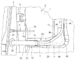
図1はドア用配線装置10が車体2及びドア6に組付けられた状態を示す説明図であり、図2はドア用配線装置10の車体2への取付部分を示す概略分解斜視図であり、図3及び図4はドア6の開閉に伴うドア用配線装置10の動作を示す説明図である。なお、図3はドア6が開いた状態を示し、図4はドア6が閉じた状態を示している。   FIG. 1 is an explanatory view showing a state in which the door wiring device 10 is assembled to the vehicle body 2 and the door 6, and FIG. 2 is a schematic exploded perspective view showing a mounting portion of the door wiring device 10 to the vehicle body 2. 3 and 4 are explanatory views showing the operation of the door wiring device 10 accompanying opening and closing of the door 6. 3 shows a state in which the door 6 is opened, and FIG. 4 shows a state in which the door 6 is closed.

<ドア用配線装置の適用対象例>
まず、ドア用配線装置10の適用対象例について説明する。
<Application examples of door wiring devices>
First, an application target example of the door wiring device 10 will be described.

このドア用配線装置10は、車体2とドア6との間に配設され、それらの間にワイヤーハーネスWHを配索するための装置として構成されている。   The door wiring device 10 is disposed between the vehicle body 2 and the door 6 and is configured as a device for routing the wire harness WH between them.

ここで、ワイヤーハーネスWHは、複数の電線を束ねることによって構成されており、車体2及びドア6に組付けられた状態で、車体側の電源、電子制御ユニット、スイッチ等の電気機器とドア6に搭載されるスイッチ、パワーウインドウモータ、ドアロックモータ、ミラーモータ及びスピーカー等の電気機器とを電気的に接続する。ワイヤーハーネスWHのうち車体2からドア6に架け渡される部分は、複数の電線が1本に束ねられている。また、ワイヤーハーネスWHの端部は、接続先となる電気機器の配置に合わせて適宜分岐されていてもよい。   Here, the wire harness WH is configured by bundling a plurality of electric wires, and in the state assembled to the vehicle body 2 and the door 6, an electric device such as a power source on the vehicle body side, an electronic control unit, a switch, and the door 6. Are electrically connected to electrical devices such as switches, power window motors, door lock motors, mirror motors and speakers. In the portion of the wire harness WH that extends from the vehicle body 2 to the door 6, a plurality of electric wires are bundled into one. Moreover, the edge part of the wire harness WH may be appropriately branched according to arrangement | positioning of the electric equipment used as a connection destination.

ドア6は、車体2に形成されている乗降口を開閉可能なように、車体2に対してドアヒンジ5(一般的に一対のドアヒンジ5を有するが、図1では一方のみ表示)により連結されている。なお、車体2とは、金属部材で形成されたフレーム部分を言うものとする。ここでは、ドア6は、フロントサイドドアであり、説明の便宜上、鉛直方向に沿った軸(ドアヒンジ5の回転軸)周りに姿勢変更するように車体2に対して連結されているものとする。   The door 6 is connected to the vehicle body 2 by door hinges 5 (generally having a pair of door hinges 5, but only one is shown in FIG. 1) so that the entrance / exit formed in the vehicle body 2 can be opened and closed. Yes. The vehicle body 2 refers to a frame portion formed of a metal member. Here, the door 6 is a front side door, and for convenience of explanation, it is assumed that the door 6 is connected to the vehicle body 2 so as to change its posture around an axis along the vertical direction (the rotation axis of the door hinge 5).

なお、上記車体2及びドア6には、ドア6を所定の開度(全開姿勢、半開姿勢等)で維持するための開度規制部3(ドアチェックリンクとも言う)が設けられている。より具体的には、開度規制部3は、アーム部3aとケース部3bとを備えている。アーム部3aは、一端部(以下、車体側連結部)が車体2に対して相対回転可能に連結され、長手方向複数位置に他の部分より肉薄(車体の上下方向に薄肉)な部分が形成された棒状に形成されている。なお、図1では、アーム部3aの厚薄は省略して示している。ケース部3bは、アーム部3aを挿通可能な貫通孔を有する筐状に形成され、その内部にアーム部3aを挟むように押圧付勢される図示省略の挟持部を有している。すなわち、ケース部3bは、挿通されるアーム部3aに対して、挟持部が薄肉部を挟む位置に留まり易くなっている。このケース部3bは、ドア6に対して固定され、開度規制部3のドア側連結部を担っている。   The vehicle body 2 and the door 6 are provided with an opening degree restricting section 3 (also referred to as a door check link) for maintaining the door 6 at a predetermined opening degree (full open attitude, half open attitude, etc.). More specifically, the opening degree restriction part 3 includes an arm part 3a and a case part 3b. One end of the arm portion 3a (hereinafter referred to as a vehicle body side connecting portion) is connected so as to be relatively rotatable with respect to the vehicle body 2, and a portion thinner than other portions (thin in the vertical direction of the vehicle body) is formed at a plurality of positions in the longitudinal direction. It is formed in a bar shape. In FIG. 1, the thickness of the arm portion 3a is omitted. The case portion 3b is formed in a casing shape having a through-hole through which the arm portion 3a can be inserted, and has a not-shown clamping portion that is pressed and urged so as to sandwich the arm portion 3a. That is, the case portion 3b is likely to stay at a position where the sandwiching portion sandwiches the thin portion with respect to the inserted arm portion 3a. The case portion 3 b is fixed to the door 6 and serves as a door side connecting portion of the opening degree restricting portion 3.

そして、ドア6の開閉動作に連動して、アーム部3aがケース部3bに対して相対挿通移動される。ケース部3bの挟持部がアーム部3aの薄肉部を挟む位置にある状態では、厚肉部を乗り越えられるような外力が加えられない限り、ドア6の姿勢が維持される。一般的に、アーム部3aの薄肉部の位置は、ドア6の半開姿勢及び全開姿勢で姿勢維持可能なように設定されている。なお、アーム部3aは、ドア6の閉動作に伴ってドア6内に進入し、開動作に伴ってドア6内から退出する。   Then, in conjunction with the opening / closing operation of the door 6, the arm portion 3a is relatively inserted and moved with respect to the case portion 3b. In a state where the holding part of the case part 3b is in a position to hold the thin part of the arm part 3a, the posture of the door 6 is maintained unless an external force that can get over the thick part is applied. Generally, the position of the thin portion of the arm portion 3a is set so that the posture of the door 6 can be maintained in the half-open posture and the fully-open posture. The arm portion 3a enters the door 6 with the closing operation of the door 6, and retreats from the door 6 with the opening operation.

この開度規制部3は、一般的に、上下方向において一対のドアヒンジ5の間の位置、すなわち、ドア6の中間部分(ウインドウ部分を除く)に設けられる。   The opening degree restricting portion 3 is generally provided at a position between the pair of door hinges 5 in the vertical direction, that is, at an intermediate portion of the door 6 (excluding the window portion).

また、ドア6には、その周縁部に沿って防水用のウェザーストリップ6wが設けられている(図3、図4参照)。このウェザーストリップ6wは、ドア6を閉めた状態で、車体2の乗降口の開口縁部に密着して、車室内外において水密状態を保持可能なゴム等で形成された弾性部材である。そして、本配線装置10は、ウェザーストリップ6wより車室内側にワイヤーハーネスWHを配索できる構成となっている。   Moreover, the weather strip 6w for waterproofing is provided in the door 6 along the peripheral part (refer FIG. 3, FIG. 4). The weather strip 6w is an elastic member formed of rubber or the like that can be in close contact with the opening edge of the entrance / exit of the vehicle body 2 and keep a watertight state inside and outside the vehicle interior with the door 6 closed. And this wiring apparatus 10 becomes a structure which can wire the wire harness WH to the vehicle interior side from the weather strip 6w.

ドア6は、ドアインナーパネル7及びその外側に設けられる外装部材としてのドアアウターパネルと、ドアインナーパネル7の内側に取り付けられる内装部材としてのトリム8とを有している(図3、図4参照)。一般的には、ドアインナーパネル7及びドアアウターパネルは、金属材料で形成され、トリム8は、合成樹脂材料等で形成される。また、ドア6は、その前端部から内部にワイヤーハーネスWHを挿通可能に構成されている。ここでは、ドアインナーパネル7の凹部7hの前方側開口部を通じてドアインナーパネル7とトリム8との間にワイヤーハーネスWHを配索可能になっている(図1参照)。この凹部7hは、後述するプロテクタPを収容する凹状部分であり、ドアインナーパネル7の車室内側で開口すると共に、前記前方側開口部を有している。   The door 6 includes a door inner panel 7, a door outer panel as an exterior member provided outside the door, and a trim 8 as an interior member attached to the inside of the door inner panel 7 (FIGS. 3 and 4). reference). In general, the door inner panel 7 and the door outer panel are formed of a metal material, and the trim 8 is formed of a synthetic resin material or the like. Moreover, the door 6 is comprised so that the wire harness WH can be inserted in the inside from the front-end part. Here, the wire harness WH can be routed between the door inner panel 7 and the trim 8 through the front opening of the recess 7h of the door inner panel 7 (see FIG. 1). The concave portion 7h is a concave portion that accommodates a protector P, which will be described later. The concave portion 7h opens on the vehicle interior side of the door inner panel 7 and has the front opening.

また、車体2には、車体2内にワイヤーハーネスWHを挿通するための孔部2hが形成されている。この孔部2hは、乗降口の開口縁部のうち、凹部7hの前方側開口部に対してドア6の閉姿勢で車体2の前後方向に対向する部分に形成されている。なお、凹部7hの前方側開口部及び孔部2hは、ドア6を閉めた状態では、車体2の内装部材及びドア6のトリム8等により隠れるようになっている。   The vehicle body 2 is formed with a hole 2h for inserting the wire harness WH into the vehicle body 2. The hole 2h is formed in a portion of the opening edge of the entrance / exit that is opposed to the front opening of the recess 7h in the front-rear direction of the vehicle body 2 with the door 6 closed. The front opening and the hole 2h of the recess 7h are hidden by the interior member of the vehicle body 2, the trim 8 of the door 6 and the like when the door 6 is closed.

また、ここでは、ワイヤーハーネスWHが車体2とドア6との間でウェザーストリップ6wより車室内側に配索されるため、凹部7hの前方側開口部及び孔部2hは、当該ウェザーストリップ6wより車室内側に形成されている(図3、図4参照)。   Here, since the wire harness WH is routed between the vehicle body 2 and the door 6 from the weather strip 6w to the vehicle interior side, the front opening and the hole 2h of the recess 7h are formed from the weather strip 6w. It is formed on the vehicle interior side (see FIGS. 3 and 4).

<ドア用配線装置の全体構成>
ドア用配線装置10の全体構成について説明する。ドア用配線装置10は、上記ワイヤーハーネスWHと、コルゲートチューブ20と、プロテクタPとを備えている。
<Overall configuration of door wiring device>
The overall configuration of the door wiring device 10 will be described. The door wiring device 10 includes the wire harness WH, the corrugated tube 20, and the protector P.

コルゲートチューブ20は、ワイヤーハーネスWHのうち車体2からドア6に架け渡される部分を囲うように配設されている。このコルゲートチューブ20は、ワイヤーハーネスWHを、外部から保護すると共に、車体2とドア6との間での垂れ下がり等を抑制する機能を果す。   The corrugated tube 20 is disposed so as to surround a portion of the wire harness WH that extends from the vehicle body 2 to the door 6. The corrugated tube 20 functions to protect the wire harness WH from the outside and to suppress drooping between the vehicle body 2 and the door 6.

すなわち、コルゲートチューブ20は、合成樹脂又は合成ゴム等のエラストマーを、押出成型すると共にブロー成型或いはバキューム成型することにより、筒状に形成されている。そして、コルゲートチューブ20内に、ワイヤーハーネスWHが挿通されることで、当該ワイヤーハーネスWHを保護する。   That is, the corrugated tube 20 is formed in a cylindrical shape by extrusion molding and blow molding or vacuum molding an elastomer such as synthetic resin or synthetic rubber. Then, the wire harness WH is inserted into the corrugated tube 20 to protect the wire harness WH.

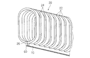
また、コルゲートチューブ20は、環状凸部22と環状凹部24とが軸方向に沿って交互に連続的に形成された構成されている。そして、コルゲートチューブ20に対して外力が加えられると、主として環状凸部22と環状凹部24との境界部分が容易に弾性変形することで、コルゲートチューブ20が全体として容易に曲るようになっている。   Further, the corrugated tube 20 is configured such that the annular convex portions 22 and the annular concave portions 24 are alternately and continuously formed along the axial direction. When an external force is applied to the corrugated tube 20, the boundary portion between the annular convex portion 22 and the annular concave portion 24 is easily elastically deformed, so that the corrugated tube 20 is easily bent as a whole. Yes.

また、コルゲートチューブ20は、扁平な筒状に形成されている。コルゲートチューブ20を扁平な筒状に形成するためには、コルゲートチューブ20の断面視形状を、楕円形或は角を丸められた長方形等に形成するとよい。ここでは、コルゲートチューブ20の断面視形状を、一対の半円弧状形状の両端部を直線部分で連結した形状に形成している。このようにコルゲートチューブ20を扁平な筒状に形成すると、コルゲートチューブ20は、その短径方向では比較的容易に曲げ変形できる一方、その長径方向では比較的曲げ変形し難くなる。そこで、コルゲートチューブ20の短径方向を水平面に沿わせると共に、コルゲートチューブ20の長径方向を、鉛直方向に沿った軸(ドアヒンジ5の回転軸)に沿わせるようにして、コルゲートチューブ20を車体2とドア6との間に配設する。これにより、コルゲートチューブ20は、水平面内において、ドア6の開閉動作に追随して車体2とドア6との間で曲がることができ、また、車体2とドア6との間で垂れ下がりを抑制してワイヤーハーネスWHを支持できる。   The corrugated tube 20 is formed in a flat cylindrical shape. In order to form the corrugated tube 20 in a flat cylindrical shape, the cross-sectional view shape of the corrugated tube 20 may be formed in an elliptical shape or a rectangular shape with rounded corners. Here, the cross-sectional view shape of the corrugated tube 20 is formed in a shape in which both ends of a pair of semicircular arc shapes are connected by a linear portion. When the corrugated tube 20 is formed in a flat cylindrical shape in this way, the corrugated tube 20 can be bent and deformed relatively easily in the minor axis direction, but becomes relatively difficult to bend and deformed in the major axis direction. Therefore, the corrugated tube 20 is mounted on the vehicle body 2 so that the short diameter direction of the corrugated tube 20 is along the horizontal plane and the long diameter direction of the corrugated tube 20 is along the axis (rotation axis of the door hinge 5) along the vertical direction. And the door 6. As a result, the corrugated tube 20 can bend between the vehicle body 2 and the door 6 following the opening and closing operation of the door 6 in a horizontal plane, and suppresses drooping between the vehicle body 2 and the door 6. Can support the wire harness WH.

また、コルゲートチューブ20には、その軸方向に沿って1本のスリット26が形成されている(図2参照)。そして、コルゲートチューブ20を当該スリット26で開くことにより、コルゲートチューブ20内にワイヤーハーネスWHを容易に配設することができるようになっている。なお、ワイヤーハーネスWH自体も扁平な形状に束ねられ、コルゲートチューブ20がワイヤーハーネスWHの外部形状に対応する扁平な形状に形成されていてもよい。   The corrugated tube 20 is formed with one slit 26 along its axial direction (see FIG. 2). Then, by opening the corrugated tube 20 with the slit 26, the wire harness WH can be easily disposed in the corrugated tube 20. The wire harness WH itself may be bundled in a flat shape, and the corrugated tube 20 may be formed in a flat shape corresponding to the external shape of the wire harness WH.

また、コルゲートチューブ20のうちスリット26を挟む一対の縁部のそれぞれにフランジ部60、70が形成されている。このフランジ部60、70については、後でさらに説明する。   In addition, flange portions 60 and 70 are formed on each of a pair of edge portions sandwiching the slit 26 in the corrugated tube 20. The flange portions 60 and 70 will be further described later.

また、コルゲートチューブ20の一端部は、ワイヤーハーネスWHのうち車体2内に配索される部分に対してテープT巻き等されて固定されている。また、コルゲートチューブ20の一端部には、車体2に取り付けられる取付部材30が固定されている。また、コルゲートチューブ20の他端部は、ワイヤーハーネスWHのうちドア6内(ここでは後述する案内部50内)に配索される部分にテープT巻き等されて固定され、当該ワイヤーハーネスWHと共にドア6内に進退移動可能とされている。   Further, one end portion of the corrugated tube 20 is fixed by being wound with a tape T around a portion of the wire harness WH that is routed in the vehicle body 2. An attachment member 30 attached to the vehicle body 2 is fixed to one end portion of the corrugated tube 20. Further, the other end portion of the corrugated tube 20 is fixed by being wound with a tape T or the like on a portion of the wire harness WH that is routed in the door 6 (in the guide portion 50 described later), together with the wire harness WH. It can be moved forward and backward in the door 6.

取付部材30(エッジプロテクタとも言う)は、コルゲートチューブ20の一方の端部寄りの一部分を車体2に対して固定可能に構成されている(図2参照)。この取付部材30は、コルゲートチューブ20のうち一方の端部寄りの一部分に固定され、車体2のうち一対のドアヒンジ5間の部位に取り付けられている(図1、図3、図4参照)。より具体的には、取付部材30は、車体2に形成されている孔部2hに対して押し付けることにより取り付け可能に構成されている。この取付部材30は、挿入部34と、押え部36と、凹凸嵌合部38とを有している。   The attachment member 30 (also referred to as an edge protector) is configured to be able to fix a part near one end of the corrugated tube 20 to the vehicle body 2 (see FIG. 2). The attachment member 30 is fixed to a part of the corrugated tube 20 near one end, and is attached to a portion of the vehicle body 2 between the pair of door hinges 5 (see FIGS. 1, 3, and 4). More specifically, the attachment member 30 is configured to be attachable by being pressed against a hole 2 h formed in the vehicle body 2. The attachment member 30 has an insertion part 34, a pressing part 36, and a concave / convex fitting part 38.

挿入部34は、車体2の孔部2h内に挿入可能、且つ、内側にコルゲートチューブ20を配設可能な筒状に形成されている。ここでは、挿入部34は、孔部2hに対して車体2の前方(以下、挿入方向S)に向けて挿入される。挿入部34の先端側部分には、挿入部34を孔部2h内に挿入した状態で孔部2hの周縁部に対して係止可能な係止部35が設けられている。この係止部35は、挿入部34の周方向複数位置(ここでは等間隔に4箇所)から外周側に突出するように形成され、それぞれ、孔部2hの周縁部に対して挿入方向S前方側から接触可能な係止面を有している。より具体的には、係止部35は、挿入部34の先端側から基端側に向けて徐々に突出寸法が大きくなるように形成されている。そして、各係止部35は、挿入部34が孔部2hに挿入される際に、挿入部34又は係止部35自身が挿入部34の内周側に弾性変形し、孔部2hを乗り越えた位置で外周側に弾性復帰して孔部2hの周縁部に係止する。   The insertion portion 34 is formed in a cylindrical shape that can be inserted into the hole 2 h of the vehicle body 2 and in which the corrugated tube 20 can be disposed. Here, the insertion part 34 is inserted toward the front of the vehicle body 2 (hereinafter, the insertion direction S) with respect to the hole 2h. The distal end portion of the insertion portion 34 is provided with a locking portion 35 that can be locked to the peripheral edge portion of the hole portion 2h in a state where the insertion portion 34 is inserted into the hole portion 2h. The locking portions 35 are formed so as to protrude from the circumferential positions of the insertion portion 34 in the circumferential direction (four locations at equal intervals) to the outer peripheral side, and are respectively forward in the insertion direction S with respect to the peripheral portion of the hole 2h. It has a locking surface that can be contacted from the side. More specifically, the locking portion 35 is formed so that the protruding dimension gradually increases from the distal end side to the proximal end side of the insertion portion 34. When each of the locking portions 35 is inserted into the hole 2h, the insertion portion 34 or the locking portion 35 itself is elastically deformed toward the inner peripheral side of the insertion portion 34, and gets over the hole 2h. It is elastically returned to the outer peripheral side at the raised position and locked to the peripheral edge of the hole 2h.

押え部36は、挿入部34の基端部に連続して設けられ、その外周側に張り出す鍔状に形成されている。この押え部36は、孔部2hの周縁部に対して、挿入方向S後方側から面接触可能である。すなわち、押え部36の外周形状は、孔部2hより大きく形成されている。   The presser portion 36 is provided continuously with the proximal end portion of the insertion portion 34 and is formed in a hook shape projecting to the outer peripheral side thereof. The pressing portion 36 can come into surface contact with the peripheral portion of the hole 2h from the rear side in the insertion direction S. That is, the outer peripheral shape of the pressing portion 36 is formed larger than the hole portion 2h.

そして、挿入部34が孔部2hに挿入されると、係止部35が孔部2hの周縁部に対して挿入方向S前方側から係止すると共に、押え部36が孔部2hの周縁部に対して挿入方向S後方側から面接触する。これにより、孔部2hの周縁部が係止部35と押え部36とで挟まれて、取付部材30は車体2に対して固定される。   When the insertion part 34 is inserted into the hole 2h, the locking part 35 is locked from the front side in the insertion direction S with respect to the peripheral part of the hole 2h, and the presser part 36 is the peripheral part of the hole 2h. Is in surface contact from the rear side in the insertion direction S. Thus, the peripheral edge of the hole 2 h is sandwiched between the locking portion 35 and the pressing portion 36, and the attachment member 30 is fixed to the vehicle body 2.

凹凸嵌合部38は、挿入部34(及び押え部36)内に配設されるコルゲートチューブ20に対して、その延在方向に相対移動不能に位置決めする部分である。ここでは、凹凸嵌合部38は、コルゲートチューブ20の外周の凹凸形状に応じた凹凸形状に形成されている。より具体的には、凹凸嵌合部38は、挿入部34の内周部に、その周方向に沿った凸条が形成された構成とされている。各凸条は、コルゲートチューブ20の環状凸部22間の環状凹部24間に嵌め込み可能な幅寸法及び高さ寸法に形成されている。また、凸条は、挿入方向Sにおいて、コルゲートチューブ20の環状凹部24に対応する間隔で複数設けられている。   The concave / convex fitting portion 38 is a portion that is positioned so as not to move relative to the corrugated tube 20 disposed in the insertion portion 34 (and the pressing portion 36) in the extending direction thereof. Here, the concave / convex fitting portion 38 is formed in a concave / convex shape corresponding to the concave / convex shape on the outer periphery of the corrugated tube 20. More specifically, the concave-convex fitting portion 38 has a configuration in which a protrusion along the circumferential direction is formed on the inner peripheral portion of the insertion portion 34. Each protrusion is formed in a width dimension and a height dimension that can be fitted between the annular recesses 24 between the annular protrusions 22 of the corrugated tube 20. Further, a plurality of ridges are provided in the insertion direction S at intervals corresponding to the annular recess 24 of the corrugated tube 20.

また、取付部材30は、環状部材が2分割された部材を合体させることにより構成される。ここでは、取付部材30は、対向片の長さが異なるJ字部材(U字状部材であってもよい)を合体させることにより構成される。また、一対の略J字部材の各突き合わせ部分に、互いに嵌合可能な凹凸部分が形成され、これらの凹凸部分が互いに嵌合することにより一対の略J字部材が合体される。すなわち、一対の略J字部材によりコルゲートチューブ20を挟み込むことにより、凹凸嵌合部38がコルゲートチューブ20の外周部に対して嵌合し、取付部材30は、コルゲートチューブ20に対して延在方向に相対移動不能に取り付けられる。なお、取付部材30は、一対の略J字部材が、合体された状態において、分離不能に係合する形状を有していることが好ましいが、孔部2hに嵌合されることにより合体状態を維持されるものでもよい。また、取付部材30は、一対の略J字部材が、開閉可能なようにヒンジにより一端部で連結されていてもよい。   Moreover, the attachment member 30 is comprised by uniting the member into which the annular member was divided into two. Here, the mounting member 30 is configured by combining J-shaped members (which may be U-shaped members) having different lengths of the facing pieces. Moreover, the uneven | corrugated | grooved part which can mutually fit is formed in each butt | matching part of a pair of substantially J-shaped member, and a pair of substantially J-shaped member is united | combined when these uneven | corrugated parts mutually fit. That is, the corrugated tube 20 is sandwiched between a pair of substantially J-shaped members, whereby the concave / convex fitting portion 38 is fitted to the outer peripheral portion of the corrugated tube 20, and the mounting member 30 extends in the extending direction with respect to the corrugated tube 20. It is attached so that relative movement is impossible. Note that the mounting member 30 preferably has a shape that allows a pair of substantially J-shaped members to be engaged in a non-separable state in a combined state, but the combined state by being fitted into the hole 2h. May be maintained. Further, the attachment member 30 may be connected at one end by a hinge so that a pair of substantially J-shaped members can be opened and closed.

もっとも、取付部材30は、上記形状に限られるものではない。例えば、ワイヤーハーネスWHを位置決めする部分が、押え部36の基端部から挿入方向S後方に向けて突出する扁平な細長矩形状に形成されていてもよい。すなわち、挿入部34(及び押え部36)内に配設したコルゲートチューブ20を、当該位置決め部に対して、テープ巻き又はタイバンドで締め付ける等して固定することにより、取付部材30に対して挿入方向Sに位置決めすることができる。なお、タイバンドとは、環状体の周方向寸法を調節し保持可能な部材をいう。このような位置決め部を採用する場合、取付部材は、全体として射出成型により一体に形成されてもよい。   But the attachment member 30 is not restricted to the said shape. For example, the portion for positioning the wire harness WH may be formed in a flat and narrow rectangular shape that protrudes from the proximal end portion of the presser portion 36 toward the rear in the insertion direction S. That is, the corrugated tube 20 disposed in the insertion portion 34 (and the presser portion 36) is inserted into the attachment member 30 by fixing the corrugated tube 20 to the positioning portion by, for example, tape winding or fastening with a tie band. It can be positioned in direction S. A tie band refers to a member that can adjust and maintain the circumferential dimension of an annular body. When employing such a positioning portion, the attachment member may be integrally formed by injection molding as a whole.

また、取付部材30は、車体2に取り付け可能で且つコルゲートチューブ20を固定可能であればよく、上記のような樹脂成形品に限られず、合成ゴム等のエラストマーで成形されたグロメットであってもよい。また、この取付部材30は、必ずしも必須ではなく、省略されてもよい。   The attachment member 30 only needs to be attachable to the vehicle body 2 and fix the corrugated tube 20, and is not limited to the resin molded product as described above, and may be a grommet formed of an elastomer such as synthetic rubber. Good. Moreover, this attachment member 30 is not necessarily essential and may be omitted.

プロテクタPは、ドア6内で、ワイヤーハーネスWHの経路規制を行いつつ、当該ワイヤーハーネスWHの余長を吸収するための部材であり、案内部50と収容部40とを有している(図1参照)。   The protector P is a member for absorbing the surplus length of the wire harness WH while restricting the path of the wire harness WH within the door 6, and includes a guide portion 50 and a storage portion 40 (see FIG. 1).

案内部50は、ドア6のうち一対のドアヒンジ5の間の部位からドア6の内部に亘る領域に配置され、コルゲートチューブ20のうち他方の端部を含む一部分のドア6内における変位経路を案内する筒状又は溝状に形成されている。また、収容部40は、ドア6内において案内部50に連なって設けられている。ここでは、収容部40と案内部50とは、樹脂による一体形成部品として構成されているが、必ずしもその必要はなく、別々の部材として形成された後、合体される構成であってもよい。そして、コルゲートチューブ20の他方の端部から延び出たワイヤーハーネスWHを、該ワイヤーハーネスWHが迂回可能な余裕空間を有する状態、即ち、余長吸収可能な状態で収容する部分である。   The guide portion 50 is disposed in a region extending from the portion between the pair of door hinges 5 to the inside of the door 6 in the door 6, and guides a displacement path in a part of the door 6 including the other end portion of the corrugated tube 20. It is formed in a cylindrical shape or a groove shape. In addition, the accommodating portion 40 is provided in the door 6 so as to be continuous with the guide portion 50. Here, although the accommodating part 40 and the guide part 50 are comprised as an integrally formed component by resin, it is not necessarily required, and the structure united after forming as a separate member may be sufficient. And it is a part which accommodates the wire harness WH extended from the other edge part of the corrugated tube 20 in the state which has the allowance space which this wire harness WH can bypass, ie, the state which can absorb extra length.

案内部50の一端部にはコルゲートチューブ20の他端側部分を挿入可能な案内口52が設けられ、案内部50の他端部は収容部40の一端部と連続している。また、収容部40は、連通する案内部50内に挿入されるコルゲートチューブ20の他端部から延出されるワイヤーハーネスWHを余長吸収可能に収容可能な収容空間を有している。すなわち、収容空間は、ワイヤーハーネスWHを迂回させるための余裕空間を含む空間である。この収容部40は、案内部50を通じて収容空間内に進退可能に挿入されるワイヤーハーネスWHを、ドア6内に引き出し可能な引出口44を有している。つまり、プロテクタPは、案内口52を通じて案内部50内に挿入されるコルゲートチューブ20を収容部40に向けて案内し、そのコルゲートチューブ20の他端部から延出されるワイヤーハーネスWHを、収容部40の収容空間内で余長吸収可能に収容して引出口44を通じてその外方すなわちドア6内に延出させる部材である。そして、ワイヤーハーネスWHは、ドア6内において、プロテクタPにより周辺部材から保護される。図1では、案内口52と引出口44とが略直交する方向に開口し、全体として正面視略L字形状に形成されているプロテクタPを示している。ここで、プロテクタP(ドア用配線装置10)の正面とは、案内口52の開口方向(案内部50の案内方向)と引出口44の開口方向とに平行な面である。また、プロテクタPをドア6に取り付けた状態で説明すると、車室内外を結ぶ方向に直交する面が正面である。   A guide port 52 into which the other end portion of the corrugated tube 20 can be inserted is provided at one end portion of the guide portion 50, and the other end portion of the guide portion 50 is continuous with one end portion of the accommodating portion 40. Moreover, the accommodating part 40 has the accommodating space which can accommodate the wire harness WH extended from the other end part of the corrugated tube 20 inserted in the guide part 50 connected in a reversible manner. That is, the accommodation space is a space including a margin space for bypassing the wire harness WH. The accommodating portion 40 has a pull-out port 44 through which the wire harness WH that is inserted into the accommodating space through the guide portion 50 so as to be able to advance and retreat can be drawn into the door 6. In other words, the protector P guides the corrugated tube 20 inserted into the guide portion 50 through the guide port 52 toward the housing portion 40, and the wire harness WH extended from the other end of the corrugated tube 20 is guided to the housing portion. It is a member that is accommodated in the accommodating space 40 so as to be able to absorb the extra length and extends outwardly, that is, into the door 6 through the outlet 44. The wire harness WH is protected from the peripheral members by the protector P in the door 6. FIG. 1 shows a protector P in which the guide port 52 and the outlet 44 are opened in a direction substantially orthogonal to each other and formed in a substantially L shape in front view. Here, the front surface of the protector P (the door wiring device 10) is a surface parallel to the opening direction of the guide port 52 (guide direction of the guide portion 50) and the opening direction of the outlet 44. Moreover, if it demonstrates in the state which attached the protector P to the door 6, the surface orthogonal to the direction which connects the vehicle interior and exterior is a front.

案内部50及び収容部40の各構成について着目してより詳細に説明する。   The configuration of the guide unit 50 and the storage unit 40 will be described in detail with attention paid to each component.

案内部50は、コルゲートチューブ20をその延在方向に進退移動可能に配設可能な内部空間を有する筒状に形成されている(図1、図3,図4参照)。ここでは、案内部50は、コルゲートチューブ20の断面形状に対応した断面視略長方形の筒状である。換言すると、案内部50は、コルゲートチューブ20の断面形状に外接する長方形と同じ又は大きい(ここでは、僅かに大きい)長方形形状の断面の筒状に形成されている。そして、案内部50は、挿入されるコルゲートチューブ20の外周部に当接することにより、当該コルゲートチューブ20を案内方向に直交する方向(主として車室内外方向)において位置規制する。これにより、コルゲートチューブ20の他方の端部を含む部分は、案内口52と収容部40とを結ぶ経路に沿って移動可能に案内される。もっとも、案内部50は、コルゲートチューブ20を挿通案内可能であればよく、溝状、断面視略楕円形、円形或いは長方形以外の多角形等の筒状に形成されていてもよい。   The guide portion 50 is formed in a cylindrical shape having an internal space in which the corrugated tube 20 can be disposed so as to be able to advance and retreat in the extending direction (see FIGS. 1, 3, and 4). Here, the guide portion 50 has a substantially rectangular tube shape in cross-sectional view corresponding to the cross-sectional shape of the corrugated tube 20. In other words, the guide portion 50 is formed in a cylindrical shape having a rectangular cross section that is the same as or larger than the rectangle circumscribing the cross sectional shape of the corrugated tube 20 (here, slightly larger). And the guide part 50 abuts on the outer peripheral part of the corrugated tube 20 to be inserted, thereby restricting the position of the corrugated tube 20 in a direction orthogonal to the guiding direction (mainly in the interior and exterior direction). Thereby, the part including the other end part of the corrugated tube 20 is guided so as to be movable along a path connecting the guide port 52 and the accommodating part 40. But the guide part 50 should just be able to insert and guide the corrugated tube 20, and may be formed in cylindrical shapes, such as a groove shape, a cross-sectional view substantially elliptical shape, circular, or polygons other than a rectangle.

ここで、案内部50とコルゲートチューブ20との関係について説明しておく。コルゲートチューブ20は、一端側部分が取付部材30を介して車体2に固定された状態で、ドア6の開状態において、少なくとも他端部を含む一部分が案内部50内に挿入される程度に長い延在寸法に設定されている。一方、案内部50は、ドア6が開閉動作される際に、ドア6内で進退されるコルゲートチューブ20の他端側部分を主として車室内外方向に位置規制できればよく、ここでは、ドア6の閉状態において、コルゲートチューブ20の他端部を収容部40内に突出させる程度の延在寸法に設定されている。もっとも、案内部50は、上記寸法より長く、ドア6の閉状態でコルゲートチューブ20の他端部まで収容可能に設定されていてもよい。   Here, the relationship between the guide part 50 and the corrugated tube 20 is demonstrated. The corrugated tube 20 is long enough to insert at least a portion including the other end portion into the guide portion 50 when the door 6 is in an open state with the one end side portion fixed to the vehicle body 2 via the mounting member 30. The extension dimension is set. On the other hand, the guide unit 50 only needs to be able to regulate the position of the other end portion of the corrugated tube 20 that is advanced and retracted in the door 6 mainly when the door 6 is opened and closed. In the closed state, the extension dimension is set such that the other end portion of the corrugated tube 20 protrudes into the accommodating portion 40. But the guide part 50 is longer than the said dimension, and may be set so that accommodation to the other end part of the corrugated tube 20 in the closed state of the door 6 is possible.

また、案内部50の一端部に形成されている案内口52は、外周側に拡開するように形成されていてもよい(図1、図3、図4参照)。ここでは、案内部50は、その延在方向に略直交する全方向に拡がる形状を採用している。この案内口52は、一端部に向けて徐々に拡がるように形成されている。   Moreover, the guide port 52 formed in the one end part of the guide part 50 may be formed so that it may expand on an outer peripheral side (refer FIG.1, FIG.3, FIG.4). Here, the guide portion 50 adopts a shape that expands in all directions substantially orthogonal to the extending direction. The guide port 52 is formed so as to gradually expand toward one end.

収容部40は、コルゲートチューブ20の他端部から延出されるワイヤーハーネスWHを、第1経路R1と、当該第1経路R1に対して中間部が離間するように膨らんだ第2経路R2との間で曲げて余長吸収可能に収容可能に形成されている(図1参照)。   The accommodating portion 40 includes a wire harness WH extending from the other end portion of the corrugated tube 20 and a first route R1 and a second route R2 that swells so that an intermediate portion is separated from the first route R1. It is formed so that it can be accommodated so as to be able to absorb the extra length by bending between them (see FIG. 1).

この収容部40は、正面視において、収容空間を挟んで対向する第1壁部41と第2壁部42とを有している。収容空間内に収容されるワイヤーハーネスWHは、第1経路R1を通る際に第1壁部41に近接し、第2経路R2を通る際に第2壁部42に近接して配設される。すなわち、ワイヤーハーネスWHが第1経路R1を通る状態で、該ワイヤーハーネスWHの第2壁部42側に余裕空間が存在する。この第1壁部41及び第2壁部42は、各一端部が案内部50の他端部に連続し、各他端部が引出口44の対向する壁部を形成している。より具体的には、第1壁部41は、正面視略L字形状のプロテクタPの内周側で、案内部50の他端部と収容部40の引出口44とを結ぶように延在している。また、第2壁部42は、第1壁部41に対してワイヤーハーネスWHを曲げ変形可能な間隔をあけて、正面視略L字形状のプロテクタPの外周側で、案内部50の他端部と引出口44とを結ぶように延在している。   The housing portion 40 includes a first wall portion 41 and a second wall portion 42 that face each other with a housing space in between when viewed from the front. The wire harness WH accommodated in the accommodation space is disposed close to the first wall portion 41 when passing through the first route R1 and close to the second wall portion 42 when passing through the second route R2. . That is, in a state where the wire harness WH passes through the first path R1, there is a margin space on the second wall portion 42 side of the wire harness WH. Each of the first wall portion 41 and the second wall portion 42 is continuous with the other end portion of the guide portion 50, and each other end portion forms a wall portion facing the outlet 44. More specifically, the first wall portion 41 extends so as to connect the other end portion of the guide portion 50 and the outlet 44 of the accommodating portion 40 on the inner peripheral side of the protector P that is substantially L-shaped when viewed from the front. is doing. In addition, the second wall portion 42 is spaced from the first wall portion 41 so that the wire harness WH can be bent and deformed, and is on the outer peripheral side of the substantially L-shaped protector P in the front view, and the other end of the guide portion 50. It extends so as to connect the section and the outlet 44.

ドア6の開閉時におけるワイヤーハーネスWH及びコルゲートチューブ20の動作について説明する。   The operation of the wire harness WH and the corrugated tube 20 when the door 6 is opened and closed will be described.

ドア6の開状態では、コルゲートチューブ20の他端部が案内部50のうち一端側の部分に退避して位置し、当該コルゲートチューブ20の他端部から延出されるワイヤーハーネスWHは、第1経路R1を通って収容空間内に収容されている(図1、図3参照)。   In the open state of the door 6, the other end portion of the corrugated tube 20 is retracted and positioned in a portion on one end side of the guide portion 50, and the wire harness WH extending from the other end portion of the corrugated tube 20 is the first It is accommodated in the accommodation space through the route R1 (see FIGS. 1 and 3).

また、ドア6が開姿勢から閉動作されると、コルゲートチューブ20が案内部50内に前進移動し、その他端部から延出されるワイヤーハーネスWHは、収容空間内に押し込まれて第2壁部42に近接するように曲げられる。そして、ドア6が閉姿勢になると、ワイヤーハーネスWHは、第2経路R2を通って収容空間内に収容された状態となる(図1、図4参照)。すなわち、ドア6の開状態に比べ、ワイヤーハーネスWHのうち収容空間内に収容される部分は長くなって余長吸収される。   Further, when the door 6 is closed from the open position, the corrugated tube 20 moves forward into the guide portion 50, and the wire harness WH extended from the other end is pushed into the housing space and the second wall portion. It is bent so as to be close to 42. And if the door 6 will be in a closed position, the wire harness WH will be in the state accommodated in the accommodation space through 2nd path | route R2 (refer FIG. 1, FIG. 4). That is, compared with the open state of the door 6, the part accommodated in accommodation space among the wire harnesses WH becomes long, and extra length is absorbed.

ドアの開動作時には、閉動作時とは逆に、ワイヤーハーネスWHは、収容空間内から案内部50側に引き出されて、その中の部分が第2経路R2から第1経路R1側に経路変更される(図1、図3参照)。   When the door is opened, contrary to the closing operation, the wire harness WH is pulled out from the accommodation space to the guide portion 50 side, and the portion in the wire harness WH is changed from the second route R2 to the first route R1 side. (See FIGS. 1 and 3).

収容部40の説明に戻って、収容部40は、引出口44でワイヤーハーネスWHを固定可能なドア内位置決め部46を有している。ドア内位置決め部46は、引出口44の開口縁部が部分的に延出した形状に形成されている(図1参照)。そして、引出口44を通じて引き出されるワイヤーハーネスWHを、ドア内位置決め部46の内側に当接させた状態で、一緒にテープT巻き又はタイバンドで締付けして固定(ここではテープT巻きして固定)することにより、当該ワイヤーハーネスWHの一部分をドア6内において位置決め固定することができる。これにより、ドア6の開閉動作時に収容部40内に車体2側のワイヤーハーネスWHが進退しても、ドア6内に配索されるワイヤーハーネスWHに対して引張り又は弛みが発生することを抑制して、収容空間内で余長吸収させることができる。   Returning to the description of the accommodating portion 40, the accommodating portion 40 has an in-door positioning portion 46 that can fix the wire harness WH at the outlet 44. The in-door positioning part 46 is formed in a shape in which the opening edge of the outlet 44 partially extends (see FIG. 1). Then, the wire harness WH drawn through the outlet 44 is in contact with the inside of the in-door positioning portion 46 and is fastened together with a tape T or tie band and fixed (here, fixed with a tape T). ), A part of the wire harness WH can be positioned and fixed in the door 6. Thereby, even if the wire harness WH on the vehicle body 2 side advances or retreats in the housing portion 40 during the opening / closing operation of the door 6, it is possible to prevent the wire harness WH routed in the door 6 from being pulled or loosened. Thus, the extra length can be absorbed in the accommodation space.

ワイヤーハーネスWHを収容部40に対して固定する構成は、上記ドア内位置決め部46に限られず、引出口44から壁状に延出するドア内位置決め部にタイバンド挿通用の孔部が複数形成され、タイバンドを孔部に挿通してワイヤーハーネスWHを締付け固定するものであってもよい。   The structure for fixing the wire harness WH to the housing portion 40 is not limited to the in-door positioning portion 46, and a plurality of holes for inserting a tie band are formed in the in-door positioning portion extending in a wall shape from the outlet 44. The wire harness WH may be fastened and fixed by inserting the tie band into the hole.

なお、ワイヤーハーネスWHに加わる負荷を軽減する観点では、収容部40の好ましい形状は以下の通りである。以下、正面視における第1壁部41及び第2壁部42の形状を説明する。すなわち、第1壁部41は、ドア6の開状態において、ワイヤーハーネスWHのうちコルゲートチューブ20の他端部とドア内位置決め部46との中間部分を、当該コルゲートチューブ20の他端部とドア内位置決め部46とを結ぶ方向に平行な経路で収容するように経路規制可能に形成されている。また、第2壁部42は、ワイヤーハーネスWHが、案内部50の案内方向に沿ったライン及びドア内位置決め部46を通って案内方向に直交するライン上を通る経路より大きく曲げられることを規制可能に形成されている。ここでは、第2壁部42は、案内方向に沿った壁部と引出口44の貫通方向に沿った壁部とを湾曲部が接続する形状に形成されている。当該湾曲部は、部分的に案内部50から離間する向きにワイヤーハーネスWHの直径分より小さい寸法だけ膨らむように形成されている。   In addition, from the viewpoint of reducing the load applied to the wire harness WH, the preferable shape of the accommodating portion 40 is as follows. Hereinafter, the shape of the 1st wall part 41 and the 2nd wall part 42 in front view is demonstrated. That is, in the open state of the door 6, the first wall portion 41 has an intermediate portion between the other end portion of the corrugated tube 20 and the in-door positioning portion 46 in the wire harness WH, and the other end portion of the corrugated tube 20 and the door. It is formed so that the path can be regulated so as to be accommodated in a path parallel to the direction connecting the inner positioning portion 46. In addition, the second wall portion 42 restricts the wire harness WH from being bent larger than a path passing through a line along the guide direction of the guide portion 50 and a line perpendicular to the guide direction through the door positioning portion 46. It is made possible. Here, the 2nd wall part 42 is formed in the shape where a curved part connects the wall part along the penetration direction of the wall part along the guide direction, and the outlet 44. As shown in FIG. The curved portion is formed so as to bulge by a size smaller than the diameter of the wire harness WH in a direction partially away from the guide portion 50.

もっとも、収容部40は、ワイヤーハーネスWHを余長吸収可能に収容するものであればよく、上記形状に限られるものではない。例えば、収容空間内に巻軸部を有し、当該巻軸部周りにワイヤーハーネスWHを巻いて収容可能な形状であってもよい。すなわち、収容部内でワイヤーハーネスWHの巻き径が変化することにより、余長吸収する構成である。なお、このようにワイヤーハーネスWHを巻いて余長吸収する構成でもよいが、本実施形態に係る上述した構成を採用すると、ワイヤーハーネスWHを交差させずに余長吸収できるため、収容部40の厚さ寸法を小さくすることができる。   But the accommodating part 40 should just be what accommodates the wire harness WH so that extra length absorption is possible, and is not restricted to the said shape. For example, the shape which has a winding-axis part in accommodation space and can wind and wind the wire harness WH around the said winding-axis part may be sufficient. That is, it is the structure which absorbs surplus length by the winding diameter of the wire harness WH changing within an accommodating part. In addition, although the structure which winds the wire harness WH in this way and absorbs surplus length may be sufficient, when the structure mentioned above which concerns on this embodiment is employ | adopted, surplus length can be absorbed without crossing the wire harness WH, Therefore The thickness dimension can be reduced.

このプロテクタPは、ドア6内すなわちドアインナーパネル7とトリム8との間において、ドアインナーパネル7に形成されている凹部7h内に収容配設される。より具体的には、プロテクタPは、下記の姿勢及び位置でドア6内に配置可能なように、ドアインナーパネル7に対して固定可能に形成されている。   The protector P is accommodated in a recess 7 h formed in the door inner panel 7 in the door 6, that is, between the door inner panel 7 and the trim 8. More specifically, the protector P is formed so as to be fixable to the door inner panel 7 so that it can be disposed in the door 6 in the following posture and position.

プロテクタPは、案内部50が収容部40に対して前方側に位置すると共にドア6の前後方向に沿って延在し、引出口44がドア6の上方を向く姿勢でドア6内に配置されている。また、インナーパネル7の凹部7hは、プロテクタPを、上記姿勢且つ上記位置で、全体的又は部分的に収容可能な収容空間を有する凹形状に形成されている。そして、案内部50の案内口52は、凹部7hのうちドア6の前方の開口部を通じてドア6から外に露出される。   The protector P is disposed in the door 6 such that the guide portion 50 is positioned on the front side with respect to the housing portion 40 and extends along the front-rear direction of the door 6, and the outlet 44 faces the upper side of the door 6. ing. Further, the concave portion 7h of the inner panel 7 is formed in a concave shape having an accommodation space in which the protector P can be accommodated entirely or partially in the posture and the position. And the guide port 52 of the guide part 50 is exposed outside from the door 6 through the opening part ahead of the door 6 among the recessed parts 7h.

上述したように、凹部7hの前側の開口部と車体2に形成されている孔部2hとは、ドア6の閉状態において、車体2の前後方向に対向するように形成されている。そして、取付部材30及びプロテクタPは、ドア6の閉状態において、当該取付部材30と案内部50の案内口52とが車体2の前後方向に対向する位置で車体2に取り付け又はドア6内に配置されている。より具体的には、ドア6の閉状態では、取付部材30の貫通方向(挿入方向S)と案内部50の延在方向とが略直線上に位置する。これにより、取付部材30及び案内部50に挿通されるコルゲートチューブ20及びその内部のワイヤーハーネスWHは、ドア6の閉状態において、略直線状に延在する。   As described above, the opening on the front side of the recess 7 h and the hole 2 h formed in the vehicle body 2 are formed so as to face each other in the front-rear direction of the vehicle body 2 when the door 6 is closed. The attachment member 30 and the protector P are attached to the vehicle body 2 or in the door 6 at a position where the attachment member 30 and the guide port 52 of the guide portion 50 face each other in the front-rear direction of the vehicle body 2 when the door 6 is closed. Has been placed. More specifically, in the closed state of the door 6, the penetrating direction (insertion direction S) of the attachment member 30 and the extending direction of the guide portion 50 are positioned on a substantially straight line. Thereby, the corrugated tube 20 inserted through the attachment member 30 and the guide portion 50 and the wire harness WH inside thereof extend substantially linearly in the closed state of the door 6.

ここでは、プロテクタPは、ドアインナーパネル7の凹部7hの底部に形成される孔部に対して嵌合可能な固定部58を有している。この固定部58は、プロテクタPを凹部7h内に収容する方向に押し付けることにより、孔部に嵌合可能に形成されている。例えば、固定部58としては、プロテクタPの外面から突出する基軸部と、その先端部からその外周側に拡がるように形成され、内周側に弾性変形可能な係止部とを有する構成を採用できる。ここでは、固定部58は、プロテクタPの一方側の外面のうち、案内部50及び収容部40からそれぞれ突出するように2箇所に設けられている。より具体的には、固定部58は、案内部50が収容部40の前方側に位置すると共に引出口44がドア6の上方を向く姿勢のプロテクタPのうち、車室外側の面から当該車室外側に向けて突出している。   Here, the protector P has a fixing portion 58 that can be fitted into a hole formed in the bottom of the recess 7 h of the door inner panel 7. The fixing portion 58 is formed so as to be able to fit into the hole portion by pressing the protector P in the direction in which the protector P is accommodated in the concave portion 7h. For example, the fixed portion 58 has a base shaft portion that protrudes from the outer surface of the protector P, and a locking portion that is formed so as to expand from the tip portion to the outer peripheral side and elastically deformable on the inner peripheral side. it can. Here, the fixing part 58 is provided in two places so that it may protrude from the guide part 50 and the accommodating part 40 among the outer surfaces on one side of the protector P, respectively. More specifically, the fixed portion 58 is provided on the protector P in a posture in which the guide portion 50 is located on the front side of the accommodating portion 40 and the outlet 44 faces the upper side of the door 6. It protrudes toward the outdoor side.

そして、この固定部58を凹部7hに形成された孔部に挿入することにより、係止部が、孔部に当接して内周側に弾性変形し、孔部を越えると外周側に弾性復帰して孔部の周縁部に対して裏側から係止する。このように、上記固定部58によりドアインナーパネル7に対して固定可能なプロテクタPによると、プロテクタPを凹部7h内に配設する方向に近接させることにより、固定部58が凹部7hに形成された孔部に係止するため、容易に固定することが可能である。   Then, by inserting the fixing portion 58 into the hole formed in the concave portion 7h, the locking portion comes into contact with the hole and elastically deforms toward the inner peripheral side, and when it exceeds the hole, elastically returns to the outer peripheral side. And it latches from the back side with respect to the peripheral part of a hole. Thus, according to the protector P that can be fixed to the door inner panel 7 by the fixing portion 58, the fixing portion 58 is formed in the recess 7h by bringing the protector P close to the direction in which the protector P is disposed in the recess 7h. Because it is locked in the hole, it can be easily fixed.

もっとも、プロテクタPをドアインナーパネル7に対して固定するための構成は、上記の姿勢及び位置でドア6内に配設可能であればよく、その他の固定構造が採用されてもよい。例えば、プロテクタPは、ねじ止めによりドアインナーパネル7に対して固定可能な形状であってもよい。   But the structure for fixing the protector P with respect to the door inner panel 7 should just be arrange | positioned in the door 6 with said attitude | position and position, and another fixing structure may be employ | adopted. For example, the protector P may have a shape that can be fixed to the door inner panel 7 by screwing.

上記姿勢及び位置でドア6内に配設されるプロテクタPの引出口44は、ドア6内のうち上側部分に位置する。一般的に、ドア内に搭載されるスイッチ、パワーウインドウモータ、ドアロック及びミラーモータ等の電気機器は、ドア6内の上側部分に設置されることが多い。このため、ドア6内に配索されるワイヤーハーネスWHは、より短い経路で電気機器に対して接続される。   The outlet 44 of the protector P disposed in the door 6 in the posture and position is located in the upper portion of the door 6. Generally, electrical devices such as a switch, a power window motor, a door lock, and a mirror motor mounted in the door are often installed in the upper portion of the door 6. For this reason, the wire harness WH routed in the door 6 is connected to the electrical device through a shorter path.

なお、収容部は、ドア6内におけるワイヤーハーネスWHの経路の短縮化の観点から、引出口(及び収容部全体)を各種電気機器の設置位置(通常後方)に向けて傾斜させて形成されてもよい。   In addition, from the viewpoint of shortening the path of the wire harness WH in the door 6, the accommodating portion is formed by inclining the outlet (and the entire accommodating portion) toward the installation position (usually rearward) of various electrical devices. Also good.

上記収容部40及び案内部50を有するプロテクタPは、例えば、凹状部材と蓋状部材とを合体させた構成(図示省略)を採用することができる。そして、プロテクタPは、凹状部材と蓋状部材とを、それぞれ射出成型等により製造して合体させることにより構成することができる。もっとも、プロテクタPは、全体として凹状に形成され、トリム8により開口を塞がれるように構成されていてもよい。   The protector P having the housing part 40 and the guide part 50 can employ, for example, a configuration (not shown) in which a concave member and a lid-like member are combined. And the protector P can be comprised by manufacturing and uniting a concave-shaped member and a lid-shaped member by injection molding etc., respectively. However, the protector P may be formed in a concave shape as a whole and configured so that the opening is closed by the trim 8.

もっとも、収容部40と案内部50とは、一部品のプロテクタPとして形成される場合に限られず、案内部50の他端側に当該案内部50とは別体の収容部40が設けられ、当該案内部50により収容部40に向けてコルゲートチューブ20が案内されるものでもよい。   But the accommodating part 40 and the guide part 50 are not restricted to the case where it is formed as a one-part protector P, and the accommodating part 40 separate from the guide part 50 is provided on the other end side of the guide part 50, The corrugated tube 20 may be guided toward the housing portion 40 by the guide portion 50.

上記ドア用配線装置10は、車体2からドア6内に配索されるワイヤーハーネスWH、コルゲートチューブ20及びプロテクタPをモジュール化して、車両組付け前に組み立てておくとよい。すなわち、ワイヤーハーネスWHをコルゲートチューブ20内に配設し、コルゲートチューブ20の他端部をワイヤーハーネスWHにテープT巻きして固定する。また、コルゲートチューブ20の一端側部分には必要に応じて取付部材30を装着すると共にその一端部をワイヤーハーネスWHに対してテープT巻きして固定し、且つ、コルゲートチューブ20の他端部をワイヤーハーネスWHにテープT巻きして固定する。そして、コルゲートチューブ20の他端側部分をプロテクタPの案内部50内に配設し、コルゲートチューブ20の他端部から延出されるワイヤーハーネスWHを収容部40内に配設して引出口44から引き出される部分をドア内位置決め部46にテープT巻き固定しておけばよい。   In the door wiring device 10, the wire harness WH, the corrugated tube 20, and the protector P that are routed from the vehicle body 2 into the door 6 may be modularized and assembled before the vehicle is assembled. That is, the wire harness WH is disposed in the corrugated tube 20, and the other end of the corrugated tube 20 is wound around the wire harness WH by tape T and fixed. Further, the attachment member 30 is attached to one end side portion of the corrugated tube 20 as needed, and one end portion thereof is fixed by winding the tape T around the wire harness WH, and the other end portion of the corrugated tube 20 is fixed. Tape T around the wire harness WH and fix it. And the other end side part of the corrugated tube 20 is arrange | positioned in the guide part 50 of the protector P, the wire harness WH extended from the other end part of the corrugated tube 20 is arrange | positioned in the accommodating part 40, and the outlet 44 is provided. What is necessary is just to fix the part withdrawn from the tape T around the door positioning part 46.

これまで、ドア用配線装置10を、車体2とフロントサイドドアとしてのドア6との間に適用する例で説明したが、リアサイドドアにも適用可能である。この場合、センターピラー(フロントサイドドアとリアサイドドアとの間のピラー)とリアサイドドアとの間にワイヤーハーネスWHが架け渡される。すなわち、センターピラーに孔部が形成され、ここに取付部材30が取り付けられる。   So far, the example in which the door wiring device 10 is applied between the vehicle body 2 and the door 6 as a front side door has been described, but the present invention can also be applied to a rear side door. In this case, the wire harness WH is bridged between the center pillar (the pillar between the front side door and the rear side door) and the rear side door. That is, a hole is formed in the center pillar, and the attachment member 30 is attached here.

このように構成されたドア用配線装置10によると、案内部50によりワイヤーハーネスWHを囲うコルゲートチューブ20のうち他方の端部を含む一部分のドア6内における変位経路を案内可能であると共に、収容部40により当該コルゲートチューブ20の他方の端部から延び出たワイヤーハーネスWHを、該ワイヤーハーネスWHの余長を吸収可能な状態で収容するように形成されているため、ワイヤーハーネスWHをドア6の開閉動作に伴ってドア6内にスムーズに進退させて余長吸収することができる。   According to the door wiring device 10 configured in this way, the guide portion 50 can guide the displacement path in a part of the door 6 including the other end portion of the corrugated tube 20 that surrounds the wire harness WH, and accommodates it. Since the wire harness WH extending from the other end portion of the corrugated tube 20 by the portion 40 is formed so as to accommodate the extra length of the wire harness WH, the wire harness WH can be accommodated in the door 6. With the opening / closing operation, the door 6 can be smoothly advanced and retracted to absorb the excess length.

また、コルゲートチューブ20が、扁平な形状に形成され、車体2の上下方向に沿って扁平な姿勢で設けられるため、ドア6の内外方向において狭いスペースに配索できると共に、ドア6内に配設される案内部50及び収容部40も扁平な形状にすることができ、ドアインナーパネル7とトリム8との間のスペースが狭いドア6の場合でも適用することができる。また、コルゲートチューブ20は、車体2の上下方向沿って扁平な姿勢で設けられるため、当該上下方向において比較的曲がり難く、ワイヤーハーネスWHの垂れ下がりを抑制できる。   Further, since the corrugated tube 20 is formed in a flat shape and is provided in a flat posture along the vertical direction of the vehicle body 2, the corrugated tube 20 can be routed in a narrow space in the inside and outside of the door 6 and disposed in the door 6. The guide part 50 and the accommodating part 40 to be made can also be made flat, and can be applied even in the case of the door 6 in which the space between the door inner panel 7 and the trim 8 is narrow. Further, since the corrugated tube 20 is provided in a flat posture along the vertical direction of the vehicle body 2, it is relatively difficult to bend in the vertical direction, and the hanging of the wire harness WH can be suppressed.

また、ドア用配線装置10は、ワイヤーハーネスWHをウェザーストリップ6wより車室内側に配索しているため、グロメット等の止水用の部材を省略して、部品点数及び組立工数の削減、これに伴うコストダウン及び作業の効率化を図ることができる。なお、グロメットを用いない構成によれば、輸送時、梱包時のグロメットの変形を防止するためのカバーを用意することを省略することができる。さらに、盗難防止にも寄与する。また、ドア6側にグロメットで取付する場合と比較して、ワイヤーハーネスWHを通す際のグロメットの拡げ作業も省略することができる。   Moreover, since the wiring device 10 for doors has wired the wire harness WH to the vehicle interior side from the weatherstrip 6w, the member for water stop, such as a grommet, is abbreviate | omitted, reduction of a number of parts and an assembly man-hour, Cost reduction and work efficiency can be improved. In addition, according to the structure which does not use a grommet, preparing the cover for preventing a grommet deformation | transformation at the time of transportation and packing can be abbreviate | omitted. It also contributes to theft prevention. Moreover, the expansion work of the grommet at the time of letting the wire harness WH pass can also be abbreviate | omitted compared with the case where it attaches to the door 6 side with a grommet.

また、ドア用配線装置10は、ワイヤーハーネスWHをドアインナーパネル7とトリム8との間に配索しているため、ワイヤーハーネスWHを貫通孔に挿通して配索する手間を省けると共に露出した作業スペースで組み付け作業ができ、組付性の向上及び作業の効率化が図れる。   Moreover, since the wiring apparatus 10 for doors has wired the wire harness WH between the door inner panel 7 and the trim 8, it was exposed while omitting the trouble of inserting and wiring the wire harness WH through the through hole. Assembling work can be performed in the work space, and assembling performance can be improved and work efficiency can be improved.

<コルゲートチューブ>
上記コルゲートチューブ20についてより詳細に説明する。図5はコルゲートチューブ20を示す斜視図であり、図6はコルゲートチューブ20の正面図であり、図7はコルゲートチューブ20の底面図であり、図8はコルゲートチューブ20のうちスリット形成部分を示す断面図である。
<Corrugated tube>
The corrugated tube 20 will be described in more detail. 5 is a perspective view showing the corrugated tube 20, FIG. 6 is a front view of the corrugated tube 20, FIG. 7 is a bottom view of the corrugated tube 20, and FIG. It is sectional drawing.

上記したように、コルゲートチューブ20は、環状凸部22と環状凹部24とが軸方向に沿って交互に連続的に形成された構成されている。そして、主として環状凸部22と環状凹部24の間の環状壁部が弾性変形することで、コルゲートチューブ20が容易に曲げ変形できるようになっている。   As described above, the corrugated tube 20 is configured such that the annular convex portions 22 and the annular concave portions 24 are alternately and continuously formed along the axial direction. The corrugated tube 20 can be easily bent and deformed mainly by elastic deformation of the annular wall portion between the annular convex portion 22 and the annular concave portion 24.

また、コルゲートチューブ20は、扁平な筒状に形成されており、その軸方向に沿って1本のスリット26が形成されている(図2参照)。そして、コルゲートチューブ20を当該スリット26で割開くことによって、コルゲートチューブ20内に上記ワイヤーハーネスWHを容易に配設できるようになっている。   Moreover, the corrugated tube 20 is formed in the flat cylinder shape, and the one slit 26 is formed along the axial direction (refer FIG. 2). The wire harness WH can be easily disposed in the corrugated tube 20 by splitting the corrugated tube 20 with the slits 26.

コルゲートチューブ20のスリット26を閉じた状態に維持することは、コルゲートチューブ20自体が原形を維持しようとする性質(剛性)によって実現されてもよいし、または、コルゲートチューブ20の外周に装着された取付部材30或は粘着テープ等の外装部材によって実現されてもよい。或は、コルゲートチューブ20のうちスリット26を挟む一対の縁部に、互いに係止可能なロック片及びロック凹部を形成し、これらのロック片及びロック凹部のロック構造によってスリット26を閉じた状態を維持するようにしてもよい。   Maintaining the slit 26 of the corrugated tube 20 in a closed state may be realized by the nature (rigidity) of the corrugated tube 20 itself to maintain the original shape or attached to the outer periphery of the corrugated tube 20. The mounting member 30 or an exterior member such as an adhesive tape may be used. Alternatively, a lock piece and a lock recess that can be locked with each other are formed on a pair of edges of the corrugated tube 20 across the slit 26, and the slit 26 is closed by a lock structure of these lock pieces and the lock recess. You may make it maintain.

また、スリット26は、コルゲートチューブ20のうちその断面形状における長径方向の一端部に形成されている。ここでは、コルゲートチューブ20の断面視形状は、一対の半円弧状形状の両端部を直線部分で連結した形状に形成され、スリット26は、その一方の半円弧形状部分の中央部を縦割にすることにより形成されている。そして、コルゲートチューブ20を上記車体2及びドア6に組付けた状態で、スリット26が下向きに位置するようになっている。   The slit 26 is formed at one end of the corrugated tube 20 in the major axis direction in the cross-sectional shape. Here, the cross-sectional view shape of the corrugated tube 20 is formed in a shape in which both ends of a pair of semicircular arc shapes are connected by a linear portion, and the slit 26 divides the central portion of one semicircular arc shape portion vertically. It is formed by doing. The slit 26 is positioned downward in a state where the corrugated tube 20 is assembled to the vehicle body 2 and the door 6.

また、コルゲートチューブ20のうちスリット26を挟む一対の縁部のそれぞれに、その各延在方向に沿って外向きに突出するフランジ部60、70が形成されている。   Further, flange portions 60 and 70 projecting outward along the respective extending directions are formed on each of the pair of edge portions sandwiching the slit 26 in the corrugated tube 20.

ここでは、フランジ部60、70は、コルゲートチューブ20の前記縁部から外方に突出している。フランジ部60、70の外側先端部は、環状凸部22と環状凹部24とによる凹凸形状に拘らず、直線状に延在している。フランジ部60、70の厚み寸法は、その長手方向に沿って均一に形成されている。また、フランジ部60、70の厚み寸法は、その突出方向において均一或は先端側に向けて順次薄くなるように形成されていてもよい。   Here, the flange portions 60 and 70 protrude outward from the edge portion of the corrugated tube 20. The outer front ends of the flange portions 60 and 70 extend in a straight line regardless of the uneven shape formed by the annular convex portion 22 and the annular concave portion 24. The thickness dimension of the flange parts 60 and 70 is uniformly formed along the longitudinal direction. Moreover, the thickness dimension of the flange parts 60 and 70 may be formed so that it may become uniform in the protrusion direction, or may become thin gradually toward the front end side.

また、ここでは、フランジ部60、70は、略同一突出寸法に形成され、スリット26を挟んで面対称形状を呈している。これにより、両フランジ部60、70は、その内側の基端部から外側の先端部に至る全体に亘って面接触している。つまり、本形態では、両フランジ部60、70同士がスリット26の延長上で突き当る形状(突き合せ形状)は、その長手方向及び突出方向の両方向においてまっすぐな面状である。   Further, here, the flange portions 60 and 70 are formed to have substantially the same projecting dimensions, and have a plane-symmetric shape with the slit 26 interposed therebetween. Thereby, both flange parts 60 and 70 are in surface contact over the whole from the inner base end part to the outer front end part. That is, in this embodiment, the shape (butting shape) in which the flange portions 60 and 70 abut each other on the extension of the slit 26 is a straight surface in both the longitudinal direction and the protruding direction.

このようなフランジ部60、70は、コルゲートチューブ20の環状凸部22及び環状凹部24の凹凸形状をブロー成型或いはバキューム成型するための金型に、当該フランジ部60、70を成型するための凹部分を形成しておくことで、コルゲートチューブ20の他の部分とフランジ部60、70とを同時に金型一体形成することができる。   Such flange portions 60 and 70 are concave portions for forming the flange portions 60 and 70 in a mold for blow molding or vacuum forming the concave and convex shapes of the annular convex portion 22 and the annular concave portion 24 of the corrugated tube 20. By forming the portion, the other portion of the corrugated tube 20 and the flange portions 60 and 70 can be formed integrally with the mold at the same time.

このように構成されたコルゲートチューブ20によると、スリット26を挟む一対の縁部のそれぞれに外方に突出するフランジ部60、70が形成されている。このため、例えば、ドア6を開いたときに、雨水等がコルゲートチューブ20にかかった場合、或は、洗車時の水がコルゲートチューブ20にかかった場合等に、コルゲートチューブ20の外周面に付着した水Dが、当該外周面に沿ってスリット26に向けて流れてきたとしても、その水Dは、フランジ部60、70で堰き止められる。このため、水Dがコルゲートチューブ20内に侵入し難い(図6参照)。しかも、フランジ部60、70同士が面接触し、コルゲートチューブ20外部から内部に至る経路がある程度長くなっている。このため、仮にフランジ部60、70間に水が侵入したとしても、コルゲートチューブ20内迄には至り難い。同様の理由により、埃、ゴミ、砂等もコルゲートチューブ20内には侵入し難い。   According to the corrugated tube 20 configured as described above, the flange portions 60 and 70 projecting outward are formed on each of the pair of edge portions sandwiching the slit 26. For this reason, for example, when the door 6 is opened, rainwater or the like is applied to the corrugated tube 20, or water is applied to the corrugated tube 20 at the time of washing, or the like, adheres to the outer peripheral surface of the corrugated tube 20 Even if the water D flows toward the slit 26 along the outer peripheral surface, the water D is blocked by the flange portions 60 and 70. For this reason, the water D hardly enters the corrugated tube 20 (see FIG. 6). Moreover, the flange portions 60 and 70 are in surface contact with each other, and the path from the outside to the inside of the corrugated tube 20 is somewhat long. For this reason, even if water enters between the flange portions 60 and 70, it is difficult to reach the corrugated tube 20. For the same reason, dust, dust, sand, and the like hardly enter the corrugated tube 20.

また、フランジ部60、70は、コルゲートチューブ20の外周部において、その長手方向に沿った直線を示す目印ともなる。従って、フランジ部60、70を目印とすることで、コルゲートチューブ20の捻り状態を容易に確認することができ、コルゲートチューブ20を装着する際の捻り抑制に役立つ。   The flange portions 60 and 70 also serve as marks indicating a straight line along the longitudinal direction of the outer peripheral portion of the corrugated tube 20. Therefore, by using the flange portions 60 and 70 as marks, the twisted state of the corrugated tube 20 can be easily confirmed, which is useful for suppressing twisting when the corrugated tube 20 is mounted.

<フランジ部の変形例>
図9は第1変形例に係るフランジ部160,170を示す断面図である。この第1変形例では、一対のフランジ部160、170のうちの一方のフランジ部170の外側部分が、他方のフランジ部160の外側部分に被さっている。
<Modification of flange part>
FIG. 9 is a cross-sectional view showing the flange portions 160 and 170 according to the first modification. In the first modification, the outer portion of one flange portion 170 of the pair of flange portions 160 and 170 covers the outer portion of the other flange portion 160.

すなわち、他方のフランジ部160は、基端側から先端側に向けて直線状に突出する部分のみを有している。   That is, the other flange portion 160 has only a portion that protrudes linearly from the proximal end side toward the distal end side.

一方のフランジ部170は、基端側から先端側に向けて直線状に突出する基部170aと、当該基部170aの先端部から他方のフランジ部160側に向って屈曲する屈曲部分170bとを有しており、この屈曲部分170bが他方のフランジ部160の先端部に被さっている。   One flange portion 170 has a base portion 170a that protrudes linearly from the proximal end side toward the distal end side, and a bent portion 170b that bends from the distal end portion of the base portion 170a toward the other flange portion 160 side. The bent portion 170 b covers the tip of the other flange portion 160.

また、他方のフランジ部160の先端面と屈曲部分170bの内向き面との突き合せ面は、他方のフランジ部160と一方のフランジ部170の基部170aとの突き合せ面に対して斜め(鈍角)に曲って延在している。換言すれば、一対のフランジ部160、170の突き合せ形状がその内側から外側に至る途中で斜めに曲っている。   Further, the abutting surface between the front end surface of the other flange portion 160 and the inward surface of the bent portion 170b is oblique (obtuse angle) with respect to the abutting surface between the other flange portion 160 and the base portion 170a of the one flange portion 170. ) Bends and extends. In other words, the butted shape of the pair of flange portions 160 and 170 is bent obliquely on the way from the inside to the outside.

ここでは、スリット26が下側に位置する姿勢で、コルゲートチューブ20が取付けられている。このため、他方のフランジ部160と一方のフランジ部170の基部170aとの突き合せ面は鉛直方向に沿って延在し、他方のフランジ部160の先端面と屈曲部分170bの内向き面との突き合せ面は、鉛直方向に対して斜め方向に延在している。   Here, the corrugated tube 20 is attached in a posture in which the slit 26 is positioned on the lower side. For this reason, the butting surface of the other flange portion 160 and the base portion 170a of the one flange portion 170 extends along the vertical direction, and the tip surface of the other flange portion 160 and the inward surface of the bent portion 170b. The butting surface extends in an oblique direction with respect to the vertical direction.

この第2変形例によると、一方のフランジ部170の屈曲部分170bが他方のフランジ部160の先端部に被さっているため、コルゲートチューブ20のスリット26部分が直接被水しても、その内部に水は侵入し難い。同様の理由により、埃、ゴミ、砂等がコルゲートチューブ20内に侵入し難い。   According to this second modification, the bent portion 170b of one flange portion 170 covers the tip of the other flange portion 160, so even if the slit 26 portion of the corrugated tube 20 is directly exposed to water, Water is difficult to penetrate. For the same reason, it is difficult for dust, dust, sand and the like to enter the corrugated tube 20.

また、一対のフランジ部160、170の突き合せ形状がその内側から外側に至る途中で斜めに曲っているため、仮にコルゲートチューブ20内に水が侵入したとしても、その水は容易にコルゲートチューブ20外に排出される。   In addition, since the butted shape of the pair of flange portions 160 and 170 is bent obliquely in the middle from the inside to the outside, even if water enters the corrugated tube 20, the water easily flows into the corrugated tube 20. Discharged outside.

すなわち、一対のフランジ部160、170の突き合せ形状がその内側から外側に至る途中で斜めに曲っているため、上記のように、他方のフランジ部160と一方のフランジ部170の基部170aとの突き合せ面を鉛直方向に沿って配設し、他方のフランジ部160の先端面と屈曲部分170bの内向き面との突き合せ面を鉛直方向に対して斜め方向に沿って配設することができる。これにより、フランジ部160、170間の水に対して常に重力によって外部に排出する力を作用させることができる。これにより、コルゲートチューブ20内の水が外部に排出され易くなる。   That is, since the butted shape of the pair of flange portions 160 and 170 is slanted in the middle from the inside to the outside, as described above, the other flange portion 160 and the base portion 170a of the one flange portion 170 The abutting surface may be disposed along the vertical direction, and the abutting surface between the distal end surface of the other flange portion 160 and the inward surface of the bent portion 170b may be disposed along an oblique direction with respect to the vertical direction. it can. Thereby, the force discharged | emitted outside by gravity always with respect to the water between the flange parts 160 and 170 can be made to act. Thereby, the water in the corrugated tube 20 is easily discharged to the outside.

また、他方のフランジ部160の先端部が一方のフランジ部170の屈曲部分170bに当接することによって、フランジ部160がフランジ部170に対して外向きに位置ずれし難くなる。これにより、フランジ部160、170同士の擦れをある程度抑制できる。   Further, the front end portion of the other flange portion 160 comes into contact with the bent portion 170 b of the one flange portion 170, so that the flange portion 160 is hardly displaced outward with respect to the flange portion 170. Thereby, rubbing between the flange portions 160 and 170 can be suppressed to some extent.

図10は第2変形例に係るフランジ部260、270を示す断面図である。この第2変形例では、一対のフランジ部260、270のうちの外側部分が、それらの内側部分に対して曲った状態で延出している。   FIG. 10 is a cross-sectional view showing flange portions 260 and 270 according to the second modification. In the second modification, the outer portion of the pair of flange portions 260 and 270 extends in a bent state with respect to the inner portion.

より具体的には、一方のフランジ部260は、基端側から先端側に向けて直線状に突出する基部260aと、当該基部260aの先端部から他方のフランジ部270に対して反対側に向けて屈曲する屈曲部分260bとを有している。   More specifically, one flange portion 260 has a base portion 260a projecting linearly from the base end side toward the tip end side, and from the tip end portion of the base portion 260a toward the opposite side to the other flange portion 270. And a bent portion 260b that bends.

また、他方のフランジ部270は、基端側から先端側に向けて直線状に突出する基部270aと、当該基部270aの先端部から一方のフランジ部260a側に向けて屈曲する屈曲部分270bとを有している。この屈曲部分270bは、上記屈曲部分260b上に被さっている。   The other flange portion 270 includes a base portion 270a that projects linearly from the base end side toward the tip end side, and a bent portion 270b that bends from the tip end portion of the base portion 270a toward the one flange portion 260a side. Have. The bent portion 270b covers the bent portion 260b.

また、基部260a、270aの突き合せ面に対して、屈曲部分260b、270bの突き合せ面は、斜めに延在している。換言すれば、一対のフランジ部260、270の突き合せ形状はその内側から外側に至る途中で斜めに曲っている。   Further, the abutting surfaces of the bent portions 260b and 270b extend obliquely with respect to the abutting surfaces of the base portions 260a and 270a. In other words, the butted shape of the pair of flange portions 260 and 270 is bent obliquely on the way from the inside to the outside.

この第2変形例によると、他方のフランジ部270の屈曲部分270bが一方のフランジ部260に対して被さっているため、第1変形例と同様に、水、埃、ゴミ、砂等がスリット26を通ってコルゲートチューブ20内に侵入し難い。   According to the second modified example, since the bent portion 270b of the other flange portion 270 covers the one flange portion 260, water, dust, dust, sand, and the like are slit 26 as in the first modified example. It is difficult to enter the corrugated tube 20 through the corrugated tube 20.

しかも、一対のフランジ部260、270のうちの外側部分が、一対のフランジ部260、270の内側部分に対して曲った状態で延出しているため、水、埃、ゴミ、砂等がよりコルゲートチューブ20内に侵入し難い。   Moreover, since the outer portion of the pair of flange portions 260, 270 extends in a bent state with respect to the inner portion of the pair of flange portions 260, 270, water, dust, dust, sand, etc. are more corrugated. It is difficult to enter the tube 20.

また、上記第1変形例と同様に、一対のフランジ部260、270の突き合せ形状がその内側から外側に至る途中で斜めに曲っているため、コルゲートチューブ20内の水が外部に排出され易い。   Moreover, since the butted shape of the pair of flange portions 260 and 270 is obliquely bent in the middle from the inside to the outside as in the first modified example, the water in the corrugated tube 20 is easily discharged to the outside. .

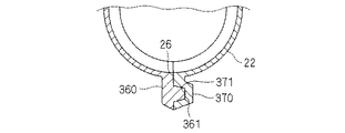
図11は第3変形例に係るフランジ部360、370を示す断面図である。この第3変形例では、一対のフランジ部360、370のうちの一方のフランジ部360にその延在方向に沿って延びる突条部361が形成され、他方のフランジ部370にその延在方向に沿って延びる凹条部371が形成されている。   FIG. 11 is a cross-sectional view showing flange portions 360 and 370 according to a third modification. In the third modified example, one flange portion 360 of the pair of flange portions 360 and 370 is formed with a protrusion 361 extending along the extending direction, and the other flange portion 370 is extended in the extending direction. A concave line portion 371 extending along the line is formed.

より具体的には、一方のフランジ部360は、コルゲートチューブ20のうちスリット26を挟む縁部の一方側から外方に突出するように形成されている。フランジ部360のうち他方のフランジ部370に面する側面に、上記突条部361が形成されている。   More specifically, one flange portion 360 is formed so as to protrude outward from one side of the edge portion sandwiching the slit 26 in the corrugated tube 20. The protruding portion 361 is formed on the side surface of the flange portion 360 that faces the other flange portion 370.

また、他方のフランジ部370は、コルゲートチューブ20のうちスリット26を挟む縁部の一方側から外方に突出するように形成されている。ここでは、両フランジ部360、370の突出長は同じであるが、必ずしも同じである必要はない。   The other flange portion 370 is formed so as to protrude outward from one side of the edge portion of the corrugated tube 20 sandwiching the slit 26. Here, the projecting lengths of the two flange portions 360 and 370 are the same, but they are not necessarily the same.

また、フランジ部370のうち他方のフランジ部360に面する側面に、上記凹条部371が形成されている。   Further, the concave portion 371 is formed on a side surface of the flange portion 370 facing the other flange portion 360.

突条部361及び凹条部371は、相互に対応する凹凸形状であり、突条部361を凹条部371に嵌め込みできるようになっている。嵌め込み状態において、突条部361及び凹条部371との間には隙間が無いことが好ましいが、これは必須ではなく、両者間に多少の隙間があってもよい。   The protruding portion 361 and the recessed portion 371 are concavo-convex shapes corresponding to each other, and the protruding portion 361 can be fitted into the recessed portion 371. In the fitted state, it is preferable that there is no gap between the protruding portion 361 and the recessed portion 371, but this is not essential, and there may be some gap between the two.

また、ここでは、突条部361の両側面は、その突出方向に向けて内側に傾斜しており、これに対応して凹条部371の両側面はその奥側に向けて内側に傾斜している。   Here, both side surfaces of the ridge portion 361 are inclined inward toward the protruding direction, and correspondingly, both side surfaces of the concave portion 371 are inclined inward toward the back side. ing.

従って、突条部361を凹条部371に容易に嵌め込めるようになっている。また、突条部361を凹条部371に嵌め込んだ状態で、突条部361の両側面と凹条部371の両側面との突き合せ面が、コルゲートチューブ20の内外方向に対して傾斜している。このため、スリット26を下向きに配設した状態で、突条部361の両側面と凹条部371の両側面との突き合せ面が鉛直方向に対して傾斜した姿勢となる。このため、上記第1及び第2変形例と同様の理由により、コルゲートチューブ20内の水が外部に排出され易い。   Therefore, the protrusion 361 can be easily fitted into the recess 371. In addition, in a state where the protrusion 361 is fitted in the recess 371, the abutting surfaces of the both sides of the protrusion 361 and the both sides of the recess 371 are inclined with respect to the inner and outer directions of the corrugated tube 20. is doing. For this reason, in a state where the slit 26 is disposed downward, the abutting surfaces of the both side surfaces of the protruding portion 361 and the both side surfaces of the recessed portion 371 are inclined with respect to the vertical direction. For this reason, the water in the corrugated tube 20 is easily discharged to the outside for the same reason as in the first and second modified examples.

この第3変形例によると、突条部361を凹条部371に嵌め込んで、一対のフランジ部360、370を突き合せることができる。このため、水、埃、ゴミ、砂等がフランジ部360、370間を通ってコルゲートチューブ20内に侵入し難い。   According to the third modification, the pair of flange portions 360 and 370 can be abutted with each other by fitting the protrusion 361 into the recess 371. For this reason, it is difficult for water, dust, dust, sand, and the like to enter the corrugated tube 20 through between the flange portions 360 and 370.

また、突条部361と凹条部371とを、相互にぴったりと嵌り合い、かつ、その摩擦力によって嵌り合い状態を維持できる程度の寸法設定とすることによって、スリット26を閉じた状態を維持することができる。この点からも、水、埃、ゴミ、砂等がフランジ部360、370間を通ってコルゲートチューブ20内に侵入し難い。   Also, the slit 26 is maintained in a closed state by setting the protrusions 361 and the concave portions 371 so as to fit closely to each other and maintain the fitting state by the frictional force. can do. Also from this point, it is difficult for water, dust, dust, sand, and the like to enter the corrugated tube 20 through the flange portions 360 and 370.

また、突条部361と凹条部371とが嵌り合うことによって、フランジ部360、370のずれを抑制することができる。これにより、フランジ部360、370同士の擦れ合いによるガタガタ音を抑制できる。   In addition, the protrusions 361 and the recesses 371 are fitted to each other, so that the displacement of the flanges 360 and 370 can be suppressed. Thereby, the rattling sound by the friction of the flange parts 360 and 370 can be suppressed.

<その他の変形例>
なお、上記実施形態では、コルゲートチューブ20を、ドア用配線装置10に適用した例で説明したが、コルゲートチューブ20はそのようなドア用配線だけでなく、各種配線箇所において当該配線を保護する部材としても用いることができる。
<Other variations>
In the above-described embodiment, the corrugated tube 20 has been described as an example applied to the door wiring device 10. However, the corrugated tube 20 is not only such a door wiring, but also a member that protects the wiring at various wiring locations. Can also be used.

また、上記実施形態では、コルゲートチューブ20が扁平な筒形状である例で説明したが、円筒状のコルゲートチューブに対しても上記と同様のフランジ部を形成することができる。   Moreover, although the corrugated tube 20 demonstrated in the said embodiment the example which is a flat cylinder shape, the flange part similar to the above can be formed also with respect to a cylindrical corrugated tube.

また、上記実施形態及び各変形例で説明した各構成は、相互に矛盾しない限り適宜組合わせることができる。例えば、図9に示す第1変形例において、図11に示す第3変形例のように、突条部及び凹条部を形成してもよい。   Moreover, each structure demonstrated by the said embodiment and each modification can be suitably combined unless it mutually contradicts. For example, in the first modification shown in FIG. 9, the protrusions and the recesses may be formed as in the third modification shown in FIG. 11.

以上のようにこの発明は詳細に説明されたが、上記した説明は、すべての局面において、例示であって、この発明がそれに限定されるものではない。例示されていない無数の変形例が、この発明の範囲から外れることなく想定され得るものと解される。   As described above, the present invention has been described in detail. However, the above description is illustrative in all aspects, and the present invention is not limited thereto. It is understood that countless variations that are not illustrated can be envisaged without departing from the scope of the present invention.

2 車体
6 ドア
10 ドア用配線装置
20 コルゲートチューブ
22 環状凸部
24 環状凹部
26 スリット
40 収容部
50 案内部
60、70,160、170,260、270,360、370 フランジ部
170a, 260a、270a 基部
170b,260b、270b 屈曲部分
361 突条部
371 凹条部
P プロテクタ
WH ワイヤーハーネス
2 Car body 6 Door 10 Wiring device for door 20 Corrugated tube 22 Annular convex part 24 Annular concave part 26 Slit 40 Storage part 50 Guide part 60, 70, 160, 170, 260, 270, 360, 370 Flange part 170a, 260a, 270a Base part 170b, 260b, 270b Bent part 361 Projection part 371 Concave part P Protector WH Wire harness

Claims (6)

環状凸部と環状凹部とが軸方向に沿って交互に連続的に形成されたコルゲートチューブであって、
前記軸方向に沿ってスリットが形成されると共に、前記スリットを挟む一対の縁部のそれぞれに、その延在方向に沿って外向きに突出するフランジ部が形成されたコルゲートチューブ。
A corrugated tube in which annular convex portions and annular concave portions are alternately and continuously formed along the axial direction,
A corrugated tube in which a slit is formed along the axial direction, and a flange portion that protrudes outward along the extending direction is formed on each of a pair of edge portions sandwiching the slit.
請求項1記載のコルゲートチューブであって、
前記一対のフランジ部のうちの一方の外側部分が、前記一対のフランジ部のうちの他方の外側部分に被さっている、コルゲートチューブ。
The corrugated tube according to claim 1,
A corrugated tube in which one outer portion of the pair of flange portions covers the other outer portion of the pair of flange portions.
請求項1又は請求項2記載のコルゲートチューブであって、
前記一対のフランジ部のうちの外側部分が、前記一対のフランジ部の内側部分に対して曲った状態で延出している、コルゲートチューブ。
The corrugated tube according to claim 1 or 2,
A corrugated tube in which an outer portion of the pair of flange portions extends in a bent state with respect to an inner portion of the pair of flange portions.
請求項1〜請求項3のいずれか1つに記載のコルゲートチューブであって、
前記一対のフランジ部の突き合せ形状が、その内側から外側に至る途中で斜めに曲っている、コルゲートチューブ。
The corrugated tube according to any one of claims 1 to 3,
The corrugated tube in which the butted shape of the pair of flange portions is bent obliquely on the way from the inside to the outside.
請求項1〜請求項4のいずれか1つに記載のコルゲートチューブであって、
前記一対のフランジ部のうちの一方に、その延在方向に沿って延びる突条部が形成され、前記一対のフランジ部のうちの他方に、その延在方向に沿って延びかつ前記突条部を嵌め込み可能な凹条部が形成されている、コルゲートチューブ。
The corrugated tube according to any one of claims 1 to 4,
One of the pair of flange portions is formed with a ridge extending along the extending direction, and the other of the pair of flange portions extends along the extending direction and the ridge. A corrugated tube in which a concave strip portion into which can be fitted is formed.
車体とドアとの間に配設されるドア用配線装置であって、
前記車体と前記ドアとの間に配索されるワイヤーハーネスと、
前記ワイヤーハーネスのうち前記車体と前記ドアとの間に架け渡される部分を囲うように配設された、請求項1〜請求項5のいずれか1つに記載のコルゲートチューブと、
前記コルゲートチューブのうち前記ドア側の端部を含む一部分の、前記ドア内における変位経路を案内する案内部と、前記ドア内において前記案内部に連なって設けられ、前記コルゲートチューブのうち前記ドア側の端部から延出する前記ワイヤーハーネスを余長吸収可能な状態で収容する収容部とを有するプロテクタと、
を備えるドア用配線装置。
A door wiring device disposed between a vehicle body and a door,
A wire harness routed between the vehicle body and the door;
The corrugated tube according to any one of claims 1 to 5, which is disposed so as to surround a portion of the wire harness that is bridged between the vehicle body and the door.
A portion of the corrugated tube including an end portion on the door side that guides a displacement path in the door, and is provided continuously to the guide portion in the door. A protector having an accommodating portion for accommodating the wire harness extending from the end of the wire harness in a state capable of absorbing the extra length;
A wiring device for doors.
JP2011046091A 2011-03-03 2011-03-03 Corrugate tube and door wiring device Withdrawn JP2012182964A (en)

Priority Applications (1)

Application Number Priority Date Filing Date Title
JP2011046091A JP2012182964A (en) 2011-03-03 2011-03-03 Corrugate tube and door wiring device

Applications Claiming Priority (1)

Application Number Priority Date Filing Date Title
JP2011046091A JP2012182964A (en) 2011-03-03 2011-03-03 Corrugate tube and door wiring device

Publications (1)

Publication Number Publication Date
JP2012182964A true JP2012182964A (en) 2012-09-20

Family

ID=47013684

Family Applications (1)

Application Number Title Priority Date Filing Date
JP2011046091A Withdrawn JP2012182964A (en) 2011-03-03 2011-03-03 Corrugate tube and door wiring device

Country Status (1)

Country Link
JP (1) JP2012182964A (en)

Cited By (2)

* Cited by examiner, † Cited by third party
Publication number Priority date Publication date Assignee Title
WO2015025894A1 (en) * 2013-08-20 2015-02-26 矢崎総業株式会社 External member
US10193316B2 (en) 2016-09-12 2019-01-29 Yazaki Corporation Corrugated tube and wire harness

Cited By (3)

* Cited by examiner, † Cited by third party
Publication number Priority date Publication date Assignee Title
WO2015025894A1 (en) * 2013-08-20 2015-02-26 矢崎総業株式会社 External member
JP2015042041A (en) * 2013-08-20 2015-03-02 矢崎総業株式会社 Exterior member
US10193316B2 (en) 2016-09-12 2019-01-29 Yazaki Corporation Corrugated tube and wire harness

Similar Documents

Publication Publication Date Title
WO2012070268A1 (en) Wire harness cable routing structure and protector
US7202415B2 (en) Wire harness construction
WO2013031260A1 (en) Harness protector and wire harness routing structure section
JP5644596B2 (en) Wire harness wiring structure
JP4706408B2 (en) Wire harness wiring structure
WO2013008486A1 (en) Wire harness routing structural part
US9511725B2 (en) Wiring harness wiring structure
JP2013247805A (en) Wire harness routing structure
WO2012114547A1 (en) Wire-harness wiring structure
JP5549558B2 (en) Wire harness routing structure
JP5634807B2 (en) Power supply device
WO2012147223A1 (en) Wire harness routing structure
JP2012182964A (en) Corrugate tube and door wiring device
JP2013226961A (en) Wire harness routing structure part
JP5799937B2 (en) Grommet and wiring harness wiring structure
WO2012150643A1 (en) Wire harness routing structure section
JP5630307B2 (en) Wire harness wiring structure
WO2012120719A1 (en) Wire harness routing structure
JP5445410B2 (en) Wire harness routing structure
WO2012127723A1 (en) Door wiring device
JP4412150B2 (en) Wiring harness wiring structure using grommets
JP2012178907A (en) Cable routing structure for wire harnesses
WO2012114551A1 (en) Wire harness routing structure
JP2012111401A (en) Wiring harness cable routing structure
JP5853932B2 (en) Wire harness wiring structure

Legal Events

Date Code Title Description
A300 Withdrawal of application because of no request for examination

Free format text: JAPANESE INTERMEDIATE CODE: A300

Effective date: 20140513