JP2012181532A - Optical scanner - Google Patents
Optical scanner Download PDFInfo
- Publication number
- JP2012181532A JP2012181532A JP2012092564A JP2012092564A JP2012181532A JP 2012181532 A JP2012181532 A JP 2012181532A JP 2012092564 A JP2012092564 A JP 2012092564A JP 2012092564 A JP2012092564 A JP 2012092564A JP 2012181532 A JP2012181532 A JP 2012181532A
- Authority
- JP
- Japan
- Prior art keywords
- substrate
- housing
- optical
- scanning
- light beam
- Prior art date
- Legal status (The legal status is an assumption and is not a legal conclusion. Google has not performed a legal analysis and makes no representation as to the accuracy of the status listed.)
- Pending
Links
Images


Landscapes
- Facsimile Scanning Arrangements (AREA)
- Laser Beam Printer (AREA)
- Mechanical Optical Scanning Systems (AREA)
- Exposure Or Original Feeding In Electrophotography (AREA)
Abstract
Description
本発明は、カラー複写機やカラープリンタ等のカラー画像形成装置に備えられる光走査装置に関するものである。 The present invention relates to an optical scanning device provided in a color image forming apparatus such as a color copying machine or a color printer.
複写機やプリンタ等の画像形成装置においては、帯電器によって表面が一様に帯電された感光体が光走査装置によって光走査され、その表面に画像情報に応じた静電潜像が形成される。そして、静電潜像は現像装置によって現像剤であるトナーを用いて現像されてトナー像として顕像化され、このトナー像は、転写装置によって用紙上に転写された後に定着装置によって加熱及び加圧されて用紙上に定着され、トナー像が定着された用紙が装置外へ排出されることによって一連の画像形成動作が終了する。 In an image forming apparatus such as a copying machine or a printer, a photoconductor whose surface is uniformly charged by a charger is optically scanned by an optical scanning device, and an electrostatic latent image corresponding to image information is formed on the surface. . The electrostatic latent image is developed by a developing device using toner as a developer to be visualized as a toner image. The toner image is transferred onto a sheet by a transfer device and then heated and heated by a fixing device. A series of image forming operations is completed by discharging the sheet having the toner image fixed thereon by being pressed and fixed on the sheet.
ところで、感光体を光走査してその表面に静電潜像を形成する光走査装置は、光源から出射される光ビームを偏向するポリゴンミラー等の偏向器と、該偏向器によって偏向された光ビームを等速走査光に変換する結像レンズと等速走査光を折り返して感光体に導く複数の反射ミラーを備えた走査光学系をハウジング内に収容して構成されている。 By the way, an optical scanning device that optically scans a photoconductor to form an electrostatic latent image on the surface thereof includes a deflector such as a polygon mirror that deflects a light beam emitted from a light source, and light deflected by the deflector. A scanning optical system including an imaging lens that converts a beam into constant speed scanning light and a plurality of reflecting mirrors that fold back the constant speed scanning light and guide it to the photosensitive member is housed in a housing.
斯かる光走査装置に関して、例えば特許文献1には、単一の偏向器をハウジング内の中央に配置し、該偏向器によって光ビームを対称な2方向に振り分けて偏向する構成が提案されている。 With regard to such an optical scanning device, for example, Patent Document 1 proposes a configuration in which a single deflector is arranged in the center of the housing and the light beam is distributed and deflected in two symmetrical directions by the deflector. .
又、特許文献2には、偏向器を中心とする対称な2方向に1本ずつの光ビームを走査するハウジング(光学箱)を2つ並設した光走査装置が提案されている。この光走査装置によれば、1つのハウジングが小さくなるため、走査線の位置ズレが小さく抑えられて色ズレの問題が発生しにくくなる。又、折り返しミラーの枚数を1枚とすることによって、折り返しミラーによる色ズレへの影響を低減することができる。 Patent Document 2 proposes an optical scanning device in which two housings (optical boxes) for scanning one light beam in two symmetrical directions around a deflector are arranged side by side. According to this optical scanning device, since one housing is small, the positional deviation of the scanning line is suppressed to be small, and the problem of color deviation is less likely to occur. Further, by setting the number of folding mirrors to one, it is possible to reduce the influence of the folding mirrors on color misregistration.
しかしながら、特許文献1において提案された構成では、片方向に2本の光ビームを走査しており、2本の光ビームを分離して感光体に導く必要があるため、ハウジング内に高さ方向の空間を確保する必要があり、ハウジングが大型化するという問題がある。又。2本の光ビームを等速走査するために設けられた結像レンズの高さ方向の幅を大きく取る必要があり、コストアップを避けることができない。更に、4本の光ビームを走査するための4つの光学系を全て1つのハウジング内に収容しているため、ハウジングが大きくなってしまう。このため、温度変化によるハウジングの熱変形量が大きくなり、光ビームの走査位置がずれて色ズレの問題が発生し易い。 However, in the configuration proposed in Patent Document 1, two light beams are scanned in one direction, and it is necessary to separate the two light beams and guide them to the photosensitive member. There is a problem that the housing needs to be secured and the housing becomes large. or. It is necessary to increase the width in the height direction of the imaging lens provided to scan the two light beams at a constant speed, and an increase in cost cannot be avoided. Furthermore, since all four optical systems for scanning four light beams are accommodated in one housing, the housing becomes large. For this reason, the amount of thermal deformation of the housing due to a temperature change increases, and the scanning position of the light beam shifts and a problem of color misregistration tends to occur.
又、特許文献2において提案された光走査装置では、偏向器から感光体までの光路の折り返しが1回であるため、ハウジングの高さ方向の幅が大きくなるという問題がある。特に、焦点距離が長い結像レンズを用いた場合には、その焦点距離に比例してハウジングの高さが大きくなってしまい、ハウジングが大型化する。 In addition, the optical scanning device proposed in Patent Document 2 has a problem that the width in the height direction of the housing increases because the optical path from the deflector to the photosensitive member is folded once. In particular, when an imaging lens having a long focal length is used, the height of the housing increases in proportion to the focal length, which increases the size of the housing.
本発明は上記問題に鑑みてなされたもので、その目的とする処は、小型化を図ることができるとともに、カラー画像形成装置の4つの感光体間のピッチを略均等化することができる光走査装置を提供することにある。 The present invention has been made in view of the above problems, and an object of the present invention is light that can reduce the size and can substantially equalize the pitch between the four photoconductors of the color image forming apparatus. It is to provide a scanning device.
上記目的を達成するため、本発明は、カラー画像形成装置の用紙搬送方向に2台並列に配置される光走査装置において、
光源から出射される光ビームを偏向する偏向器と、該偏向器によって偏向された光ビームを等速走査光に変換する結像レンズと等速走査光を折り返して感光体に導く第1、第2及び第3反射ミラーを備えた2つの走査光学系を前記偏向器を中心としてハウジング内に対称に配置し、
前記ハウジングに該ハウジング内を上下に区画する基板を形成し、該基板の一方の面に前記偏向器及び前記走査光学系の結像レンズと第1反射ミラーを光ビームの進行方向に沿って配置するとともに、同基板の他方の面に前記走査光学系の第2及び第3反射ミラーを光ビームの進行方向に沿って配置し、
前記基板の前記第3反射ミラーと前記感光体を結ぶ光路上であって且つ前記結像レンズと前記第1反射ミラーの間に第1の開口部を形成し、同基板の前記第1反射ミラーと第2反射ミラーを結ぶ光路上に第2の開口部を形成したことを特徴とする。
To achieve the above object, the present invention provides an optical scanning device arranged in parallel in the paper transport direction of a color image forming apparatus,
A deflector that deflects a light beam emitted from a light source, an imaging lens that converts the light beam deflected by the deflector to constant-speed scanning light, and first and second light sources that return the constant-speed scanning light to the photoreceptor. Two scanning optical systems having two and third reflecting mirrors are arranged symmetrically in the housing with the deflector as a center;
A substrate for vertically dividing the inside of the housing is formed in the housing, and the deflector, the imaging lens of the scanning optical system, and the first reflecting mirror are arranged on one surface of the substrate along the traveling direction of the light beam. And the second and third reflecting mirrors of the scanning optical system are arranged along the traveling direction of the light beam on the other surface of the substrate,
A first opening is formed on the optical path connecting the third reflection mirror of the substrate and the photosensitive member and between the imaging lens and the first reflection mirror, and the first reflection mirror of the same substrate A second opening is formed on the optical path connecting the first reflecting mirror and the second reflecting mirror.
本発明によれば、偏向器によって偏向された光ビームが反射ミラーによって折り返されてハウジングの基板の上面と下面に沿って進行するため、ハウジングの高さ方向の幅が小さく抑えられて該ハウジングの小型化が図られる。 According to the present invention, the light beam deflected by the deflector is folded back by the reflecting mirror and travels along the upper surface and the lower surface of the substrate of the housing, so that the width in the height direction of the housing is suppressed to be small. Miniaturization is achieved.
又、偏向器を中心として2つの走査光学系を対称に配置することによって1台の光走査装置によって2つの感光体を同時に光走査することができる。 Further, by arranging the two scanning optical systems symmetrically with the deflector as the center, two photoconductors can be simultaneously scanned by one optical scanning device.
更に、2つの感光体を同時に光走査することができる2台の光走査装置をカラー画像形成装置に並設したため、4色(マゼンタ、シアン、イエロー及びブラック)の画像情報に応じた光ビームによって計4つの感光体が光走査されるが、各光走査装置のハウジングに形成された基板の第3反射ミラーと感光体を結ぶ光路上であって且つ結像レンズと第1反射ミラーの間に第1の開口部を形成したため、4つの感光体間のピッチを略均等化することができる。 Furthermore, since two optical scanning devices capable of simultaneously scanning two photoconductors are provided side by side in the color image forming apparatus, a light beam corresponding to image information of four colors (magenta, cyan, yellow and black) is used. A total of four photoconductors are optically scanned, and are on the optical path connecting the third reflection mirror of the substrate formed on the housing of each optical scanning device and the photoconductor and between the imaging lens and the first reflection mirror. Since the first opening is formed, the pitch between the four photoconductors can be substantially equalized.
以下に本発明の実施の形態を添付図面に基づいて説明する。 Embodiments of the present invention will be described below with reference to the accompanying drawings.
[画像形成装置]
図1はカラー画像形成装置の一形態としてのカラーレーザープリンタの断面図であり、図示のカラーレーザープリンタはタンデム型であって、その本体100内の中央部には、マゼンタ画像形成ユニット1M、シアン画像形成ユニット1C、イエロー画像形成ユニット1Y及びブラック画像形成ユニット1Kが一定の間隔でタンデムに配置されている。
[Image forming apparatus]
FIG. 1 is a cross-sectional view of a color laser printer as an embodiment of a color image forming apparatus. The illustrated color laser printer is a tandem type, and a magenta
上記各画像形成ユニット1M,1C,1Y,1Kには、感光体である感光ドラム2a,2b,2c,2dがそれぞれ配置されており、各感光ドラム2a〜2dの周囲には、帯電器3a,3b,3c,3d、現像装置4a,4b,4c,4d、転写ローラ5a,5b,5c,5d及びドラムクリーニング装置6a,6b,6c,6dがそれぞれ配置されている。
In each of the
ここで、前記感光ドラム2a〜2dは、ドラム状の感光体であって、不図示の駆動モータによって図示矢印方向(時計方向)に所定のプロセススピードで回転駆動される。又、前記帯電器3a〜3dは、不図示の帯電バイアス電源から印加される帯電バイアスによって感光ドラム2a〜2dの表面を所定の電位に均一に帯電させるものである。
Here, the
更に、前記現像装置4a〜4dは、マゼンタ(M)トナー、シアン(C)トナー、イエロー(Y)トナー、ブラック(K)トナーをそれぞれ収容しており、各感光ドラム2a〜2d上に形成された各静電潜像に各色のトナーを付着させて各静電潜像を各色のトナー像として可視像化するものである。
Further, the developing
又、前記転写ローラ5a〜5dは、各一次転写部にて中間転写ベルト7を介して各感光ドラム2a〜2dに当接可能に配置されている。ここで、中間転写ベルト7は、駆動ローラ8とテンションローラ9との間に張設されて各感光ドラム2a〜2dの上面側に走行可能に配置されており、前記駆動ローラ8は、二次転写部において中間転写ベルト7を介して二次転写ローラ10に当接可能に配置されている。又、テンションローラ9の近傍にはベルトクリーニング装置11が設けられている。
The
ところで、プリンタ本体100内の各画像形成ユニット1M,1C,1Y,1Kの上方には、前記各現像装置4a〜4dにトナーを補給するためのトナーコンテナ12a,12b,12c,12dが一列に並設されている。
Incidentally,
又、プリンタ本体100内の各画像形成ユニット1M,1C,1Y,1Kの下方には、2台の光走査装置13が用紙搬送方向に並設され、これらの光走査装置13の下方のプリンタ本体100の底部には給紙カセット14が着脱可能に設置されている。そして、給紙カセット14には複数枚の不図示の用紙が積層収容されており、この給紙カセット14の近傍には、該給紙カセット14から用紙を取り出すピックアップローラ15と、取り出された用紙を分離して搬送パスSへと1枚ずつ送り出すフィードローラ16とリタードローラ17が設けられている。
Further, below the
又、プリンタ本体100の側部を上下方向に延びる前記搬送パスSには、用紙を搬送する搬送ローラ対18と、用紙を一時待機させた後に所定のタイミングで前記二次転写対向ローラ8と二次転写ローラ10との当接部である二次転写部へと供給するレジストローラ対19が設けられている。尚、搬送パスSの横には、用紙の両面に画像を形成する場合に使用される別の搬送パスS’が形成されており、この搬送パスS’には複数の反転ローラ対20が適当な間隔で設けられている。
Further, the conveyance path S extending in the vertical direction on the side of the printer
ところで、プリンタ本体100内の一側部に縦方向に配置された前記搬送パスSは、プリンタ本体100の上面に設けられた排紙トレイ21まで延びており、その途中には定着装置22と排紙ローラ対23,24が設けられている。
By the way, the conveyance path S arranged in the vertical direction on one side of the printer
次に、以上の構成を有するカラーレーザープリンタによる画像形成動作について説明する。 Next, an image forming operation by the color laser printer having the above configuration will be described.
画像形成開始信号が発せられると、各画像形成ユニット1M,1C,1Y,1Kにおいて各感光ドラム2a〜2dが図示矢印方向(時計方向)に所定のプロセススピードで回転駆動され、これらの感光ドラム2a〜2dは、帯電器3a〜3dによって一様に帯電される。又、各光走査装置13は、各色毎のカラー画像信号によって変調された光ビームを出射し、その光ビームを各感光ドラム2a〜2dの表面に照射し、各感光ドラム2a〜2d上に各色のカラー画像信号に対応した静電潜像をそれぞれ形成する。
When an image formation start signal is issued, the
そして、先ず、マゼンタ画像形成ユニット1Mの感光ドラム2a上に形成された静電潜像に、該感光ドラム2aの帯電極性と同極性の現像バイアスが印加された現像装置4aによってマゼンタトナーを付着させ、該静電潜像をマゼンタトナー像として可視像化する。このマゼンタトナー像は、感光ドラム2aと転写ローラ5aとの間の一次転写部(転写ニップ部)において、トナーと逆極性の一次転写バイアスが印加された転写ローラ5aの作用によって、図示矢印方向に回転駆動されている中間転写ベルト7上に一次転写される。
First, magenta toner is attached to the electrostatic latent image formed on the
上述のようにしてマゼンタトナー像が一次転写された中間転写ベルト7は、次のシアン画像形成ユニット1Cへと移動する。そして、シアン画像形成ユニット1Cにおいても、前記と同様にして、感光ドラム2b上に形成されたシアントナー像が一次転写部において中間転写ベルト7上のマゼンタトナー像に重ねて転写される。
The intermediate transfer belt 7 on which the magenta toner image has been primarily transferred as described above moves to the next cyan image forming unit 1C. In the cyan image forming unit 1C as well, the cyan toner image formed on the
以下同様にして、中間転写ベルト7上に重畳転写されたマゼンタ及びシアントナー像の上に、イエロー及びブラック画像形成ユニット1Y,1Kの各感光ドラム2c,2d上にそれぞれ形成されたイエロー及びブラックトナー像が各一次転写部において順次重ね合わせられ、中間転写ベルト7上にはフルカラーのトナー像が形成される。尚、中間転写ベルト7上に転写されないで各感光ドラム2a〜2d上に残留する転写残トナーは、各ドラムクリーニング装置6a〜6dによって除去され、各感光ドラム2a〜2dは次の画像形成に備えられる。
Similarly, yellow and black toners respectively formed on the
そして、中間転写ベルト7上のフルカラートナー像の先端が駆動ローラ8と二次転写ローラ10間の二次転写部(転写ニップ部)に達するタイミングに合わせて、給紙カセット14からピックアップローラ15とフィードローラ16及びリタードローラ17によって搬送パスSへと送り出された用紙がレジストローラ対19によって二次転写部へと搬送される。そして、二次転写部に搬送された用紙に、トナーと逆極性の二次転写バイアスが印加された二次転写ローラ10によってフルカラーのトナー像が中間転写ベルト7から一括して二次転写される。
Then, in accordance with the timing at which the front end of the full-color toner image on the intermediate transfer belt 7 reaches the secondary transfer portion (transfer nip portion) between the drive roller 8 and the
而して、フルカラーのトナー像が転写された用紙は、定着装置22へと搬送され、フルカラーのトナー像が加熱及び加圧されて用紙の表面に熱定着され、トナー像が定着された用紙は、排紙ローラ対23,24によって排紙トレイ21上に排出されて一連の画像形成動作が完了する。尚、用紙上に転写されないで中間転写ベルト7上に残留する転写残トナーは、前記ベルトクリーニング装置11によって除去され、中間転写ベルト7は次の画像形成に備えられる。
Thus, the sheet on which the full-color toner image has been transferred is conveyed to the fixing
[光走査装置]
次に、本発明に係る前記光走査装置13を図2及び図3に基づいて説明する。尚、図2は本発明に係る光走査装置1台の主走査断面図、図3は光走査装置2台の副走査断面図である。
[Optical scanning device]
Next, the
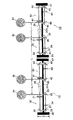
図3に示す2台の光走査装置13の基本構成は同じであるため、1台の光装置装置13の構成を図2に基づいて説明すると、光走査装置13は、樹脂にて一体成形されたハウジング25を有しており、該ハウジング25には、その内部を上下に区画する水平な基板25Aが一体に形成されている。そして、ハウジング25の基板25Aの上面の中心部には偏向器であるポリゴンミラー26が配置されており、ハウジング25内の基板25Aの上面と下面には前記ポリゴンミラー26を中心としてこれの両側に2つの走査光学系30,40が対称に配置されている。
Since the basic configuration of the two
上記走査光学系30,40は、ハウジング25内の基板25Aの上面に光ビームの進行方向に沿って配された第1結像レンズ31,41及び第1反射ミラー32,42と、基板25Aの下面に光ビームの進行方向に沿って配された第2反射ミラー33,43と第2結像レンズ34,44及び第3反射ミラー34,45をそれぞれ備えている。尚、図示しないが、各走査光学系30,40は、ハウジング25内に収容された光源としてのレーザーダイオードとコリメータレンズ及びシリンドリカルレンズも備えている。
The scanning
ところで、図2に示す1台の光走査装置13は、図1に示すマゼンタ画像形成ユニット1Mの感光ドラム2aとシアン画像形成ユニット1Cの感光ドラム2bを露光走査するものであって、各走査光学系30,40を構成する第3反射ミラー35,45と感光ドラム2a,2bを結ぶ光路上であって且つ第1結像レンズ31,41と第1反射ミラー32,42の間には第1の開口部36,46がそれぞれ形成され、基板25Aの第1反射ミラー32,42と第2反射ミラー33,43を結ぶ光路上には第2の開口部37,47がそれぞれ形成されている。
Incidentally, one
而して、1台の光走査装置13において各走査光学系30,40に設けられた不図示のレーザーダイオードから出射する光ビームは、不図示のコリメータレンズとシリンドリカルレンズによって線状の光束に集光された後、回転駆動されるポリゴンミラー26に対して対称な2方向から入射する。
Thus, a light beam emitted from a laser diode (not shown) provided in each of the scanning
上述のようにポリゴンミラー26に入射した各光ビームは、ポリゴンミラー26によって偏向された後、第1結像レンズ31,41を通過することによって等速走査光に変換される。そして、この等速走査光は、第1反射ミラー32,42によって下方に向かって直角に折り返され、基板25Aに形成された第2の開口部37,47を通過して第2反射ミラー33,43に至り、該第2反射ミラー33,43によって直角に折り返されて基板25Aの下面に沿って水平に進行する。その後、光ビームは第2結像レンズ34,44を通過して第3反射ミラー35,45に至り、該第3反射ミラー35,45によって直角上方に折り返され、基板25Aに形成された第1の開口部36,46を通過して感光ドラム2a,2bに向かい、これらの感光ドラム2a,2bをそれぞれ露光走査する。
As described above, each light beam incident on the
図2に示す1台の光走査装置13は、図1に示すマゼンタ画像形成ユニット1Mの感光ドラム2aとシアン画像形成ユニット1Cの感光ドラム2bを露光走査するものであるが、図1に示すカラーレーザープリンタには図3に示すように同様の光走査装置13が2台並設されており、これら2台の光走査装置13によって他のイエロー画像形成ユニット1Y及びブララック画像形成ユニット1Kの各感光ドラム2c,2dを含む4つの感光ドラム2a〜2dの全てが光ビームによって露光走査される。尚、図3においては、2台の光走査装置13を構成する同一要素には同一符号を付している。
The one
以上において、本発明に係る光走査装置13においては、ポリゴンミラー26によって偏向された光ビームが第1反射ミラー32,42及び第2反射ミラー33,43によって折り返されてハウジング25の基板25Aの上面と下面に沿って進行するため、ハウジング25の高さ方向の幅が小さく抑えられて該ハウジング25の小型化、延いては光走査装置13全体の小型化が図られる。
As described above, in the
又、本実施の形態では、ハウジング25内の中心に配置されたポリゴンミラー26を中心としてこれの両側に2つの走査光学系30,40を対称に配置したため、1台の光走査装置13によって2つの感光ドラム2a,2b又は2c,2dを同時に光走査することができる。
In the present embodiment, since the two scanning
そして、上述のように4つの感光ドラム2a〜2dを同時に光走査することができる2台の光走査装置13を図1に示すカラーレーザープリンタに並設したため、4色(マゼンタ、シアン、イエロー及びブラック)の画像情報に応じた光ビームによって計4つの感光ドラム2a〜2dが光走査されるが、各光走査装置13のハウジング25に形成された基板25Aの第3反射ミラー35,45と感光ドラム2a〜2dを結ぶ光路上であって且つ第1結像レンズ31,41と第1反射ミラー32,42の間に第1の開口部36,46を形成したため、4つの感光ドラム2a〜2d間のピッチL,L’を略均等化することができるとともに、基板25Aの下面側の折り返し光路の導光距離を最大限に利用することができる。
Since the two
因に、図4に示すように、第1の開口部36,46をポリゴンミラー26と第1結像レンズ31,41の間に形成した場合には、第2反射ミラー33,43と第3反射ミラー35,45の折り返しの光路を長く取ることができるが、一般に第1結像レンズ31,41はポリゴンミラー26の近傍に配置されることが多く、このような構成を採用した場合には各光走査装置13’における感光ドラム2aと2b間及び2cと2d間のピッチLが短くなってしまう。このため、両光走査装置13’を図示のように用紙の搬送方向に並設すると、感光ドラム2bと2c間のピッチL’がピッチLに対して大きくなり、4色の感光ドラム2a〜2d間のピッチL,L’を均等化することが困難となってしまう。
Incidentally, as shown in FIG. 4, when the
4色の感光ドラム2a〜2d間のピッチL,L’を均等化するには、感光ドラム2bと2c間のピッチL’を小さくすれば良いが、感光ドラム2bと2c間のピッチL’を小さくするには図5に示す構成を採用する必要があり、このような構成では各光走査装置13”のハウジング25の高さ方向の幅D’が図3及び図4に示す光走査装置13,13’の幅Bよりも大きくなってしまい(D’≫D)、ハウジング25が大型化するという問題が発生する。
In order to equalize the pitches L and L ′ between the four color
尚、以上は本発明をカラーレーザープリンタに備えられた光走査装置に対して適用した形態について説明したが、本発明は、カラープリンタ以外のカラー複写機等の他の任意のカラー画像形成装置に備えられた光走査装置に対しても同様に適用可能であることは勿論である。 Although the present invention has been described with respect to an embodiment in which the present invention is applied to an optical scanning device provided in a color laser printer, the present invention is applicable to any other color image forming apparatus such as a color copying machine other than a color printer. Of course, the present invention can be similarly applied to the optical scanning device provided.
1M マゼンタ画像形成ユニット
1C シアン画像形成ユニット
1Y イエロー画像形成ユニット
1K ブラック画像形成ユニット
2a〜2d 感光ドラム(感光体)
3a〜3d 帯電器
4a〜4d 現像装置
5a〜5d 転写ローラ
6a〜6d ドラムクリーニング装置
7 中間転写ベルト
8 駆動ローラ
9 テンションローラ
10 二次転写ローラ
11 ベルトクリーニング装置
12a〜12d トナーコンテナ
13 光走査装置
14 給紙カセット
15 ピックアップローラ
16 フィードローラ
17 リタードローラ
18 搬送ローラ対
19 レジストローラ対
20 搬送ローラ対
21 排紙トレイ
22 定着装置
23,24 排紙ローラ対
25 ハウジング
25A ハウジングの基板
26 ポリゴンミラー(偏向器)
30,40 走査光学系
31,41 第1結像レンズ
32,42 第1反射ミラー
33,43 第2反射ミラー
34,44 第2結像レンズ
35,45 第3反射ミラー
36,46 第1の開口部
37,47 第2の開口部
D ハウジングの高さ方向の幅
L,L’ 感光ドラム間のピッチ
S,S’ 搬送パス
1M Magenta image forming unit 1C Cyan
3a to
30, 40 Scanning
Claims (1)
光源から出射される光ビームを偏向する偏向器と、該偏向器によって偏向された光ビームを等速走査光に変換する結像レンズと等速走査光を折り返して感光体に導く第1、第2及び第3反射ミラーを備えた2つの走査光学系を前記偏向器を中心としてハウジング内に対称に配置し、
前記ハウジングに該ハウジング内を上下に区画する基板を形成し、該基板の一方の面に前記偏向器及び前記走査光学系の結像レンズと第1反射ミラーを光ビームの進行方向に沿って配置するとともに、同基板の他方の面に前記走査光学系の第2及び第3反射ミラーを光ビームの進行方向に沿って配置し、
前記基板の前記第3反射ミラーと前記感光体を結ぶ光路上であって且つ前記結像レンズと前記第1反射ミラーの間に第1の開口部を形成し、同基板の前記第1反射ミラーと第2反射ミラーを結ぶ光路上に第2の開口部を形成したことを特徴とする光走査装置。
In the optical scanning device arranged in parallel in the paper conveyance direction of the color image forming apparatus,
A deflector that deflects a light beam emitted from a light source, an imaging lens that converts the light beam deflected by the deflector to constant-speed scanning light, and first and second light sources that return the constant-speed scanning light to the photoreceptor. Two scanning optical systems having two and third reflecting mirrors are arranged symmetrically in the housing with the deflector as a center;
A substrate for vertically dividing the inside of the housing is formed in the housing, and the deflector, the imaging lens of the scanning optical system, and the first reflecting mirror are arranged on one surface of the substrate along the traveling direction of the light beam. And the second and third reflecting mirrors of the scanning optical system are arranged along the traveling direction of the light beam on the other surface of the substrate,
A first opening is formed on the optical path connecting the third reflection mirror of the substrate and the photosensitive member and between the imaging lens and the first reflection mirror, and the first reflection mirror of the same substrate An optical scanning device characterized in that a second opening is formed on an optical path connecting the first reflection mirror and the second reflection mirror.
Priority Applications (1)
| Application Number | Priority Date | Filing Date | Title |
|---|---|---|---|
| JP2012092564A JP2012181532A (en) | 2012-04-16 | 2012-04-16 | Optical scanner |
Applications Claiming Priority (1)
| Application Number | Priority Date | Filing Date | Title |
|---|---|---|---|
| JP2012092564A JP2012181532A (en) | 2012-04-16 | 2012-04-16 | Optical scanner |
Related Parent Applications (1)
| Application Number | Title | Priority Date | Filing Date |
|---|---|---|---|
| JP2009271156A Division JP5090429B2 (en) | 2009-11-30 | 2009-11-30 | Color image forming apparatus |
Publications (1)
| Publication Number | Publication Date |
|---|---|
| JP2012181532A true JP2012181532A (en) | 2012-09-20 |
Family
ID=47012722
Family Applications (1)
| Application Number | Title | Priority Date | Filing Date |
|---|---|---|---|
| JP2012092564A Pending JP2012181532A (en) | 2012-04-16 | 2012-04-16 | Optical scanner |
Country Status (1)
| Country | Link |
|---|---|
| JP (1) | JP2012181532A (en) |
Cited By (1)
| Publication number | Priority date | Publication date | Assignee | Title |
|---|---|---|---|---|
| JP2014191286A (en) * | 2013-03-28 | 2014-10-06 | Brother Ind Ltd | Scanning optical device |
-
2012
- 2012-04-16 JP JP2012092564A patent/JP2012181532A/en active Pending
Cited By (1)
| Publication number | Priority date | Publication date | Assignee | Title |
|---|---|---|---|---|
| JP2014191286A (en) * | 2013-03-28 | 2014-10-06 | Brother Ind Ltd | Scanning optical device |
Similar Documents
| Publication | Publication Date | Title |
|---|---|---|
| JP2010256397A (en) | Optical scanning apparatus and image forming apparatus with the same | |
| US9199480B2 (en) | Optical scanning device and image forming apparatus using same | |
| JP5150568B2 (en) | Optical scanning apparatus and image forming apparatus having the same | |
| JP5289406B2 (en) | Optical scanning device and image forming apparatus having the same | |
| JP2012181532A (en) | Optical scanner | |
| JP6031418B2 (en) | Optical scanning device and image forming apparatus using the same | |
| JP5090429B2 (en) | Color image forming apparatus | |
| JP2018136475A (en) | Scanning optical device | |
| JP2013205525A (en) | Optical scanner and image forming apparatus provided with the same | |
| US8525865B2 (en) | Optical scanning apparatus and image forming apparatus provided with the same | |
| JP2011137922A (en) | Optical scanner and image forming apparatus equipped with the same | |
| JP5302923B2 (en) | Optical scanning device and image forming apparatus having the same | |
| JP5401482B2 (en) | Optical scanning device and image forming apparatus having the same | |
| JP2011137925A (en) | Optical scanning device and image forming apparatus equipped with the same | |
| JP2011158496A (en) | Optical scanner and image forming apparatus equipped with the same | |
| JP2012155248A (en) | Optical scanning device and image formation device having the same | |
| JP2012073458A (en) | Optical scanner and image forming apparatus equipped with the same | |
| JP7246245B2 (en) | OPTICAL SCANNER AND IMAGE FORMING APPARATUS INCLUDING THE SAME | |
| JP5254272B2 (en) | Lens mounting structure, optical scanning device and image forming apparatus provided with the same | |
| JP5683401B2 (en) | Optical scanning device and image forming apparatus having the same | |
| JP5439397B2 (en) | Optical scanning device and image forming apparatus having the same | |
| JP4898605B2 (en) | Optical writing apparatus and image forming apparatus | |
| JP2011137924A (en) | Optical scanner and image forming apparatus provided with the same | |
| JP6428654B2 (en) | Optical scanning device and image forming apparatus | |
| US8698866B2 (en) | Optical scanning device and image forming apparatus provided with the same |
Legal Events
| Date | Code | Title | Description |
|---|---|---|---|
| A131 | Notification of reasons for refusal |
Free format text: JAPANESE INTERMEDIATE CODE: A132 Effective date: 20121107 |
|
| RD04 | Notification of resignation of power of attorney |
Free format text: JAPANESE INTERMEDIATE CODE: A7424 Effective date: 20130808 |
|
| A02 | Decision of refusal |
Free format text: JAPANESE INTERMEDIATE CODE: A02 Effective date: 20130828 |