JP2012180864A - Cylinder device, and method of manufacturing the same - Google Patents
Cylinder device, and method of manufacturing the same Download PDFInfo
- Publication number
- JP2012180864A JP2012180864A JP2011042855A JP2011042855A JP2012180864A JP 2012180864 A JP2012180864 A JP 2012180864A JP 2011042855 A JP2011042855 A JP 2011042855A JP 2011042855 A JP2011042855 A JP 2011042855A JP 2012180864 A JP2012180864 A JP 2012180864A
- Authority
- JP
- Japan
- Prior art keywords
- rod guide
- seal ring
- cylinder
- closing member
- outer cylinder
- Prior art date
- Legal status (The legal status is an assumption and is not a legal conclusion. Google has not performed a legal analysis and makes no representation as to the accuracy of the status listed.)
- Abandoned
Links
Images


Landscapes
- Fluid-Damping Devices (AREA)
Abstract
Description
本発明は、シリンダ装置およびその製造方法に関する。 The present invention relates to a cylinder device and a manufacturing method thereof.
シリンダ装置において、外筒とロッドガイドとの間にシールリングを設けたものがある(例えば、特許文献1参照)。
また、別のシリンダ装置として、ロッドガイドの外側のキャップ体で外筒の端部を閉塞するものがある(例えば、特許文献2参照)。
Some cylinder devices are provided with a seal ring between an outer cylinder and a rod guide (see, for example, Patent Document 1).
As another cylinder device, there is one that closes the end of the outer cylinder with a cap body outside the rod guide (see, for example, Patent Document 2).
上記の特許文献1に示すシールリングを有するシリンダ装置では、シールリングが金属製の円環状部材に一体化されており、シリンダの端部は、前記円環状部材に向けて径方向内方に屈曲させることで閉塞している。また、特許文献2に示すキャップ体で外筒の端部を閉塞するものは、シリンダとキャップ体とを溶接等で閉塞する必要がある。さらに、シールリングを円環状部材などと一体化することなく、単独で組み付けられる構造の場合、組み付けの作業性が良くないという問題があった。 In the cylinder device having the seal ring shown in Patent Document 1, the seal ring is integrated with a metal annular member, and the end of the cylinder is bent radially inward toward the annular member. It is blocked by letting. Moreover, what closes the edge part of an outer cylinder with the cap body shown in patent document 2 needs to obstruct | occlude a cylinder and a cap body by welding etc. FIG. Furthermore, in the case of a structure that can be assembled independently without integrating the seal ring with an annular member or the like, there is a problem that the workability of the assembly is not good.
したがって、本発明は、組み付けの作業性を向上させることができるシリンダ装置およびその製造方法の提供を目的とする。 Accordingly, an object of the present invention is to provide a cylinder device that can improve the workability of assembly and a method for manufacturing the same.
上記目的を達成するために、本発明のシリンダ装置は、シールリングが、閉塞部材またはロッドガイドに仮止め手段によって仮止めされる構成とした。 In order to achieve the above object, the cylinder device of the present invention is configured such that the seal ring is temporarily fixed to the closing member or the rod guide by the temporary fixing means.
また、本発明のシリンダ装置の製造方法は、シールリングを、閉塞部材またはロッドガイドに仮止め手段によって仮止めする仮止め工程を有する構成とした。 Moreover, the manufacturing method of the cylinder apparatus of this invention set it as the structure which has the temporary fix | stop process which temporarily fixes a seal ring to a closure member or a rod guide with a temporary fix | stop means.
本発明によれば、組み付けの作業性を向上させることができる。 According to the present invention, the workability of assembly can be improved.
「第1実施形態」
本発明に係るシリンダ装置の第1実施形態である油圧緩衝器を図1〜図4を参照して以下に説明する。
“First Embodiment”
A hydraulic shock absorber according to a first embodiment of a cylinder device according to the present invention will be described below with reference to FIGS.
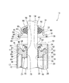
図1に示すように、本実施形態の油圧緩衝器11は、複筒式のもので、例えば自動車のサスペンション装置に用いられるものである。この油圧緩衝器11は、作動流体である油液が封入される略円筒状のシリンダ12と、シリンダ12を覆う略有底円筒状の外筒13と、一部突出する状態でシリンダ12内に挿入される棒状のロッド15と、ロッド15のシリンダ12内に配置される一端に固定されてシリンダ12内を二つの室16,17に画成するピストン18とを有している。
As shown in FIG. 1, the hydraulic shock absorber 11 of the present embodiment is of a double cylinder type, and is used, for example, in an automobile suspension device. The
また、この油圧緩衝器11は、外筒13内のロッド15の突出側とは反対側に配置されるベースバルブ20と、ロッド15の中間部を挿通させてその摺動を案内するロッドガイド21とを有している。ロッドガイド21は、シリンダ12および外筒13の双方のロッド15の突出側の端部に嵌合されている。シリンダ12は、開口する軸方向の一端側がベースバルブ20に嵌合され、開口する軸方向の他端側がロッドガイド21に嵌合されている。
The
外筒13は、シリンダ12より大径であって軸方向両端が開口する略円筒状の外筒本体23と、この外筒本体23のロッド15の突出側とは反対側を閉塞する有底円筒状のベースキャップ24とからなっている。ベースキャップ24は、略円筒状の筒状部25とその軸方向の一端を閉塞する閉塞底部26とを有している。ベースキャップ24は、外筒本体23に対して、閉塞底部26を軸方向の外側に向けた姿勢で筒状部25において嵌合されており、この状態で全周に亘り溶接されて外筒本体23に固定されている。これにより、外筒13は軸方向の一端が閉塞され、軸方向の他端が開口される形状をなす。ベースキャップ24の閉塞底部26の軸方向の外側には、取付アイ27が溶接により固定されている。
The
ベースバルブ20は、ベースキャップ24の筒状部25の内側に配置されて閉塞底部26に当接しており、これにより外筒13に対し径方向および軸方向に位置決めされている。シリンダ12は、上記したように、その軸方向一側の端部にこのベースバルブ20を嵌合させている。これにより、シリンダ12は、ベースバルブ20側の端部が外筒13に対し径方向および軸方向に位置決めされることになる。シリンダ12は、ベースバルブ20とは反対側の端部がロッドガイド21に嵌合されており、これにより、ベースバルブ20とは反対側の端部が外筒13に対し径方向および軸方向に位置決めされている。シリンダ12と外筒13とは同心状に配置されており、これらの間にリザーバ室28が形成されている。
The
シリンダ12および外筒13の端部に設けられたロッドガイド21に、ロッド15が、その一定径の主軸部30において摺動可能に挿通されており、ロッドガイド21はロッド15の摺動を案内する。このロッド15の軸方向の一端に固定されたピストン18が、シリンダ12内に摺動可能に嵌合されることにより、ロッド15は、シリンダ12および外筒13の中心軸線上に配置される。なお、ロッド15のシリンダ12からの突出量が増大して油圧緩衝器11の全長が長くなる伸び行程ではピストン18がシリンダ12内で室16側に摺動することになり、ロッド15のシリンダ12からの突出量が減少して油圧緩衝器11の全長が短くなる縮み行程ではピストン18がシリンダ12内で室17側に摺動することになる。
A
油圧緩衝器11は、ロッドガイド21の軸方向の外側に配置されるキャップ状の閉塞部材31と、閉塞部材31の内側に配置されるパッキン32と、パッキン32の軸方向のロッドガイド21側に当接するパッキンリテーナ33と、パッキンリテーナ33とロッドガイド21との間に介装されるパッキンスプリング34と、閉塞部材31とロッドガイド21と外筒13との間に介装されるシールリング35とを有している。
The hydraulic shock absorber 11 has a cap-
外筒13の外筒本体23は、円筒状の外筒主部38と、外筒主部38におけるロッド15の突出側の端部から径方向内方に突出する係止部39とを有している。係止部39は、いわゆるカール方式と呼ばれる加締め加工により形成されるもので、円筒状の素材の端部を径方向内側に塑性変形させることで形成される。係止部39は、ロッドガイド21の軸方向の外側に当接する閉塞部材31のさらに軸方向の外側に当接してこれを係止する。よって、閉塞部材31は、軸方向の一側がロッドガイド21に当接するロッドガイド当接部40となり、軸方向の他側が外筒13の加締めを受ける加締め受け部41となる。この閉塞部材31は、軸方向の一端が閉塞された外筒13の軸方向他端の開口を閉塞する。
The outer cylinder
パッキン32は、ロッド15と閉塞部材31とに常時接触してこれらとの隙間を閉塞する。パッキンスプリング34は、パッキンリテーナ33をパッキン32の方向に押圧するものであり、閉塞部材31およびパッキンリテーナ33へのパッキン32の押圧力を高める。シールリング35は、閉塞部材31とロッドガイド21とに挟持され、これらと外筒13の内周とに常時接触してこれらとの隙間をシールする。
The
ここで、ロッド15がロッドガイド21を摺動する際に、シリンダ12内の油液がロッド15とロッドガイド21と間で潤滑を行うことになり、このため、シリンダ12内の油液が微量ながらロッドガイド21から漏出する。ロッドガイド21とその閉塞部材31側のパッキン32との隙間はこの油液を溜める油溜め室44となっており、パッキン32は、この油溜め室43の油液が外部に漏出するのを規制する。油溜め室44は、ロッドガイド21に形成された連通路45を介して、外筒13とシリンダ12との間のリザーバ室28に連通しており、油溜め室44に漏出した油液は、連通路45を介してリザーバ室28に排出される。
Here, when the
上記したベースバルブ20は、シリンダ12と外筒13との間のリザーバ室28と、室17との間の油液の流れを制御するもので、室17側の圧力がリザーバ室28側の圧力よりも高い状態で、室17からリザーバ室28側への油液の流れを許容しつつ減衰力を発生させる。また、ベースバルブ20は、室17側の圧力がリザーバ室28側の圧力よりも低い状態で、リザーバ室28から室17側への油液の流れを許容する。
The above-described
つまり、伸び行程で、ロッド15のシリンダ12からの突出量が増大すると、その分の油液がベースバルブ20を介してリザーバ室28から室17に流れることになり、逆に縮み行程でロッド15のシリンダ12への挿入量が増大すると、その分の油液がベースバルブ20を介して室17からリザーバ室28に流れることになる。なお、このような油液の給排に対応するため、リザーバ室28には、下部となるベースキャップ24側に油液が貯留されており、この油液の上側となるロッドガイド21側に油液の量変化を吸収するガスが封入されている。
In other words, when the amount of protrusion of the
ピストン18には、室16と室17との間の油液の流れを制御する減衰力発生機構42が設けられている。減衰力発生機構42は、ピストン18が室17側に移動する縮み行程にて室17側の圧力が室16側の圧力より高くなると、室17から室16側への油液の流れを許容しつつ減衰力を発生させる。また、減衰力発生機構42は、ピストン18が室16側に移動する伸び行程にて、室17側の圧力が室16側の圧力より低くなると、室16から室17側への油液の流れを許容しつつ減衰力を発生させる。
The
図2は、油圧緩衝器11の組み立て途中の状態を示すものであり、図2においては、外筒13が、外筒主部38と、図1に示す係止部39を加工する前の加工前状態部39’とを有している。加工前状態部39’は外筒主部38の加工前状態部39’側の部分と同内径および同外径の円筒状をなしている。
FIG. 2 shows a state during the assembly of the
図2に示すように、ロッドガイド21は、ロッドガイド本体50と、ロッドガイド本体50の内側に嵌合固定されるカラー51とからなっている。ロッドガイド本体50は、金属の一体成形品であり、その外径形状が、軸方向の一側に大径外径部52が形成され、軸方向の他側に大径外径部52よりも小径の小径外径部53が形成された段付き形状をなしている。
As shown in FIG. 2, the
また、ロッドガイド本体50は、その内径形状が、軸方向の一側に小径内径部54が形成され、軸方向の他側に小径内径部54よりも大径の大径内径部55が形成された段付き形状をなしている。大径外径部52、小径外径部53、小径内径部54および大径内径部55は同心状に形成されており、これらの中心軸がロッドガイド本体50の中心軸となる。なお、ロッドガイド21は、大径外径部52において外筒13の外筒主部38の内周部に嵌合し、小径外径部53においてシリンダ12の内周部に嵌合する。
Further, the
ロッドガイド本体50の軸方向の大径外径部52側の端部には、軸方向に凹む環状溝58が、径方向の大径外径部52と小径内径部54との間にこれらと同心状に形成されている。この環状溝58が形成されることにより、ロッドガイド21には、小径内径部54と環状溝58との間に、軸方向に突出する内側環状凸部59が形成されている。また、環状溝58と大径外径部52との間に、軸方向に突出する外側環状凸部60が形成されている。
An
なお、ロッドガイド21の上記した連通路45は、外側環状凸部60の位置に形成されており、ロッドガイド本体50をその軸方向に沿って貫通する。連通路45は、ロッドガイド本体50の周方向に所定の等間隔をあけて複数形成されている。
In addition, the above-mentioned communicating
外側環状凸部60には、連通路45を環状溝58側に開口させる通路溝62がロッドガイド本体50の径方向に沿って形成されている。通路溝62は複数の連通路45のそれぞれに設けられている。シリンダ12内から図1に示す油溜め室44に漏れ出た油液は、油溜め室44から図2に示す通路溝62を介して連通路45に至り、連通路45を介してリザーバ室28に流れるようになっている。
A
ロッドガイド本体50の大径外径部52の外周面は、円筒状をなして外筒13の外筒主部38に嵌合する嵌合円筒面65と、嵌合円筒面65の軸方向における小径外径部53とは反対側の端縁部からロッドガイド本体50の軸直交方向に沿って径方向内側に延出する円環状の平坦面66と、平坦面66の内周側の端縁部から軸方向における嵌合円筒面65とは反対側に、嵌合円筒面65から離れるほど小径となるように延出するテーパ面67とを有している。
The outer peripheral surface of the large-diameter
また、ロッドガイド本体50の大径外径部52の外周面は、嵌合円筒面65の軸方向における小径外径部53側の端縁部からロッドガイド本体50の軸直交方向に沿って径方向内側に延出する円環状の平坦面68と、平坦面68の内周側の端縁部から軸方向における嵌合円筒面65とは反対側に、嵌合円筒面65から離れるほど小径となるように延出するテーパ面69とを有している。これら嵌合円筒面65、平坦面66、テーパ面67、平坦面68およびテーパ面69は同心状に形成されている。
Further, the outer peripheral surface of the large-diameter
なお、ロッドガイド21は、テーパ面67および平坦面66においてシールリング35に当接することになり、ロッドガイド21のこれらを有する部分が、シールリング35が当接するシールリング当接部71となっている。よって、このシールリング当接部71は、テーパ形状の面取部となっている。
The
上記したテーパ面67は、外側環状凸部60に形成されており、このテーパ面67の平坦面66とは反対側から径方向内方に、外側環状凸部60の頂上面75が、ロッドガイド本体50の軸直交方向に略沿って形成されている。
The tapered
カラー51は、円筒状をなしており、フッ素樹脂からなっている。カラー51は、ロッドガイド本体50の大径内径部55に圧入されることでロッドガイド本体50に一体的に固定されてロッドガイド21を構成する。カラー51の内側が、ロッドガイド21の径方向の中央において軸方向に貫通し、ロッド15の一定径の主軸部30を摺接させるように挿通させる挿通穴78となる。
The
パッキンスプリング34は、軸方向一側が小径となり軸方向他側が大径となるテーパ状のコイルスプリングであり、金属からなっている。パッキンスプリング34は、大径側が環状溝58内に入り込み、この大径側の端部を環状溝58の底面に当接させている。
The packing
パッキンリテーナ33は、一定径の円筒状部81と、円筒状部81から離れるほど大径となるように延出するテーパ筒状部82とからなる円環状をなしている。パッキンリテーナ33は、金属板からプレス成形される一体成形品であり、軸方向においてロッドガイド21側に円筒状部81を向けた姿勢で、ロッド15を内側に挿通させる。パッキンリテーナ33は、円筒状部81とテーパ筒状部82との境界位置にパッキンスプリング34の小径側の端部を当接させている。
The packing
シールリング35は、シール性および弾性を有する合成樹脂材料から一体成形されるもので、軸方向に沿う面で断面としたときの片側断面が矩形状をなす汎用性のある角リングとなっている。シールリング35は、自然状態にあるとき、軸方向厚さが一定で、断面幅も一定となっており、軸方向両端の端面84,85が軸直交方向に沿う平坦面となり、外周面86および内周面87は軸方向に沿う。
The
閉塞部材31は、金属板からプレス成形される一体成形品であり、軸方向中間位置に形成された一定径の円筒状部90と、この円筒状部90の軸方向の一端側から径方向外側に延出する有孔円板状のフランジ部91と、円筒状部90の軸方向の他端側から径方向内側に、径方向内側ほど円筒状部90から軸方向に離れるように傾斜して延出するテーパ筒状部92とからなっている。テーパ筒状部92の径方向内側には、軸方向に沿う貫通孔93が形成されている。円筒状部90とフランジ部91とテーパ筒状部92とは同心状に形成されている。閉塞部材31は、フランジ部91をロッドガイド21側に向けた姿勢で、ロッド15を貫通孔93の内側に挿通させる。フランジ部91の軸方向における円筒状部90とは反対側が、上記したロッドガイド当接部40であり、フランジ部91の円筒状部90側が、上記した加締め受け部41となっている。フランジ部91の外径は、自然状態で円形状とされたシールリング35の外径と略同径であり、フランジ部91の内径は、自然状態で円形状とされたシールリング35の内径よりも小径となっている。
The closing
パッキン32は、シール性および弾性を有する合成樹脂材料から一体成形されるもので、円環状をなしている。パッキン32は、外径側に、一定径の円筒面部95と、この円筒面部95の軸方向一端側にあって円筒面部95から離れるほど小径となるテーパ面部96と、円筒面部95の軸方向他端側にあって円筒面部95から離れるほど小径となるテーパ面部97とを有している。また、内径側の内面98は大径部分と小径部分とが交互に配置される段状をなしている。パッキン32は、円筒面部95が閉塞部材31の円筒状部90の内周面に密着可能であり、テーパ面部96が閉塞部材31のテーパ筒状部92の内周面に密着可能となっている。また、テーパ面部97がパッキンリテーナ33のテーパ筒状部82の内周面に密着可能であり、内面98がロッド15の主軸部30に密着可能となっている。
The packing 32 is integrally formed from a synthetic resin material having sealing properties and elasticity, and has an annular shape. The packing 32 has a
そして、油圧緩衝器11を組み立てる場合に、図2に示すように、シールリング35が閉塞部材31に仮止めされた状態で組み付けられることになる。つまり、油圧緩衝器11を製造する製造方法は、シールリング35を閉塞部材31に仮止めする仮止め工程を有している。
When the
「仮止め工程」
この仮止め工程では、図3に示すように、金属製の仮止め用治具105が用いられる。この仮止め用治具105は、円環状をなしており、内径側が、一定径の保持円筒面106と、保持円筒面106の軸方向一側の端部から、保持円筒面106から離れるほど大径となるテーパ状をなして延出する入口テーパ面107と、保持円筒面106の軸方向他側の端部から、その軸直交方向に沿って径方向内方に延出する載置面108と、載置面108の内周縁部から保持円筒面106とは反対側に抜ける一定径の貫通円筒面109とを有している。保持円筒面106は、自然状態で円形とされたシールリング35の外周面86と同等に形成され、保持円筒面106の高さは自然状態のシールリング35の軸方向長さと、閉塞部材31のフランジ部91の軸方向長さとを合わせた長さと同等に形成されている。
"Temporary fixing process"
In this temporary fixing step, as shown in FIG. 3, a metal
そして、仮止め工程においては、手作業あるいは機械により、シールリング35を仮止め用治具105に嵌合させる。このとき、シールリング35を、入口テーパ面107の案内で保持円筒面106に円滑に嵌合させ、その後、保持円筒面106に沿って摺動させて載置面108に載置させる。この状態で、シールリング35は、下側の端面85が全面にわたって載置面108に接触し、また外周面86が保持円筒面106に接触することで全体として円形状に保持される。
In the temporary fixing step, the
上記のようにして仮止め用治具105に載置された状態のシールリング35の上側の端面84に、図4に示す仮止め手段としての接着剤110を手作業あるいは機械により塗布する。このとき、図4(a)に示すように、周方向に間隔をあけた複数カ所にそれぞれ点状に部分的に塗布する。言い換えれば、接着剤110をシールリング35の上側の端面84の周方向の全体に連続的に塗布するのではなく、この周方向に断続的に一部にのみ塗布する。なお、作業者あるいは機械は、複数カ所に部分的に塗布する場合に、シールリング35の周方向に等間隔で接着剤110を塗布することになる。なお、接着剤110を、図4(b)に示すように、上側の端面84の一カ所のみに点状に部分的に塗布しても良いが、シールリング35を閉塞部材31と同心の円形状を維持するように仮止めするためには、複数カ所に塗布するのが良い。
The adhesive 110 as temporary fixing means shown in FIG. 4 is manually or mechanically applied to the
また、このようにシールリング35の上側の端面84に接着剤110を塗布するとき、シールリング35の径方向にも部分的に接着剤110を設けることになる。言い換えれば、接着剤110を、シールリング35の端面84の径方向の全体に連続的に塗布するのではなく、径方向の一部にのみ塗布する。しかも、接着剤110を、端面84の径方向の端部ではなく中間部に塗布することになる。塗布する複数の接着剤110のすべてを同様に径方向の中間部の一部にのみ塗布することになる。なお、接着剤110は速乾性のあるものが用いられている。
Further, when the adhesive 110 is applied to the upper end face 84 of the
このように塗布された接着剤110が固化する前に、手作業あるいは機械により、図3に示すように、閉塞部材31のフランジ部91を仮止め用治具105に挿入する。このとき、フランジ部91は、入口テーパ面107の案内で保持円筒面106に円滑に嵌合し、その後、保持円筒面106に沿って摺動してシールリング35に当接する。このとき、フランジ部91は、下側のロッドガイド当接部40がシールリング35の上側の端面84に同心状に位置決めされた状態で接触する。その際に、フランジ部91は、シールリング35の上側の端面84に塗布されていた接着剤110にも接触し、よって接着剤110を介してシールリング35に接着される。この接着状態でも、接着剤110は、上記のように閉塞部材31の周方向に部分的に存在する状態が維持されることになる。このようにして、シールリング35が、閉塞部材31に対し、同心状に配置された状態(つまりセンタリングされた状態)で接着剤110により接着されて仮止めされる。
Before the adhesive 110 applied in this way is solidified, the
接着剤110によりシールリング35と閉塞部材31とが接着されるのに必要な所定時間が経過すると、手作業あるいは機械により、閉塞部材31を、仮止め用治具105よりも上方に位置するテーパ筒状部92において仮止め用治具105から上方に引き抜く。すると、シールリング35も閉塞部材31とともに仮止め用治具105から上方に引き抜かれる。以上により、シールリング35を、閉塞部材31に接着剤110によって仮止めする仮止め工程が終了する。なお、閉塞部材31に仮止めされたシールリング35においては、軸方向の閉塞部材31側、つまり端面84側のみが拘束され、閉塞部材31とは反対側(言い換えれば組み込み後のシリンダ12側)の端部、つまり端面85側は自由端となっている。
When a predetermined time necessary for bonding the
なお、上記においては、シールリング35の外径と閉塞部材31のフランジ部91の外径とが略同径であるため、これらを同心状に仮止めするための仮止め用治具105に、これらの軸方向長さ分の軸方向長さを有する保持円筒面106が設けられている。しかしながら、シールリング35の外径とフランジ部35の外径とが異なる大きさの場合には、仮止め用治具105に、シールリング35の外径および軸方向長さに合う内径および軸方向長の保持円筒面が下側に設けられ、この保持円筒面と同心状をなして、フランジ部91の外径および軸方向長さに合う内径および軸方向長さの保持円筒面が上側に設けられることになる。つまり、保持円筒面が同心の段付き形状となる。
In the above, since the outer diameter of the
「挿入工程」
外筒13内に、図1に示すベースバルブ20、シリンダ12、ピストン18、ロッド15、ロッドガイド21、パッキンスプリング34およびパッキンリテーナ33が組み付けられた状態から、手作業または機械により、シールリングおよび閉塞部材31を、図2に示すように、一体に外筒13の内に加工前状態部39’側から挿入する挿入工程を行う。このとき、先行してパッキン32がロッド15に嵌合されており、パッキン32はこれを覆うように設けられる閉塞部材31で押圧されてパッキンリテーナ33側に押し込まれることになる。
"Insertion process"
From the state in which the
そして、この挿入工程において、閉塞部材31が加工前状態部39’内を摺動することになり、これに仮止めされたシールリング35も外周面86が加工前状態部39’内を摺動することになる。この閉塞部材31の加工前状態部39’による案内により、閉塞部材31に同心状に仮止めされたシールリング35が、ロッドガイド21のシールリング当接部71と外筒13との間の円環状の隙間111の上側にこれと同心状に配置される。
In this insertion step, the closing
なお、テーパ面67はその最小径が閉塞部材31に仮止めされた状態のシールリング35の内径よりも小径となっており、その最大径が閉塞部材31に仮止めされた状態のシールリング35の内径よりも大径となっている。さらに、テーパ面67はその軸方向長さがシールリング35の軸方向長さと同等になっている。
The tapered
「セット工程」
閉塞部材31を、上記の挿入工程に引き続いて、手作業または機械により、外筒主部38の内側を摺動させながら、ロッドガイド21側に移動させるセット工程が行われる。このセット工程では、シールリング35をロッドガイド21と閉塞部材31との間に挟持しつつ外筒13の内周に接触させるとともに、閉塞部材31のロッドガイド当接部40をロッドガイド21の外側環状凸部60の頂上面75に当接させることになる。
"Set process"
Subsequent to the above insertion step, a setting step is performed in which the closing
このセット工程によって、シールリング35が、外筒主部38と、ロッドガイド21のシールリング当接部71との間の先細の空間111に押し込まれることになる。このとき、シールリング35は、内周面87の端面85側がシールリング当接部71のテーパ面67の拡径により拡径される一方、外周面86は外筒主部38で拡径が規制されることになるため、端面85側ほど径方向に潰れることになってテーパ面67および外筒主部38の内周面に密着する。つまり、テーパ面67への嵌合によるくさび効果で、閉塞部材31に対し自由端であるシールリング35の端面85側が弾性変形してテーパ面67および外筒主部38の内周面に密着する。そして、閉塞部材31のフランジ部91のロッドガイド当接部40をロッドガイド21の外側環状凸部60の頂上面76に当接させると、セット工程が終了する。
By this setting process, the
「加締め工程」
上記セット工程の後、機械により、カール方式で、外筒13の加工前状態部39’を径方向内側に折り曲げて閉塞部材31のフランジ部91の加締め受け部41に向け加締めて係止部39を形成する加締め工程を行う。これにより、閉塞部材31のフランジ部91が、そのロッドガイド当接部40をロッドガイド21に、加締め受け部41を係止部39に、それぞれ当接させて、これらに挟持される状態になる。つまり、外筒13、閉塞部材31およびロッドガイド21が一体的に固定されることになる。このとき、シールリング35は、セット工程の状態、つまり上記した隙間111に入り込んで外筒13の内周に接触しつつロッドガイド21と閉塞部材31との間に挟持される状態に維持される。
"Casting process"
After the above setting process, the machined
上記した特許文献1に記載のシリンダ装置では、シールリングが他のリング部材に一体化されており、外筒への組み付けが容易となっている。しかしながら、シールリングが他のリング部材に一体化されているため、部品製造コストが増大してしまう。また、上記した特許文献2に記載のシリンダ装置は、キャップ体で外筒の端部を閉塞するものであってシリンダとキャップ体とを溶接等で閉塞する必要がある。さらに、シールリングをリング部材などと一体化することなく、単独で組み付けられる構造であり、組み付けの作業性が良くないという問題があり、溶接を行うことによる生産性、信頼性の確保の難しさがあった。また、組み付けの作業性の向上が望まれていた。 In the cylinder device described in Patent Document 1 described above, the seal ring is integrated with another ring member, and the assembly to the outer cylinder is easy. However, since the seal ring is integrated with another ring member, the part manufacturing cost increases. Moreover, the cylinder device described in Patent Document 2 described above closes the end of the outer cylinder with a cap body, and needs to close the cylinder and the cap body by welding or the like. Furthermore, it is a structure that can be assembled independently without integrating the seal ring with a ring member, etc., and there is a problem that the workability of the assembly is not good, and it is difficult to ensure productivity and reliability by welding. was there. In addition, improvement in workability of assembly has been desired.
これに対し、以上に述べた第1実施形態によれば、シールリング35と閉塞部材31とを別部品とすることで、部品製造コストを抑え、その上で、シールリング35を、閉塞部材31に仮止め手段である接着剤110によって仮止めすることで、組み付けの作業性を向上させることができる。したがって、単独のシールリング35を用いる場合であっても、組み付けの作業性を向上させることができる。しかも、単独のシールリング35を用いる場合であっても、これをロッドガイド21のシールリング当接部71と外筒13との間の隙間111に正確かつ確実に入り込ませることができる。なお、ロッドガイド21のシールリング当接部71と外筒13との間の隙間111を狙って外側から単独でシールリング35を配置する場合には、シールリング35を隙間111に正確かつ確実に入り込ませるためには、手作業で慎重にシールリング35を全周にわたって隙間55に配置する煩雑な作業が必要になるが、これと比べても、特別に慎重な作業が必要なくなることから、組み付けの作業性を向上させることができる。
On the other hand, according to the first embodiment described above, the
また、仮止め手段である接着剤110が、閉塞部材31の周方向に部分的に設けられるため、仮止めのためのコスト増を抑制することができる。
Moreover, since the adhesive 110 which is temporary fixing means is partially provided in the circumferential direction of the closing
さらに、仮止め手段が接着剤110であり、シールリング35が閉塞部材31に接着剤110により接着されて仮止めされるため、低コストで容易かつ確実に仮止めすることができる。
Furthermore, since the temporary fixing means is the adhesive 110 and the
加えて、接着剤110が、シールリング35の径方向に部分的に設けられ、外周面86および内周面87から離間しているため、接着剤110のシールリング35から径方向へのはみ出しを抑制し、乾燥を早めることができる。よって、仮止め工程の品質を向上でき、仮止め工程に要する時間を短縮することができる。つまり、径方向に亘って全範囲に接着剤を塗布すると、速乾性に優れた接着剤は、硬いので薄く塗れず、仮止め時にシールリング35から径方向にはみ出てしまうことになり好ましくない。なお、軟らかい接着剤は乾燥に時間を要するので、仮止め用としては不向きである。
In addition, since the adhesive 110 is partially provided in the radial direction of the
また、ロッドガイド21のシールリング35が当接するシールリング当接部71は、テーパ形状の面取部であるため、くさび効果でシール性を高めることができる。
Further, since the seal
さらに、シールリング35は、シリンダ12側の端部を自由端としたため、テーパ形状の面取部であるシールリング当接部71によって確実なくさび効果が得られることになり、よって、シール性をさらに高めることができる。
Furthermore, since the
「第2実施形態」
次に、第2実施形態を主に図5および図6に基づいて第1実施形態との相違部分を中心に説明する。なお、第1実施形態と共通する部位については、同一称呼、同一の符号で表す。
“Second Embodiment”
Next, the second embodiment will be described mainly based on FIGS. 5 and 6 with a focus on differences from the first embodiment. In addition, about the site | part which is common in 1st Embodiment, it represents with the same name and the same code | symbol.
第2実施形態においては、第1実施形態のように閉塞部材31にシールリング35を仮止めするのではなく、ロッドガイド21に上記とは異なるシールリング35Aを仮止めする構造になっている。
In the second embodiment, the
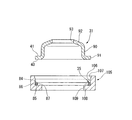
シールリング35Aは、弾性を有する合成樹脂材料から一体成形されるもので、第1実施形態のシールリング35と同形状のシールリング本体部121を有している。つまり、シールリング本体部121は、軸方向に沿う面で断面としたときの片側断面が矩形状をなす角リング形状となっており、自然状態にあるとき、軸方向厚さが一定で、断面幅も一定となっていて、軸方向両端の端面84,85が軸直交方向に沿い、外周面86および内周面87が軸方向に沿っている。
The
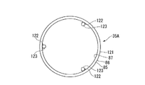
そして、シールリング35Aには、シールリング本体部121の端面84側から径方向内方に延出する板状の延出板部122が複数、具体的には図6に示すように三カ所、周方向に等間隔で形成されている。これらの延出板部122は、図5に示すように、シールリング本体部121の端面84と同一面から、シールリング本体部121の軸方向長さよりも薄い厚さで延出している。
The
加えて、各延出板部122のシールリング本体部121とは反対側には、シールリング本体部121の軸方向にてシールリング本体部121と同側にシールリング本体部121よりも長く延出する仮止め手段としての嵌合部123がそれぞれ形成されている。これらの嵌合部123は、延出板部122とは反対の先端部が面取りされた円柱状をなしている。
In addition, on the opposite side of each extending
ロッドガイド21を軸方向に貫通する連通路45は丸穴であり、ロッドガイド21の周方向に等間隔で上記した嵌合部123よりも多い数(具体的には2倍の6カ所)形成されている。これら複数の連通路45の配設円と、シールリング35Aの嵌合部123の配設円とは一致している。また、嵌合部123は、連通路45よりも若干大径に形成されている。これにより、ロッドガイド21の複数の連通路45のうちの一部に複数の嵌合部123が嵌合可能となっている。よって、嵌合部123が嵌合されない残りの連通路45で油溜め室44をリザーバ室28に連通させる。なお、嵌合部123の軸方向長さは、連通路45の軸方向長さよりも短くなっている。
The
そして、第2実施形態では、油圧緩衝器11を組み立てる場合に、シールリング35Aがロッドガイド21に仮止めされた状態で組み付けられることになる。つまり、油圧緩衝器11を製造する製造方法が、シールリング35Aをロッドガイド21に仮止めする仮止め工程を有している。
In the second embodiment, when the
「仮止め工程」
この仮止め工程では、手作業あるいは機械による圧入により、シールリング35Aのすべての嵌合部123を、ロッドガイド21の対応する連通路45に、軸方向の外側環状凸部60側から嵌合させる。これにより、シールリング35Aは、シールリング本体部121がロッドガイド21の軸方向の外側環状凸部60側に当接する状態で、ロッドガイド21に仮止めされることになる。このとき、シールリング本体部121をロッドガイド21の軸方向の外側環状凸部60側に当接させるものの、ほぼ変形させない範囲内で、嵌合部123が連通路45に圧入される。よって、この状態では、嵌合部123の軸方向における延出板部122とは反対側の一部のみが連通路45に嵌合している。
"Temporary fixing process"
In this temporary fixing step, all the
以上のようにして、シールリング35Aは、その周方向に間隔をあけた複数カ所にそれぞれ部分的に設けられた仮止手段としての嵌合部123でロッドガイド21に仮止めされる。言い換えれば、嵌合部123はシールリング35Aの周方向の全体に形成されているのではなく、この周方向に断続的に一部にのみ形成されている。そして、仮止めされた状態で、シールリング35Aは、シールリング本体部121が円形状に保持されてシールリング当接部71と略同径の同心状をなす。なお、嵌合部123を一カ所のみに部分的に形成しても良いが、シールリング35Aをロッドガイド21に同心の円形状で一体化させるためには、複数カ所に設けるのが良く、配置は等間隔が良い。
As described above, the
以上により、シールリング35Aを、ロッドガイド21に嵌合部123によって仮止めする仮止め工程が終了する。なお、ロッドガイド21に仮止めされたシールリング35Aにおいては、シールリング本体部121が、嵌合部123および延出板部122によって軸方向のロッドガイド21とは反対側のみが拘束され、ロッドガイド21側(言い換えれば組み込み後のシリンダ12側)の端部、つまり端面85側が自由端となっている。
Thus, the temporary fixing process of temporarily fixing the
「挿入工程」
外筒13内に、図1に示すベースバルブ20、シリンダ12、ピストン18およびロッド15が組み込まれた状態から、手作業または機械により、シールリング35Aおよびロッドガイド21を、図5に示すように、一体に外筒13の内に加工前状態部39’側から、小径外径部53をシリンダ12内に嵌合させる位置まで挿入する挿入工程を行う。このとき、ロッドガイド21は、大径外径部52の嵌合円筒面65において加工前状態部39’および外筒主部38の内周面を摺動することになり、これに仮止めされたシールリング35Aも、シールリング本体部121の外周面86が、加工前状態部39’および外筒主部38の内周面を摺動することになる。この挿入工程が完了すると、シールリング35Aは、ロッドガイド21のシールリング当接部71と外筒13との間の円環状の隙間111の上側にこれと同心状に配置される状態になる。この挿入工程の後、パッキンスプリング34およびパッキンリテーナ33がロッドガイド21上に配置される。
"Insertion process"
From the state in which the
「セット工程」
上記挿入工程の後、手作業または機械により、閉塞部材31を、加工前状態部39’および外筒主部38の内側を摺動させながら、ロッドガイド21側に移動させるセット工程を行う。このセット工程により、閉塞部材31が、ロッドガイド21に仮止めされたシールリング35Aをロッドガイド21側に押圧する。このセット工程において、パッキン32もロッド15に設けられて閉塞部材31とともに押し込まれることになる。
"Set process"
After the inserting step, a setting step is performed in which the closing
このセット工程によって、嵌合部123の軸方向における延出板部122側のそれまで嵌合していなかった部分が連通路45に押し込まれるとともに、シールリング35Aのシールリング本体部121が、外筒主部38と、ロッドガイド21のシールリング当接部71のテーパ面67および平坦面66との間の先細の空間111に良好に押し込まれることになる。これにより、シールリング本体部121を閉塞部材31とロッドガイド21との間に挟持しつつ外筒13の内周に接触させる状態となる。
By this setting step, the portion of the
このときも、シールリング本体部121は、内周面87の端面85側がテーパ面67の拡径により拡径される一方、外周面86は一定径の外筒主部38で拡径が規制されることになるため、端面85側が径方向に潰れることになってテーパ面67および外筒主部38の内周面に密着する。つまり、テーパ面67への嵌合によるくさび効果で、閉塞部材31に対し自由端となるシールリング本体部121の端面85側がテーパ面67および外筒主部38の内周面に密着する。そして、閉塞部材31のフランジ部91のロッドガイド当接部40がロッドガイド21の外側環状凸部60の頂上面76に当接すると、セット工程が終了する。
Also at this time, the
「加締め工程」
上記セット工程の後、カール方式で、機械により、外筒13の加工前状態部39’を径方向内側に折り曲げて閉塞部材31のフランジ部91の加締め受け部41に向け加締めて係止部39を形成する加締め工程を行う。これにより、閉塞部材31のフランジ部91は、ロッドガイド当接部40をロッドガイド21に、加締め受け部41を係止部39にそれぞれ当接させて、これらに挟持され、固定される状態になる。この状態で、シールリング35Aのシールリング本体部121は、上記したセット工程での状態、つまり隙間111に入り込んで外筒13の内周に接触しつつロッドガイド21と閉塞部材31との間に挟持される状態が維持される。この加締め工程が終了することにより、外筒13内への上記各部品の組み込みが終了する。
"Casting process"
After the setting step, by a curl method, the machined
以上に述べた第2実施形態によれば、シールリング35Aと閉塞部材31とを別部品とすることで、溶接等で隙間を閉塞する必要を排除しつつ部品製造コストを抑え、その上で、シールリング35Aを、ロッドガイド21に嵌合部123によって仮止めすることで、組み付けの作業性を向上させることができる。したがって、単独のシールリング35Aを用いる場合であっても、組み付けの作業性を向上させることができる。しかも、単独のシールリング35Aを用いる場合であっても、これをロッドガイド21のシールリング当接部71と外筒13との間の隙間111に正確かつ確実に入り込ませることができる。
According to the second embodiment described above, by making the
また、仮止め手段である嵌合部123が、ロッドガイド21の周方向に部分的に設けられるため、仮止めのためのコスト増および重量増を抑制することができる。
Moreover, since the
さらに、シールリング35Aに、仮止め手段として、ロッドガイド21の連通路45に嵌合する嵌合部123を形成するため、シールリング35Aをロッドガイド21に確実に仮止めすることができる。しかも、嵌合部123を複数の連通路45のうちの一部に嵌合させるため、油溜め室44の油液をリザーバ室28に良好に戻すことができる。
Further, since the
「第3実施形態」
次に、第3実施形態を主に図7に基づいて第2実施形態との相違部分を中心に説明する。なお、第2実施形態と共通する部位については、同一称呼、同一の符号で表す。
“Third Embodiment”
Next, the third embodiment will be described mainly on the basis of FIG. 7 with a focus on differences from the second embodiment. In addition, about the site | part which is common in 2nd Embodiment, it represents with the same name and the same code | symbol.
第3実施形態においては、第2実施形態とは異なるシールリング35Bが用いられている。このシールリング35Bは、第2実施形態のシールリング35Aに対して異なる嵌合部126が設けられており、嵌合部126以外(シールリング本体部121および延出板部122)はシールリング35Aと同様になっている。
In the third embodiment, a
シールリング35Bにおいても、径方向における各延出板部122のシールリング本体部121とは反対側に、シールリング本体部121の軸方向にてシールリング本体部121と同側にシールリング本体部121よりも長く延出する仮止め手段としての嵌合部126がそれぞれ形成されている。
Also in the
嵌合部126は、円柱状の嵌合軸部127を有しており、この嵌合軸部127の軸方向の中間部に凹部128が形成されている。凹部128は、嵌合軸部127に対し、シールリング本体部121の径方向において外側から内側に向けて形成されており、シールリング本体部121の周方向に貫通している。また、凹部128は、嵌合軸部127の軸方向において延出板部122とは反対側に偏って形成されており、嵌合部126には、凹部128の延出板部122とは反対側に、シールリング本体部121の径方向の外側に向け突出する係止足部129が形成されている。この係止足部129は、嵌合軸部127とで嵌合部126を構成するもので、嵌合軸部127の軸方向における厚さが短い薄板状をなしており、シールリング本体部121の径方向において嵌合軸部127よりも外側に突出している。
The
なお、複数の連通路45の配設円と、シールリング35Bの複数の嵌合軸部127の配設円とは一致している。また、嵌合軸部127の外径は連通路45の内径よりも若干小径となっており、嵌合軸部127は連通溝45にルーズな状態で嵌合される。また、嵌合部126の軸方向長さは、連通路45の軸方向長さよりも長くなっている。嵌合部126の連通路45への嵌合時に、係止足部129は、連通溝45に接触することで凹部128側に折れ曲がって凹部128内に収まり、嵌合部126の連通溝45への嵌合を阻害しないようになっている。係止足部129は、連通溝45から突出する位置で連通溝45への接触が解除されることで、弾性により戻り、ロッドガイド21に係止される状態になる。
The arrangement circle of the plurality of
そして、第3実施形態においても、油圧緩衝器11を組み立てる場合に、シールリング35Bがロッドガイド21に仮止めされた状態で組み付けられることになる。つまり、油圧緩衝器11を製造する製造方法が、シールリング35Bをロッドガイド21に仮止めする仮止め工程を有している。
Also in the third embodiment, when assembling the
「仮止め工程」
この仮止め工程では、手作業あるいは機械により、シールリング35Bのすべての嵌合部126を、ロッドガイド21の連通路45に、軸方向の外側環状凸部60側から嵌合させる。このとき、嵌合部126は、係止足部129が連通路45から外側環状凸部60とは反対側に突出するまで嵌合させられる。この状態で、シールリング35Bは、係止足部129がロッドガイド21の軸方向の外側環状凸部60とは反対側に係止され、シールリング本体部121がロッドガイド21の軸方向の外側環状凸部60側に当接する結果、ロッドガイド21に仮止めされることになる。この仮止め状態で、シールリング本体部121が第2実施形態と同様、円形状に保持されてシールリング当接部71と略同径の同心状をなす。このとき、シールリング本体部121は、ロッドガイド21の外側環状凸部60側に当接するもののほぼ変形はしない。
"Temporary fixing process"
In this temporary fixing step, all the
「挿入工程」および「加締め工程」は、第2実施形態と同様である。また、これらの間に行われる「セット工程」も、以下の点を除いて同様である。 The “insertion step” and “caulking step” are the same as in the second embodiment. The “setting step” performed between them is the same except for the following points.
セット工程にて、閉塞部材31を、加工前状態部39’および外筒主部38の内側を摺動させながら、ロッドガイド21側に移動させると、閉塞部材31は、ロッドガイド21に仮止めされたシールリング35Bをロッドガイド21側に押圧することになる。その際に、閉塞部材31は、嵌合部126の延出板部122側のそれまで挿入されていなかった部分を連通路45に挿入させながら、シールリング35Bのシールリング本体部121を、外筒主部38とロッドガイド21のシールリング当接部71との間の空間111に押し込むことになる。
When the closing
第1実施形態においては、シールリング35を接着剤110により閉塞部材31に仮止めする場合を、第2実施形態においては、シールリング35Aをシールリング35Aに形成された嵌合部123によりロッドガイド21に仮止めする場合を、第3実施形態においては、シールリング35Bをシールリング35Bに形成された嵌合部126によりロッドガイド21に仮止めする場合をそれぞれ説明したが、逆に、シールリングをロッドガイドに接着剤により仮止めしたり、シールリングをこれに形成された嵌合部により閉塞部材に仮止めしても良い。
In the first embodiment, the
また、仮止め手段として、接着剤ではなく、加硫接着や焼き付けにより、シールリングを閉塞部材31またはロッドガイド21に接着しても良い。この場合も、第1実施形態と同様に全周ではなく周方向に部分的に接着するのが良い。
Further, as a temporary fixing means, the seal ring may be bonded to the closing
また、仮止め手段として、接着剤にかえグリス等の粘着剤を用いてシールリング35を閉塞部材31に仮止めしたり、ロッドガイド21に仮止めしたりすることも可能である。この場合は、より仮止めを確実にするため、仮止め手段としてのグリスを閉塞部材31またはロッドガイド21の周方向の全周に亘ってシールリング35に塗布するのが良い。なお、このように塗布された仮止め手段としてのグリスは、シールリング35を、これが仮止めされた閉塞部材31またはロッドガイド21から容易に分離可能となるように仮止めすることになる。これにより、シールリング35を、分離不可となるように、これが仮止めされた閉塞部材31またはロッドガイド21に、全周あるいは一部について接着する場合とは異なり、仮止め後に必要に応じてシールリング35を分離することができる。
Further, as a temporary fixing means, it is possible to temporarily fix the
また、第1実施形態においては、シールリング35が角リングである場合を例にとり説明したが、径方向の片側断面が円形状のOリングにも適用可能である。
また、第2,第3実施形態においては、シールリング本体部121が角リング状をなす場合を例にとり説明したが、径方向の片側断面が延出板部122とは反対側に突出する半円状とされる場合にも適用可能である。
また、上記キャップ状の閉塞部材31にかえて、上記した特許文献1に示す円環状の板材を用いる場合にも適用可能である。
In the first embodiment, the case where the
Further, in the second and third embodiments, the case where the seal ring
Moreover, it is applicable also when using the annular | circular shaped board | plate material shown to above-mentioned patent document 1 instead of the said cap-shaped
以上に述べた実施形態によれば、作動流体が封入されるシリンダと、該シリンダを覆い、一端が閉塞され、他端が開口される外筒と、前記シリンダに挿入されるロッドと、前記シリンダおよび前記外筒の端部に設けられて前記ロッドを案内するロッドガイドと、前記外筒の他端開口を閉塞する環状の閉塞部材と、前記ロッドガイドと前記閉塞部材との間に挟持され前記外筒の内周と接触するシールリングと、を備え、前記閉塞部材は、一側が前記ロッドガイドに当接するロッドガイド当接部であって、他側が前記外筒の加締めを受ける加締め受け部となり、前記シールリングは、前記閉塞部材または前記ロッドガイドに仮止め手段によって仮止めされる構成とした。これにより、シールリングと閉塞部材とを別部品とすることで、溶接等で隙間を閉塞する必要を排除しつつ部品製造コストを抑え、その上で、シールリングを、閉塞部材に仮止め手段によって仮止めすることで、組み付けの作業性を向上させることができる。したがって、単独のシールリングを用いる場合であっても、組み付けの作業性を向上させることができる。 According to the embodiment described above, the cylinder in which the working fluid is sealed, the outer cylinder that covers the cylinder and is closed at one end and opened at the other end, the rod inserted into the cylinder, and the cylinder And a rod guide provided at an end of the outer cylinder for guiding the rod, an annular closing member for closing the other end opening of the outer cylinder, and sandwiched between the rod guide and the closing member. A seal ring that comes into contact with the inner periphery of the outer cylinder, wherein the closing member is a rod guide abutting portion that abuts the rod guide on one side, and a caulking receiver that receives the caulking of the outer cylinder on the other side The seal ring is temporarily fixed to the closing member or the rod guide by temporary fixing means. Thereby, by making the seal ring and the closing member as separate parts, it is possible to reduce the manufacturing cost of the parts while eliminating the need to close the gap by welding or the like. By temporarily fixing, assembly workability can be improved. Therefore, even when a single seal ring is used, the workability of assembly can be improved.
また、前記仮止め手段は、前記閉塞部材または前記ロッドガイドの周方向に部分的に設けられる構成とした。これにより、仮止めのためのコスト増を抑制することができる。 Further, the temporary fixing means is configured to be partially provided in the circumferential direction of the closing member or the rod guide. Thereby, the cost increase for temporary fixing can be suppressed.
また、前記仮止め手段は、前記閉塞部材または前記ロッドガイドの周方向の全周に亘って設けられ、前記シールリングをこれが仮止めされた前記閉塞部材または前記ロッドガイドから分離可能である構成とした。これにより、確実に仮止めでき、仮止め後に必要に応じてシールリングを分離することができる。 The temporary fixing means is provided over the entire circumference of the closing member or the rod guide, and the seal ring is separable from the closing member or the rod guide to which the sealing ring is temporarily fixed. did. Thereby, it can be surely temporarily fixed and the seal ring can be separated if necessary after temporary fixing.
また、前記仮止め手段は接着剤であり、前記シールリングは前記閉塞部材に前記接着剤により接着されて仮止めされる構成とした。これにより、低コストで容易かつ確実に仮止めすることができる。 The temporary fixing means is an adhesive, and the seal ring is temporarily fixed by being bonded to the closing member by the adhesive. As a result, the temporary fixing can be easily and reliably performed at low cost.
また、前記接着剤は、前記シールリングの径方向に部分的に設けられる構成とした。これにより、接着剤のはみ出しを抑制し、乾燥を早めることができる。よって、仮止め工程の品質を向上でき、仮止め工程に要する時間を短縮することができる。 Further, the adhesive is configured to be partially provided in the radial direction of the seal ring. Thereby, the protrusion of an adhesive agent can be suppressed and drying can be accelerated. Therefore, the quality of the temporary fixing process can be improved, and the time required for the temporary fixing process can be shortened.
また、前記ロッドガイドの前記閉塞部材側には、油溜め室が形成され、前記ロッドガイドに、前記油溜め室と、前記シリンダと前記外筒とで形成されるリザーバ室とを連通する連通路を設け、前記仮止め手段は、前記シールリングに形成されて前記連通路に嵌合する嵌合部であり、前記嵌合部を前記連通路の一部に嵌合させる構成とした。これにより、シールリングをロッドガイドに確実に仮止めすることができる。しかも、嵌合部を連通路の一部に嵌合させるため、残りの部分で油溜め室の油液をリザーバ室に良好に戻すことができる。 In addition, an oil reservoir chamber is formed on the rod guide side of the rod guide, and a communication passage that communicates the rod guide with the oil reservoir chamber and a reservoir chamber formed by the cylinder and the outer cylinder. The temporary fixing means is a fitting part that is formed on the seal ring and fits into the communication path, and the fitting part is fitted into a part of the communication path. Thereby, the seal ring can be securely temporarily fixed to the rod guide. In addition, since the fitting portion is fitted to a part of the communication path, the oil in the oil sump chamber can be satisfactorily returned to the reservoir chamber at the remaining portion.
また、前記ロッドガイドの前記シールリングが当接するシールリング当接部は、テーパ形状の面取部である構成とした。これにより、くさび効果でシール性を高めることができる。 Further, the seal ring abutting portion with which the seal ring of the rod guide abuts is a tapered chamfered portion. Thereby, sealing performance can be improved by the wedge effect.
また、前記シールリングは、前記シリンダ側の端部を自由端とした。これにより、テーパ形状の面取部によって確実なくさび効果が得られることになり、よって、シール性をさらに高めることができる。 The seal ring has a free end at the end on the cylinder side. Thereby, the taper-shaped chamfered portion can surely obtain the rust effect, so that the sealing performance can be further enhanced.
また、作動流体が封入されるシリンダと、該シリンダを覆い、一端が閉塞され、他端が開口される外筒と、前記シリンダに挿入されるロッドと、前記シリンダおよび前記外筒の端部に設けられて前記ロッドを案内するロッドガイドと、前記外筒の他端開口を閉塞する環状の閉塞部材と、前記ロッドガイドと前記閉塞部材との間に挟持され前記外筒の内周と接触するシールリングと、を備え、前記閉塞部材は、一側が前記ロッドガイドに当接するロッドガイド当接部であって、他側が前記外筒の加締めを受ける加締め受け部となるシリンダ装置の製造方法であって、前記シールリングを、前記閉塞部材または前記ロッドガイドに仮止め手段によって仮止めする仮止め工程と、前記シールリングとこれが仮止めされた前記閉塞部材または前記ロッドガイドとを一体に前記外筒内に挿入する挿入工程と、前記シールリングを前記ロッドガイドと前記閉塞部材との間に挟持し前記外筒の内周と接触させつつ前記閉塞部材の前記ロッドガイド当接部を前記ロッドガイドに当接させるセット工程と、前記外筒を前記閉塞部材の前記加締め受け部に向け加締める加締め工程と、を有する構成とした。これにより、シールリングと閉塞部材とを別部品とすることで、溶接等で隙間を閉塞する必要を排除しつつ部品製造コストを抑え、その上で、シールリングを、閉塞部材に仮止め手段によって仮止めすることで、組み付けの作業性を向上させることができる。したがって、単独のシールリングを用いる場合であっても、組み付けの作業性を向上させることができる。 In addition, a cylinder in which the working fluid is sealed, an outer cylinder that covers the cylinder, is closed at one end and is opened at the other end, a rod that is inserted into the cylinder, and ends of the cylinder and the outer cylinder A rod guide provided to guide the rod, an annular closing member that closes the other end opening of the outer cylinder, and an inner periphery of the outer cylinder that is sandwiched between the rod guide and the closing member A sealing ring, wherein the closing member is a rod guide abutting portion that contacts one side of the rod guide, and the other side is a caulking receiving portion that receives the caulking of the outer cylinder. A temporary fixing step of temporarily fixing the seal ring to the closing member or the rod guide by temporary fixing means; and the sealing ring and the closing member or the lock to which the seal ring is temporarily fixed. An insertion step of inserting a guide integrally into the outer cylinder, and the rod guide of the closing member while holding the seal ring between the rod guide and the closing member and contacting the inner periphery of the outer cylinder A setting step of bringing the abutting portion into contact with the rod guide and a caulking step of caulking the outer cylinder toward the caulking receiving portion of the closing member are provided. Thereby, by making the seal ring and the closing member as separate parts, it is possible to reduce the manufacturing cost of the parts while eliminating the need to close the gap by welding or the like. By temporarily fixing, assembly workability can be improved. Therefore, even when a single seal ring is used, the workability of assembly can be improved.
11 油圧緩衝器(シリンダ装置)
12 シリンダ
13 外筒
15 ロッド
21 ロッドガイド
28 リザーバ室
31 閉塞部材
35 シールリング
40 ロッドガイド当接部
41 加締め受け部
44 油溜め室
45 連通路
71 シールリング当接部
110 接着剤(仮止め手段)
123 嵌合部(仮止め手段)
11 Hydraulic shock absorber (cylinder device)
DESCRIPTION OF
123 Fitting part (temporary fixing means)
Claims (9)
該シリンダを覆い、一端が閉塞され、他端が開口される外筒と、
前記シリンダに挿入されるロッドと、
前記シリンダおよび前記外筒の端部に設けられて前記ロッドを案内するロッドガイドと、
前記外筒の他端開口を閉塞する環状の閉塞部材と、
前記ロッドガイドと前記閉塞部材との間に挟持され前記外筒の内周と接触するシールリングと、を備え、
前記閉塞部材は、
一側が前記ロッドガイドに当接するロッドガイド当接部であって、
他側が前記外筒の加締めを受ける加締め受け部となり、
前記シールリングは、前記閉塞部材または前記ロッドガイドに仮止め手段によって仮止めされることを特徴とするシリンダ装置。 A cylinder filled with a working fluid;
An outer cylinder covering the cylinder, closed at one end and opened at the other end;
A rod inserted into the cylinder;
A rod guide that is provided at an end of the cylinder and the outer cylinder and guides the rod;
An annular closing member that closes the other end opening of the outer cylinder;
A seal ring sandwiched between the rod guide and the closing member and in contact with the inner periphery of the outer cylinder,
The closing member is
One side is a rod guide contact portion that contacts the rod guide,
The other side becomes a caulking receiving portion that receives caulking of the outer cylinder,
The cylinder device according to claim 1, wherein the seal ring is temporarily fixed to the closing member or the rod guide by temporary fixing means.
前記ロッドガイドに、前記油溜め室と、前記シリンダと前記外筒とで形成されるリザーバ室とを連通する連通路を設け、
前記仮止め手段は、前記シールリングに形成されて前記連通路に嵌合する嵌合部であり、
前記嵌合部を前記連通路の一部に嵌合させることを特徴とする請求項1に記載のシリンダ装置。 An oil sump chamber is formed on the rod guide side of the rod guide,
The rod guide is provided with a communication passage that communicates the oil reservoir chamber and a reservoir chamber formed by the cylinder and the outer cylinder,
The temporary fixing means is a fitting portion that is formed on the seal ring and fits into the communication path,
The cylinder device according to claim 1, wherein the fitting portion is fitted into a part of the communication path.
該シリンダを覆い、一端が閉塞され、他端が開口される外筒と、
前記シリンダに挿入されるロッドと、
前記シリンダおよび前記外筒の端部に設けられて前記ロッドを案内するロッドガイドと、
前記外筒の他端開口を閉塞する環状の閉塞部材と、
前記ロッドガイドと前記閉塞部材との間に挟持され前記外筒の内周と接触するシールリングと、を備え、
前記閉塞部材は、
一側が前記ロッドガイドに当接するロッドガイド当接部であって、
他側が前記外筒の加締め受け部となるシリンダ装置の製造方法であって、
前記シールリングを、前記閉塞部材または前記ロッドガイドに仮止め手段によって仮止めする仮止め工程と、
前記シールリングとこれが仮止めされた前記閉塞部材または前記ロッドガイドとを一体に前記外筒内に挿入する挿入工程と、
前記シールリングを前記ロッドガイドと前記閉塞部材との間に挟持し前記外筒の内周と接触させつつ前記閉塞部材の前記ロッドガイド当接部を前記ロッドガイドに当接させるセット工程と、
前記外筒を前記閉塞部材の前記加締め受け部に向け加締める加締め工程と、
を有することを特徴とするシリンダ装置の製造方法。 A cylinder filled with a working fluid;
An outer cylinder covering the cylinder, closed at one end and opened at the other end;
A rod inserted into the cylinder;
A rod guide that is provided at an end of the cylinder and the outer cylinder and guides the rod;
An annular closing member that closes the other end opening of the outer cylinder;
A seal ring sandwiched between the rod guide and the closing member and in contact with the inner periphery of the outer cylinder,
The closing member is
One side is a rod guide contact portion that contacts the rod guide,
The other side is a method of manufacturing a cylinder device that serves as a caulking receiving portion of the outer cylinder,
A temporary fixing step of temporarily fixing the seal ring to the closing member or the rod guide by temporary fixing means;
An insertion step of inserting the seal ring and the blocking member or the rod guide temporarily fixed thereto into the outer cylinder;
A setting step of holding the seal ring between the rod guide and the closing member and bringing the rod guide contact portion of the closing member into contact with the rod guide while contacting the inner periphery of the outer cylinder;
A caulking step of caulking the outer cylinder toward the caulking receiving portion of the closing member;
The manufacturing method of the cylinder apparatus characterized by having.
Priority Applications (2)
| Application Number | Priority Date | Filing Date | Title |
|---|---|---|---|
| JP2011042855A JP2012180864A (en) | 2011-02-28 | 2011-02-28 | Cylinder device, and method of manufacturing the same |
| CN2012100478989A CN102650329A (en) | 2011-02-28 | 2012-02-28 | Cylinder device and producing method thereof |
Applications Claiming Priority (1)
| Application Number | Priority Date | Filing Date | Title |
|---|---|---|---|
| JP2011042855A JP2012180864A (en) | 2011-02-28 | 2011-02-28 | Cylinder device, and method of manufacturing the same |
Publications (1)
| Publication Number | Publication Date |
|---|---|
| JP2012180864A true JP2012180864A (en) | 2012-09-20 |
Family
ID=46692418
Family Applications (1)
| Application Number | Title | Priority Date | Filing Date |
|---|---|---|---|
| JP2011042855A Abandoned JP2012180864A (en) | 2011-02-28 | 2011-02-28 | Cylinder device, and method of manufacturing the same |
Country Status (2)
| Country | Link |
|---|---|
| JP (1) | JP2012180864A (en) |
| CN (1) | CN102650329A (en) |
Cited By (1)
| Publication number | Priority date | Publication date | Assignee | Title |
|---|---|---|---|---|
| JP2018118284A (en) * | 2017-01-26 | 2018-08-02 | 日立オートモティブシステムズ株式会社 | Manufacturing method of cylinder device and cylinder device |
Families Citing this family (1)
| Publication number | Priority date | Publication date | Assignee | Title |
|---|---|---|---|---|
| JP2015209920A (en) * | 2014-04-25 | 2015-11-24 | 日立オートモティブシステムズ株式会社 | Cylinder device and manufacturing method of the same |
Family Cites Families (5)
| Publication number | Priority date | Publication date | Assignee | Title |
|---|---|---|---|---|
| JPS6035812Y2 (en) * | 1979-11-09 | 1985-10-24 | トキコ株式会社 | gas spring |
| DE3322366A1 (en) * | 1983-06-22 | 1985-01-10 | Fichtel & Sachs Ag, 8720 Schweinfurt | TWO TUBE VIBRATION DAMPER FOR VEHICLES |
| CN2623956Y (en) * | 2003-05-27 | 2004-07-07 | 锦州万得汽车悬架系统有限公司 | Sealing structure for tubular gas filled vibration damper |
| JP2005133774A (en) * | 2003-10-29 | 2005-05-26 | Kayaba Ind Co Ltd | Hydraulic shock absorber |
| JP4639619B2 (en) * | 2004-03-23 | 2011-02-23 | Nok株式会社 | Sealing device for reciprocating shaft |
-
2011
- 2011-02-28 JP JP2011042855A patent/JP2012180864A/en not_active Abandoned
-
2012
- 2012-02-28 CN CN2012100478989A patent/CN102650329A/en active Pending
Cited By (1)
| Publication number | Priority date | Publication date | Assignee | Title |
|---|---|---|---|---|
| JP2018118284A (en) * | 2017-01-26 | 2018-08-02 | 日立オートモティブシステムズ株式会社 | Manufacturing method of cylinder device and cylinder device |
Also Published As
| Publication number | Publication date |
|---|---|
| CN102650329A (en) | 2012-08-29 |
Similar Documents
| Publication | Publication Date | Title |
|---|---|---|
| JP6374701B2 (en) | Shock absorber | |
| WO2015178287A1 (en) | Shock absorber | |
| JP5793346B2 (en) | Cylinder device | |
| US11078982B2 (en) | Damper | |
| JP2011231894A (en) | Shock absorber | |
| US11906014B2 (en) | Assembly, shock absorber, and method for manufacturing assembly | |
| JP6623099B2 (en) | Shock absorber | |
| JP2012180864A (en) | Cylinder device, and method of manufacturing the same | |
| RU2710836C2 (en) | Hydraulic (pneumatic) device and method for production thereof | |
| US20220112933A1 (en) | Shock absorber | |
| CN110662906B (en) | Buffer device | |
| JP2019027471A (en) | Shock absorber and method for manufacturing shock absorber | |
| JP6554000B2 (en) | shock absorber | |
| WO2017126601A1 (en) | Cylinder apparatus | |
| JP2015209920A (en) | Cylinder device and manufacturing method of the same | |
| JP6789004B2 (en) | Buffer | |
| WO2024009883A1 (en) | Damper, damper manufacturing method, valve, and valve manufacturing method | |
| JP2021095919A (en) | Damper | |
| JP2016188650A (en) | Cylinder device | |
| JP2019060407A (en) | Cylinder device | |
| JP2014047819A (en) | Buffer | |
| JP6924122B2 (en) | Manufacturing method of pressure resistant equipment, fluid pressure cylinder, and pressure resistant equipment | |
| JP6037724B2 (en) | Cylinder device | |
| WO2018225711A1 (en) | Cylinder device | |
| JP2021139440A (en) | Cylinder device |
Legal Events
| Date | Code | Title | Description |
|---|---|---|---|
| A621 | Written request for application examination |
Free format text: JAPANESE INTERMEDIATE CODE: A621 Effective date: 20131219 |
|
| A762 | Written abandonment of application |
Free format text: JAPANESE INTERMEDIATE CODE: A762 Effective date: 20140606 |