JP2012180694A - Drainage system and construction method thereof - Google Patents
Drainage system and construction method thereof Download PDFInfo
- Publication number
- JP2012180694A JP2012180694A JP2011045021A JP2011045021A JP2012180694A JP 2012180694 A JP2012180694 A JP 2012180694A JP 2011045021 A JP2011045021 A JP 2011045021A JP 2011045021 A JP2011045021 A JP 2011045021A JP 2012180694 A JP2012180694 A JP 2012180694A
- Authority
- JP
- Japan
- Prior art keywords
- well
- holes
- water collecting
- water
- drainage facility
- Prior art date
- Legal status (The legal status is an assumption and is not a legal conclusion. Google has not performed a legal analysis and makes no representation as to the accuracy of the status listed.)
- Withdrawn
Links
Images


Landscapes
- Investigation Of Foundation Soil And Reinforcement Of Foundation Soil By Compacting Or Drainage (AREA)
Abstract
Description
本発明は、地下水等を排水するための排水装置及びその構築方法に関するものである。 The present invention relates to a drainage device for draining groundwater and the like and a construction method thereof.
従来の排水装置は、間隔を置いて複数配置される、外周壁に集水孔を複数穿設した鋼管等で構成される井戸用ストレーナパイプと、該隣接する井戸用ストレーナパイプを地下で連結する集水部材とから構成される。該集水部材は、該集水部材が配置された地下層から地下水を集水できるように構成される。 A conventional drainage device is connected with a strainer pipe for a well composed of a steel pipe or the like having a plurality of water collecting holes formed in an outer peripheral wall, and a plurality of well strainer pipes adjacent to each other. It is comprised from a water collection member. The water collecting member is configured to collect ground water from an underground layer in which the water collecting member is disposed.
そこで、従来の排水装置の構築方法としては、開削工法やベノト工法が採用されている。
すなわち、図6に示すように、開削工法では、隣接する井戸用ストレーナ4、4(図6では片方の井戸用ストレーナ4だけが図示される)間を地下で連結する集水部材50として、外周壁に集水孔を複数穿設した有孔管12と、該有孔管12の周りに配置されるフィルタ材15(同じ粒度で構成される砕石等)とから構成される。そして、これらを地下に埋設する際には、図6(b)に示すように、各井戸用ストレーナ4、4の間の地表面に所定深さの掘削部100を構築すると共に、掘削部100の底部に前記有孔管12及びフィルタ材15を埋設するようにしていた。
Therefore, as a conventional method for constructing a drainage device, an open-cut method or a Benoto method is employed.
That is, as shown in FIG. 6, in the open-cut method, the
また、図7に示すように、ベノト工法では、隣接する井戸用ストレーナ4、4間を繋ぐように次に説明する工程が順次行われる。すなわち、ケーシングチューブ51(2点鎖線)を打ち込み所定深さの縦長孔52を掘削してその底部にフィルタ材15(同じ粒度で構成される砕石等)を充填した後、止水材53を配設して土砂54を戻す工程が順次行われる。この結果、地下に埋設されたフィルタ材15が各井戸用ストレーナ4、4間を直線的に連続するように配置され、該連続するフィルタ部材15が集水部材50として機能するようになる。
Further, as shown in FIG. 7, in the Benoto method, the following steps are sequentially performed so as to connect the
しかしながら、上述した開削工法で採用される集水部材50においては、長期に亘って使用されると、有孔管12の閉塞等で集水機能を失う虞があった。
また、上述したような開削工法やベノト工法を採用すると、集水部材50を埋設するために構造上不要な部分まで地面を開削する必要があり、施工費が相当なものとなり改善する必要があった。
However, in the
In addition, when the above-described excavation method or Benoto method is adopted, it is necessary to excavate the ground up to an unnecessary part in the structure in order to embed the
さらに、井戸を構成する井戸用ストレーナパイプに関しては、該井戸用ストレーナパイプの外周において地山からの地下水の集水性を向上させる要望が従来からあった。これに対処するためには、単に井戸用ストレーナパイプを大型化して集水面積を拡大させればよいが現実的ではない。 Furthermore, with respect to the well strainer pipe constituting the well, there has been a demand for improving the water collection capacity of groundwater from the natural ground on the outer periphery of the well strainer pipe. In order to cope with this, it is only practical to enlarge the water collection area by increasing the size of the well strainer pipe, but this is not practical.
また、特許文献1には、地中に掘削形成された深井戸内から地下水を排水するため、該深井戸内に挿入設置されるストレーナパイプにおいて、該ストレーナパイプは、外周面に複数穿設形成された地下水流入口を有するパイプ本体と、該パイプ本体の外周に巻装されてパイプ本体とともに深井戸内に挿入され、ストレーナパイプの設置完了時には深井戸の壁面とパイプ本体との間に介装する硬質通水マットとからなることが開示されている。
Further, in
しかしながら、特許文献1に係る発明では、上述した従来の排水設備に係る問題点、すなわち、集水性及び施工に要する高コストに係る問題点を解消することはできない。
However, the invention according to
本発明は、かかる点に鑑みてなされたものであり、集水性及び施工性を向上させる排水設備及びその構築方法を提供することを目的とする。 This invention is made | formed in view of this point, and it aims at providing the drainage facility which improves water collection property and construction property, and its construction method.
本発明は、上記課題を解決するための手段として、請求項1に記載した排水設備の発明は、地下水を集水して排水する井戸を備えた排水設備であって、前記井戸は、外周壁に複数の集水孔を有する井戸用ストレーナパイプの外周に、粒径の相違するフィルタ材の層を外方に向かって複数積層して構成され、これら各層のフィルタ材の粒径を最も外周から内方に向かって大きくすることを特徴とするものである。
請求項1の発明では、井戸用ストレーナパイプ周辺の地層を安定させることできるので、井戸を長期間使用しても閉塞する可能性はほとんどない。また、井戸用ストレーナパイプを大型化させることなく、井戸の外周において地山からの地下水の集水性(透水性)も向上させることができる。
As a means for solving the above-mentioned problems, the present invention is directed to a drainage facility according to
In the invention of
請求項2に記載した排水設備の発明は、請求項1に記載した発明において、前記井戸用ストレーナパイプの底部に、粒径の相違するフィルタ材の層を下方に向かって複数積層して、これら各層のフィルタ材の粒径を最も底部から上方に向かって大きくすることを特徴とするものである。
請求項2の発明では、井戸用ストレーナパイプの底部からの集水性も向上する。
The invention of the drainage facility described in
In the invention of
請求項3に記載した排水設備の発明は、井戸と、該井戸に地下で連結されると共に集水可能な集水部材とを備え、地下水を集水して排水する排水設備であって、前記集水部材は、複数の集水孔を有する有孔管と、該有孔管内に充填されるフィルタ材とからなることを特徴とするものである。
請求項3の発明では、有孔管の内部にフィルタ材が充填されているので、長期間使用されても、有孔管が閉鎖されることなく長期に亘って効率的に集水を行うことができ集水機能が失われることはない。
The invention of the drainage facility described in
In the invention of
請求項4に記載した排水設備の発明は、請求項3に記載した発明において、前記フィルタ材は、透水袋に充填されることを特徴とするものである。
請求項4の発明では、集水部材を埋設する際の施工が簡単となる。
The invention of the drainage facility described in
In invention of
請求項5に記載した排水設備の構築方法に係る発明は、井戸と、該井戸に地下で連結されると共に集水可能な集水部材とを備えた排水設備の構築方法であって、地表面から地下に向かう縦長孔を間隔を置いて複数構築するステップと、複数の支持管を順次前記縦長孔の内部から挿入して、各縦長孔間を地下で各支持管により連結するステップと、複数の集水孔を有する有孔管内に、内部にフィルタ材を充填した透水袋を充填した前記集水部材を複数製造するステップと、前記複数の集水部材を順次前記縦長孔の内部から挿入して、各縦長孔間の各支持管を押し出すようにして、各支持管を各集水部材に入れ替えるステップと、前記複数の縦長孔に対して少なくとも1箇所に井戸を構築するステップと、を備えたことを特徴とするものである。
請求項5の発明では、集水部材を、井戸を構築するための縦長孔を利用して埋設することができる。
The invention related to the construction method of the drainage facility according to claim 5 is a construction method of a drainage facility comprising a well and a water collecting member connected to the well underground and capable of collecting water, A plurality of vertical holes extending from the basement to the basement at intervals, a plurality of support pipes are sequentially inserted from the inside of the vertical holes, and the vertical holes are connected to each other by the support pipes underground, A plurality of water collecting members filled with a water-permeable bag filled with a filter material in a perforated pipe having a water collecting hole, and the plurality of water collecting members are sequentially inserted from the inside of the vertically long holes. Each supporting tube between each vertically long hole is pushed out, and each supporting tube is replaced with each water collecting member, and at least one well is constructed for each of the plurality of vertically long holes. It is characterized by that.
In invention of Claim 5, a water collection member can be embed | buried using the longitudinally long hole for constructing | assembling a well.
請求項6に記載した排水設備の構築方法に係る発明は、井戸と、該井戸に地下で連結されると共に集水孔を有する有孔管とを備えた排水設備の構築方法であって、地表面から地下に向かう縦長孔を間隔を置いて複数構築するステップと、複数の支持管を順次前記縦長孔の内部から挿入して、各縦長孔間を地下で各支持管により連結するステップと、複数の前記有孔管を順次前記縦長孔の内部から挿入して、各縦長孔間の各支持管を押し出すようにして、各支持管を各有孔管に入れ替えるステップと、前記複数の縦長孔に対して少なくとも1箇所に井戸を構築するステップと、を備えたことを特徴とするものである。
請求項6の発明では、有孔管を、井戸を構築するための縦長孔を利用して埋設することができる。
The invention relating to the construction method of the drainage facility according to claim 6 is a construction method of a drainage facility comprising a well and a perforated pipe connected to the well underground and having a water collecting hole. A step of constructing a plurality of vertically elongated holes from the surface to the underground at intervals; a step of sequentially inserting a plurality of support pipes from the inside of the vertically long holes, and connecting each of the vertically long holes by the support pipes underground; Inserting the plurality of perforated pipes sequentially from the inside of the vertically long holes and pushing out the supporting pipes between the vertically long holes, and replacing each supporting pipe with each perforated pipe; and the plurality of vertically long holes And a step of constructing a well at least at one place.
In invention of Claim 6, a perforated pipe | tube can be embed | buried using the longitudinally long hole for constructing | assembling a well.
請求項7に記載した排水設備の構築方法に係る発明は、請求項5または6に記載の発明において、前記複数の縦長孔に対して少なくとも1箇所に井戸を構築するステップでは、複数の縦長孔に対して少なくとも1箇所に、外周壁に複数の集水孔を有する井戸用ストレーナパイプの外周に、粒径の相違するフィルタ材の層を外方に向かって複数積層して、これら各層のフィルタ材の粒径を最も外周から内方に向かって大きくして構成される井戸を構築することを特徴とするものである。
請求項7の発明では、集水性及び施工性を向上させることができる。
The invention related to the construction method of the drainage facility according to claim 7 is the invention according to claim 5 or 6, wherein in the step of constructing the well at least at one place with respect to the plurality of vertically long holes, the plurality of vertically long holes In contrast, a plurality of layers of filter materials having different particle diameters are stacked outward on the outer periphery of a well strainer pipe having a plurality of water collecting holes on the outer peripheral wall at least at one location, and the filters of these layers The well is constructed by increasing the grain size of the material from the outermost side toward the inner side.
In invention of Claim 7, water collection property and workability can be improved.
本発明の排水設備において、井戸を、井戸用ストレーナパイプの外周に粒径の相違するフィルタ材の層を複数積層して、各層のフィルタ材の粒径を外側から内側に向かって大きく構成して、且つ、井戸に連結されると共に集水可能な集水部材を、複数の集水孔を有する有孔管と、該有孔管内に充填されるフィルタ材とから構成するので、井戸及び集水部材共に長期に亘って使用されても閉塞する可能性が極めて少なく、しかも、集水性を向上させることができる。
また、本発明の排水設備の構築方法によれば、有孔管または集水部材を、井戸を構築するための縦長孔を利用して埋設するので、従来のように、構造上不要な地面の開削施工等を無くすことができ、施工性を向上させることができる。
In the drainage facility of the present invention, the well is formed by laminating a plurality of layers of filter materials having different particle sizes on the outer periphery of the well strainer pipe, and the particle size of the filter material of each layer is increased from the outside to the inside. The water collecting member connected to the well and capable of collecting water is composed of a perforated pipe having a plurality of water collecting holes and a filter material filled in the perforated pipe. Even if both members are used over a long period of time, the possibility of clogging is extremely low, and the water collecting property can be improved.
Moreover, according to the construction method of the drainage facility of the present invention, the perforated pipe or the water collecting member is buried using the vertically long hole for constructing the well. Cutting work and the like can be eliminated, and workability can be improved.
以下、本発明を実施するための形態を図1〜図5に基づいて詳細に説明する。
本発明の実施の形態に係る排水設備1は、地下水を集水して排水するものであって、
井戸2(図1参照)と、該井戸2に地下で連結されると共に集水可能な複数の集水部材3(図4(c)及び(d)参照)とを備えている。
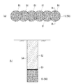
井戸2は、図1に示すように、井戸用ストレーナパイプ4と、該井戸用ストレーナパイプ4の外周全域に外方に向かって複数積層した所定幅の第1〜第3フィルタ外周層5a〜5cとから構成される。なお、井戸用ストレーナパイプ4の内部には、汲み上げ用の高揚程ポンプ(図示略)等が設置され、複数の集水孔10を介して井戸用ストレーナパイプ4内に流入する地層の地下水を汲み上げて外部に排水する。
Hereinafter, embodiments for carrying out the present invention will be described in detail with reference to FIGS.
The
A well 2 (see FIG. 1) and a plurality of water collecting members 3 (see FIGS. 4C and 4D) connected to the well 2 underground and capable of collecting water are provided.
As shown in FIG. 1, the
井戸用ストレーナパイプ4は、外周壁に集水孔10を複数穿設した鋼管等で構成される。
井戸用ストレーナパイプ4の外周全域には、最も外周から内方に向かって第1フィルタ外周層5a、第2フィルタ外周層5b、第3フィルタ外周層5cがこの順序で積層される。第1フィルタ外周層5aには第1フィルタ材7aが、また、第2フィルタ外周層5bには第2フィルタ材7bが、さらに、第3フィルタ外周層5cには第3フィルタ材7cがそれぞれ敷き詰められて構成される。各第1、第2及び第3フィルタ材7a、7b、7cの粒径の大小は、第1フィルタ材7a<第2フィルタ材7b<第3フィルタ材7cとなる。
The
The first filter outer
また、井戸用ストレーナパイプ4内の底部全域には、最も底部から上方に向かって第1フィルタ材7aよりなる第1フィルタ底部層6a、第2フィルタ材7b(>第1フィルタ部材7a)よりなる第2フィルタ底部層6b、第3フィルタ材7c(>第2フィルタ部材7b)よりなる第3フィルタ底部層6cがこの順序で積層される。第1〜第3フィルタ材7a、7b、7cは、砕石、砂利、砂や硬質のプラスチック材等が使用される。
なお、本実施の形態では、井戸用ストレーナパイプ4の外周全域及び底部全域に3層のフィルタ層を積層したが、それ以上積層してもよい。
Further, the entire bottom portion in the
In the present embodiment, three filter layers are stacked on the entire outer periphery and bottom of the
集水部材3は、図4に示すように、外周壁に集水孔11を複数穿設した所定長さの鋼管等で構成される有孔管12と、該有孔管12内に充填されるフィルタ材15とから構成される。本実施形態では、有孔管12内にフィルタ材15を透水性を有する透水袋16を介して充填している。なお、フィルタ材15は、砕石、砂利、砂や硬質のプラスチック材等が使用される。
As shown in FIG. 4, the
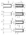
次に、本排水設備1の構築方法であって、特に、集水部材3を埋設する方法を図3及び図4に基づいて説明する。
まず、図3(a)に示すように、地下に第1ケーシングチューブ18a、18aを打ち込み、所定深さの縦長孔19a、19bを間隔を置いて複数構築する。
次に、図3(a)に示すように、隣接する縦長孔19a、19bのうち一方の縦長孔19aの内部から掘進機(図示略)を地中に略水平方向に押し出し、該掘進機の後に支持管であるヒューム管22を順次後続させて、複数のヒューム管22の管列を推進することで掘進機を他方の縦長孔19bまで到達させて、隣接する縦長孔19a、19b間を連結するように複数のヒューム管22を埋設する。
Next, a method for constructing the
First, as shown in FIG. 3A, the
Next, as shown in FIG. 3 (a), an excavator (not shown) is pushed out from the inside of one of the adjacent
次に、図4に示すように、有孔管12内にフィルタ材15入りの透水袋16を充填して構成した集水部材3を複数用意する。具体的には、図4(a)に示すように、有孔管12を立てた状態とする。続いて、図4(b)に示すように、立てた有孔管12内に透水袋16を入れて、該透水袋16の一端開口からフィルタ材15を該透水袋16内に隙間なく充填する。続いて、図4(c)に示すように、透水袋16の端部を結び、図4(d)に示すように、フィルタ材15入りの透水袋16を有孔管12に充填して構成した集水部材3を横向きに倒した状態とする。
次に、図3(b)及び(c)に示すように、一方の縦長孔19a内に集水部材3を横向きで順次挿入して、隣接する縦長孔19a、19b間に配置された各ヒューム管22を他方の縦長孔19b内へ順次押し出すように、各集水部材3の列を推進させて、隣接する縦長孔19a、19b間の各ヒューム管22を全て集水部材3に入れ替える。
Next, as shown in FIG. 4, a plurality of
Next, as shown in FIGS. 3 (b) and 3 (c), the
また、集水部材3を隣接する縦長孔19a、19b間に埋設する方法に係る他の実施形態を図5に基づいて説明する。
図5(a)に示すように、隣接する縦長孔19a、19b間に複数のヒューム管22(図3(a)参照)を埋設した後、一方の縦長孔19aの内部に有孔管12だけを順次挿入して、隣接する縦長孔19a、19b間に配置された各ヒューム管22を他方の縦長孔19b内へ順次押し出すようにして有孔管12の管列を推進させて、隣接する縦長孔19a、19b間の各ヒューム管22を全て有孔管12に入れ替える。
次に、図5(b)に示すように、フィルタ材15入りの透水袋16を一方の縦長孔19aの内部を経由して各有孔管12の内部に挿入した後、圧送装置23からフィルタ材15入りの透水袋16に砂や水等を噴射して所定位置まで圧送する。これを繰り返して、全有孔管12内に複数のフィルタ材15入りの透水袋16を隙間なく充填するようにする。
なお、隣接する縦長孔19a、19bを地下で連結した複数の有孔管12内にフィルタ材15入りの透水袋16を充填せずに、隣接する縦長孔19a、19b間を有孔管12だけで連結する場合もある。
Another embodiment relating to a method of embedding the
As shown in FIG. 5 (a), after embedding a plurality of fume tubes 22 (see FIG. 3 (a)) between adjacent vertically
Next, as shown in FIG.5 (b), after inserting the water-
In addition, without filling the water
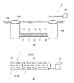
次に、本排水設備1の構築方法であって、特に、縦長孔19a、19bに図1に示す井戸2の構築する方法を図2に基づいて説明する。
まず、図2(a)及び(b)に示すように、縦長孔19a、19bを形成した第1ケーシングチューブ18a内の底部全域に最も小さい粒径の第1フィルタ材7aにより所定高さの第1フィルタ底部層6aを構築する。
Next, a method for constructing the
First, as shown in FIGS. 2 (a) and 2 (b), the
次に、図2(c)に示すように、第1ケーシングチューブ18aよりも若干小径の第2ケーシングチューブ18bを、第1ケーシングチューブ18aの内部に該第1ケーシングチューブ18aと同軸状に配置する。続いて、図2(d)に示すように、第1フィルタ材7aを、第1ケーシングチューブ18aと第2ケーシングチューブ18bとの間の隙間に第1フィルタ底部層6a上面から地表面に至る範囲で充填して第1フィルタ外周層5aを構築する。続いて、第1ケーシングチューブ18aを抜き取る。
Next, as shown in FIG. 2C, a
次に、図2(e)に示すように、第2ケーシングチューブ18b内の第1フィルタ底部層6a上全域に第2フィルタ材7b(>第1フィルタ部材7a)により所定高さの第2フィルタ底部層6bを構築する。
次に、第2ケーシングチューブ18bよりも若干小径の第3ケーシングチューブ18cを、第2ケーシングチューブ18bの内部に該第2ケーシングチューブ18bと同軸状に配置する。続いて、図2(f)に示すように、第2フィルタ材7bを、第2ケーシングチューブ18bと第3ケーシングチューブ18cとの間の隙間に第2フィルタ底部層6b上から地表面に至る範囲で充填して第2フィルタ外周層5bを構築する。続いて、第2ケーシングチューブ18bを抜き取る。
Next, as shown in FIG. 2 (e), the
Next, the
次に、図2(g)に示すように、第3ケーシングチューブ18c内の第2フィルタ底部層6b上全域に第3フィルタ材7c(>第2フィルタ部材7b)により所定高さの第3フィルタ底部層6cを構築する。
次に、第3ケーシングチューブ18cよりも若干小径の第4ケーシングチューブ18dを、第3ケーシングチューブ18cの内部に該第3ケーシングチューブ18cと同軸状に配置する。続いて、図2(h)に示すように、第3フィルタ材7cを、第3ケーシングチューブ18cと第4ケーシングチューブ18dとの間の隙間に第3フィルタ底部層6c上から地表面に至る範囲で充填して第3フィルタ外周層5cを構築する。続いて、第3ケーシングチューブ18cを抜き取る。
Next, as shown in FIG. 2G, a third filter having a predetermined height is formed on the entire area of the second filter
Next, a
最後に、第4ケーシングチューブ18dの内側に井戸用ストレーナパイプ4を配置した後、第4ケーシングチューブ18dを抜き取り、井戸2を完成させる。また、井戸用ストレーナパイプ4の内部には、汲み上げ用の高揚程ポンプ(図示略)等が設置される。
Finally, after the
なお、上述した第2〜第4ケーシングチューブ18b〜18dを、透水性を有するチューブで構成すれば、第2〜第4ケーシングチューブ18b〜18dを抜き取る工程を省略することができる。この形態の場合には、第3フィルタ外周層5cと井戸用ストレーナパイプ4との間に第4ケーシングチューブ18dが位置するようになる。この結果、第3フィルタ外周層5cからの第3フィルタ材7cが井戸用ストレーナパイプ4の集水孔10を介して井戸用ストレーナパイプ4の内部に侵入して堆積することを抑制することができる。
また、本実施の形態では、縦長孔19a、19bの両方に井戸2を構築したが、複数の縦長孔19a、19bのうち少なくとも1箇所に井戸2を構築してもよい。
In addition, if the 2nd-
Moreover, in this Embodiment, although the
以上説明したように、本発明の実施の形態に係る排水設備1では、特に井戸2については、井戸用ストレーナパイプ4の外周全域に、最も外周から内方に向かって第1フィルタ材7aよりなる第1フィルタ外周層5a、第2フィルタ材7bよりなる第2フィルタ外周層5b、第3フィルタ材7cよりなる第3フィルタ外周層5cをこの順序で積層して、第1、第2及び第3フィルタ材7a、7b、7cの粒径の大小を、第1フィルタ材7a<第2フィルタ材7b<第3フィルタ材7cとする。これによって、井戸用ストレーナパイプ4周辺の地層を安定させることできるので、各井戸2を長期間使用しても閉塞する可能性はほとんどない。また、大型の井戸用ストレーナパイプを採用することなく、井戸2の外周における地山からの地下水の集水性を向上させることもできる。また、集水部材3については、複数の集水孔11を有する有孔管12と、該有孔管12内に充填されるフィルタ材15とから構成されるので、長期間使用しても有孔管12が閉塞する可能性はほとんどないので、集水機能を失うことはない。
As described above, in the
本発明の実施の形態に係る排水設備1において、井戸2に複数の集水部材3を地下で連結するには、井戸2を構築するための隣接する縦長孔19a、19b間に、支持管としてのヒューム管22を一方の縦長孔19aを利用して複数埋設した後、一方の縦長孔19a内へ順次集水部材3を挿入すると共に各ヒューム管22を他方の縦長孔19b内へ順次押し出すようにして、各ヒューム管22を全て集水部材3に入れ替えるようする。その後、隣接する縦長孔19a、19bのうち少なくとも1箇所に図1に示す井戸2を構築する。これにより、従来のように、構造上不要な地面の開削施工等を無くすことができ、施工性を向上させることができる。
In the
1 排水設備,2 井戸,3 集水部材,4 井戸用ストレーナパイプ,5a〜5c 第1〜第3フィルタ外周層,6a〜6c 第1〜第3フィルタ底部層,7a〜7c 第1〜第3フィルタ部材,10 集水孔(井戸用ストレーナパイプ側),11 集水孔(有孔管側),12 有孔管,15 フィルタ部材,16 透水袋,19a、19b 縦長孔,22 ヒューム管(支持管)
DESCRIPTION OF
Claims (7)
前記井戸は、外周壁に複数の集水孔を有する井戸用ストレーナパイプの外周に、粒径の相違するフィルタ材の層を外方に向かって複数積層して構成され、これら各層のフィルタ材の粒径を最も外周から内方に向かって大きくすることを特徴とする排水設備。 A drainage facility with a well for collecting and draining groundwater,
The well is formed by laminating a plurality of layers of filter materials having different particle diameters outward on the outer periphery of a well strainer pipe having a plurality of water collecting holes on the outer peripheral wall. A drainage facility characterized by increasing the particle diameter from the outermost to the innermost.
前記集水部材は、複数の集水孔を有する有孔管と、該有孔管内に充填されるフィルタ材とからなることを特徴とする排水設備。 A drainage facility comprising a well and a water collecting member connected to the well underground and capable of collecting water, and collecting and draining groundwater;
The drainage facility, wherein the water collecting member includes a perforated pipe having a plurality of water collecting holes and a filter material filled in the perforated pipe.
地表面から地下に向かう縦長孔を間隔を置いて複数構築するステップと、
複数の支持管を順次前記縦長孔の内部から挿入して、各縦長孔間を地下で各支持管により連結するステップと、
複数の集水孔を有する有孔管内に、内部にフィルタ材を充填した透水袋を充填した前記集水部材を複数製造するステップと、
前記複数の集水部材を順次前記縦長孔の内部から挿入して、各縦長孔間の各支持管を押し出すようにして、各支持管を各集水部材に入れ替えるステップと、
前記複数の縦長孔に対して少なくとも1箇所に井戸を構築するステップと、
を備えたことを特徴とする排水設備の構築方法。 A method for constructing a drainage facility comprising a well and a water collecting member connected to the well underground and capable of collecting water,
A step of constructing a plurality of elongated holes at intervals from the ground surface to the basement,
Inserting a plurality of support tubes sequentially from the inside of the elongated holes, and connecting the elongated holes with the respective support tubes underground;
In the perforated pipe having a plurality of water collection holes, a step of producing a plurality of the water collection members filled with a water permeable bag filled with a filter material inside;
Inserting the plurality of water collecting members sequentially from the inside of the vertically long holes and pushing out the supporting tubes between the vertically long holes, and replacing each supporting tube with each water collecting member;
Building a well in at least one location for the plurality of elongated holes;
A method for constructing a drainage facility characterized by comprising:
地表面から地下に向かう縦長孔を間隔を置いて複数構築するステップと、
複数の支持管を順次前記縦長孔の内部から挿入して、各縦長孔間を地下で各支持管により連結するステップと、
複数の前記有孔管を順次前記縦長孔の内部から挿入して、各縦長孔間の各支持管を押し出すようにして、各支持管を各有孔管に入れ替えるステップと、
前記複数の縦長孔に対して少なくとも1箇所に井戸を構築するステップと、
を備えたことを特徴とする排水設備の構築方法。 A construction method of a drainage facility comprising a well and a perforated pipe connected to the well underground and having a water collecting hole,
A step of constructing a plurality of elongated holes at intervals from the ground surface to the basement,
Inserting a plurality of support tubes sequentially from the inside of the elongated holes, and connecting the elongated holes with the respective support tubes underground;
Inserting a plurality of the perforated pipes sequentially from the inside of the vertically long holes, and pushing out each supporting pipe between the vertically long holes, replacing each supporting pipe with each perforated pipe;
Building a well in at least one location for the plurality of elongated holes;
A method for constructing a drainage facility characterized by comprising:
Priority Applications (1)
| Application Number | Priority Date | Filing Date | Title |
|---|---|---|---|
| JP2011045021A JP2012180694A (en) | 2011-03-02 | 2011-03-02 | Drainage system and construction method thereof |
Applications Claiming Priority (1)
| Application Number | Priority Date | Filing Date | Title |
|---|---|---|---|
| JP2011045021A JP2012180694A (en) | 2011-03-02 | 2011-03-02 | Drainage system and construction method thereof |
Publications (1)
| Publication Number | Publication Date |
|---|---|
| JP2012180694A true JP2012180694A (en) | 2012-09-20 |
Family
ID=47012106
Family Applications (1)
| Application Number | Title | Priority Date | Filing Date |
|---|---|---|---|
| JP2011045021A Withdrawn JP2012180694A (en) | 2011-03-02 | 2011-03-02 | Drainage system and construction method thereof |
Country Status (1)
| Country | Link |
|---|---|
| JP (1) | JP2012180694A (en) |
Cited By (1)
| Publication number | Priority date | Publication date | Assignee | Title |
|---|---|---|---|---|
| CN114991254A (en) * | 2022-05-20 | 2022-09-02 | 中水北方勘测设计研究有限责任公司 | Treatment method for solving annual attenuation of water yield of radiation well |
-
2011
- 2011-03-02 JP JP2011045021A patent/JP2012180694A/en not_active Withdrawn
Cited By (1)
| Publication number | Priority date | Publication date | Assignee | Title |
|---|---|---|---|---|
| CN114991254A (en) * | 2022-05-20 | 2022-09-02 | 中水北方勘测设计研究有限责任公司 | Treatment method for solving annual attenuation of water yield of radiation well |
Similar Documents
| Publication | Publication Date | Title |
|---|---|---|
| US7909535B2 (en) | Soil drainage system | |
| CN203421330U (en) | Detachable-washing double-wall sand filtering drain pipe | |
| JP2010095977A (en) | Drainage structure for underground water, and construction method for tunnel having the same | |
| CN104499560B (en) | Combined rainwater seepage well and construction method | |
| US11987971B2 (en) | Systems and methods for underground storage of storm and other water sources | |
| CN110102565A (en) | The extraction well system with anti-blockage function applied to the extracting of soil multiphase | |
| JP2009197411A (en) | Construction method for lowering underground water level | |
| JP2022130793A (en) | Drain cartridge for underground drain channel in land developed by banking, and forming method of underground drain channel in land developed by banking using the drain cartridge | |
| JP5182903B2 (en) | Osmotic structure, water collecting facility with osmotic structure, and installation method of osmotic structure | |
| JP2008208521A (en) | Rainwater storage facility | |
| JP2012180694A (en) | Drainage system and construction method thereof | |
| JP6037770B2 (en) | Drainage system and drainage method | |
| JP2001173028A (en) | Manchurian well type water collecting method and it water buried collecting conduit device | |
| KR100641069B1 (en) | Apparatus for Channelling Groundwater and The Method Therefor | |
| JP2003328344A (en) | High lift wellpoint apparatus | |
| JP2005120738A (en) | Intake device | |
| KR101837033B1 (en) | Method for constructing collecting wells based on large-scale excavation and ground improvement and a collecting well constructed by the method | |
| CN208830283U (en) | A kind of nursery stock weeper drain | |
| JP5110730B1 (en) | Water intake or drainage method using liquefaction countermeasure drain | |
| JP2021534341A (en) | Rods for water collection and transportation and rod assembly parts | |
| JP7345165B2 (en) | Non-overflow type infiltration system and its construction method | |
| JP3821810B2 (en) | Water collecting apparatus and construction method of water collecting apparatus | |
| CN117468485A (en) | Drainage device, assembly and construction method for periphery of ground warehouse | |
| KR100641032B1 (en) | Method and structure for draining underground water of poor subsoil | |
| KR102084579B1 (en) | Pile type groundwater collector |
Legal Events
| Date | Code | Title | Description |
|---|---|---|---|
| A300 | Withdrawal of application because of no request for examination |
Free format text: JAPANESE INTERMEDIATE CODE: A300 Effective date: 20140513 |