JP2012178201A - Optical pickup device - Google Patents
Optical pickup device Download PDFInfo
- Publication number
- JP2012178201A JP2012178201A JP2011041045A JP2011041045A JP2012178201A JP 2012178201 A JP2012178201 A JP 2012178201A JP 2011041045 A JP2011041045 A JP 2011041045A JP 2011041045 A JP2011041045 A JP 2011041045A JP 2012178201 A JP2012178201 A JP 2012178201A
- Authority
- JP
- Japan
- Prior art keywords
- laser
- light
- light receiving
- receiving unit
- optical
- Prior art date
- Legal status (The legal status is an assumption and is not a legal conclusion. Google has not performed a legal analysis and makes no representation as to the accuracy of the status listed.)
- Withdrawn
Links
Images


Abstract
Description
本発明は、光ディスクに記録されている信号の読み出し動作や光ディスクに信号の記録動作をレーザー光によって行う光ピックアップ装置に関する。 The present invention relates to an optical pickup device that performs reading operation of a signal recorded on an optical disc and recording operation of a signal on an optical disc by laser light.
光ピックアップ装置から照射されるレーザー光を光ディスクの信号記録層に照射することによって信号の読み出し動作や信号の記録動作を行うことが出来る光ディスク装置が普及している。 2. Description of the Related Art Optical disk apparatuses that can perform signal reading operation and signal recording operation by irradiating a signal recording layer of an optical disk with laser light emitted from an optical pickup device have become widespread.
光ディスク装置としては、CDやDVDと呼ばれる光ディスクを使用するものが一般に普及しているが、最近では記録密度を向上させた光ディスク、即ちBlu−ray規格の光ディスクを使用するものが開発されている。 As an optical disk apparatus, an apparatus using an optical disk called a CD or a DVD is generally widespread. Recently, an optical disk with improved recording density, that is, an apparatus using a Blu-ray standard optical disk has been developed.
CD規格の光ディスクに記録されている信号の読み出し動作を行うレーザー光としては、波長が785nmである赤外光が使用され、DVD規格の光ディスクに記録されている信号の読み出し動作行うレーザー光としては、波長が655nmの赤色光が使用されている。 As a laser beam for performing a read operation of a signal recorded on a CD standard optical disc, an infrared light having a wavelength of 785 nm is used. As a laser beam for performing a read operation of a signal recorded on a DVD standard optical disc, , Red light having a wavelength of 655 nm is used.
また、CD規格の光ディスクにおける信号記録層と光ディスクの表面との間に設けられている透明な保護層の厚さは1.2mmであり、この信号記録層から信号の読み出し動作を行うために使用される対物レンズの開口数は、0.47と設定されている。そして、DVD規格の光ディスクにおける信号記録層と光ディスクの表面との間に設けられている透明な保護層の厚さは0.6mmであり、この信号記録層から信号の読み出し動作を行うために使用される対物レンズの開口数は、0.6と設定されている。 Further, the thickness of the transparent protective layer provided between the signal recording layer and the surface of the optical disc in the CD standard optical disc is 1.2 mm, and is used to read out signals from the signal recording layer. The numerical aperture of the objective lens to be set is set to 0.47. The thickness of the transparent protective layer provided between the signal recording layer in the DVD standard optical disc and the surface of the optical disc is 0.6 mm, and is used to read out signals from the signal recording layer. The numerical aperture of the objective lens to be set is set to 0.6.
斯かるCD規格及びDVD規格の光ディスクに対して、Blu−ray規格の光ディスクに記録されている信号の読み出し動作を行うレーザー光としては、波長が短いレーザー光、例えば波長が405nmの青紫色光が使用されている。 For such CD standard and DVD standard optical disks, the laser light for performing the read operation of the signals recorded on the Blu-ray standard optical disk is a laser light having a short wavelength, for example, a blue-violet light having a wavelength of 405 nm. It is used.
Blu−ray規格の光ディスクにおける信号記録層の上面に設けられている保護層の厚さは、0.1mmであり、この信号記録層から信号の読み出し動作を行うために使用される対物レンズの開口数は、0.85と設定されている。 The thickness of the protective layer provided on the upper surface of the signal recording layer in the Blu-ray standard optical disc is 0.1 mm, and the aperture of the objective lens used to read out signals from the signal recording layer The number is set to 0.85.
Blu−ray規格の光ディスクに設けられている信号記録層に記録されている信号の読み出し動作や該信号記録層に信号を記録するためには、レーザー光を集光させることによって生成されるレーザースポットの径を小さくする必要がある。所望のレーザースポット形状を得るために使用される対物レンズは、開口数が大きくなるだけでなく焦点距離が短くなるので、対物レンズの曲率半径が小さくなるという特徴がある。 In order to read signals recorded on a signal recording layer provided on a Blu-ray standard optical disc or to record signals on the signal recording layer, a laser spot generated by condensing laser light. It is necessary to reduce the diameter. The objective lens used to obtain a desired laser spot shape has a feature that not only the numerical aperture is increased but also the focal length is shortened, so that the radius of curvature of the objective lens is reduced.
前述したCD規格、DVD規格及びBlu−ray規格の全ての光ディスクに記録されている信号の読み出し動作や記録動作を行うことが出来る光ディスク装置が製品化されているが、斯かる光ディスク装置に組み込まれる光ピックアップ装置として、Blu−ray規格の光ディスクに記録されている信号の読み出し動作を行う第1レーザー光を放射するレーザーダイオード、該レーザーダイオードから放射される第1レーザー光を信号記録層に集光させる第1対物レンズ、DVD規格の光ディスクに記録されている信号の読み出し動作を行う第2レーザー光及びCD規格の光ディスクに記録されている信号の読み出し動作を行う第3レーザー光を放射する2波長レーザーダイオード、そして第2レーザー光及び第3レーザー光を各光ディスクの信号記録層に集光させる第2対物レンズが組み込まれた光ピックアップ装置が一般に採用されている(特許文献1参照。)。 An optical disc apparatus capable of reading and recording signals recorded on all the optical discs of the CD standard, the DVD standard, and the Blu-ray standard described above has been commercialized, and is incorporated into such an optical disc apparatus. As an optical pickup device, a laser diode that emits a first laser beam that performs an operation of reading a signal recorded on a Blu-ray standard optical disc, and the first laser beam emitted from the laser diode is condensed on a signal recording layer. Two wavelengths for emitting a first objective lens, a second laser beam for performing a read operation of a signal recorded on a DVD standard optical disc, and a third laser beam for performing a read operation of a signal recorded on a CD standard optical disc Laser diode, and second and third laser beams Optical pickup device in which the second objective lens is incorporated for converging the signal recording layer of the click is generally employed (see Patent Document 1.).
規格の異なる3つの光ディスクに記録されている信号の読み出し動作を行うことが出来るように構成された光ピックアップ装置には、特許文献1に記載されているように第1レーザー光を放射するレーザーダイオードと第2レーザー光及び第3レーザー光の2つのレーザー光を放射する2波長レーザーダイオードの2つのレーザーダイオードが一般に使用されているが、最近では、第1レーザー光、第2レーザー光及び第3レーザー光の異なる波長の3つのレーザー光を放射させるように構成された3波長レーザーダイオードを使用する光ピックアップ装置が提案されている(特許文献2参照。)。 An optical pickup device configured to be able to read out signals recorded on three optical discs having different standards includes a laser diode that emits a first laser beam as described in Patent Document 1. In general, two laser diodes of two-wavelength laser diodes that emit two laser beams, ie, a second laser beam and a third laser beam, are used. Recently, a first laser beam, a second laser beam, and a third laser beam are used. There has been proposed an optical pickup device using a three-wavelength laser diode configured to emit three laser beams having different wavelengths of laser beams (see Patent Document 2).
また、光ピックアップ装置は、信号記録層から反射される戻り光を光検出器に照射させ、該光検出器から得られる信号を利用してフォーカス制御動作、トラッキング制御動作及び信号の復調動作を行うための信号を得るように構成されている。 Further, the optical pickup device irradiates the photodetector with return light reflected from the signal recording layer, and performs a focus control operation, a tracking control operation, and a signal demodulation operation using a signal obtained from the photodetector. Is configured to obtain a signal for.
斯かる光ピックアップ装置では、戻り光を光検出器を構成するセンサーに照射させるように構成されているが、センサーに対する戻り光の照射位置を正確に行う必要がある。しかしながら、光学系を構成する各光学部品の取付位置のずれ等によってセンサーに対する戻り光の照射位置がずれることがあり、光検出器の位置を調整する動作、所謂XYポジション調整と呼ばれる動作が行われる。 Such an optical pickup device is configured to irradiate return light to a sensor constituting the photodetector, but it is necessary to accurately perform the irradiation position of the return light on the sensor. However, the irradiation position of the return light with respect to the sensor may be shifted due to a displacement of the mounting position of each optical component constituting the optical system, and an operation called a so-called XY position adjustment is performed. .
斯かるXYポジション調整を行っても戻り光の照射位置を最適な位置に調整することが出来ない場合や光検出器の位置を変位調整することが出来ない場合があり、斯かる問題を解決する方法として光検出器を構成するセンサーから得られる信号のレベルを調整する技術が提案されている(特許文献3参照。)。 Even if such XY position adjustment is performed, the irradiation position of the return light cannot be adjusted to the optimum position, or the position of the photodetector cannot be adjusted in some cases, and the problem is solved. As a method, a technique for adjusting the level of a signal obtained from a sensor constituting a photodetector has been proposed (see Patent Document 3).
特許文献2に記載されているような3波長レーザーダイオードを使用する光ピックアップ装置について、図1及び図2を参照して説明する。
An optical pickup device using a three-wavelength laser diode as described in
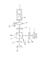
図1において、1は例えば波長が405nmの青紫色光である第1レーザー光を生成放射する第1レーザーチップ、例えば波長が655nmの赤色光である第2レーザー光を生成放射する第2レーザーチップ及び例えば波長が785nmの赤外色光である第3レーザー光を生成放射する第3レーザーチップが同一のケース内に収納されている3波長レーザーダイオードである。 In FIG. 1, reference numeral 1 denotes a first laser chip that generates and emits first laser light that is blue-violet light having a wavelength of 405 nm, for example, a second laser chip that generates and emits second laser light that is red light having a wavelength of 655 nm. And, for example, a three-wavelength laser diode in which a third laser chip that generates and emits third laser light that is infrared color light having a wavelength of 785 nm is housed in the same case.
2は前記3波長レーザーダイオード1から放射される第1レーザー光、第2レーザー光及び第3レーザー光が入射される回折格子であり、波長が異なる各レーザー光を0次光であるメインビーム、+1次光及び−1次光である2つのサブビームに分離する回折格子部2aと入射されるレーザー光をS方向の直線偏光光に変換する1/2波長板2bとより構成されている。
3は前記回折格子2を透過して入射される第1レーザー光、第2レーザー光及び第3レーザー光のS偏光光を反射させるとともに後述する光路を通して光ディスクから反射されてくる第1レーザー光、第2レーザー光及び第3レーザー光の戻り光であるP偏光光を透過させる制御膜3aが形成されている偏光ビームスプリッタである。
4は前記偏光ビームスプリッタ3にて反射された第1レーザー光、第2レーザー光及び第3レーザー光が入射される位置に設けられているとともに3つの異なる波長のレーザー光に対応して入射されるレーザー光を直線偏光光から円偏光光に、また反対に円偏光光から直線偏光光に変換する作用を成す3波長対応型の1/4波長板である。
4 is provided at a position where the first laser beam, the second laser beam, and the third laser beam reflected by the polarizing
5は前記1/4波長板4を透過した第1レーザー光、第2レーザー光及び第3レーザー光が入射されるとともに入射されるレーザー光を平行光に変換するコリメートレンズであり、該コリメートレンズ5の光軸方向への変位動作によって光ディスクの保護層の厚さに起因して生じる球面収差を補正するように構成されている。6は前記コリメートレンズ5を光軸方向へ変位させる収差補正用モーターである。
7は第1レーザー光を第1光ディスクD1(図2参照)に設けられている信号記録層L1に集光させる第1対物レンズ、8は第2レーザー光を第2光ディスクD2に設けられている信号記録層L2に集光させるとともに第3レーザー光を第3光ディスクD3に設けられている信号記録層L3に集光させる2波長対応の第2対物レンズである。斯かる構成において、第1対物レンズ7と第2対物レンズ8とは、例えば4本の支持ワイヤーによって光ディスクの面に対して直角方向であるフォーカシング方向への変位動作及び光ディスクの径方向であるトラッキング方向への変位動作を行うことが出来るように支持されているレンズホルダーと呼ばれる部材に搭載されている。
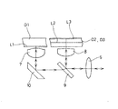
前記コリメートレンズ5を透過した第1レーザー光、第2レーザー光及び第3レーザー光は、図2に示す光学系によって第1対物レンズ7及び第2対物レンズ8に導かれるように構成されている。図2において、9は波長選択性素子であり、第1レーザー光を透過させるとともに第2レーザー光及び第3レーザー光を第2対物レンズ8方向へ反射させるように構成されている。10は前記波長選択性素子9を透過した第1レーザー光を第1対物レンズ7方向へ反射させる立ち上げミラーである。斯かる構成は特許文献1に記載されている技術と同一であるので、その説明は省略する。
The first laser light, the second laser light, and the third laser light transmitted through the
斯かる構成において、コリメートレンズ5を透過した第1レーザー光は、前記波長選択性素子9を透過するとともに立ち上げミラー10にて反射されて第1対物レンズ7に入射されることになる。このようにして第1対物レンズ7に入射された第1レーザー光は、該第1対物レンズ7の集光動作によって第1光ディスクD1に設けられている信号記録層L1に集光されることになる。
In such a configuration, the first laser light transmitted through the
また、前記コリメートレンズ5を透過した第2レーザー光は、前記波長選択性素子9にて反射されて第2対物レンズ8に入射されることになる。このようにして第2対物レンズ8に入射された第2レーザー光は、該第2対物レンズ8の集光動作によって第2光ディスクD2に設けられている信号記録層L2に集光されることになる。そして、コリメートレンズ5を透過した第3レーザー光は、前記波長選択性素子9にて反射されて第2対物レンズ8に入射されることになる。このようにして第2対物レンズ8に入射された第3レーザー光は、該第2対物レンズ8の集光動作によって第3光ディスクD3に設けられている信号記録層L3に集光されることになる。
The second laser light transmitted through the
斯かる構成において、3波長レーザーダイオード1に組み込まれている第1レーザーチップから放射された第1レーザー光は、回折格子2、偏光ビームスプリッタ3、1/4波長板4、コリメートレンズ5、波長選択性素子9及び立ち上げミラー10を介して第1対物レンズ7に入射された後、該第1対物レンズ7の集光動作によって第1光ディスクD1に設けられている信号記録層L1に集光スポットとして照射されるが、前記信号記録層L1に照射された第1レーザー光は該信号記録層L1にて戻り光として反射されることになる。
In such a configuration, the first laser light emitted from the first laser chip incorporated in the three-wavelength laser diode 1 is the
また、3波長レーザーダイオード1に組み込まれている第2レーザーチップから放射された第2レーザー光は、回折格子2、偏光ビームスプリッタ3、1/4波長板4、コリメートレンズ5及び波長選択性素子9を介して第2対物レンズ8に入射された後、該第2対物レンズ8の集光動作によって第2光ディスクD2に設けられている信号記録層L2に集光スポットとして照射されるが、前記信号記録層L2に照射された第2レーザー光は該信号記録層L2にて戻り光として反射されることになる。
The second laser light emitted from the second laser chip incorporated in the three-wavelength laser diode 1 is a
そして、3波長レーザーダイオード3に組み込まれている第3レーザーチップから放射された第3レーザー光は、回折格子2、偏光ビームスプリッタ3、1/4波長板4、コリメートレンズ5及び波長選択性素子9を介して第2対物レンズ8に入射された後、該第2対物レンズ8の集光動作によって第3光ディスクD3に設けられている信号記録層L3に集光スポットとして照射されるが、前記信号記録層L3に照射された第3レーザー光は該信号記録層L3にて戻り光として反射されることになる。
The third laser light emitted from the third laser chip incorporated in the three-
第1光ディスクD1の信号記録層L1から反射された第1レーザー光の戻り光は、第1対物レンズ7、立ち上げミラー10、波長選択性素子9、コリメートレンズ5及び1/4波長板4を通して偏光ビームスプリッタ3に入射される。このようにして偏光ビームスプリッタ3に入射される戻り光は、前記1/4波長板4による位相変更動作によってP方向の直線偏光光に変更されている。従って、斯かる第1レーザー光の戻り光は前記偏光ビームスプリッタ3の制御膜3aにて反射されることはなく、制御用レーザー光として該偏光ビームスプリッタ3を透過することになる。
The return light of the first laser beam reflected from the signal recording layer L1 of the first optical disc D1 passes through the first
また、第2光ディスクD2の信号記録層L2から反射された第2レーザー光の戻り光は、第2対物レンズ8、波長選択性素子9、コリメートレンズ5及び1/4波長板4を通して偏光ビームスプリッタ3に入射される。このようにして偏光ビームスプリッタ3に入射される戻り光は、前記1/4波長板4による位相変更動作によってP方向の直線偏光光に変更されている。従って、斯かる第2レーザー光の戻り光は前記偏光ビームスプリッタ3の制御膜3aにて反射されることはなく、制御用レーザー光として該偏光ビームスプリッタ3を透過することになる。
The return light of the second laser light reflected from the signal recording layer L2 of the second optical disc D2 passes through the second
そして、第3光ディスクD3の信号記録層L3から反射された第3レーザー光の戻り光は、第2対物レンズ8、波長選択性素子9、コリメートレンズ5及び1/4波長板4を通して偏光ビームスプリッタ3に入射される。このようにして偏光ビームスプリッタ3に入射される戻り光は、前記1/4波長板4による位相変更動作によってP方向の直線偏光光に変更されている。従って、斯かる第3レーザー光の戻り光は前記偏光ビームスプリッタ3の制御膜3aにて反射されることはなく、制御用レーザー光として該偏光ビームスプリッタ3を透過することになる。
Then, the return light of the third laser light reflected from the signal recording layer L3 of the third optical disc D3 passes through the second
11は前記偏光ビームスプリッタ3の制御膜3aを透過した戻り光である制御用レーザー光が入射されるアナモフィックレンズであり、フォーカス制御動作やトラッキング制御動作を行う信号を生成するために該制御用レーザー光に対して作用するものである。斯かるアナモフィックレンズ11は、シリンドリカルレンズと呼ばれるレンズであり、凹レンズにて構成されている。
12は前記アナモフィックレンズ11を通して制御用レーザー光が照射される光検出器であり、周知の4分割センサー等が第1レーザー光、第2レーザー光及び第3レーザー光に対応して設けられており、メインビームの照射動作によって光ディスクの信号記録層に記録されている信号の読み出し動作に伴う信号生成動作及び非点収差法によるフォーカシング制御動作を行うためのフォーカスエラー信号生成動作、そして2つのサブビームの照射動作によってトラッキング制御動作を行うためのトラッキングエラー信号生成動作を行うように構成されている。斯かる各種の信号生成のための制御動作は、周知であるので、その説明は省略する。
異なる波長の第1レーザー光、第2レーザー光及び第3レーザー光を放射する3つのレーザーチップが同一の筐体内に設けられている3波長レーザーダイオード1及び第1レーザー光、第2レーザー光及び第3レーザー光の戻り光に対応したセンサーが同一の筐体内に設けられている光検出器12を使用する光ピックアップ装置は、前述したように構成されているが、次に3波長レーザーダイオード1及び光検出器12について図3及び図4を参照にして説明する。
A three-wavelength laser diode 1, a first laser beam, a second laser beam, and three laser chips that emit a first laser beam, a second laser beam, and a third laser beam having different wavelengths are provided in the same housing. The optical pickup device using the
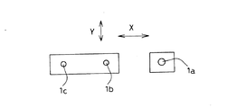
図3は3波長レーザーダイオード1に組み込まれているレーザーチップの配置を示すものであり、1aは波長が短い第1レーザー光を放射する第1レーザーチップ、1bは前記第1レーザー光より波長が長い第2レーザー光を放射する第2レーザーチップ、1cは前記第2レーザー光より波長が長い第3レーザー光を放射する第3レーザーチップである。
FIG. 3 shows the arrangement of the laser chips incorporated in the three-wavelength laser diode 1, wherein 1a is a first laser chip that emits a first laser beam having a short wavelength, and 1b has a wavelength that is shorter than that of the first laser beam. A
斯かる構成において、第2レーザーチップ1bと第3レーザーチップ1cとは、単一の基板上に半導体技術であるモノリシック技術にて製造され、第1レーザーチップ1aは、前記第2レーザーチップ1b及び第3レーザーチップ1cが形成されている基板とは異なる基板上に形成されており、両者はハイブリッド技術によって1つの筐体内に設けられている。また、前記第1レーザーチップ1a、第2レーザーチップ1b及び第3レーザーチップ1cは、図示したように矢印X方向に直線状に配置されている。
In such a configuration, the
3波長レーザーダイオード1に組み込まれる第2レーザーチップ1bと第3レーザーチップ1cとは、前述したようにモノリシック技術にて製造されているので、両者の位置関係は誤差が少なく正確な位置に配置されるが、第1レーザーチップ1aはハイブリッド技術によって3波長レーザーダイオード1の筐体内に組み込まれるので、その配置には誤差が生じることになる。即ち、3波長レーザーダイオードでは、矢印X方向に対する各レーザーチップ間の間隔、即ちピッチに誤差が生じるが、矢印Y方向の位置には大きな誤差が発生することはない。
Since the
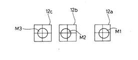
図4は光検出器12に組み込まれている受光素子の配置を示すものであり、12aは第1レーザー光の戻り光が照射される位置に設けられている第1受光部、12bは第2レーザー光の戻り光が照射される位置に設けられている第2受光部、12cは前記第3レーザー光の戻り光が照射される位置に設けられている第3受光部である。また、斯かる第1受光部12a、第2受光部12b及び第3受光部12cは、図示したように矢印X方向に直線状に配置されている。
FIG. 4 shows the arrangement of the light receiving elements incorporated in the
図4は第1レーザー光、第2レーザー光及び第3レーザー光を構成するメインビームが照射されるメインビーム用の受光部を示すものであり、サブビーム用の受光部は、メインビーム用の受光部に対して最適な位置に配置されている。即ち、メインビームが照射されるメインビーム用の受光部に対してレーザー光のメインビームが最適な位置にて照射されている場合には、サブビーム用の受光部に対してサブビームが最適な位置にて照射されるようにされている。 FIG. 4 shows a light receiving portion for a main beam irradiated with a main beam constituting the first laser light, the second laser light, and the third laser light. The light receiving portion for the sub beam is a light receiving portion for the main beam. It is arranged at an optimal position with respect to the part. That is, when the main beam of the laser beam is irradiated at the optimum position with respect to the light receiving portion for the main beam irradiated with the main beam, the sub beam is placed at the optimum position with respect to the light receiving portion for the sub beam. It is supposed to be irradiated.
また、第1レーザー光の戻り光が照射される第1受光部12a、第2レーザー光の戻り光が照射される第2受光部12b及び第3レーザー光の戻り光が照射される第3受光部12cは、図示したように4つに分割されたセンサーにて構成されている。斯かる4つに分割されたセンサーから得られる信号を利用してフォーカスエラー信号等を周知のように生成するように構成されている。
The first
図4において、M1は第1レーザー光の戻り光が照射されて第1受光部12a上に生成される第1レーザースポット、M2は第2レーザー光の戻り光が照射されて第2受光部12b上に生成される第2レーザースポット、M3は第3レーザー光の戻り光が照射されて第3受光部12c上に生成される第3レーザースポットである。
In FIG. 4, M1 is a first laser spot generated on the first
図4は第1レーザースポットM1、第2レーザースポットM2及び第3レーザースポットM3が、夫々第1受光部12a、第2受光部12b及び第3受光部12cに設けられている4分割センサーを構成する4つのセンサーの中心部、即ち最適な位置に照射された状態を示すものである。
FIG. 4 shows a quadrant sensor in which the first laser spot M1, the second laser spot M2, and the third laser spot M3 are provided in the first
光ピックアップ装置の組み立て作業によって光検出器12の位置を調整するXYポジション調整が行われるが、斯かる調整動作は、例えば第2レーザー光の戻り光が照射される第2受光部12bの最適な位置に第2レーザースポットM2が位置するように行われる。即ち、第2レーザー光を生成放射する第2レーザーチップ1bと第3レーザー光を生成放射する第3レーザーチップ1cは、前述したようにモノリシック技術にて製造されているので、両者の位置関係は正確に設定することが出来る。従って、例えば第2レーザー光の戻り光にて生成される第2レーザースポットM2の位置を第2受光部12bの中央部、即ち最適な位置になるようにXYポジション調整を行えば第3レーザー光の戻り光にて生成される第3レーザースポットM3の位置を第3受光部12cの中央部、即ち最適な位置に配置させることが出来る。
The XY position adjustment for adjusting the position of the
図4は前述した調整動作を行った状態を示すものであり、第2レーザースポットM2及び第3レーザースポットM3は、第2受光部12b及び第3受光部12cの最適な位置に照射生成される。そして、3波長レーザーダイオード1内に設けられている第1レーザーチップ1a、第2レーザーチップ1b及び第3レーザーチップ1cの配置、即ちピッチが正確であるとともに光ピックアップ装置を構成する各光学部品の配置が正確であれば、前述した第2レーザースポットM2のXYポジション調整が行われると、第1レーザー光の戻り光が照射されて生成される第1レーザースポットM1は図示したように第1受光部12aの最適な位置に位置することになる。
FIG. 4 shows a state in which the above-described adjustment operation has been performed. The second laser spot M2 and the third laser spot M3 are irradiated and generated at optimal positions of the second
しかしながら、実際には、3波長レーザーダイオード1内に設けられている第1レーザーチップ1a、第2レーザーチップ1b及び第3レーザーチップ1cの配置、即ちピッチは正確ではなく、各レーザーチップ間のピッチが相違することがある。各レーザーチップ間の配置ピッチが正確でない3波長レーザーダイオード1を使用した場合には、第2レーザースポットM2を第2受光部12bの最適な位置になるようにXY調整を行っても第1レーザースポットM1及び第3レーザースポットM3が第1受光部12a及び第3受光部12cの最適な位置からずれることになる。
However, in actuality, the arrangement, that is, the pitch of the
第1レーザースポットM1及び第3レーザースポットM3の位置が最適な位置からずれている場合には、第1受光部12a及び第3受光部12cを構成するセンサーから得られる信号のレベルを調整することによって対応しているが、調整することが出来ない程スポットの位置がずれる場合があり、不良品として処分されるという問題がある。
When the positions of the first laser spot M1 and the third laser spot M3 are deviated from the optimum positions, the level of the signal obtained from the sensor constituting the first
本発明は、斯かる問題を解決することが出来る光ピックアップ装置を提供しようとするものである。 The present invention is intended to provide an optical pickup device that can solve such a problem.
本発明は、波長が短い第1レーザー光を放射する第1レーザーチップ、第1レーザー光より波長が長い第2レーザー光を放射する第2レーザーチップ及び第2レーザー光より波長が長い第3レーザー光を放射する第3レーザーチップが同一の筐体内に直線状に配置されている3波長レーザーダイオードから放射される各レーザー光を光ディスクの表面から信号記録層までの距離が異なる第1光ディスク、第2光ディスク及び第3光ディスクに設けられている信号記録層に集光させるとともに各信号記録層から反射される第1レーザー光の戻り光を受光する第1受光部、第2レーザー光の戻り光を受光する第2受光部及び第3レーザー光の戻り光を受光する第3受光部が同一の筐体内に直線状に配置されている光検出器を備え、前記光検出器に戻り光を導くアナモフィックレンズを光軸方向への変位を可能に設け、該アナモフィックレンズを光軸方向へ変位させることによって第1受光部、第2受光部及び第3受光部へ照射される戻り光にて生成されるレーザースポットのピッチを調整するようにしたことを特徴とするものである。 The present invention includes a first laser chip that emits a first laser light having a short wavelength, a second laser chip that emits a second laser light having a longer wavelength than the first laser light, and a third laser having a longer wavelength than the second laser light. A first optical disc having a different distance from the surface of the optical disc to the signal recording layer for each laser beam emitted from a three-wavelength laser diode in which a third laser chip for emitting light is linearly arranged in the same housing; A first light receiving portion for collecting the return light of the first laser light reflected from each signal recording layer and condensing the signal recording layers provided on the second optical disc and the third optical disc; and the return light of the second laser light. The second light-receiving unit that receives light and the third light-receiving unit that receives the return light of the third laser light include a photodetector arranged in a straight line in the same housing, and the photodetector An anamorphic lens that guides the reflected light is provided so as to be displaceable in the optical axis direction, and the return light irradiated to the first light receiving unit, the second light receiving unit, and the third light receiving unit by displacing the anamorphic lens in the optical axis direction. The pitch of the laser spot generated by the method is adjusted.
また、本発明は、アナモフィックレンズの光軸方向への変位によるレーザースポットの変位方向を第1受光部、第2受光部及び第3受光部の配置方向と一致させたことを特徴とするものである。 Further, the present invention is characterized in that the displacement direction of the laser spot due to the displacement of the anamorphic lens in the optical axis direction coincides with the arrangement direction of the first light receiving unit, the second light receiving unit, and the third light receiving unit. is there.
そして、本発明は、第1受光部、第2受光部及び第3受光部の各受光部を4つに分割された4分割センサーにて構成したことを特徴とするものである。 The present invention is characterized in that each light receiving portion of the first light receiving portion, the second light receiving portion, and the third light receiving portion is constituted by a four-divided sensor divided into four.
また、本発明は、第2レーザー光の戻り光にて生成されるレーザースポットの位置を第2受光部の中央部に一致させた状態にてアナモフィックレンズの変位調整を行うようにしたことを特徴とするものである。 Further, the present invention is characterized in that the displacement adjustment of the anamorphic lens is performed in a state where the position of the laser spot generated by the return light of the second laser beam is made coincident with the central portion of the second light receiving unit. It is what.
更に、本発明は、第1受光部及び第3受光部を構成するより各センサーより得られる信号のレベルを電気的に調整する利得調整回路を設け、該利得調整回路によって第1受光部及び第3受光部に対するレーザースポットの位置ずれを補正するようにしたことを特徴とするものである。 Furthermore, the present invention provides a gain adjustment circuit that electrically adjusts the level of a signal obtained from each sensor by configuring the first light receiving unit and the third light receiving unit, and the first light receiving unit and the first light receiving unit are provided by the gain adjustment circuit. The laser spot position shift with respect to the three light receiving parts is corrected.
また、本発明は、第1レーザー光の戻り光にて生成されるレーザースポットの位置を第1受光部の中央部に一致させた状態にてアナモフィックレンズの変位調整を行うようにしたことを特徴とするものである。 Further, the present invention is characterized in that the displacement adjustment of the anamorphic lens is performed in a state where the position of the laser spot generated by the return light of the first laser beam is coincident with the central portion of the first light receiving unit. It is what.
そして、本発明は、第2受光部及び第3受光部を構成するより各センサーより得られる信号のレベルを電気的に調整する利得調整回路を設け、該利得調整回路によって第2受光部及び第3受光部に対するレーザースポットの位置ずれを補正するようにしたことを特徴とするものである。 In the present invention, a gain adjustment circuit that electrically adjusts the level of a signal obtained from each sensor is provided by configuring the second light receiving unit and the third light receiving unit, and the second light receiving unit and the second light receiving unit are provided by the gain adjustment circuit. The laser spot position shift with respect to the three light receiving parts is corrected.
本発明は、波長が短い第1レーザー光を放射する第1レーザーチップ、第1レーザー光より波長が長い第2レーザー光を放射する第2レーザーチップ及び第2レーザー光より波長が長い第3レーザー光を放射する第3レーザーチップが同一の筐体内に直線状に配置されている3波長レーザーダイオードから放射される各レーザー光を光ディスクの表面から信号記録層までの距離が異なる第1光ディスク、第2光ディスク及び第3光ディスクに設けられている信号記録層に集光させるとともに各信号記録層から反射される第1レーザー光の戻り光を受光する第1受光部、第2レーザー光の戻り光を受光する第2受光部及び第3レーザー光の戻り光を受光する第3受光部が同一の筐体内に直線状に配置されている光検出器を備えた光ピックアップ装置において、前記光検出器に戻り光を導くアナモフィックレンズを光軸方向への変位を可能に設け、該アナモフィックレンズを光軸方向へ変位させることによって第1受光部、第2受光部及び第3受光部へ照射される戻り光にて生成されるレーザースポットのピッチを調整するようにしたので、レーザーチップの配置がずれた3波長レーザーダイオードを使用しても不良品の数を大幅に減らすことが出来る。 The present invention includes a first laser chip that emits a first laser light having a short wavelength, a second laser chip that emits a second laser light having a longer wavelength than the first laser light, and a third laser having a longer wavelength than the second laser light. A first optical disc having a different distance from the surface of the optical disc to the signal recording layer for each laser beam emitted from a three-wavelength laser diode in which a third laser chip for emitting light is linearly arranged in the same housing; A first light receiving portion for collecting the return light of the first laser light reflected from each signal recording layer and condensing the signal recording layers provided on the second optical disc and the third optical disc; and the return light of the second laser light. An optical pickup provided with a photodetector in which a second light receiving portion for receiving light and a third light receiving portion for receiving return light of the third laser light are linearly arranged in the same housing. The anamorphic lens that guides the return light to the photodetector is provided so as to be capable of displacement in the optical axis direction, and the anamorphic lens is displaced in the optical axis direction to displace the first light receiving portion, the second light receiving portion, and the third light receiving portion. Since the pitch of the laser spot generated by the return light irradiated to the light receiving unit is adjusted, the number of defective products can be greatly reduced even if a three-wavelength laser diode with a misaligned laser chip is used. I can do it.
異なる3つの波長のレーザー光を放射する3波長レーザーダイオードと各波長の戻り光が照射される3つの受光部を備えた光検出器が組み込まれた光ピックアップ装置に関するものである。 The present invention relates to an optical pickup device in which a three-wavelength laser diode that emits laser beams of three different wavelengths and a photodetector including three light-receiving units that are irradiated with return light of each wavelength are incorporated.
本発明の光ピックアップ装置は、図1に示した光学系の概略図において、偏光ビームスプリッタ3を透過した戻り光である制御用レーザー光を光検出器12に導くべく設けられているアナモフィックレンズ11を光軸方向、即ち矢印A方向及びB方向へ変位可能にしたことを特徴とするものである。
The optical pickup device of the present invention is an
図5は第2レーザー光の戻り光にて生成される第2レーザースポットM2をXY調整作業によって第2受光部12bの中心部、即ち最適な位置に調整した状態を示すものである。同図より明らかなように第1受光部12aに対する第1レーザースポットM1の位置が最適な位置より第2受光部12bの方向、即ち内側へずれているとともに第3受光部12cに対する第3レーザースポットM3の位置が最適な位置より第2受光部12bの方向、即ち内側へずれている。
FIG. 5 shows a state in which the second laser spot M2 generated by the return light of the second laser light is adjusted to the center of the second
斯かる状態は、3波長レーザーダイオード1に組み込まれている第1レーザーチップ1aと第2レーザーチップ1bとの間隔、即ちピッチが規格より短く、また第3レーザーチップ1cと第2レーザーチップ1bとのピッチが規格より短いことや光学系の部品の位置ずれに起因して発生したものである。
In such a state, the distance between the
本発明は、図5に示すように第1レーザースポットM1及び第3レーザースポットM3が共に第2レーザースポットM2側にずれている場合、即ちピッチが小さい場合には、アナモフィックレンズ11をレーザー光の入射側、即ち矢印A方向へ変位させることによってずれを補正するようにしたものである。
In the present invention, as shown in FIG. 5, when both the first laser spot M1 and the third laser spot M3 are shifted to the second laser spot M2 side, that is, when the pitch is small, the
即ち、凹レンズであるアナモフィックレンズ11を矢印A方向へ変位させると、光学系の倍率が下がるので、第1レーザースポットM1が第2レーザースポットM2から離れる方向、即ち外側へ移動するとともに第3レーザースポットM3が第2レーザースポットM2から離れる方向、即ち外側へ移動する。斯かる調整動作を行うことによって図4に示す位置、即ち第1レーザースポットM1、第2レーザースポットM2及び第3レーザースポットM3を各々第1受光部12a、第2受光部12b及び第3受光部12cの最適な位置に移動させることが出来る。
That is, if the
図5に示すように第1レーザースポットM1及び第3レーザースポットM3が共に第2レーザースポットM2側にずれている場合、前述した調整動作が行われるので、各受光部から各レーザー光に対するフォーカス制御動作及びトラッキング制御動作を行うために適した制御信号を得ることが出来る。 As shown in FIG. 5, when both the first laser spot M1 and the third laser spot M3 are shifted to the second laser spot M2 side, the adjustment operation described above is performed, so that focus control for each laser beam from each light receiving unit is performed. A control signal suitable for performing the operation and the tracking control operation can be obtained.
図5に示した状態は、3波長レーザーダイオード1に組み込まれている第1レーザーチップ1aと第2レーザーチップ1bとの間隔、即ちピッチが規格より短く、また第3レーザーチップ1cと第2レーザーチップ1bとのピッチが規格より短いことや光学系の位置ずれに起因して発生したものであるが、次に反対に第1レーザーチップ1aと第2レーザーチップ1bとの間隔、即ちピッチが規格より長く、また第3レーザーチップ1cと第2レーザーチップ1bとのピッチが規格より長い場合について説明する。
The state shown in FIG. 5 is that the distance between the
図6はレーザーチップ間のピッチが規格より長い場合の各受光部と各レーザースポットとの位置関係を示すものである。同図より明らかなように第1受光部12aに対する第1レーザースポットM1の位置が最適な位置より第2受光部12bの反対方向、即ち外側へずれているとともに第3受光部12cに対する第3レーザースポットM3の位置が最適な位置より第2受光部12bの反対方向、即ち外側へずれている。
FIG. 6 shows the positional relationship between each light receiving portion and each laser spot when the pitch between laser chips is longer than the standard. As is apparent from the figure, the position of the first laser spot M1 with respect to the first
本発明は、図6に示すように第1レーザースポットM1及び第3レーザースポットM3が共に第2レーザースポットM2の反対側にずれている場合、即ちピッチが大きい場合には、アナモフィックレンズ11をレーザー光の出射側、即ち矢印B方向へ変位させることによってずれを補正するようにしたものである。
In the present invention, as shown in FIG. 6, when both the first laser spot M1 and the third laser spot M3 are shifted to the opposite side of the second laser spot M2, that is, when the pitch is large, the
即ち、凹レンズであるアナモフィックレンズ11を矢印B方向へ変位させると、光学系の倍率が上がるので、第1レーザースポットM1が第2レーザースポットM2方向、即ち内側へ移動するとともに第3レーザースポットM3が第2レーザースポットM2方向、即ち内側へ移動する。斯かる調整動作を行うことによって図4に示す位置、即ち第1レーザースポットM1、第2レーザースポットM2及び第3レーザースポットM3を各々第1受光部12a、第2受光部12b及び第3受光部12cの最適な位置に移動させることが出来る。
That is, if the
図6に示すように第1レーザースポットM1及び第3レーザースポットM3が共に第2レーザースポットM2の反対側にずれている場合、前述した調整動作が行われるので、各受光部から各レーザー光に対するフォーカス制御動作及びトラッキング制御動作を行うために適した制御信号を得ることが出来る。 As shown in FIG. 6, when both the first laser spot M1 and the third laser spot M3 are shifted to the opposite side of the second laser spot M2, the adjustment operation described above is performed. A control signal suitable for performing the focus control operation and the tracking control operation can be obtained.
前述した図5及び図6は第1レーザーチップ1aと第2レーザーチップ1bとのピッチ及び第2レーザーチップ1bと第3レーザーチップ1cとのピッチが共に規格に対して同一方向、即ち規格に対して同一方向に短い場合及び同一方向に長い場合であるが、次にピッチの規格に対するずれの方向が異なる場合について説明する。
5 and 6 described above, the pitch between the
図7は第1レーザーチップ1aと第2レーザーチップ1bとのピッチが規格より長く、第2レーザーチップ1bと第3レーザーチップ1cとのピッチが規格より短い場合のXY調整前の各受光部と各レーザースポットとの位置関係を示すものである。
FIG. 7 shows each light receiving unit before XY adjustment when the pitch between the
斯かる場合、本発明では、例えば第2レーザー光の戻り光にて生成される第2レーザースポットM2を第2受光部12bの中心部、即ち最適な位置に調整する作業、即ちXY調整動作を行う。図8は斯かるXY調整を行った状態を示すものである。
In such a case, in the present invention, for example, the operation of adjusting the second laser spot M2 generated by the return light of the second laser beam to the center of the second
斯かるXY調整が行われると、図8に示すように第2レーザースポットM2は第2受光部12bの中心部、即ち最適な位置に調整されることになる。斯かる状態にあるとき、第1レーザースポットM1及び第3レーザースポットM3は、各々第1受光部12a及び第3受光部12cに対して外側及び内側にずれた状態になる。
When such XY adjustment is performed, as shown in FIG. 8, the second laser spot M2 is adjusted to the center of the second
斯かる状態において、本発明では、アナモフィックレンズ11を矢印B方向へ移動させることによって第1レーザースポットM1を内側へ移動させる動作、即ち第1受光部12aの最適な位置に移動させる調整動作を行う。斯かる調整動作を行った場合に第3レーザースポットM3も内側へ移動することになるが、その移動調整動作は、第3受光部12cを構成する各センサーから得られる信号をセンサー毎に設けられている利得調整回路によって調整可能な範囲にて行われることになる。勿論、第1レーザースポットM1を第1受光部12aの中心部、即ち最適な位置まで移動させることが不可能な場合には、第1受光部12aを構成する各センサーから得られる信号をセンサー毎に設けられている利得調整回路にて調整を行うことになる。
In such a state, in the present invention, an operation of moving the first laser spot M1 inward by moving the
図7に示すように第1レーザースポットM1、第2レーザースポットM2及び第3レーザースポットM3が異なる方向にずれている場合、前述した調整動作が行われるので、各受光部から各レーザー光に対するフォーカス制御動作及びトラッキング制御動作を行うために適した制御信号を得ることが出来る。 As shown in FIG. 7, when the first laser spot M1, the second laser spot M2, and the third laser spot M3 are shifted in different directions, the adjustment operation described above is performed, so that the focus on each laser beam from each light receiving unit. A control signal suitable for performing the control operation and the tracking control operation can be obtained.
前述したように各レーザースポットと各受光部との関係が図7に示す状態にあるとき、第2レーザースポットM2を第2受光部12bの最適な位置に調整するXY調整作業を行う場合の動作は行われるが、次に第1レーザースポットM1をXY調整作業によって第1受光部12aの最適な位置に調整する場合について説明する。図9は斯かるXY調整を行った状態を示すものである。
As described above, when the relationship between each laser spot and each light receiving unit is in the state shown in FIG. 7, the operation when the XY adjustment operation for adjusting the second laser spot M2 to the optimum position of the second
斯かるXY調整が行われると、図9に示すように第1レーザースポットM1は第1受光部12aの中心部、即ち最適な位置に調整されることになる。斯かる状態にあるとき、第2レーザースポットM2及び第3レーザースポットM3は、各々第1受光部12a及び第3受光部12cに対して外側にずれた状態になる。
When such XY adjustment is performed, as shown in FIG. 9, the first laser spot M1 is adjusted to the center of the first
斯かる状態において、アナモフィックレンズ11を移動させる調整動作を行うことは出来ないので、本発明では電気的に調整動作を行うことになる。即ち、第2受光部12bを構成する各センサーから得られる信号をセンサー毎に設けられている利得調整回路にて調整するとともに第3受光部12cを構成する各センサーから得られる信号をセンサー毎に設けられている利得調整回路によって調整する動作が行われる。
In such a state, the adjustment operation for moving the
図7に示すように第1レーザースポットM1、第2レーザースポットM2及び第3レーザースポットM3が異なる方向にずれている場合、前述した調整動作が行われるので、各受光部から各レーザー光に対するフォーカス制御動作及びトラッキング制御動作を行うために適した制御信号を得ることが出来る。 As shown in FIG. 7, when the first laser spot M1, the second laser spot M2, and the third laser spot M3 are shifted in different directions, the adjustment operation described above is performed, so that the focus on each laser beam from each light receiving unit. A control signal suitable for performing the control operation and the tracking control operation can be obtained.
以上に説明したように第1レーザーチップ1a、第2レーザーチップ1b及び第3レーザーチップ1c間のピッチのずれや光学系のずれに伴って第1レーザースポットM1、第2レーザースポットM2及び第3レーザースポットM3の第1受光部12a、第2受光部12b及び第3受光部12cに対する照射位置がずれていた場合の調整動作は行われるが、アナモフィックレンズ11の変位動作及びセンサーから得られる信号の利得調整動作によって補正できない場合には不良として処理されることになる。しかしながら、本発明によれば前述したような調整動作を行うことが出来るので、従来に比較して不良品になる率を大幅に下げることが出来る。
As described above, the first laser spot M1, the second laser spot M2, and the
CD規格、DVD規格及びBlu−ray規格の光ディスク記録されている信号の読み出し動作を行う光ピックアップ装置に実施した場合について説明したが、その他の異なる規格の光ディスクに記録されている信号の読み出し動作を行うことが出来る光ピックアップ装置に実施することも出来る。 Although the description has been given of the case where the optical pickup apparatus that performs the reading operation of the signal recorded on the optical disc of the CD standard, the DVD standard, and the Blu-ray standard has been described, the reading operation of the signal recorded on the optical disc of another different standard has been described. It can also be implemented in an optical pickup device that can be used.
また、規格の異なる3種の光ディスクに設けられている信号記録層に3つのレーザー光を集光させるために2つの対物レンズを設けたが、1つの対物レンズによって3種の光ディスクに設けられている信号記録層に3つのレーザー光を集光させるように構成された光ピックアップ装置に実施することも出来る。 In addition, two objective lenses are provided for condensing three laser beams on the signal recording layers provided on three types of optical discs with different standards. However, one objective lens is provided on three types of optical discs. The present invention can also be implemented in an optical pickup device configured to focus three laser beams on a signal recording layer.
1 3波長レーザーダイオード
3 偏光ビームスプリッタ
4 1/4波長板
5 コリメートレンズ
7 第1対物レンズ
8 第2対物レンズ
12 光検出器
DESCRIPTION OF SYMBOLS 1 3
Claims (7)
Priority Applications (1)
| Application Number | Priority Date | Filing Date | Title |
|---|---|---|---|
| JP2011041045A JP2012178201A (en) | 2011-02-28 | 2011-02-28 | Optical pickup device |
Applications Claiming Priority (1)
| Application Number | Priority Date | Filing Date | Title |
|---|---|---|---|
| JP2011041045A JP2012178201A (en) | 2011-02-28 | 2011-02-28 | Optical pickup device |
Publications (1)
| Publication Number | Publication Date |
|---|---|
| JP2012178201A true JP2012178201A (en) | 2012-09-13 |
Family
ID=46979946
Family Applications (1)
| Application Number | Title | Priority Date | Filing Date |
|---|---|---|---|
| JP2011041045A Withdrawn JP2012178201A (en) | 2011-02-28 | 2011-02-28 | Optical pickup device |
Country Status (1)
| Country | Link |
|---|---|
| JP (1) | JP2012178201A (en) |
Cited By (1)
| Publication number | Priority date | Publication date | Assignee | Title |
|---|---|---|---|---|
| CN103528799A (en) * | 2013-10-24 | 2014-01-22 | 西安炬光科技有限公司 | Space polarization testing method and device for semiconductor laser device provided with multiple light emitting units |
-
2011
- 2011-02-28 JP JP2011041045A patent/JP2012178201A/en not_active Withdrawn
Cited By (1)
| Publication number | Priority date | Publication date | Assignee | Title |
|---|---|---|---|---|
| CN103528799A (en) * | 2013-10-24 | 2014-01-22 | 西安炬光科技有限公司 | Space polarization testing method and device for semiconductor laser device provided with multiple light emitting units |
Similar Documents
| Publication | Publication Date | Title |
|---|---|---|
| JP2011096329A (en) | Optical pickup device | |
| JP2011204336A (en) | Laser device, optical pickup device and method for manufacturing the same | |
| US7898910B2 (en) | Optical pickup apparatus | |
| US8427921B2 (en) | Light emitting device, optical pickup apparatus and method for manufacturing the same | |
| JP2012178201A (en) | Optical pickup device | |
| JP2012089185A (en) | Optical pickup device | |
| JP2013093083A (en) | Optical pickup device | |
| JP2008123605A (en) | Optical pickup device | |
| JP2004039109A (en) | Optical element, adjusting method therefor, optical pickup device using the same and optical reproducing device | |
| JP2012150852A (en) | Optical pickup device | |
| JP2011150775A (en) | Optical pickup apparatus | |
| JP2012150853A (en) | Optical pickup device | |
| US20080159113A1 (en) | Optical Pickup Apparatus | |
| JP2012155799A (en) | Optical pickup device | |
| JP2011129226A (en) | Optical pickup device | |
| JP2013143158A (en) | Optical pickup device | |
| JP2011154741A (en) | Optical pickup device | |
| JP2011070739A (en) | Optical pickup device | |
| JP2011070738A (en) | Optical pickup device | |
| JP2012169001A (en) | Optical pickup device | |
| JP2012009116A (en) | Optical pickup device | |
| JP2012099166A (en) | Photo-detector | |
| JP2012018724A (en) | Optical pickup device | |
| JP2012048786A (en) | Optical pickup device | |
| JP2009093726A (en) | Optical pickup device |
Legal Events
| Date | Code | Title | Description |
|---|---|---|---|
| A521 | Written amendment |
Free format text: JAPANESE INTERMEDIATE CODE: A821 Effective date: 20130708 |
|
| RD02 | Notification of acceptance of power of attorney |
Free format text: JAPANESE INTERMEDIATE CODE: A7422 Effective date: 20130708 |
|
| A300 | Withdrawal of application because of no request for examination |
Free format text: JAPANESE INTERMEDIATE CODE: A300 Effective date: 20140513 |