JP2012177671A - Fine aperiodic pattern projection device and method and three-dimensional measuring device using the same - Google Patents
Fine aperiodic pattern projection device and method and three-dimensional measuring device using the same Download PDFInfo
- Publication number
- JP2012177671A JP2012177671A JP2011058512A JP2011058512A JP2012177671A JP 2012177671 A JP2012177671 A JP 2012177671A JP 2011058512 A JP2011058512 A JP 2011058512A JP 2011058512 A JP2011058512 A JP 2011058512A JP 2012177671 A JP2012177671 A JP 2012177671A
- Authority
- JP
- Japan
- Prior art keywords
- pattern
- image
- measurement
- camera
- aperiodic
- Prior art date
- Legal status (The legal status is an assumption and is not a legal conclusion. Google has not performed a legal analysis and makes no representation as to the accuracy of the status listed.)
- Withdrawn
Links
Images


Abstract
Description
本発明は三次元形状識別技術に関する。とくにカメラで変形可能な物体の三次元形状計測において、同一点の識別プロセスを高速化、高精度にするためのパターン投影・計測技術に関する。 The present invention relates to a three-dimensional shape identification technique. In particular, the present invention relates to a pattern projection / measurement technique for increasing the speed and accuracy of the identification process of the same point in the three-dimensional shape measurement of an object that can be deformed by a camera.
リネンサプライ業では洗濯工場で大量のシーツやタオルを洗濯し、顧客にレンタルし使用後回収するサイクルでビジネスを行っている。現在、洗濯工程や仕上げ工程など多くの工程が大規模な洗濯機や展開仕上機、ロールアイロナー、折りたたみ仕上機などで行われている。
しかし洗濯ライン、仕上げラインの工程で最初に洗濯物を機械に投入する工程は布物をハンドリングする技術が確立されておらず人手で行われている。そのため洗濯工場での作業環境は感染の危険や高温等で過酷なため作業の自動化が望まれていた。
過去において,変形がない工業製品のハンドリングにおいては、ビジョンセンサーによる画像認識によりハンドリングするワークの姿勢を計測しワークの姿勢にあわせてロボットハンドがワークを把持して所望の場所に移動するようなハンドリングシステムがある。
しかしハンドリングするワークが可変シート状であるタオルやシーツのような布物のような柔軟物を展開したり分類するために形状計測をする用途の場合は、変形する布に対して、基準になる形状データがないため自動ハンドリングができなかった。In the linen supply industry, a large number of sheets and towels are washed in a laundry factory, and are rented to customers and collected after use. Currently, many processes such as washing and finishing processes are performed in large-scale washing machines, unfolding finishing machines, roll ironers, folding finishing machines, and the like.
However, the process of first putting the laundry into the machine in the washing line and finishing line processes is performed manually because the technology for handling the cloth has not been established. Therefore, since the work environment in the laundry factory is harsh due to the danger of infection and high temperatures, it is desired to automate the work.
In the past, handling of industrial products without deformation measures the posture of the workpiece to be handled by image recognition using a vision sensor, and the robot hand grips the workpiece and moves it to the desired location according to the posture of the workpiece. There is a system.
However, in the case of measuring the shape in order to develop or classify flexible objects such as towels or sheets such as towels and sheets that have a variable sheet shape to handle, it becomes a standard for deforming cloth. Automatic handling was not possible due to lack of shape data.
そこでこの部分を自動化するため、洗濯ラインに投入する洗濯物を種別に分類したり、投入コンベア上で計量する投入する試みや、仕上げラインにタオルやシーツを自動投入する取り組みがなされたが、実用化された例は少ない。その原因は布の変形パターンが無限にあり、設定した処理方法だけで対応できないことにある。
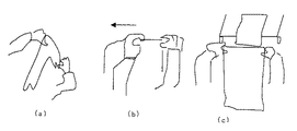
たとえば定型タオルを山積みの状態から拡げようとする場合、図2のように人は一つの布の端部を識別してそこから一辺をたぐり出す操作をして短辺の両端を持って全体を広げ、折りたたみをする仕上げ機に投入している。略端の識別には、一枚を取り出してその裾の部分を取り出す操作を行い、そこからの展開には端部周辺の辺を保持してその辺を展開する操作を行い一辺を拡げて吊り下げることで全面を拡げられる。Therefore, in order to automate this part, attempts were made to classify the laundry to be put into the laundry line, classify it on the loading conveyor, and automatically put towels and sheets into the finishing line. There are few examples. The cause is that the deformation pattern of the cloth is infinite and cannot be handled only by the set processing method.
For example, when trying to expand a regular towel from a piled-up state, as shown in Fig. 2, a person identifies the end of one cloth, and then pulls out one side from there to hold the entire end with the short ends. It is put into a finishing machine that spreads and folds. To identify the near end, take out one piece and take out the hem part. To expand from there, hold the side around the end and unfold the side. The whole surface can be expanded by lowering.
これらの操作をおこなうために特許文献1では、発明者が属する出願人により布ワークをハンドリングするための移動可能な保持ハンドやコンベアなどと光電センサのような通過確認センサとの組み合わせ、端部らしいところを出現させてタオルなどの布地を拡げる操作手段が開示されている。
他の手法として、過去に発明者らは、特許文献2または特許文献3に記載した手段により、空間領域にある布ワークの特徴部を視覚認識を用いてハンドリングする部位を識別しその部位の形状に対応してタオルを保持、展開操作している。
具体的には、山積みのタオルを一枚ずつ引き上げ、端部を出現させ、出現した端部をステレオカメラで形状計測し、端部周辺の辺の一部を把持し、そこからタオル全体を広げ出している。
とくに出現させた端部形状を認識し、ハンドが把持をして引き出し、なおかつ長辺の相手方端部周辺を別途保持してて吊り下げたときに、ある程度拡がって出現する短辺の相手方端部を計測して、その端部周辺の辺の形状を計測してロボットハンドの把持ポーズを決定している。そしてロボットハンドが一片を展開し吊り下げることで全面を展開している。In order to perform these operations, in
As another method, in the past, the inventors identified a part for handling a feature part of a cloth work in a spatial region using visual recognition by means described in
Specifically, pull up a pile of towels one by one, make the end appear, measure the shape of the appearing end with a stereo camera, grasp a part of the side around the end, and spread the entire towel from there I'm out.
In particular, it recognizes the end shape that has appeared, and when the hand grips and pulls it out, and also holds the periphery of the other side of the long side separately and hangs it, the short side of the other side appears. And the shape of the side around the end is measured to determine the grip pose of the robot hand. The robot hand unfolds and hangs a piece to expand the entire surface.
これらの手段は布の形状を計測し形状認識し、形状に合わせたハンドリング操作を行い展開し、仕上機に投入することで、仕上げライン全体を自動化するものである。
このような視覚認識結果をベースに対応動作を行うシステムに搭載する視覚認識部の視覚センサにはロボット動作に必要な動作を生成するための3次元空間内のワークの把持位置座標情報が必要になる。
具体的には、動作のために認識の正確性、ロバスト性、生産性のために計測の高速性、あるいはコスト面から構成をコンパクトにすること、さらには柔軟変形物の特徴部を的確かつ精度よく計測することが求められる。
発明者は記載した用途やその他の用途で、視覚による形状認識をベースにしたロボットハンドリングシステムを製作し実験検討を行った。これらのシステムでは把持位置情報を取得するため3次元計測手段を用いた。These means measure the shape of the cloth, recognize the shape, perform the handling operation according to the shape, develop it, and put it into the finishing machine to automate the entire finishing line.
The visual sensor of the visual recognition unit mounted on the system that performs the corresponding operation based on the visual recognition result as described above needs the grip position coordinate information of the workpiece in the three-dimensional space for generating the motion necessary for the robot motion. Become.
Specifically, the accuracy of recognition for operation, robustness, high speed of measurement for productivity, or compact configuration from the cost aspect, and accurate and accurate features of flexible deformations It is required to measure well.
The inventor made and experimented with a robot handling system based on visual shape recognition for the described and other uses. In these systems, a three-dimensional measuring means is used to acquire gripping position information.
前記の目的のため利用可能な先行技術として、発明者による特許文献4にはあおり光学系のステレオカメラとスリット光を走査して特許文献2記載の方法で連続的にステレオ撮影しながらスリット光を走査することで計測する手法が開示されている。
また発明者らによる特許文献5に記載した粗いドット配置と細かい格子配置をもつパターン光をワークに投影し、ステレオカメラで計測する手段が開示されている。図3(aおよびb)参照。
ここでは
(1)ステレオカメラ左右いずれかの基準画像と参照画像上のドット位置を識別し、対応 点づけしてその視差から高さを計算する。
(2)ドット位置を基準位置としてそのドットと周辺の格子線の位置間隔を基準画像と参 照画像にて、それぞれの画像で計測して相対的な視差を計算する。
(3)基準ドットの高さと視差による基準ドットからの相対高さ(奥行き)を計算するこ とで高速に高さを計算する手法である。
これにより計測したい端部周辺のタオルの三次元形状を計測し、端辺の把持に必要な3点の3次元情報を出力する視覚認識センサを展開装置に搭載することで、展開装置が展開処理を行い、自動で折りたたみ仕上げする仕上げ機へ投入できた。すなわち布の特徴識別技術と特許文献2、3によるハンドリング技術によりタオルの展開システムが可能になった。As a prior art that can be used for the above-mentioned purpose,
Also disclosed is a means for projecting pattern light having a rough dot arrangement and a fine lattice arrangement described in
Here, (1) the position of the dot on the reference image and the reference image on either the left or right side of the stereo camera is identified, the corresponding points are assigned, and the height is calculated from the parallax.
(2) Using the dot position as a reference position, the position interval between the dot and the surrounding grid line is measured in the reference image and the reference image for each image, and the relative parallax is calculated.
(3) A method for calculating the height at high speed by calculating the height of the reference dot and the relative height (depth) from the reference dot due to parallax.
With this, the deployment device measures the 3D shape of the towel around the edge you want to measure and installs a visual recognition sensor in the deployment device that outputs the 3D information required for gripping the edges. We were able to put it into a finishing machine that automatically folded and finished. In other words, the towel development system has become possible by the feature identification technology of the cloth and the handling technology according to
また、滑らかな表面をもつ計測対象物を三次元計測するための投影技術の先行出願として特許文献6がある。ここでは布を対象に限定していないが、なめらかな表面の計測対象物をステレオカメラで三次元計測するためにランダムパターンを生成し投影している。 Patent Document 6 is a prior application of a projection technique for three-dimensionally measuring a measurement object having a smooth surface. Although the cloth is not limited to the object here, a random pattern is generated and projected in order to measure a smooth surface measurement object three-dimensionally with a stereo camera.
特許文献1による布の展開方法は、布の変形が不規則であり、所望の展開に至る変形をしないとき展開が成功しないときがあり、作業者による効率を上回ることが困難だった。特許文献2、および特許文献3による布の展開手段では、前述同様に、画像認識するワーク特徴部の出現位置が想定外の位置で出現したり、想定以上の不規則な形状変化していると成功しないため、画像認識の対応可能な形状変化対応範囲の拡大が望まれていた。
特許文献4では、多数のステレオ組合せ画像から計測するため比較的安定的に三次元形状が計測可能であるが一回の認識に必要な撮像時間が長く、高速に判定結果を返すための認識センサとしては計測時間の増加から時間当たりの処理数が上がらない。
特許文献5では、布の形状が(小さな範囲の中で)大きく変化しているようなとき、たとえば格子間隔以内での変化について計測できなかった
またドットが左右のカメラ画像のどちらにも写っていないとその近傍の範囲の形状計測ができなかった。図4参照。
また計測密度を上げようとしてドット間隔、格子間隔を小さくしていくと探索視差線上で周期的に他の格子が存在するためミスマッチングの原因になった。In the cloth unfolding method according to
In
In
In addition, when the dot spacing and the lattice spacing were reduced to increase the measurement density, other lattices periodically existed on the search parallax line, which caused mismatching.
そこで布の変形パターンの多さに対応するため計測点の密度を最大化しようとしたときドットや格子はそれ自体が領域を持っている。ドットはテンプレートとして登録しておき、左右それぞれのカメラ画像上でパターンマッチングを行う方法を検討し以下にまとめた。画像を構成するM×Nのピクセルなかでドットや格子などのサイズm×nをもつ標識を配置するときには計測できる点数の限界がある。すなわち図5のようにM/mあるいはN/nが配置できる最大数である。
このことは、予め設定したテンプレートに合わせた投光パターンを設計する際に最大数以上の配置ができない。すなわち計測点の密度をそれ以上ふやせられない問題がある
このような問題に対する解決法として画像に存在するエッジが有効に存在するケースでは、左右いずれかの画像から切り出した部分画像をテンプレートとして、その部位に対応する相手方画像の視差線上で相間値計算して視差を計測する手法が公知であるが本発明の課題である滑らかな表面形状の部分を計測するのはそのままではできない。これに対応するため特許文献6では、乱数生成により発生したコードを二次元パターンにして非周期性パターンを生成するが乱数生成の段階で偶然発生する繰り返しパターンを除去するような(検定対応等の統計的対応)アルゴリズムが必要である。またランダムパターン投光装置が複雑でありコンパクト化が困難であったTherefore, when trying to maximize the density of measurement points in order to cope with the large number of deformation patterns of the cloth, dots and grids themselves have areas. Dots were registered as templates, and a method of pattern matching on the left and right camera images was studied and summarized below. There is a limit to the number of points that can be measured when a marker having a size m × n, such as a dot or a grid, is arranged among M × N pixels constituting an image. That is, as shown in FIG. 5, M / m or N / n is the maximum number that can be arranged.
This means that a maximum number of arrangements cannot be made when designing a light projection pattern that matches a preset template. That is, there is a problem that the density of the measurement points cannot be further increased. In the case where the edge that exists in the image exists effectively as a solution to such a problem, a partial image cut out from either the left or right image is used as a template. A technique for measuring a parallax by calculating an interphase value on a parallax line of a counterpart image corresponding to a part is known, but it is not possible to measure a smooth surface shape portion as a problem of the present invention as it is. In order to cope with this, in Patent Document 6, a non-periodic pattern is generated by converting a code generated by random number generation into a two-dimensional pattern, but a repetitive pattern that occurs by chance at the stage of random number generation is removed (such as test correspondence). Statistical correspondence) algorithm is required. Also, the random pattern projector is complicated and difficult to make compact.
そこで本発明は以下の課題を解決するものである。
柔軟に変形するもの、例えば布のような、滑らかなシート状の対象物であっても、カメラにより高速・高密度に計測物表面の3次元形状を識別するため、表面の計測点を含む微細領域に、計測領域内のなかにおいてユニークなパターンを投影する。
ステレオカメラで同一点を左右画像上の位置を同定可能にするため、計測箇所毎にユニークさをもつパターン光をワークに投影すること。
前記カメラによる画像を布の把持ハンドリングすべき特徴部の形状を識別すること、その把持位置をロボットハンドが把持し布地を整形することを解決すべき課題とするTherefore, the present invention solves the following problems.
Even a softly deformed object, for example, a smooth sheet-like object such as a cloth, can be used to identify the three-dimensional shape of the surface of the object at high speed and high density with a camera. A unique pattern is projected onto the area within the measurement area.
To make it possible to identify the position of the same point on the left and right images with a stereo camera, project pattern light with uniqueness for each measurement location.
Identifying the shape of a characteristic part to be gripped and handled from the image by the camera, and solving the problem that the robot hand grasps the gripped position and shapes the cloth.
本発明の技術思想は、三次元形状計測をおこなう場合において
なめらかな表面を含む計測物を計測するためにパターンを投影することと、
そのパターンは計測空間範囲のサイズにかかわらずどの計測点に対しても計測点周辺の微少表面にユニークとなるパターン投影をおこなうことである。
平面空間において無限にひろがる空間であっても敷き詰めることを平面充填という。敷き詰める基本図形をタイルあるいはセルという。1種類で平面充填できるタイルの図形は正方形や平行四辺形など公知のものがあるがこれらは周期性を有し、それぞれの一部領域のパターン形状は限定された一部平面のなかでもユニークでない。
そこで複数のタイルを用いた非周期パターンの平面充填が公知である。タイルの方向が非周期であるから、適度なサイズをもてば、限定された一部平面のなかではユニークさがある。投影装置で非周期パターンをワーク表面に投影することでユニークなマークをつければ滑らかなワーク表面もそれぞれの計測位置がユニークな標識がつけられる。The technical idea of the present invention is to project a pattern to measure a measurement object including a smooth surface when performing three-dimensional shape measurement,
The pattern is to perform a unique pattern projection on the minute surface around the measurement point for any measurement point regardless of the size of the measurement space range.
Filling even a space that extends infinitely in a planar space is called planar filling. The basic figure to be spread is called a tile or cell. There are known types of tiles that can be filled in a single plane, such as squares and parallelograms, but these have periodicity, and the pattern shape of each partial area is not unique among limited partial planes. .
Thus, planar filling of non-periodic patterns using a plurality of tiles is known. Since the direction of the tile is non-periodic, it has uniqueness in a limited partial plane if it has an appropriate size. If a unique mark is created by projecting an aperiodic pattern onto the workpiece surface with a projection device, a smooth workpiece surface can be labeled with a unique measurement position.
非周期パターンは公知でありいくつかの種類があるが、以下に記載したSir.Roger Penroseが発表したペンローズ・タイリングと呼ばれるパターンは以下の設定のもとに生成されるものであり非周期パターンの特徴を持つ。
[ペンローズ・タイリングの基本性質]
(1)図6(a)に記載のように内角が(1/5)π[rad]および(4/5)π[rad]の菱形(シンと呼ぶ)と(2/5)π[rad]および(3/5)π[rad]の菱形(ファットと呼ぶ)の2種類のみで平面上の空間充填が可能である。
(2)接続方法は図6(a)のように決まっている。菱形は他の菱形と結合するとき実線どうし、または破線どうしを方向を揃えて結合する。
(3)[分割][統合][段階的な微細化]図6(b、c)のように一つの菱形セルは数個のさらに小さな菱形セルに分割ができる。そのため分割を繰り返すことで無限に微細なパターンにすることができる。
(4)反対に結合を繰り返せば平面において無限の空間を充填できる。
(5)無限平面でのファット:シンの二つの菱形の個数割合が、無理数である黄金比φ=(1+√5)/2であることから非周期性をもつということが数学的に公知である。図6(d)ではシンの半分を分割したファットとシンのそれぞれ半分にしたときの面積比が黄金比になることを示すものである。 シンはファット1個とシン1個を生みファットはファット2個とシン1個を生成する。これを無限に繰り返したときの個数比はフィボナッチ数列の隣り合う二項の比が黄金比に収束することと同じである。一個のファット:シンの面積比はφ:1であるから無限空間での面積比は、φ2:1に収束する。
(6)並進対称性がない(並進移動しても完全に一致することがない。例えば、三角形や四角形、六角形を接続して平面充填した場合は、並進移動すると完全にかさなる部分がある)
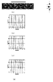
(7)平面を充填するペンローズ・タイリングと同一平面上にある直線の交点の間隔距離は非周期的であること図7(a)は109×52ピクセルのペンローズ・タイリングパターンの一部であり、中心部に水平に35ピクセルの直線の線分を設定し、その線分上の画像の輝度値をプロットしたものであり、図7(b)は中心から2ピクセル上に線分をずらしたとき、図3のcは線分が中心において、図7(c)は中心から2ピクセル下に線分をずらしたときのグラフである。小さい移動量でも異なるパターンを見せるため、計測点を含む微少領域が直線状の形状であってもマッチングができることを示した
(8)ペンローズ・タイリングはセルの内部と境界の辺部の2色で構成できることは当然だが、図8に示すように4色あるいは3色で境界線に色がなくても、3色で全てのセルを塗り分けられる。図8(a)はそれぞれの菱形を二色に分割し、計4色て配置した例、図8(b)は3色で配置した例である。
(9)[線][交点]セルを構成する線の方向は本発明で使用する菱形の内角のが(1/5)π、(2/5)π、(3/5)π、(4/5)πの4種類であるからこれから発生する境界線の角度は最大で2π/((1/5)π)であるから10種類である。
(10)交点は3個から10個のセルの角の先端点が重なる。Non-periodic patterns are known and there are several types, but Sir. A pattern called Penrose tiling announced by Roger Penrose is generated under the following settings and has a characteristic of an aperiodic pattern.
[Basic properties of Penrose tiling]
(1) As shown in FIG. 6 (a), rhombuses (referred to as thin) and (2/5) π [rad] whose inner angles are (1/5) π [rad] and (4/5) π [rad]. ] And (3/5) π [rad] rhombus (referred to as fat), the space filling on the plane is possible.
(2) The connection method is determined as shown in FIG. When diamonds are combined with other diamonds, solid lines or broken lines are connected with their directions aligned.
(3) [Division] [Integration] [Stepwise refinement] As shown in FIGS. 6B and 6C, one diamond cell can be divided into several smaller diamond cells. Therefore, an infinitely fine pattern can be obtained by repeating the division.
(4) On the contrary, if the coupling is repeated, an infinite space can be filled in the plane.
(5) Fat on an infinite plane: Mathematically known to have non-periodicity because the ratio of the number of two rhombuses of thin is an irrational golden ratio φ = (1 + √5) / 2 It is. FIG. 6D shows that the area ratio when the half of thin is divided into half of fat and thin is the golden ratio. A thin produces one fat and one thin, and a fat generates two fats and one thin. When this is repeated indefinitely, the number ratio is the same as the ratio of two adjacent terms in the Fibonacci sequence converges to the golden ratio. Since the area ratio of one fat: sin is φ: 1, the area ratio in the infinite space converges to φ 2 : 1.
(6) There is no translational symmetry (they do not completely match even if they are translated. For example, when a plane is filled by connecting triangles, quadrangles, and hexagons, there is a part that is completely bulky when translated)
(7) The distance between the intersections of the straight lines on the same plane as the Penrose tiling that fills the plane is aperiodic. FIG. 7A is a part of the Penrose tiling pattern of 109 × 52 pixels. Yes, a straight line segment of 35 pixels is set horizontally in the center, and the luminance value of the image on the line segment is plotted. FIG. 7B shows the line segment shifted 2 pixels above the center. FIG. 3c is a graph when the line segment is centered, and FIG. 7C is a graph when the line segment is shifted 2 pixels below the center. (8) Penrose tiling has two colors, the inside of the cell and the edge of the boundary, because it shows a different pattern even with a small amount of movement, so the matching can be done even if the minute region including the measurement point has a linear shape. Of course, as shown in FIG. 8, even if there are four or three colors and no color at the border, all cells can be painted with three colors. FIG. 8A shows an example in which each rhombus is divided into two colors and arranged in a total of four colors, and FIG. 8B shows an example in which the diamonds are arranged in three colors.
(9) [Line] [Intersection] The directions of the lines constituting the cell are (1/5) π, (2/5) π, (3/5) π, (4) / 5) Since there are four types of π, the angle of the boundary line generated from now is 2π / ((1/5) π) at the maximum, so there are ten types.
(10) At the intersection, the tip points of the corners of 3 to 10 cells overlap.
上記の特徴の多くは、過去のカメラでの三次元計測に於いて問題であった三角測量の問題となる計測物体上の計測点を撮像したカメラからの画像上で、物体上に投影されたユニークな微細パターンを識別することで画像上の計測点の位置を正確に識別し、それにより光切断やあるいはステレオマッチングを誤差無く行える特徴を保有している。
本発明はこの非周期パターンの特徴を三次元計測のために利用すること、とくに計測に空間の中に投影するパターンを微細化すること、微細化は段階的におこなえること、微細化してもユニークさを保つこと、これにより実際の計測に必要な微細さとユニークさを保つ投光装置を提供し、既存の三次元計測装置と合わせて物体形状の三次元形状を高速かつ高精度に計測することを特徴とする。Many of the above features were projected onto the object from the camera that captured the measurement points on the measurement object, which was a problem of triangulation, which was a problem in 3D measurement with previous cameras. By identifying a unique fine pattern, the position of the measurement point on the image can be accurately identified, thereby having a feature that enables light cutting or stereo matching without error.
The present invention uses the characteristics of this non-periodic pattern for three-dimensional measurement, in particular, the pattern projected into the space for measurement can be refined, the refinement can be performed in stages, and unique even if miniaturized. This provides a floodlight device that maintains the fineness and uniqueness required for actual measurement, and in combination with existing 3D measurement devices, it can measure the 3D shape of an object at high speed and with high accuracy. It is characterized by.
以上の技術思想に基づく課題を解決するための手段を下記に記載する。
[1]第1の発明は、
三次元形状の計測例象物にパターンを投影すること、前記パターンが非周期パターンであり、三次元計測する計測点を含む周辺の微少表面領域にユニークな非周期パターンが投影されることを特徴とする非周期パターン投影装置である。
[2]第2の発明は、
第1の発明に記載した非周期パターンが、1/5πと4/5πの内角をもつ菱形と2/5πと3/5πの内角をもつ菱形の2種類で平面充填されたパターンであることを特徴とする非周期パターン投影装置である。
[3]第3の発明は、
第1の発明または第2の発明に記載した前記非周期パターンが前記2種類の菱形において、一定の幅をもつ菱形の境界線部と菱形の内部に分け一方が光の透過部、相手方が遮光部であるフォトマスク上に配置され、前記フォトマスク上の非周期パターンが計測対象物の表面上で結像するようフォトマスクと光源と投影レンズを直列に配置したことを特徴とする非周期パターン投影装置である。
[4]第4の発明は、
第1の発明ないし第3の発明に記載した非周期パターン投影装置と、ステレオカメラを構成する一対の撮像素子と、前記ステレオカメラにより計測対象物のパターン付ステレオ画像を取得し三次元計測する計測点を含む周辺の微少表面領域にユニークな非周期パターンが投影することと、前記ステレオカメラの基準画像と参照画像の間で対応点付けを行うステレオ画像処理することにより計測対象物の三次元形状を計測する制御部とを備える三次元形状の計測装置であることを特徴とする三次元形状計測装置である。
[5]第5の発明は、三次元形状の計測対象物にパターンを投影すること、前記パターンが非周期パターンであり、三次元計測する計測点を含む周辺の微少表面領域にユニークな非周期パターンが投影されることを特徴とする非周期パターン投影方法である。Means for solving the problems based on the above technical idea will be described below.
[1] The first invention is
Projecting a pattern onto a three-dimensional shape measurement example figurine, wherein the pattern is a non-periodic pattern, and a unique non-periodic pattern is projected onto a minute surface area around the three-dimensional measuring point Is a non-periodic pattern projector.
[2] The second invention is
The non-periodic pattern described in the first invention is a pattern which is plane-filled with two types of rhombuses having inner angles of 1 / 5π and 4 / 5π and rhombuses having inner angles of 2 / 5π and 3 / 5π. This is a characteristic non-periodic pattern projection apparatus.
[3] The third invention is
The non-periodic pattern described in the first invention or the second invention is divided into a rhombus boundary line portion having a certain width and the inside of the rhombus in the two types of rhombus, one being a light transmitting portion and the other being a light shield A non-periodic pattern, wherein the non-periodic pattern is arranged in series so that the non-periodic pattern on the photomask is imaged on the surface of the measurement object. Projector.
[4] The fourth invention is:
Measurement for obtaining a three-dimensional measurement by acquiring a stereo image with a pattern of a measurement object using the stereo camera, a pair of image sensors constituting a stereo camera, and the stereo camera described in the first to third inventions A three-dimensional shape of an object to be measured by projecting a unique aperiodic pattern onto a minute surface area including a point and performing stereo image processing for assigning corresponding points between a standard image and a reference image of the stereo camera It is a three-dimensional shape measuring apparatus provided with the control part which measures this, It is a three-dimensional shape measuring apparatus characterized by the above-mentioned.
[5] A fifth aspect of the invention is that a pattern is projected onto a measurement object having a three-dimensional shape, the pattern is a non-periodic pattern, and a non-periodic unique to a surrounding micro surface area including a measurement point to be three-dimensionally measured A non-periodic pattern projection method characterized in that a pattern is projected.
ここにいう三次元形状の計測とはカメラで撮像した画像から、計測点を設定し三角測量を基本とする手法によりコンピュータがカメラの座標系で表面形状の三次元座標を計測することであり、三次元計測装置とは演算部と制御部、通信部をもつコンピュータ、画像入力手段、カメラ等からなる三次元計測装置である。
三次元計測する計測点とは、三次元計測の前処理により決められた物体表面を写した画像上での計測点である
計測点を含む周辺の微少表面エリアとは、計測点を三次元形状の計測をするさい計測点がどこにあるかを識別するためユニークなパターン特徴をあたえるために必要な面積・形状をもつ微少表面エリアである。
セルとは非周期パターンを構成する基本図形、たとえば二種の菱形の基本形状である。
ユニークとは、少なくとも探索範囲においてどの点周辺の微少表面エリアからとりだしたパターンもユニークであることである。
探索範囲とは、例えば過去の公知のステレオカメラにおいて計測空間の範囲内で、基準画像上での位置を変えずに計測点のカメラからの高さの変化させたときの、参照画像上での計測点の軌跡とその近傍の範囲である。
あるいは光切断法のような単眼での計測に於いて、投光角度を固定して照射し、計測物の表面のカメラからの高さを変化させたときのカメラ画像状での計測点の軌跡とその近傍の範囲である。
この探索範囲のなかでユニークになることで取り出した基準画像での微少表面エリアの画像が参照画像上での探索ラインを構成する点群のなかから相関値を計算したとき最も高い相関値を示す位置が参照画像上での物体計測点が写った位置となる。The measurement of the three-dimensional shape here means that the computer measures the three-dimensional coordinates of the surface shape in the coordinate system of the camera by a method based on triangulation from the image captured by the camera. The three-dimensional measuring device is a three-dimensional measuring device including a computer having a calculation unit, a control unit, a communication unit, an image input unit, a camera, and the like.
Measurement points for 3D measurement are measurement points on the image of the object surface determined by 3D measurement preprocessing. The surrounding micro surface area including measurement points is a 3D shape measurement point. This is a very small surface area with the area and shape necessary to give unique pattern features to identify where the measurement points are.
A cell is a basic figure constituting a non-periodic pattern, for example, two basic rhombus shapes.
“Unique” means that a pattern extracted from a minute surface area around any point in the search range is unique.
The search range is, for example, in the reference image when the height of the measurement point from the camera is changed without changing the position on the standard image within the range of the measurement space in a known stereo camera in the past. This is the locus of the measurement point and the range near it.
Or in measurement with a single eye such as the light section method, the measurement point trajectory in the form of a camera image when the projection angle is fixed and the height of the surface of the measurement object is changed from the camera. And its vicinity.
When the correlation value is calculated from the point group constituting the search line on the reference image, the image of the minute surface area in the reference image extracted by being unique in the search range shows the highest correlation value. The position is the position where the object measurement point is shown on the reference image.
本発明により滑らかな部分を含む物体表面にユニークなパターンを投影することができる。
カメラと画像処理部でそのパターン画像を計測することで三次元形状を識別できる。
滑らかな表面を高密度に三次元計測することが出来る。
必要な部分だけを三次元計測することで、物体のハンドリングに必要な形状識別を高速にすることが出来る。
図16では計測方法の例として吊り下げたタオルの端部の形状を計測する際のサンプル画像を示している。(a)(b)はステレオカメラの右側基準画像と左側参照画像である。
(d)で端部付近の計測点を計測するため計測点を含む微少領域を画像からテンプレートとして保存している。(c)では参照画像上の探索範囲であるエピポーラライン上で正規化相関等のマッチングアルゴリズムにより相関値の高い点を計算することを示している。
(f)は基準画像からとりだした計測点を含むテンプレート画像を拡大した物である。
(g)は前記エピポーラライン上での相関値の分布である。ここで最もたかい白い点での相関値は約0.8であることを示した。According to the present invention, a unique pattern can be projected onto an object surface including a smooth portion.
A three-dimensional shape can be identified by measuring the pattern image with a camera and an image processing unit.
Smooth surface can be measured at high density in 3D.
By measuring only the necessary parts in three dimensions, it is possible to speed up the shape identification necessary for object handling.
FIG. 16 shows a sample image when measuring the shape of the end of the suspended towel as an example of the measuring method. (A) and (b) are the right reference image and left reference image of the stereo camera.
In (d), in order to measure the measurement points near the end, a minute region including the measurement points is stored as a template from the image. (C) shows that a point having a high correlation value is calculated by a matching algorithm such as normalized correlation on an epipolar line that is a search range on the reference image.
(F) is an enlarged image of a template image including measurement points extracted from the reference image.
(G) is a distribution of correlation values on the epipolar line. Here, it was shown that the correlation value at the hardest white point was about 0.8.
本発明はハンドリングロボットに搭載する視覚認識センサとして有効に機能する。とくに柔軟物をハンドリングするために高速・高密度な計測点で柔軟物の形状を計測するのに適している。自由に変形する対象物をハンドリングするロボットの視覚認識センサは、それ自体の原点と座標系をもち、三次元計測する計測点の座標値を計算する。
本発明によれば複雑な相対距離計測法によらず、微細非周期パターンが投影されていれば、かなりの成功率でなめらかな表面であっても所望の箇所で直接的に対応点の位置識別ができるため高速に、高い成功率で計測を行うことができるため実施の形態として好ましい。The present invention effectively functions as a visual recognition sensor mounted on a handling robot. Especially for handling flexible objects, it is suitable for measuring the shape of flexible objects at high-speed and high-density measurement points. A visual recognition sensor of a robot that handles a freely deforming object has its own origin and coordinate system, and calculates the coordinate value of a measurement point for three-dimensional measurement.
According to the present invention, if a fine non-periodic pattern is projected regardless of a complicated relative distance measurement method, the position of a corresponding point is directly identified at a desired location even on a smooth surface with a considerable success rate. Therefore, measurement can be performed at high speed and with a high success rate, which is preferable as an embodiment.
また別のケースでは、山積みで投入される洗濯物をからみなく取り出すために最高点を把持したい、あるいは近年、洗濯工場においては、回収した洗濯物を種別に分類して洗濯機に投入したいという要望があり、図10のような一枚ずつとりだした洗濯物をコンベアの上に流し、通過時に立体形状を計測し体積を計算することでボリュームをベースにした分類判定するような期待がある。このような場合、積み重なった、あるいは一枚に分離した洗濯物全体の三次元形状を計測することがもとめられている。
これらのケースで、計測物表面には滑らかな表面と段差によるエッジが混在していて、特段の投影をおこなわずとも対応点づけができるエッジを含む段差部分については過去のステレオカメラ等での三次元計測が可能だが、より好ましくは、滑らかな表面上の計測点であっても、さらに前記計測点周辺の表面面積が小さくとも高密度に高さを計測する本発明が好ましい。In another case, the customer wants to grasp the highest point in order to pick up laundry that is thrown in piles, or in recent years, a laundry factory wants to classify collected laundry into different types and put it in a washing machine. There is an expectation that the laundry taken out one by one as shown in FIG. 10 is flowed on the conveyor, and the three-dimensional shape is measured and the volume is calculated at the time of passing to determine the classification based on the volume. In such a case, it is required to measure the three-dimensional shape of the entire laundry that is stacked or separated into one sheet.
In these cases, the surface of the measurement object has a smooth surface and edges due to steps, and the stepped part including the edges that can be matched without special projection is the third order of stereo cameras. Although the original measurement is possible, it is more preferable that the present invention measures the height at a high density even if the measurement point is on a smooth surface even if the surface area around the measurement point is small.
本発明の最も好ましい実施の形態は、三次元計測装置と、取り出した布物に変形を与えて提示した部分を三次元計測装置が計測できるように提示する提示ハンドリング部と、図9(c)のように三次元計測装置が認識した計測結果をもとにハンドリングロボットが取り出した布物を把持して、図9(d)のように展開処理する展開処理ハンドリング部からなる布物の展開装置で用いられる図9のような三次元計測装置である。
このような実施の形態において本発明を構成する基本要素を下記に記載する。なお本発明は投影装置と三次元計測装置であるが、最も好ましい実施の形態を説明するためその周辺部と合わせて説明する。
[投影装置]
投影装置は本発明を特徴づけるものである。前記の非周期パターンを投影するためにはパソコン等と接続して、または単体でも内部に保存した画像を投影するプロジェクタ製品を用いて計測できる。
さらに好ましい例としては投影装置の小型化あるいは簡素化のために投影パターンをフォトマスクとして用意し光源と投影レンズを直列に配置した第3の発明の投影装置を用いるとよい。The most preferred embodiment of the present invention is a three-dimensional measuring device, a presentation handling unit that presents the three-dimensional measuring device so that the three-dimensional measuring device can measure a portion presented by deforming the taken-out cloth, and FIG. As shown in FIG. 9 (d), the cloth unfolding apparatus is configured to grasp the cloth taken out by the handling robot based on the measurement result recognized by the three-dimensional measuring apparatus and to unfold the cloth as shown in FIG. It is a three-dimensional measuring apparatus as shown in FIG.
The basic elements constituting the present invention in such an embodiment will be described below. In addition, although this invention is a projection apparatus and a three-dimensional measuring apparatus, in order to demonstrate the most preferable embodiment, it demonstrates with the periphery part.
[Projector]
The projection apparatus characterizes the present invention. In order to project the non-periodic pattern, measurement can be performed by connecting to a personal computer or the like, or by using a projector product that projects an image stored inside alone.
As a more preferred example, the projection apparatus of the third invention may be used in which a projection pattern is prepared as a photomask and a light source and a projection lens are arranged in series in order to reduce or simplify the projection apparatus.
[プロジェクタ、液晶、DLP]
本発明をプロジェクタ製品で実施する場合、図示しない液晶あるいはDLP等によりパソコンに格納したペンローズ・タイリング画像を投影できる市販プロジェクタを使用する。投影する画像について、計測するワークに投影するペンローズ・タイリングを分割処理してできる処理前、処理後の微細さの異なる複数のペンローズ・タイリング画像を用意し、投影する画像をコンピュータで選択すればそのセルの微細さを変更できる。
[カラーパターン]
また他の利点としてカラーパターンを投影できることで計測用カメラにカラーカメラを利用するとき微小領域を色特徴により特徴点づけすることができる。図8(b)のようにペンローズ・タイリングを、3色、たとえば赤、緑、青の三色ですべてのセルを塗り分けたパターンを生成し、カラーカメラで撮像したパターン付きステレオ画像を赤(R)、緑(G)、青(B)の各成分に分離した画像では、図8(c,d,e)に示されるような計測点周辺のエリアを各RGB画像で対応点づけ(マッチング)を行えるため図12の透過部と遮光部による濃淡画像を用いたマッチングに比較して対応点づけが正確に行える。
[シャッター]
近年、プロジェクタの中にはパソコンを接続せず単独で投影ができるものがあり、これを利用してもよい。必要によりシャッターを別途用意してもよい。[Projector, LCD, DLP]
When the present invention is implemented with a projector product, a commercially available projector capable of projecting a Penrose tiling image stored in a personal computer by liquid crystal or DLP (not shown) is used. For the image to be projected, prepare multiple Penrose tiling images with different fineness before and after processing by dividing the Penrose tiling projected on the workpiece to be measured, and select the image to be projected on the computer For example, the fineness of the cell can be changed.
[Color pattern]
As another advantage, a color pattern can be projected, so that when a color camera is used as a measurement camera, a minute region can be featured by a color feature. As shown in Fig. 8 (b), Penrose tiling is used to generate a pattern in which all cells are painted in three colors, for example, red, green, and blue, and a stereo image with a pattern captured by a color camera is red. In the image separated into each component of (R), green (G), and blue (B), the area around the measurement point as shown in FIG. 8 (c, d, e) is associated with each RGB image ( Matching) can be performed more accurately than the matching using the gray image by the transmission part and the light shielding part in FIG.
[shutter]
In recent years, some projectors are capable of projecting independently without being connected to a personal computer, and this may be used. A shutter may be prepared separately if necessary.
[光源]
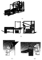
図11のように投影手段として、より好ましくは、視覚認識センサとして小型化のために、高輝度光源とフォトマスクと投影レンズを直列に配置したことを特徴とし、高輝度光源としてはそれぞれの駆動電源部と接続した図11(a)あるいは(b)のような高輝度LEDまたは(d)のようなメタルハライドランプ、図示しないキセノンフラッシュランプ、(c)のような無電極プラズマ光源(LIFI光源)等を用いる。
LEDを用いるときは特に、LEDを1個または複数個をリング状に配置し、それぞれのLEDから放射される光束が効率よくマスクを通過し投影レンズに入射するようにボールレンズをLEDの発光面の近く、なおかつレンズのレンズの中心にむけ少しシフトした配置にすることを採用するとよい。
LEDの駆動部はそれ自体の電源と、カメラの撮像タイミングにあわせてストロボ発光させるための制御部を持つことが好ましい。好ましくはストロボ制御用の外部への信号が用意されているカメラを使用し、撮象タイミングに合わせてLED駆動電源部にトリガー信号を送り発光中に撮像するとよい。
光源の指向性により、指向性がない光源の場合は図11(c)あるいは(d)のような集光ミラー、好ましくは放物面鏡で光源を覆うよう配置してフォトマスクと投影レンズに入る光束を増加させてもよい。あるいは集光用のレンズを光源とフォトマスクの間に配置してもよい。
光源や光源駆動電源部は熱を持ちやすいので、放熱を行うため光源の周囲に冷却用のフィンやファンを取り付け外気を通過させ放熱するとよい。
好ましくは高輝度LEDであればカメラの撮像タイミングに合わせて点灯制御する制御部、電源部を組み合わせると後述するパターン光の抽出において好ましい。[light source]
As shown in FIG. 11, as a projection means, more preferably, as a visual recognition sensor, a high-intensity light source, a photomask, and a projection lens are arranged in series for miniaturization. 11 (a) or 11 (b) connected to a power supply unit, or a metal halide lamp as shown in FIG. 11 (d), a xenon flash lamp (not shown), an electrodeless plasma light source (LIFI light source) as shown in FIG. Etc. are used.
In particular, when using LEDs, one or more LEDs are arranged in a ring shape, and the ball lens is placed on the light emitting surface of the LED so that the light emitted from each LED efficiently passes through the mask and enters the projection lens. It is advisable to adopt an arrangement that is close to the center of the lens and slightly shifted toward the center of the lens.
The LED drive section preferably has its own power supply and a control section for causing strobe light emission in accordance with the imaging timing of the camera. Preferably, a camera having an external signal for strobe control is used, and a trigger signal is sent to the LED drive power supply unit in accordance with the imaging timing to capture an image during light emission.
If the light source has no directivity due to the directivity of the light source, it is arranged so as to cover the light source with a condensing mirror, preferably a parabolic mirror as shown in FIG. The incoming light flux may be increased. Or you may arrange | position the lens for condensing between a light source and a photomask.
Since the light source and the light source drive power supply section are likely to have heat, a cooling fin or fan is attached around the light source to dissipate the heat by passing outside air in order to dissipate heat.
Preferably, a high-intensity LED is combined with a control unit that performs lighting control in accordance with the imaging timing of the camera and a power source unit in extracting pattern light described later.
[フォトマスク]
フォトマスクは遮光部と透過部からなるペンローズ・タイリングパターンであり、例えばガラス基板にクロム蒸着したものを投影レンズを経て投光する。フォトマスクは耐熱性があるので上記光源等を用いて熱が発生しても問題がない。
熱等の問題が無い場合は簡便のためたとえば市販の35ミリフィルムカメラとスライドフィルムにて印刷したPTを撮像し、現像処理したスライドをフォトマスクの代わりにしてもよい。
[パターン]
非周期パターンのペンローズ・タイリングにはファットとシンの組合せの他に、ダートとカイトと呼ばれる二種類で平面充填されるものがある。
画像処理において表面に投影されたセルをテンプレートとして取り出しメモリに保存するとき、そのテンプレートのサイズは小さいほうが、処理の高速化のために良い。そのためシンプルなタイル、セル形状であるファットとシンの組合せによるペンローズタイリングがより好ましい。
[セル、境界]
蒸着するパターンはCADデータとして製作する。ペンローズ・タイリングのセルの境界線部と内部のいずれを遮光部にしてもよい。実際には背景、パターン光のワークの反射強度の度合いでコントラストに違いがでるため境界部が遮光部ものと、透過部であるものの2種製作して選択可能にするとよい。
[原点マーカ]
マスクにはペンローズ・タイリングとそれ以外にも投影する際の基準点を示す原点座標マーカーを中央付近に配置するとよい。
これにより三次元形状計測装置の計測原点が、カメラからの指定距離離れて、かつ前記原点座標マーカーが反射している点として、例えばロボットシステムに取り付けた後でもわかるようになる。計測が基準面上でないような空間内でおこなわれるときでも座標値が把握しやすい。センサ自体の座標系とロボットの座標系とを合わせたり座標変換するとき簡便に行える利点がある。[Photomask]
The photomask is a Penrose tiling pattern composed of a light-shielding part and a transmission part. For example, a chrome deposited on a glass substrate is projected through a projection lens. Since the photomask has heat resistance, there is no problem even if heat is generated using the light source or the like.
If there is no problem such as heat, for example, a PT printed on a commercially available 35 mm film camera and slide film may be imaged and the developed slide may be used instead of the photomask for convenience.
[pattern]
In addition to the combination of fat and thin, there are two types of non-periodic Penrose tilings, called dirt and kite, which are flat-filled.
In the image processing, when a cell projected on the surface is taken out as a template and stored in a memory, a smaller template size is better for speeding up the processing. Therefore, Penrose tiling with a combination of a simple tile and a cell-shaped fat and thin is more preferable.
[Cell, border]
The pattern to be deposited is produced as CAD data. Either the boundary or the inside of the cell line of the Penrose tiling may be used as the light shielding part. Actually, since the contrast varies depending on the degree of reflection intensity of the background and pattern light workpiece, it is preferable that the boundary portion is made of a light shielding portion and a transmission portion so that the selection can be made.
[Origin marker]
It is preferable to place an origin coordinate marker indicating a reference point for projection in addition to Penrose tiling and other points near the center.
As a result, the measurement origin of the three-dimensional shape measurement apparatus can be recognized as a point that is separated by a specified distance from the camera and the origin coordinate marker is reflected, for example, after being attached to the robot system. Even when the measurement is performed in a space that is not on the reference plane, the coordinate values are easy to grasp. There is an advantage that it can be easily performed when the coordinate system of the sensor itself and the coordinate system of the robot are matched or coordinate-transformed.
[投影レンズ]
フォトマスクと投影レンズの位置関係は投影レンズが計測物体からの実像が結像する位置にフォトマスクを配置する。
投影レンズの仕様は明るく、収差が少ないものがこのましい。
レンズのイメージサークルがフォトマスクより大きければレンズの焦点距離、フォトマスクの有効サイズ、作動距離と計測領域での視野は次の計算式の関係がある。
投影レンズの絞りを開放にしてパターンをワークに投影する場合において、ワークの位置が焦点から遠ざかるとパターンがぼやける。またカメラに取り付けた撮像レンズも同様に焦点が合わなくなる。このような場合であってもPTはぼやけながら異なるパターンを表現するのでなめらかな表面を計測する計測領域とくにカメラの奥行き方向の領域を拡大するため好ましい。[Projection lens]
As for the positional relationship between the photomask and the projection lens, the photomask is arranged at a position where the projection lens forms a real image from the measurement object.
Projection lens specifications are bright and have few aberrations.
If the image circle of the lens is larger than the photomask, the focal length of the lens, the effective size of the photomask, the working distance, and the field of view in the measurement area have the following relationship.
When projecting a pattern onto a work with the projection lens aperture open, the pattern becomes blurred as the work position moves away from the focal point. Similarly, the imaging lens attached to the camera is out of focus. Even in such a case, PT expresses a different pattern while being blurred, so it is preferable to enlarge a measurement region for measuring a smooth surface, particularly a region in the depth direction of the camera.
[カメラ]
カメラは撮像素子により画像を得ること、コンピュータと通信して画像データを転送すること、制御装置と通信して撮像タイミングを制御するものを使用する。
撮像素子としてはCCD(電荷結合素子)、CMOSなどがある。コンピュータとの通信手段はカメラリンク、USB、Firewire(IEEE1394)、GIG−E等の通信規格による画像データの通信を行うデジタルカメラもしくはNTSCなどのアナログカメラを使用する。ロボットの近傍に配置するカメラはノイズの影響を排除するためにはデジタルカメラの仕様が好ましい。高速に多数の画像を撮像するときはカメラリンクが好ましい。カメラの通信形態によってはパソコンにフレームグラバーボードを接続し、グラバーボードにカメラからの画像データを格納するようにする(カメラリンクやアナログカメラの場合)。また直接カメラを接続できる画像処理ユニット等を用いても良い。[camera]
A camera is used that obtains an image by an image sensor, communicates with a computer to transfer image data, and communicates with a control device to control an imaging timing.
Examples of the image sensor include a CCD (charge coupled device) and a CMOS. As a means for communication with a computer, a digital camera or an analog camera such as NTSC that communicates image data according to a communication standard such as camera link, USB, Firewire (IEEE 1394), or GIG-E is used. The camera arranged in the vicinity of the robot preferably has a digital camera specification in order to eliminate the influence of noise. Camera links are preferable when capturing a large number of images at high speed. Depending on the communication mode of the camera, a frame grabber board is connected to the personal computer, and image data from the camera is stored on the grabber board (in the case of a camera link or analog camera). An image processing unit or the like that can be directly connected to a camera may also be used.
[ステレオカメラ]
三次元形状計測装置として用いるカメラは図13のようなステレオカメラが好ましい。2つの撮像素子をもつカメラの間に非周期パターン投光装置が配置されステレオカメラでの形状計測のため、計測物の表面にユニークなパターンを投光する。ここで一体化することは特に必要ではなく、パターンがあたりやすいところであれば計測できる。
また投影装置の位置や向きが変わっても計測誤差への影響が少ない利点がある。
[一体化光源]
一体化の利点は機器のコンパクト化にある。光源とカメラを一体の構成としで一方のカメラを用いず、非周期パターンを光切断法における投光装置として用いても良い。とくにワーク表面の傾きの変化が少なく、並進移動する計測物の計測にはステレオカメラでなくても計測が可能である。[Stereo camera]
The camera used as the three-dimensional shape measuring apparatus is preferably a stereo camera as shown in FIG. An aperiodic pattern projector is disposed between cameras having two image sensors, and a unique pattern is projected onto the surface of a measurement object for shape measurement with a stereo camera. Here, it is not particularly necessary to integrate, and measurement is possible if the pattern is easy to hit.
Further, there is an advantage that the influence on the measurement error is small even if the position and orientation of the projection apparatus are changed.
[Integrated light source]
The advantage of integration is the compactness of the equipment. The light source and the camera may be integrated, and one of the cameras may not be used, and the non-periodic pattern may be used as a light projecting device in the light cutting method. In particular, there is little change in the tilt of the workpiece surface, and it is possible to measure a measuring object moving in translation without using a stereo camera.
[光切断法]
一般に光切断法では小さな一定の幅でレーザー等のスポット光やライン光を照射し、カメラの光軸とライン光等との角度とカメラで計測したライン光等の画像状での反射位置から高さ(奥行き)を計測するがこれとの違いを記載する。
本発明においては例えば図3(b)に示すI1が非周期パターンのフォトマスクと仮定して背後に光源をもち投影レンズで、ユニークなP1点周辺の微少領域内の非周期パターンを投影する投光装置と置き換えると、I2に相当する画像上でQ1からQ2の間の探索範囲を探索すると高さ(奥行き)を計算できる。計測点とQ1、Q2との画像間距離の比は奥行き方向の計測点とZ1、Z2との距離に比例するからである。
過去の光切断法では探索するのはスポット光あるいはライン光であるが、本発明ではワークにワークに投影された非周期パターンの一部領域をテンプレートとする。探索に用いるテンプレートは、計測対象物の計測したい計測点を含む周辺の微少領域であり、探索する画像は、あらかじめz1とz2点の基準平面で撮像して得た平面に非周期パターンを投影した画像である。
計測画像と、近方、あるいは遠方の校正基準面に投影された比較画像上でマッチングされたテンプレートはステレオカメラによる計測の視差に相当するものであるから視差から高さを計算するのと同じ手法でカメラからの高さ、奥行きが計算できる。[Light cutting method]
In general, the light cutting method irradiates a spot light such as a laser or line light with a small constant width, and increases the angle between the optical axis of the camera and the line light, etc., and the reflection position in the image form such as the line light measured by the camera. Measure the depth (depth), but describe the difference.
In rice projection lens the light source behind assuming for example I 1 shown in FIG. 3 (b) and photomask aperiodic pattern in the present invention, to project the non-periodic pattern of small area near unique point P1 replacing the light projecting device can be calculated when searching the search range between Q 1 Q 2 'on the image corresponding to the I 2 height (depth). This is because the ratio of the inter-image distance between the measurement point and Q 1 and Q 2 is proportional to the distance between the measurement point in the depth direction and Z 1 and Z 2 .
In the past light cutting method, the spot light or the line light is searched. In the present invention, a partial region of the aperiodic pattern projected onto the work is used as a template. The template used for the search is a small area around the measurement point of the measurement object to be measured, and the image to be searched is obtained by projecting an aperiodic pattern onto a plane obtained by imaging in advance on the reference plane of z1 and z2 points. It is an image.
The template matched with the measurement image and the comparison image projected on the near or far calibration reference plane corresponds to the parallax of the measurement by the stereo camera, so the same method as calculating the height from the parallax You can calculate the height and depth from the camera.
ここであらかじめ計測領域内に、遠方と近方の校正基準面の間に、段階を設けて別の校正基準面を等間隔に設けた校正用画像を記憶しておく。
カメラの光軸と角度をつけて投影される前記P1点周辺の微少領域内の非周期パターンは、近方の校正基準面から遠方の校正基準面まで1ステップづつ遠方の校正基準面へ投影されるときのカメラ画像上の位置をみると、直線的に移動していく。すなわち全ての点が移動していく。
ここでパターンに線幅を設けているのでその等間隔に段階を設けるさいに、奥行き移動量に対応する前記視差とパターンの前記視差方向の線幅を同じにすれば、以下の条件がなりたつ。
(1)二値化した段階毎に設けた校正用画像と計測ワーク画像のAND画像を取得する
(2)菱形が形成されていればその段階枚に設けた校正用画像の位置の近傍にワーク表面 の計測点がある
(3)菱形が欠損していればその段階枚に設けた校正用画像の位置の近傍にワーク表面の 計測点がある
この基本処理により計測ワーク表面の計測点が3次元形状の高さ階層毎に分類して計測できる。Here, a calibration image in which steps are provided between the far and near calibration reference planes and other calibration reference planes are equidistantly stored in advance in the measurement region.
The non-periodic pattern in the minute area around the P1 point projected at an angle with the optical axis of the camera is projected on the far calibration reference plane from the near calibration reference plane to the far calibration reference plane in one step. If you look at the position on the camera image when moving, it will move linearly. That is, all points move.
Here, since the line width is provided in the pattern, the following conditions are satisfied if the parallax corresponding to the depth movement amount and the line width in the parallax direction of the pattern are made the same in providing steps at equal intervals.
(1) Acquire an AND image of the calibration image and measurement work image provided for each binarized stage. (2) If a diamond is formed, the work is in the vicinity of the position of the calibration image provided on that stage sheet. There is a measurement point on the surface. (3) If the diamond is missing, there is a measurement point on the workpiece surface near the position of the calibration image provided on that stage. It is possible to classify and measure by shape height hierarchy.
一体化によりコンパクトな立体計測システムとなる。
一体化によりカメラ自体の計測座標系、原点をきめることが容易にできる。ロボットシステムに搭載するようなケースでは、一旦搭載するとロボットや他の周辺機器で校正用の基準平面を設置できない場合がある。一体化すれば校正用の計測台を別途設けて、そこで構成を行うことができ、前記原点マーカー等によりロボット搭載したときも、ロボット座標との変換が行いやすい利点がある。
光切断法を用いた場合のメリットはカメラがひとつですむことであるが、ステレオカメラと同等の誤差を期実現するには計測物の高さ変化が計測しやすいように角度をつけて投影させるため、カメラの光軸と投影装置の光軸の間の角度を、ステレオカメラの2つのレンズ光軸間の角度と同等に設けることが望ましい。It becomes a compact three-dimensional measurement system by integration.
Integration makes it easy to determine the measurement coordinate system and origin of the camera itself. In cases where the robot system is mounted on a robot system, once mounted, the reference plane for calibration may not be set by the robot or other peripheral devices. If they are integrated, a calibration measuring stand can be separately provided and configured there, and there is an advantage that conversion to robot coordinates is easy even when the robot is mounted with the origin marker or the like.
The advantage of using the light cutting method is that only one camera is required, but in order to achieve the same error as a stereo camera, it is necessary to project at an angle so that the height change of the measurement object can be easily measured. For this reason, it is desirable that the angle between the optical axis of the camera and the optical axis of the projection device be set equal to the angle between the two lens optical axes of the stereo camera.
[トリガー]
カメラの撮像タイミングは、前記通信手段を経てコンピュータから与えられるトリガー信号により制御される。もしくは撮像タイミングを与えるための他の制御装置からトリガーのタイミングをカメラの入力端子に与えることで撮像を開始、停止してもよい。
前記制御装置は例えばコンベア上を流れるようなワークをエリアカメラで計測するときには一定の間隔をあけて撮像する必要があるが、コンベアにエンコーダーを配置し、エンコーダーからコンベアのベルト移動により発生するパルスを制御装置でカウントし、既定の回数をカウントアップしたときカメラにトリガー信号を送信し一回の撮像を行いデータを転送する。これを繰り返すことで定間隔の撮像するようにしてもよい。制御装置としてはPLC(プログラマブル・ロジック・コントローラ、シーケンサ)などを用いると良い。[trigger]
The imaging timing of the camera is controlled by a trigger signal given from a computer via the communication means. Alternatively, imaging may be started and stopped by giving a trigger timing to the input terminal of the camera from another control device for giving imaging timing.
For example, the control device needs to take an image with a certain interval when measuring a workpiece flowing on the conveyor with an area camera. An encoder is arranged on the conveyor, and pulses generated by the belt movement of the conveyor from the encoder are generated. Counting is performed by the control device, and when the predetermined number of times is counted up, a trigger signal is transmitted to the camera to perform one-time imaging and transfer data. By repeating this, imaging at regular intervals may be performed. A PLC (programmable logic controller, sequencer) or the like may be used as the control device.
[カメラの像面サイズ]
図14のように撮像素子の像面サイズと画素数は計測する領域サイズと、テンプレートのサイズから決める。
視野をWFOV、作動距離をWD、撮像レンズの焦点距離をfとすると
撮像素子の像面サイズはWFOV×f/WDとなる。
「カメラ解像度」
カメラの画素数は、要求誤差から決める。1ピクセルの像面サイズに対応する物体面サイズが要求誤差の基準になる。カメラ座標系を図14のようにXYZ軸を設定した場合、XY方向は画像1ピクセル以下の誤差があると設定する。Z方向の誤差はステレオカメラの双眼距離とwdの比を前記1ピクセル当たりの誤差に乗算した値がおおよその計測誤差であると設定する。
[テンプレートサイズ]
非周期パターンのサイズはテンプレートのサイズから決定する。テンプレートがユニークになるときのM×Nピクセルの画像領域に対応する。作動距離における物体面上でのサイズはm×n(mm)である。探索領域の面積によりこれに含まれる好ましいセル数は変化するが、探索の正確性を期待するときはセル数を多くする。高速化のため計算量を減らすときはセル数を小さくする。
このときM×Nピクセルのでセルの内部と境界部の区別がつく程度のサイズが必要なことはいうまでもない。
前記投光装置から投影されるパターンがカラーパターンである場合は色情報を識別するためカラーカメラを用いることが好ましい。
前記投光装置から投影されるパターンがモノクロパターンである場合は高い感度で陰影を計測するためモノクロを用いることが好ましい。[Image size of camera]
As shown in FIG. 14, the image plane size and the number of pixels of the image sensor are determined from the size of the area to be measured and the size of the template.
If the field of view is W FOV , the working distance is WD, and the focal length of the imaging lens is f, the image plane size of the imaging element is W FOV × f / WD.
"Camera resolution"
The number of pixels of the camera is determined from the required error. The object plane size corresponding to the image plane size of 1 pixel is a criterion for the required error. When the XYZ axes are set in the camera coordinate system as shown in FIG. 14, the XY direction is set to have an error of 1 pixel or less in the image. The error in the Z direction is set such that a value obtained by multiplying the error per pixel by the ratio of the binocular distance and wd of the stereo camera is an approximate measurement error.
[Template size]
The size of the aperiodic pattern is determined from the template size. Corresponds to an image area of M × N pixels when the template is unique. The size on the object plane at the working distance is m × n (mm). Although the preferred number of cells included in the search area varies depending on the area of the search area, the number of cells is increased when the accuracy of the search is expected. To reduce the calculation amount for speeding up, the number of cells is reduced.
In this case, it is needless to say that the size is required to distinguish between the inside of the cell and the boundary portion because of M × N pixels.
When the pattern projected from the projector is a color pattern, it is preferable to use a color camera to identify color information.
When the pattern projected from the projector is a monochrome pattern, it is preferable to use monochrome in order to measure a shadow with high sensitivity.
[コンピュータ]
カメラはパソコンあるいは画像処理ユニット等のコンピュータに接続される。
コンピュータはCPU、ストレージ、メモリ等を備え、メモリに格納した画像に対し画像処理に関する演算を行い識別結果をロボットあるいは展開処理装置に送信する。このとき別の制御装置に送信し別の制御装置がロボット動作に必要なデータに変換してロボットに送信してもよい。
[画像処理ユニット]
コンピュータは専用の画像処理を行う画像処理ユニットであってもよい。画像処理ユニットは前記コンピュータと同様の機能をもち、他の制御コントローラと通信する機能をもたせることで、高温作業化での動作が安定しないコンピュータに比較して信頼性が上がる。[Computer]
The camera is connected to a computer such as a personal computer or an image processing unit.
The computer includes a CPU, a storage, a memory, and the like, performs an operation related to image processing on an image stored in the memory, and transmits an identification result to a robot or a development processing device. At this time, the data may be transmitted to another control device, and the other control device may convert the data necessary for the robot operation and transmit the data to the robot.
[Image processing unit]
The computer may be an image processing unit that performs dedicated image processing. The image processing unit has the same function as that of the computer, and has a function of communicating with other control controllers, so that the reliability is improved as compared with a computer whose operation at high temperature operation is not stable.
[一体化の選択肢]
小型の画像処理ユニットを用いてカメラと一体化すると制御部のコンピュータに変わることで制御部の占有領域がなくなりコンパクト化するため好ましい。
このとき画像処理ユニットは、別途統合制御装置からの指令により撮像と画像処理を行い形状計測した結果からの伝送情報を制御装置またはロボットコントローラに送信する。
ステレオカメラで三次元計測する場合、投光装置は一体であっても、別の位置に配置しても良い。
一体にする場合は、光源に高輝度LEDやキセノンフラッシュランプを用いるとよい。LEDは常時点灯しても良いか、通常は投光させず撮像のトリガーと同期して投光することで発熱を押さえられる。同期信号をキセノンフラッシュランプの駆動に用いても良い[Integration options]
It is preferable to integrate the camera with a camera using a small image processing unit, because the area occupied by the control unit is eliminated by changing to a computer of the control unit, thereby reducing the size.
At this time, the image processing unit separately transmits image information and image processing according to a command from the integrated control apparatus, and transmits transmission information from the shape measurement result to the control apparatus or the robot controller.
When three-dimensional measurement is performed with a stereo camera, the light projecting device may be integrated or may be arranged at another position.
When integrated, a high-brightness LED or a xenon flash lamp may be used as the light source. The LED may be always turned on, or normally, the heat generation is suppressed by projecting light in synchronization with an imaging trigger without projecting light. The synchronization signal may be used to drive a xenon flash lamp
[PLC、PC]
前記の画像認識を行うコンピュータ、ロボット、展開装置、周辺機器は、直接的に通信手段を用意してもよい。またの他にこれらを統合的に制御するPLC(シーケンサ)あるいは制御用パソコンと接続してもよい
[ロボット][周辺機器][展開装置]
ロボットまたは展開装置は前記コンピュータからの画像認識データをもとに周辺機器と協調してハンドリングを行う。接続方法については発明者による特許文献5に記載の方法でおこなうとよい。
以下では本発明の実施例を説明するが、本発明は実施例によって限定される物ではない。[PLC, PC]
The computer, the robot, the developing device, and the peripheral device that perform the image recognition may directly provide communication means. In addition, it may be connected to a PLC (sequencer) or a control personal computer that controls these in an integrated manner [robot] [peripheral equipment] [deployment device]
The robot or the developing device performs handling in cooperation with peripheral devices based on the image recognition data from the computer. About a connection method, it is good to carry out by the method of
Examples of the present invention will be described below, but the present invention is not limited to the examples.
実施例1は近方校正基準面での観察視野が780×540mm、作動距離が1300から1500mmで動作する洗濯されたタオル等の布類のハンドリングシステムに関する。
過去の発明者らの図9に記載の展開装置においてタオルの四隅の端部の内一端をスライダロボットハンドが把持し、把持した端部の長辺側の相手方付近を保持しつつ斜め上方に引き出すことで把持した端部の短辺状の相手方の端部周辺が展開されて吊り下げられる。前記端部周辺を本発明による投影装置が表面に非周期パターン光を投影できるようにする。投影装置はカメラと一体型として別途に投光装置のための場所をなくしコンパクトにした。本発明による三次元計測装置からの布端部形状の計測結果から布端の把持に必要な角部の形状情報から短辺を把持する。そして短辺の両端をたぐり出して展開しコンベアに投入するものである。
撮像装置はステレオカメラを用いて図13に記載したようなステレオカメラからなる視覚センサを使用する。レンズ光軸を平行に配置するあおり光学系のステレオカメラではソフトウェアでの遠近歪みの除去が不要になるため好ましい。
また図13(a)から(c)に記載した調整機構を持てば対応点付けを画像の水平方向に行えるので好ましい。ステレオカメラの撮像素子間の間隔は500mmである。
撮像レンズはイメージサークルが約10mm、焦点距離f=8mmのレンズを採用した。The first embodiment relates to a handling system for a cloth such as a washed towel which operates at an observation field of view of 780 × 540 mm on a near calibration reference plane and a working distance of 1300 to 1500 mm.
In the developing device shown in FIG. 9 of the past inventors, the slider robot hand grips the inner end of the four corners of the towel, and pulls it out obliquely while holding the vicinity of the counterpart on the long side of the gripped end. As a result, the periphery of the opposite end of the short side of the gripped end is developed and suspended. The projection device according to the present invention can project aperiodic pattern light on the surface around the end portion. The projection device is integrated with the camera, making it compact by eliminating the space for the projector. The short side is grasped from the shape information of the corner necessary for grasping the cloth edge from the measurement result of the cloth edge shape from the three-dimensional measuring apparatus according to the present invention. Then, both ends of the short side are squeezed out and unfolded and put into a conveyor.
The imaging device uses a visual sensor composed of a stereo camera as shown in FIG. 13 using a stereo camera. A tilt optical system stereo camera in which the lens optical axes are arranged in parallel is preferable because it eliminates the need to remove perspective distortion by software.
In addition, it is preferable to have the adjusting mechanism described in FIGS. 13A to 13C because the corresponding scoring can be performed in the horizontal direction of the image. The interval between the imaging elements of the stereo camera is 500 mm.
As the imaging lens, a lens having an image circle of about 10 mm and a focal length f = 8 mm was employed.
予め計測範囲の最遠方及び最近傍の二つの平面を規定する。二つの平面は平行である。平面は基準画像側の撮像レンズに鉛直に配置する。
あおり光学系であれば二つの撮像レンズは平行に配置される。計測領域でステレオ計測が可能になる左右のカメラの視野がオーバーラップする領域が増えるので実効精度が増す利点がある。
校正方法の一例として図示しない近方平面には正方格子の交点にドットを配置したような校正パターンあるいは市松模様のパターンを一時的に配置する。近い方平面を左右のカメラで撮像したとき同一の画像になるようにあおり系カメラを調整する。もしくは周辺の不要な部分をカットして計測する部位を選択することで選択後の画像が同じになるようにする。
本実施例で使用したあおり光学系カメラは特許文献4,5に記載した左右方向のシフト調整と、上下方向のライズ調整、回転方向のローテーション調整の3つの調整機構付カメラを採用した。本発明においては一方またはいずれかのカメラをシフト可能にすればよいが、ここでは両方のカメラをシフト可能にして近方基準校正面で双方のシフト量が同じになるよう調整した。
このような校正をもつあおり光学系のカメラとするためには、基板に撮像素子が搭載された状態でボードレベルで提供されるボードカメラを使用することが好ましい。
ボードカメラはUSB2.0通信規格のデジタルカメラを使用したが前記の別途通信規格のものでもよい。像面サイズは4.8mm×3.6mm、解像度は640×480ピクセルである。
このような調整ができないカメラ配置の時は、一つの校正基準面上で画像処理により同一画像になるようなアフィン変換を行い、その変換パラメータをもって変換した画像により処理を行う。Two planes that are the farthest and nearest to the measurement range are defined in advance. The two planes are parallel. The plane is arranged vertically on the imaging lens on the reference image side.
In the tilt optical system, the two imaging lenses are arranged in parallel. There is an advantage that the effective accuracy increases because the area where the fields of view of the left and right cameras that allow stereo measurement in the measurement area overlap increases.
As an example of the calibration method, a calibration pattern or a checkered pattern in which dots are arranged at intersections of a square lattice is temporarily arranged on a near plane (not shown). The tilt camera is adjusted so that when the near plane is captured by the left and right cameras, the same image is obtained. Alternatively, by cutting unnecessary portions around the periphery and selecting a part to be measured, the images after selection are made the same.
The tilt optical system camera used in the present embodiment employs a camera with three adjustment mechanisms described in
In order to obtain a tilt optical system camera having such a calibration, it is preferable to use a board camera provided at a board level with an image sensor mounted on a substrate.
The board camera uses a USB 2.0 communication standard digital camera, but it may be a separate communication standard. The image plane size is 4.8 mm × 3.6 mm, and the resolution is 640 × 480 pixels.
When the camera cannot be adjusted in this way, affine transformation is performed so that the same image is obtained by image processing on one calibration reference plane, and processing is performed using the image converted with the conversion parameter.
[最大探索範長]
ドットパターンを最近傍の平面に移動したときの左右カメラのドット出現位置の差分のピクセル数を最大探索長とする。
本実施例の基本条件をまとめると、作動距離1300〜1500mm、近方校正基準面での視野780mm、遠方校正基準面での視野900mm、双眼距離500mm、1ピクセル当たりの近方校正基準面での該当サイズが1.21mmであるから一方のカメラを基準画像とするとき参照画像が探索するピクセルサイズは、基準画像から取り出した、画像上の計測点を含む微少領域の基準点位置から、視差出現方向に約52ピクセル移動した位置の範囲内となる。あおり光学系の場合、レンズ収差がなければ水平方向のみのマッチングを行えばよいが、収差を考え数ピクセルの幅をもたせた長方形の探索範囲を設定する。
前記探索範囲から得た、基準画像上での計測点と参照画像上での計測点入りを結んだエピポーララインの長さから高さは計算できる。近方基準校正面とカメラの計測座標系の位置関係は既知である。遠方の校正基準面上に計測点があるときの視差が52ピクセルなので、近方、遠方の校正基準面間の200mmの距離の間にある計測点の視差をKとすると(K/52)×200が近方基準面から遠方にむけた高さである。(特許文献5参照)
本発明における光学系ではXY平面上のサイズは計測物体のカメラからの距離により、同一の大きさであっても、距離により画像上のサイズは比例変化する。カメラ座標原点からのXY方向のスケールは前記数式によって得られる計測点の高さから比例計算することでXY方向のサイズは計算できる。たとえば近方校正基準面で780mmの視野は遠方校正基準面では900mmのサイズとなるから、その比率で原点からの距離を補正するとX,Yの座標値が計算できる。
なおこれらは前記同様あおり光学系を用いた手法の利点であるが、それ以外の場合でもアフィン変換等の変換を行えば計算による補正をもちいて計測しても良い。
ステレオカメラでの三次元計測で前記特許文献5ではあらかじめ決めたドットパターンを最初に探すが、本発明では以下の方法がこのましい。[Maximum search range length]
The number of pixels of the difference between the dot appearance positions of the left and right cameras when the dot pattern is moved to the nearest plane is set as the maximum search length.
To summarize the basic conditions of this embodiment, the working distance is 1300 to 1500 mm, the visual field is 780 mm at the near calibration reference plane, the visual field is 900 mm at the far calibration reference plane, the binocular distance is 500 mm, and the near calibration reference plane per pixel is Since the corresponding size is 1.21 mm, the pixel size searched by the reference image when one camera is used as the standard image is the appearance of the parallax from the standard point position of the micro area including the measurement point on the image extracted from the standard image. It is within the range of the position moved about 52 pixels in the direction. In the case of a tilt optical system, if there is no lens aberration, matching only in the horizontal direction may be performed, but a rectangular search range having a width of several pixels is set in consideration of aberration.
From the search range, the height can be calculated from the length of the epipolar line connecting the measurement points on the standard image and the measurement points on the reference image. The positional relationship between the near reference calibration surface and the measurement coordinate system of the camera is known. Since the parallax when the measurement point is on the far calibration reference plane is 52 pixels, if the parallax of the measurement point between the 200 mm distance between the near and far calibration reference planes is K (K / 52) × 200 is the height away from the near reference plane. (See Patent Document 5)
In the optical system of the present invention, even if the size on the XY plane is the same size depending on the distance of the measurement object from the camera, the size on the image varies proportionally with the distance. The size in the XY direction can be calculated by proportionally calculating the scale in the XY direction from the camera coordinate origin from the height of the measurement point obtained by the above formula. For example, a field of view of 780 mm on the near calibration reference plane has a size of 900 mm on the far calibration reference plane, and therefore the X and Y coordinate values can be calculated by correcting the distance from the origin by the ratio.
These are the advantages of the method using the optical system as described above. However, in other cases, measurement may be performed using correction by calculation if conversion such as affine transformation is performed.
In the above-mentioned
基準画像から計測部位の範囲のなかで三次元形状計測すべき点を識別する。前処理において二値化処理により背景とワーク領域を分離してできる形状について前記特許文献に記載のように、輪郭線を曲率を取得しながらトラッキングして90度に近い鋭角である部分を識別することにより端部把持点の位置を識別できる。
さらに識別した前記端部点につながる短辺上でハンドの把持間隔だけ離れた点(短辺把持点)を識別する
次に同様に長辺上で設定ながさだけは離れた点(把持方向参照点1)または前記短辺把持点から発する、前記短辺把持点と前記端部把持点を結ぶ線の法線上で、前記短辺は時点から設定長さ離れた点(把持方向参照点2)の位置を計測する。特許文献5参照の公知の手法を用いても良い。A point to be measured for the three-dimensional shape is identified in the range of the measurement site from the reference image. As described in the above-mentioned patent document, the shape obtained by separating the background and the work area by binarization processing in the preprocessing is used to track the contour line while acquiring the curvature to identify a portion having an acute angle close to 90 degrees. Thus, the position of the end gripping point can be identified.
Further, a point separated by the hand grip interval (short side grip point) on the short side connected to the identified end point is identified. Next, similarly, a point that is set apart on the long side (grip direction reference point) 1) or on the normal of the line connecting the short side gripping point and the end gripping point, which originates from the short side gripping point, the short side is a point (grip direction reference point 2) that is a set length away from the point in time. Measure the position. You may use the well-known method of the
前処理により決定した基準画像上の計測点について、前記三つの計測点位置と計測点周辺の微少表面エリアをテンプレート画像として記憶する。
テンプレートの形状は(n×m)のピクセルからなる四角形、あるいは十字の形状で校正する。テンプレートのサイズはテンプレートのなかに存在する非周期パターンのセル境界部が複数存在することで対応が可能になる。
このとき計測ワークの表面が図14に示すステレオカメラの三次元計測値を表現するセンサー座標系において、微少領域の法線方向がカメラ方向を向いた(+Z)場合はどのようなテンプレート形状でもよい。
例えばワークの形状変化において前記法線方向が前記方向からX軸回りに回転した場合が多いときは横長の線状に近い四角形にしてもよい。
同様に例えば前記法線方向が前記方向からY軸回りに回転することが多い場合、縦長の線状に近い四角形にしてもよい。
テンプレートサイズは前記エピポーララインの最大探索長以内の対応点づけにおいてユニークさが保てるサイズにする。For the measurement points on the reference image determined by the preprocessing, the three measurement point positions and the minute surface area around the measurement points are stored as a template image.
The template shape is calibrated with a square or cross shape made up of (n × m) pixels. The template size can be dealt with by the presence of a plurality of cell boundary portions of the aperiodic pattern existing in the template.
At this time, in the sensor coordinate system in which the surface of the measurement work expresses the three-dimensional measurement value of the stereo camera shown in FIG. 14, any template shape may be used when the normal direction of the minute region faces the camera direction (+ Z). .
For example, when there are many cases where the normal direction is rotated about the X axis from the direction in the change in the shape of the workpiece, a quadrilateral close to a horizontally long linear shape may be used.
Similarly, for example, when the normal direction often rotates around the Y axis from the direction, a square that is close to a vertically long line may be used.
The template size is set to a size that can maintain uniqueness in matching points within the maximum search length of the epipolar line.
テンプレート部に投影されるパターンはパターンの透過部と遮光部による物体面に投影された像がカメラで識別できるだけのコントラストを与えるように、パターンのサイズを決めた。ここでは0.154mmを一辺のサイズとし、線の太さを0.04mmでファットとシンの2種の菱形のペンローズ・タイリングにより平面充填されたフォトマスクとした。
このときの物体面に投影されるタイリングの像の全ての菱形の一辺の長さは近方基準校正面上で23.1mmである。
前記光学条件では、1ピクセルあたりのこの範囲でパターンを構成するセル(タイル)の一部が複数、3から6つ、もしくはそれ以上含まれることが好ましい。The size of the pattern projected on the template part was determined so that the image projected on the object plane by the transmissive part and the light-shielding part of the pattern gave enough contrast to be identified by the camera. Here, 0.154 mm is set as a side size, the thickness of the line is 0.04 mm, and the photomask is flat-filled with two types of rhombus Penrose tilings of fat and thin.
The length of one side of all the rhombuses in the tiling image projected on the object plane at this time is 23.1 mm on the near reference calibration plane.
In the optical condition, it is preferable that a part of cells (tiles) constituting a pattern in this range per pixel include a plurality, 3 to 6, or more.
本実施例に因れば最大探索長はピクセル数として52ピクセル以上になり、投影面での画素1ピクセルの一片長さが1.21mmである。前記一辺の近方校正基準面上のサイズが23.1mmであるのでこれを超えたテンプレートサイズにするには少なくとも一辺が19ピクセルを超える必要がある。一つのセルを完全に覆うピクセル数としてこの2倍ないし3倍の2少なくとも一辺の画素数をもつテンプレートサイズにすれば前記最大探索範囲の52ピクセル間でのマッチングにおいてほぼユニークさを保つことができる。
なお、高速化にためには前処理にて画像の1/nのスケール変換を行いこれにより計測してもよい。
このときは前記投影面での画素1ピクセルの一片長さが1.21mmスケール変換によりn倍するので、同じテンプレートサイズで探索する場合は、より相関値が上がりより正確な計測ができ、あるいはテンプレートサイズをスケール分小さくすればより高速化する。図16の(a)から(g)にはこれまでに述べたサンプル画像の処理の仕方を説明している。According to this embodiment, the maximum search length is 52 pixels or more, and the length of one pixel on the projection plane is 1.21 mm. Since the size of the one side on the near calibration reference plane is 23.1 mm, at least one side needs to exceed 19 pixels in order to obtain a template size exceeding this. If the template size has 2 or 3 times the number of pixels on at least one side as the number of pixels completely covering one cell, the uniqueness can be maintained in matching between the 52 pixels of the maximum search range. .
In order to increase the speed, 1 / n scale conversion of the image may be performed in the preprocessing and the measurement may be performed.
At this time, the length of one pixel on the projection plane is multiplied by n by the 1.21 mm scale conversion. Therefore, when searching with the same template size, the correlation value increases and more accurate measurement can be performed. If the size is reduced by the scale, the speed is increased. FIGS. 16A to 16G illustrate the processing method of the sample image described so far.
前記の対応点付け(テンプレートマッチング)においては公知のサブピクセルでの手法を用いればピクセル間隔以下の単位まで計測誤差を小さくできる。
実施例においてはコンパクト化するためステレオカメラと一体化した投光光源であることが好ましいがこれに限定するものではない。
カメラ位置と計測対象物の表面の位置関係によりカメラに投光されたパターンが写りやすいように、投影装置をカメラから離して配置しても、カメラの校正に影響がない利点があるためである。In the above-described matching (template matching), if a known subpixel method is used, the measurement error can be reduced to a unit equal to or less than the pixel interval.
In the embodiment, a light projecting light source integrated with a stereo camera is preferable for compactness, but the present invention is not limited to this.
This is because even if the projection device is placed away from the camera so that the pattern projected on the camera can be easily captured due to the positional relationship between the camera position and the surface of the measurement object, there is an advantage that the calibration of the camera is not affected. .
計測物に投影したパターンのみを取得する前処理方法が特許文献5では用いられた。
静止した計測物にパターン投影した画像と、しない画像の2種類撮像し、その差分をとることでパターン光のみを抽出し、2値化することでパターン光の反射部のみを抽出する方法である。コンピュータとプロジェクタを接続し、さらにカメラの撮像トリガも制御するようにすれば、まず非周期パターンを投影した画像を撮像し、その次にパターン光の投影を中断して計測物を撮像することにより前記差分画像を取得することができる。これによりよりロバストなパターン光の抽出ができる。
前記パターン光の差分画像取得のとき撮像回数が増えることにより計測時間が多くなる問題があるときは動的閾値法をもちいる。動的閾値法ではパターン投光画像のみを使用する。そのため撮像回数は一回ですむ。撮像したパターン画像のコントラストが強いときは本手法が有効である。処理プロセスは以下の通りである。
(1) パターン付ワーク画像取得とメモリに画像1として保存
(2) 平均化フィルタをかけメモリに画像2として保存
(3) 画像2から画像1を差分処理しメモリに画像3として保存
(4) 画像3を二値化処理してパターン光を抽出In
This is a method of picking up only two types of pattern light by taking two types of images, a pattern projected onto a stationary measurement object and an image without a pattern, and extracting the difference between them, and extracting only the pattern light reflection part by binarization. . If a computer and a projector are connected and the imaging trigger of the camera is also controlled, an image obtained by projecting an aperiodic pattern is first captured, and then the projection of pattern light is interrupted to capture the measurement object. The difference image can be acquired. As a result, more robust pattern light can be extracted.
When there is a problem that the measurement time increases due to an increase in the number of times of imaging when acquiring the difference image of the pattern light, the dynamic threshold method is used. In the dynamic threshold method, only a pattern projection image is used. Therefore, the number of times of imaging is one. This method is effective when the contrast of the captured pattern image is strong. The processing process is as follows.
(1) Acquisition of patterned work image and saving as
第2の実施例は洗濯前あるいは洗濯後において種別毎に分類・カウントを行うシステムである。ここでは山積みの状態でコンベアに載せられたシーツ、枕カバー、布団カバーなどの洗濯物を一枚ずつ持って取りだし、引き上げるときの荷重変化による種別判定の他に、引き上げた後にコンベアに受け渡し、コンベアを通過するときにその一枚の洗濯物の体積を計測することでも分類を行う。またその際、カメラ等により洗濯物の色を識別する。
これらの荷重変化、イナーシャ変化等の、力をベースにした分類判定と視覚をベースにした分類判定は、アイテム毎にどの分類判定に重みを置くかをあらかじめ決めておき、各分類判定における確からしさの数値を加算し総合判定する。あるいはそれぞれの計測データについてベクトル情報として持っておき、アイテム毎の教示データとのベクトル間距離で判定する。
力による計測には上昇時の荷重変化を計測するため短いサンプリングレートでロードセルを用いて計測する。ロードセルの計測値が正確になるよう、ピックアッ・プルアームには平行四辺形のリンク機溝である、ロバーバル機構を配置して、ワークの位置によって計測値が変わらないようにしている。
このようにあらかじめ力をベースにした判定でアイテム種類がわかる場合はそれだけで分類する。重さの変化がなくわかりにくいアイテムの場合はコンベア上のカメラで計測して総合判定する。視覚的に色の違いなど、判定可能な計測項目で正確にわかるときはそれで判定する。
さらにそれでもわからないとき、このような手法において、本発明の投影装置及び三次元計測装置では、コンベア上を通過するアイテムを定間隔で撮像し、ステレオ計測する。このような高速に移動するコンベア上で撮像する場合は、ワークの存在位置を識別して三次元形状を計測する計測点を決定しても良いが、このましくはあらかじめ等間隔で計測点をきめておきその点の高さを単純に加算していけば概略の体積が高速に計算できる。
体積がわかれば重量データと合わせて比重等がわかるので重量だけでは分類できないものも分類対応が可能になる。The second embodiment is a system for performing classification / counting for each type before or after washing. Here, the sheets, pillow covers, and futon covers that are placed on the conveyor in a piled state are taken out one by one, and in addition to the type determination based on the load change when lifting, they are transferred to the conveyor after being lifted. Classification is also performed by measuring the volume of one piece of laundry when passing through. At that time, the color of the laundry is identified by a camera or the like.
The classification judgment based on force and the classification judgment based on vision, such as load change and inertia change, determine in advance which classification judgment is to be weighted for each item, and the probability in each classification judgment. Add the numerical value of to make a comprehensive judgment. Alternatively, each measurement data is held as vector information, and the determination is made based on the distance between vectors with the teaching data for each item.
For measurement by force, the load cell is measured at a short sampling rate in order to measure the load change at the time of ascent. In order to make the measured value of the load cell accurate, the pick-up / pull arm is provided with a robot mechanism, which is a parallelogram link machine groove, so that the measured value does not change depending on the position of the workpiece.
In this way, if the item type can be known in advance based on the determination based on the force, it is classified based on that alone. For items that do not change in weight and are difficult to understand, comprehensive judgment is made by measuring with a camera on the conveyor. When it is possible to accurately determine the measurement items that can be visually determined, such as the difference in color, the determination is made.
Furthermore, when it is still unclear, in such a method, the projection device and the three-dimensional measurement device according to the present invention image the items passing on the conveyor at regular intervals and perform stereo measurement. When imaging on a conveyor that moves at such a high speed, it is possible to determine the measurement points for measuring the three-dimensional shape by identifying the position of the workpiece. If you simply add the heights of the points, the approximate volume can be calculated at high speed.
If the volume is known, the specific gravity and the like can be known together with the weight data, so that it is possible to classify those that cannot be classified by weight alone.
コンベア上のワークは一定の間隔移動したとき撮像し、画像を記憶するコンピュータに送信する。ここではカメラリンクのデジタルカメラを用いた。ステレオカメラで光軸を平行にして配置してあおり光学系の計測手法で計測した。校正は実施例1と同様に行う遠・近方両面でのパターン画像を取得して参照画像での探索範囲を設定している。基準画像を右カメラ、参照画像を左カメラで取得した。
コンピュータにはカメラリンクデジタルカメラと接続するためのフレームグラバをもち、カメラからの画像情報が格納する。撮像する計測点はコンベア上でXY方向で間隔一定にした格子の交点を基準画像上に計測点として設定し、その計測点を含む周辺領域をテンプレートとして参照画像上でマッチングを行う。図15に示すドットは計測点の位置と、計測した高さを濃淡であらわしたサンプル結果である。
コンベア上は高さデータが0として出力される。各格子領域の体積は計測点の高さに概ね比例するので、計測範囲内の高さデータの和を計算して、換算計数をかければ概略的な体積がわかる。
一枚ずつとりだして計測コンベアに通され、最終的に計測したデータにより判定を行う間、コンベア下流のフラップ上に格納される。判定結果によりフラップしたのスライドコンベア2台が各アイテム毎の分類かごに向けて、落下または排出できるようにコンベアを移動し、回転方向をかごに向け回るようコンベアを回転させることで分類が可能になる。The work on the conveyor is picked up when it is moved at a fixed interval, and transmitted to a computer that stores the image. Here, a camera-link digital camera was used. A stereo camera was used with the optical axes set parallel to each other, and measurements were taken using an optical measurement system. Calibration is performed in the same manner as in the first embodiment, and pattern images on both the far and near sides are acquired and the search range in the reference image is set. The reference image was acquired with the right camera and the reference image with the left camera.
The computer has a frame grabber for connecting to a camera link digital camera, and stores image information from the camera. The measurement points to be imaged are set as intersections of lattices with a constant interval in the XY direction on the conveyor as measurement points on the reference image, and matching is performed on the reference image using a peripheral region including the measurement points as a template. The dots shown in FIG. 15 are sample results in which the position of the measurement point and the measured height are represented by shading.
The height data is output as 0 on the conveyor. Since the volume of each grid area is approximately proportional to the height of the measurement point, the approximate volume can be obtained by calculating the sum of the height data in the measurement range and applying a conversion count.
Each sheet is taken out and passed through the measurement conveyor, and is stored on the flap downstream of the conveyor while the determination is made based on the finally measured data. Classification is possible by moving the conveyor so that the two slide conveyors flapped according to the judgment result can be dropped or ejected toward the classification car for each item, and rotating the conveyor so that the rotation direction is directed to the car Become.
本発明は画像認識による後者の手法をよりコンパクト、高速かつ確実におこなうために出来たが、三次元計測の応用可能分野は多岐にわたっており、布のハンドリングのための形状計測技術あるいはロボットハンドリングに限定するものではない。
たとえば建物、人体や工業部品、農産物などの計測も応用分野の一つである。Although the present invention was able to make the latter method by image recognition more compact, faster and more reliable, the applicable fields of 3D measurement are wide-ranging and limited to shape measurement technology for fabric handling or robot handling Not what you want.
For example, measurement of buildings, human bodies, industrial parts, agricultural products, etc. is one of the application fields.
Claims (5)
Priority Applications (1)
| Application Number | Priority Date | Filing Date | Title |
|---|---|---|---|
| JP2011058512A JP2012177671A (en) | 2011-02-27 | 2011-02-27 | Fine aperiodic pattern projection device and method and three-dimensional measuring device using the same |
Applications Claiming Priority (1)
| Application Number | Priority Date | Filing Date | Title |
|---|---|---|---|
| JP2011058512A JP2012177671A (en) | 2011-02-27 | 2011-02-27 | Fine aperiodic pattern projection device and method and three-dimensional measuring device using the same |
Publications (1)
| Publication Number | Publication Date |
|---|---|
| JP2012177671A true JP2012177671A (en) | 2012-09-13 |
Family
ID=46979588
Family Applications (1)
| Application Number | Title | Priority Date | Filing Date |
|---|---|---|---|
| JP2011058512A Withdrawn JP2012177671A (en) | 2011-02-27 | 2011-02-27 | Fine aperiodic pattern projection device and method and three-dimensional measuring device using the same |
Country Status (1)
| Country | Link |
|---|---|
| JP (1) | JP2012177671A (en) |
Cited By (4)
| Publication number | Priority date | Publication date | Assignee | Title |
|---|---|---|---|---|
| JP2016507886A (en) * | 2012-11-29 | 2016-03-10 | コーニンクレッカ フィリップス エヌ ヴェKoninklijke Philips N.V. | Laser apparatus for projecting structured light patterns onto a scene |
| JP2017067758A (en) * | 2015-09-28 | 2017-04-06 | 株式会社リコー | system |
| WO2019117001A1 (en) * | 2017-12-11 | 2019-06-20 | オムロン株式会社 | Image processing device and image processing method |
| JP2019138817A (en) * | 2018-02-14 | 2019-08-22 | オムロン株式会社 | Three-dimensional measuring device, three-dimensional measuring method, and three-dimensional measuring program |
-
2011
- 2011-02-27 JP JP2011058512A patent/JP2012177671A/en not_active Withdrawn
Cited By (9)
| Publication number | Priority date | Publication date | Assignee | Title |
|---|---|---|---|---|
| JP2016507886A (en) * | 2012-11-29 | 2016-03-10 | コーニンクレッカ フィリップス エヌ ヴェKoninklijke Philips N.V. | Laser apparatus for projecting structured light patterns onto a scene |
| US10386178B2 (en) | 2012-11-29 | 2019-08-20 | Philips Photonics Gmbh | Laser device for projecting a structured light pattern onto a scene |
| JP2017067758A (en) * | 2015-09-28 | 2017-04-06 | 株式会社リコー | system |
| US10737391B2 (en) | 2015-09-28 | 2020-08-11 | Ricoh Company, Ltd. | System for capturing an image |
| WO2019117001A1 (en) * | 2017-12-11 | 2019-06-20 | オムロン株式会社 | Image processing device and image processing method |
| JP2019138817A (en) * | 2018-02-14 | 2019-08-22 | オムロン株式会社 | Three-dimensional measuring device, three-dimensional measuring method, and three-dimensional measuring program |
| WO2019159769A1 (en) * | 2018-02-14 | 2019-08-22 | オムロン株式会社 | Three-dimensional measurement apparatus, three-dimensional measurement method and program |
| CN111566440A (en) * | 2018-02-14 | 2020-08-21 | 欧姆龙株式会社 | Three-dimensional measurement device, three-dimensional measurement method, and program |
| US11321860B2 (en) | 2018-02-14 | 2022-05-03 | Omron Corporation | Three-dimensional measurement apparatus, three-dimensional measurement method and non-transitory computer readable medium |
Similar Documents
| Publication | Publication Date | Title |
|---|---|---|
| JP5322206B2 (en) | Three-dimensional shape measuring method and apparatus | |
| US11869139B2 (en) | System and method for three-dimensional scanning and for capturing a bidirectional reflectance distribution function | |
| JP5469216B2 (en) | A device for picking up bulk items by robot | |
| JP2013101045A (en) | Recognition device and recognition method of three-dimensional position posture of article | |
| EP3422955B1 (en) | System and method for assisted 3d scanning | |
| CN108555908A (en) | A kind of identification of stacking workpiece posture and pick-up method based on RGBD cameras | |
| JP5897532B2 (en) | Apparatus and method for picking up articles placed in three-dimensional space by robot | |
| CN103954213B (en) | A kind of method of the measured drawing for analyzing part | |
| WO2006098258A1 (en) | Calibration method for 3-dimensional measurement and 3-dimensional measurement system using the method | |
| CN104976950B (en) | Object space information measuring device and method and image capturing path calculating method | |
| CN103398669A (en) | Multi-axis linkage visual inspection method and equipment used for measuring free-form surface | |
| JP2012177671A (en) | Fine aperiodic pattern projection device and method and three-dimensional measuring device using the same | |
| JP2010256253A (en) | Image capturing device for three-dimensional measurement and method therefor | |
| JP2020012669A (en) | Object inspection device, object inspection system, and method for adjusting inspection position | |
| WO2021012681A1 (en) | Object carrying method applied to carrying robot, and carrying robot thereof | |
| JPWO2020144784A1 (en) | Image processing equipment, work robots, substrate inspection equipment and sample inspection equipment | |
| WO2011074246A1 (en) | Textile article identification device and textile article gripping system | |
| CN114136975A (en) | Intelligent detection system and method for surface defects of microwave bare chip | |
| JP5156972B2 (en) | Position measuring apparatus and position measuring method | |
| US11590657B2 (en) | Image processing device, control method thereof, and program storage medium | |
| AU2020217607B2 (en) | Generation of texture models using a moveable scanner | |
| JP2018146347A (en) | Image processing device, image processing method, and computer program | |
| JP6381262B2 (en) | Information processing apparatus, information processing method, and program | |
| CN109323691A (en) | A kind of positioning system and localization method | |
| JP7154084B2 (en) | Three-dimensional shape measuring device and three-dimensional shape measuring program |
Legal Events
| Date | Code | Title | Description |
|---|---|---|---|
| A300 | Application deemed to be withdrawn because no request for examination was validly filed |
Free format text: JAPANESE INTERMEDIATE CODE: A300 Effective date: 20140513 |