JP2012174377A - Rotary support device, and garden stone lantern - Google Patents
Rotary support device, and garden stone lantern Download PDFInfo
- Publication number
- JP2012174377A JP2012174377A JP2011032750A JP2011032750A JP2012174377A JP 2012174377 A JP2012174377 A JP 2012174377A JP 2011032750 A JP2011032750 A JP 2011032750A JP 2011032750 A JP2011032750 A JP 2011032750A JP 2012174377 A JP2012174377 A JP 2012174377A
- Authority
- JP
- Japan
- Prior art keywords
- flat plate
- shaft member
- candle
- lantern
- rotation support
- Prior art date
- Legal status (The legal status is an assumption and is not a legal conclusion. Google has not performed a legal analysis and makes no representation as to the accuracy of the status listed.)
- Granted
Links
Images


Landscapes
- Rolling Contact Bearings (AREA)
- Arrangement Of Elements, Cooling, Sealing, Or The Like Of Lighting Devices (AREA)
- Non-Portable Lighting Devices Or Systems Thereof (AREA)
- Illuminated Signs And Luminous Advertising (AREA)
Abstract
Description
この発明は、基台や地盤などの基礎に対し、石柱または中空石材で形成される被回転体を回転自在に支持する回転支持装置および該回転支持装置を装備する石製灯籠に関するものである。 The present invention relates to a rotation support device that rotatably supports a rotating body formed of a stone pillar or a hollow stone material with respect to a foundation such as a base or ground, and a stone lantern equipped with the rotation support device.
石材を取り扱う業界では、基台に対し、石柱などの被回転体を回転自在に支持するために、例えば特許文献1に記載された構造が多用されている。すなわち、基台側では、基台の上面中央部に垂直な貫通孔や孔部が形成され、その貫通孔等に軸部材の下方端部が挿入されて軸部材の上方端部が基台上面から上方に立設される。一方、被回転体側では、軸部材の上方端部に対応する凹部が被回転体の底面中央部から本体内部に向かって穿設されている。そして、軸部材の上方端部に対して被回転体の凹部が外嵌され、軸部材の上端(頭部や頂部などとも称される)が凹部の内底面に当接した状態で、被回転体は軸部材を回転中心として回転自在に軸支される。
In the industry that handles stone materials, for example, a structure described in
このように従来技術では、軸部材の上端の1点で軸支する構造であるため、軸部材の外径に対して凹部の内径が少しでも大きくなると、回転中に被回転体がふらつき、被回転体の下方端部が軸部材や基台と衝突して欠けや割れなどが発生することがあった。また、軸部材に対応して被回転体に凹部を正確に穿設する必要があり、凹部の位置が所望位置からずれてしまうと、それを修正することが不可能である。したがって、上記従来技術の適用範囲は、重心位置を比較的容易に見つけ出すことができ、しかも重心位置に対応する底面中央部に凹部を高精度に穿設することができる被回転体に限定されており、汎用性を欠けていた。例えば特許文献2に記載の石製灯籠では前面に開口部を設けた中空石材の内部にロウソク立てを配置しているが、このような中空石材を用いる石製灯籠に対し、上記従来技術をそのまま適用することができなかった。
As described above, in the conventional technology, the shaft member is supported at one point at the upper end of the shaft member. Therefore, if the inner diameter of the concave portion is slightly increased with respect to the outer diameter of the shaft member, the rotating body may be staggered during rotation. In some cases, the lower end portion of the rotating body collides with the shaft member or the base to cause chipping or cracking. In addition, it is necessary to accurately drill the recess in the rotated body corresponding to the shaft member, and if the position of the recess deviates from the desired position, it is impossible to correct it. Therefore, the range of application of the above prior art is limited to a rotated body that can relatively easily find the position of the center of gravity and that can accurately drill the recess at the center of the bottom surface corresponding to the position of the center of gravity. And lacked versatility. For example, in the stone lantern described in
この発明は上記課題に鑑みなされたものであり、石柱または中空石材で形成される被回転体を安定して回転させることができ、しかも優れた汎用性を有する回転支持装置および当該回転支持装置を用いていた石製灯籠を提供することを目的とする。 The present invention has been made in view of the above problems, and can provide a rotation support device that can stably rotate a rotating body formed of a stone pillar or a hollow stone material, and has excellent versatility, and the rotation support device. The purpose is to provide the stone lanterns used.
この発明にかかる回転支持装置の第1態様は、基台や地盤などの基礎に対し、石柱または中空石材で形成される被回転体を回転自在に支持する回転支持装置であって、上記目的を達成するため、下方端部が基礎に固定されて中央部および上方端部が基礎から上方に突出する軸部材と、平板中央部が軸部材の中央部に固定されるとともに平板周縁部が平板中央部から水平方向に延びる第1平板と、被回転体を支持する上面を有し、下面を第1平板の上面と平行に対向した状態で軸部材の上方端部に対して回転自在に軸支される第2平板と、第1平板と第2平板で挟まれる3個以上の球体とを備え、第1平板および第2平板のうちの一方の平板では、他方の平板と対向する面に凹部が形成され、球体を転動自在に収容することを特徴としている。 A first aspect of a rotation support device according to the present invention is a rotation support device that rotatably supports a rotating body formed of a stone pillar or a hollow stone material with respect to a foundation such as a base or a ground, and has the above object. To achieve this, a shaft member whose lower end is fixed to the foundation and whose center and upper end protrude upward from the foundation, a flat plate central portion is fixed to the central portion of the shaft member, and a flat plate periphery is a flat plate center A first flat plate extending in a horizontal direction from the portion, and an upper surface that supports the rotating body, and the lower surface is pivotally supported with respect to the upper end of the shaft member in a state of facing the upper surface of the first flat plate in parallel. A second flat plate and three or more spheres sandwiched between the first flat plate and the second flat plate, and in one of the first flat plate and the second flat plate, a recess is formed on a surface facing the other flat plate. Is formed, and the sphere is accommodated in a rollable manner.
このように構成された回転支持装置では、軸部材の下方端部が基台や地盤などの基礎に固定された状態で、軸部材の中央部および上方端部が基礎から上方に突出している。そして、軸部材の中央部に対して第1平板が固定され、この第1平板の上面に3個以上の球体が配置され、さらに、これらの球体の上に第2平板が軸部材の上方端部に対して回転自在に軸支されている。そして、これらの球体は第1平板または第2平板に設けられた凹部内で転動可能となっている。したがって、被回転体に対して加工を加えることなく、しかも被回転体が石柱である場合はもちろんのこと中空石材であったとしても、被回転体を第2平板の上面で支持した状態で第2平板は軸部材回りで滑らかに回転する。また、被回転体の重心が軸部材の上方に位置しない場合には被回転体の回転が不安定となるが、この場合、被回転体の重心が軸部材の上方に位置するように第2平板上での被回転体の位置を調整することで容易に回転の安定化を図ることができる。さらに、第1平板および第2平板の間で球体が転がることで被回転体を回転させており、基礎と被回転体とが衝突したり、擦れ合うことがないだけでなく、基礎および被回転体のいずれも回転支持装置と擦れ合うことはなく、基礎や被回転体から粉塵が発生するのを防止することができる。 In the rotation support device configured as described above, the center portion and the upper end portion of the shaft member protrude upward from the foundation in a state where the lower end portion of the shaft member is fixed to the foundation such as the base or the ground. The first flat plate is fixed to the central portion of the shaft member, three or more spheres are disposed on the upper surface of the first flat plate, and the second flat plate is disposed on the upper end of the shaft member. It is rotatably supported with respect to the part. And these spheres can roll in the recessed part provided in the 1st flat plate or the 2nd flat plate. Therefore, the processed object is supported by the upper surface of the second flat plate without any processing on the rotated object, and even if the rotated object is a stone pillar as well as a hollow stone material. The two flat plates rotate smoothly around the shaft member. Further, when the center of gravity of the rotated body is not positioned above the shaft member, the rotation of the rotated body becomes unstable. In this case, the second center is set so that the center of gravity of the rotated body is positioned above the shaft member. It is possible to easily stabilize the rotation by adjusting the position of the rotated body on the flat plate. Furthermore, the rotating body is rotated by rolling the sphere between the first flat plate and the second flat plate so that the foundation and the rotating body do not collide or rub against each other. None of these rub against the rotating support device, and dust can be prevented from being generated from the foundation or the rotated body.
この発明にかかる回転支持装置の第2態様は、基台や地盤などの基礎に対し、石柱または中空石材で形成される被回転体を回転自在に支持する回転支持装置であって、上記目的を達成するため、下面が基礎の上面に固定される第1平板と、下方端部が第1平板の上面中央部に固定されるとともに、上方端部が上方に延びる軸部材と、被回転体を支持する上面を有し、下面を第1平板の上面と平行に対向した状態で軸部材の上方端部に対して回転自在に軸支される第2平板と、第1平板と第2平板で挟まれる3個以上の球体とを備え、第1平板および第2平板のうちの一方の平板では、他方の平板と対向する面に凹部が形成され、球体を転動自在に収容することを特徴としている。 A second aspect of the rotation support device according to the present invention is a rotation support device that rotatably supports a rotating body formed of a stone pillar or a hollow stone material with respect to a base such as a base or a ground, and has the above object. In order to achieve this, a first flat plate whose lower surface is fixed to the upper surface of the foundation, a shaft member whose lower end is fixed to the center of the upper surface of the first flat plate and whose upper end extends upward, and a rotated body are provided. A second flat plate rotatably supported with respect to an upper end portion of the shaft member in a state of having an upper surface to be supported and having the lower surface facing the upper surface of the first flat plate in parallel, and a first flat plate and a second flat plate It comprises three or more spheres to be sandwiched, and one of the first flat plate and the second flat plate has a recess formed on the surface facing the other flat plate, and accommodates the sphere so that it can roll. It is said.
この第2態様の回転支持装置は、基礎に固定された第1平板に対して軸部材が固定される点で、基礎に固定された軸部材に対して第1平板が固定される第1態様と相違しているが、その他の基本構成は第1態様と全く同一である。つまり、第1平板の上面に3個以上の球体が配置され、これらの球体の上に第2平板が軸部材の上方端部に対して回転自在に軸支され、しかも、これらの球体は第1平板または第2平板に設けられた凹部内で転動可能となっている。したがって、第1態様と同様の作用効果が得られる。 The rotation support device according to the second aspect is a first aspect in which the first flat plate is fixed to the shaft member fixed to the foundation in that the shaft member is fixed to the first flat plate fixed to the foundation. However, the other basic configuration is exactly the same as the first mode. That is, three or more spheres are arranged on the upper surface of the first flat plate, and the second flat plate is rotatably supported on these spheres with respect to the upper end portion of the shaft member. It can roll in a recess provided in the first flat plate or the second flat plate. Therefore, the same effect as the first aspect can be obtained.
ここで、凹部の個数などについては任意であるが、例えば軸部材を取り囲むように複数個設けてもよく、また球体と同一個数設ける場合には複数の凹部に球体を1個ずつ収容すればよい。このように軸部材を取り囲むように設けた各凹部に収容された球体で第2平板および被回転体を支持しているため、応力が分散されて被回転体を長時間滑らかに安定して回転させることができる。 Here, the number of recesses and the like is arbitrary, but for example, a plurality of recesses may be provided so as to surround the shaft member. When the same number as the spheres is provided, the spheres may be accommodated one by one in the plurality of recesses. . Since the second flat plate and the rotated body are supported by the spheres accommodated in the recesses provided so as to surround the shaft member in this way, the stress is dispersed and the rotated body rotates smoothly and stably for a long time. Can be made.
また、この発明にかかる石製灯籠は、上記目的を達成するため、石製基台と、前面に第1開口部が設けられるとともに後面に第2開口部が設けられる中空石材と、上記した回転支持装置と同一の構成を有し、石製基台に対し、中空石材を回転自在に支持する回転支持部と、中空石材の内部でロウソクを支持するロウソク支持部とを備え、回転支持部は、第2平板の上面で中空石材を支持し、ロウソク支持部は軸部材の上方端部に設けられることを特徴としている。 In order to achieve the above object, a stone lantern according to the present invention has a stone base, a hollow stone material provided with a first opening on the front surface and a second opening on the rear surface, and the rotation described above. It has the same structure as the support device, and includes a rotation support part that rotatably supports the hollow stone material with respect to the stone base, and a candle support part that supports the candle inside the hollow stone material. The hollow stone material is supported on the upper surface of the second flat plate, and the candle support portion is provided at the upper end portion of the shaft member.
このように構成された石製灯籠では、中空石材を用いているものの、その中空石材を基礎に対して軸部材回りに回転させることができる。したがって、第2開口部が正面を向くように中空石材を回転して位置決めすると、第2開口部から中空石材の中空内部にアクセスしてロウソク立てへのロウソクの装着および点火を行うことができる。また、それに続いて、第1開口部が正面を向くように中空石材を回転して位置決めすると、第1開口部を介してロウソクの灯火が導き出される。このように中空石材の回転によってロウソクの点火作業を円滑に行うことができる。 In the stone lantern configured as described above, a hollow stone material is used, but the hollow stone material can be rotated around the shaft member with respect to the foundation. Therefore, when the hollow stone material is rotated and positioned so that the second opening portion faces the front, the hollow interior of the hollow stone material can be accessed from the second opening portion, and the candle can be attached to the candle stand and ignited. In addition, when the hollow stone is rotated and positioned so that the first opening faces the front, a candle light is led through the first opening. Thus, the candle can be ignited smoothly by the rotation of the hollow stone.
なお、ロウソク支持部に支持されるロウソクの背面に配置されてロウソクからの光を正面に反射させる反射板をさらに設け、第1開口部には、第1開口部を部分的に覆う格子状部が設けられ、中空石材を回転させて第1開口部を正面に位置決めした際、反射板が第2開口部を塞ぐように反射板の下端部が軸部材の上方端部またはロウソク支持部に固定されるように構成してもよい。この場合、反射板はロウソクからの光を正面に反射させる機能と、第2開口部を塞いでロウソクが消え難くする機能とを有する。また、格子状部を設けることで視認性を確保しつつユーザが第1開口部を介してロウソクの火に触れるのを防止することができる。 It is to be noted that there is further provided a reflector arranged on the back of the candle supported by the candle support part for reflecting the light from the candle to the front, and the first opening has a lattice-like part that partially covers the first opening The lower end of the reflector is fixed to the upper end of the shaft member or the candle support so that the reflector opens the second opening when the hollow stone is rotated and the first opening is positioned in front. You may comprise. In this case, the reflecting plate has a function of reflecting light from the candle to the front and a function of blocking the second opening and making the candle difficult to disappear. In addition, by providing the grid-like portion, it is possible to prevent the user from touching the candle fire through the first opening while ensuring visibility.
さらに、格子状部を設けるのに加えて、あるいは格子状部を設ける代わりに、第1開口部に塞ぐように中空石材に透明部材を取り付けてもよく、これによって、視認性を確保しつつユーザが第1開口部を介してロウソクの火に触れるのを防止することができ、しかも第1開口部から風が入り込んでロウソクの火が消えるのを防止することができる。 Further, in addition to providing the lattice-like portion or instead of providing the lattice-like portion, a transparent member may be attached to the hollow stone material so as to close the first opening, thereby ensuring the visibility while ensuring the visibility. Can be prevented from coming into contact with the candle through the first opening, and the candle can be prevented from extinguishing due to wind entering from the first opening.
図1は、本発明にかかる回転支持装置の第1実施形態を装備した石製灯籠を示す図であり、同図(a)は通常使用時の状態を示す一方、同図(b)は石製灯籠にロウソクを装着し、またロウソクに点火する時の状態を示している。また、図2は図1の石製灯籠の分解組立図である。なお、図1(a)、(b)中の下段は笠形の頭部を取り外した状態で灯籠本体部の内部を斜め上方から見た図である。石製灯籠1は、石製の基台2と、基台2と同一石材から形成された灯籠本体部3と、基台2と同一石材から形成された灯籠本体部3の上方端部に載置される笠形の頭部4と、基台2に対して灯籠本体部3を回転自在に支持する回転支持部5と、灯籠本体部3の内部でロウソク6を支持するロウソク支持部7と、灯籠本体部3の前面に形成される開口部31を内側から覆う透明ガラス板8とを備えている。
FIG. 1 is a view showing a stone lantern equipped with a first embodiment of a rotation support device according to the present invention, wherein FIG. 1 (a) shows a state during normal use, while FIG. 1 (b) shows a stone lantern. The figure shows the state when a candle is attached to a lantern and the candle is ignited. FIG. 2 is an exploded view of the stone lantern of FIG. In addition, the lower stage in FIG. 1 (a), (b) is the figure which looked at the inside of the lantern main-body part from diagonally upwards in the state which removed the head of the shade shape. The
灯籠本体部3は、軸方向Xに中空部32が形成された筒状の中空石材であり、図1(a)に示すように前面には斜め方向に延びる複数本の格子模様部が施された第1開口部31が形成される一方、同図(b)に示すように背面にはロウソク6を立てたロウソク立て72の灯籠本体部3に対する挿脱や着火などを行うための第2開口部33が形成されている。
The lantern
基台2の上面中央部には、鉛直方向の下方に向けて所定内径の削孔21が穿設されており、その削孔21に対して回転支持部5が固定される。この回転支持部5は、本発明にかかる回転支持装置の第1実施形態に相当するものであり、次にように構成されている。
A
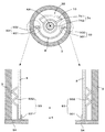
図3は回転支持部の分解組立断面図であり、図4は回転支持部への灯籠本体部および透明ガラス板の取付方法を示す断面図である。なお、図3中の括弧内番号は組立手順の一例を示すものである。 FIG. 3 is an exploded cross-sectional view of the rotation support portion, and FIG. 4 is a cross-sectional view showing a method for attaching the lantern body portion and the transparent glass plate to the rotation support portion. The numbers in parentheses in FIG. 3 show an example of the assembly procedure.
回転支持部5は、大きく分けて軸部材51と、軸部材51の下方端面に取り付けられる羽部材52と、平板中央部に貫通孔531を有する第1平板53と、平板中央部に貫通孔541を有する第2平板54と、複数個(本実施形態では、6個)の金属製またはセラミック製の球体55とを有している。そして、次の手順(1)〜(8)で組み立てられる。以下、装置各部の構成とともに組立手順を説明する。なお、この組立手順は一例であって適宜順序を入れ替えたり、並行して行ってもよいことは言うまでもない。
The
(1)回転支持部5を構成する要素のうち軸部材51は、軸片511の上方端部に対して軸片512が接続されて一体化され、軸方向Xに延びている。このように構成される軸部材51では、軸片511の下方端部および上方端部がそれぞれ本発明の「軸部材の下方端部」および「軸部材の中央部」に相当し、軸片512の上方端部が本発明の「軸部材の上方端部」に相当する。これらの軸片のうち軸片511の上方端部にはフランジ部材が取り付けられている。そして、軸片511の下方端部から第1平板53の貫通孔531を外嵌すると、第1平板53の平板中央部、つまり貫通孔531の周辺部の上面がフランジ部材に係止され、その係止部分を溶接、例えばスポット溶接することで軸片511に対して第1平板53が固定される。また、第1平板53では、平板中央部から水平方向に平板周縁部が延設されており、この平板周縁部の上面は後述するようにして軸部材51に軸支される第2平板44の下面とで球体55を挟み込むことが可能となっている。
(1) Of the elements constituting the
(2)軸片511の下方端面には、軸方向Xにネジ孔が設けられるとともに当該ネジ孔に雌ネジが螺刻されている。そして、水平面内で4方向に羽が放射状に延設された羽部材52が設けられている。この羽部材52の羽中央部には貫通孔が穿設されており、その貫通孔にネジ91を挿通させるとともに、そのネジ91を軸片511のネジ孔に締結することで軸部材51の下方端部に羽部材52が固定される。なお、ネジ91の頭部寸法は削孔21の内径より短く、そのネジ91が締結される羽中央部を中心に4枚の羽が広がった状態では羽部材52の全体寸法は削孔21の内径よりも長くなっている。また、各羽は羽中央部に対して折り曲げ自在となっており、後述するように軸部材51の下方端部を削孔21に圧入すると、その圧入動作に応じて各羽が折り曲げられながら削孔21の内壁面と係合する。
(2) On the lower end face of the
(3)軸片511の上方端面にも、下方端面と同様に、軸方向Xにネジ孔が設けられるとともに当該ネジ孔に雌ネジが螺刻されている。また、その雌ネジに対応する雄ネジが、軸片512の下方端部に螺刻されており、軸片512の下方端部を軸片511の上方端部に螺合して軸片511と一体化することが可能となっている。一方、軸片512の上方端部は下方端部よりも細く、その外径は貫通孔541の内径よりも小さくなっている。このように軸片512の上方端部には、段差部が形成され、第2平板54の貫通孔541を軸片512の上方端部に外嵌すると、第2平板54の下面が第1平板53の上面と平行に対向しながら段差部で係止され、これによって第2平板54を軸支可能となっている。なお、上記のようにして軸片511、512を一体化する際に、軸片512の送り込み量を調整することで軸部材51の軸方向Xの長さを調節し、それによって軸方向Xでの第1平板53と第2平板54との離間間隔を高精度に制御可能となっている。
(3) On the upper end surface of the
(4)第2平板54の平板中央部には上記したように貫通孔541が設けられるのに対し、その平板中央部から水平方向に平板周縁部が延設されるとともに、外周縁に第2平板54全体を取り囲むようにフェンス部543が立設されている。また、この平板周縁部の下面には貫通孔541を中心とする仮想同心円上で6個の凹部542が貫通孔541を取り囲むように等角度間隔で設けられている。なお、図面では凹部の形成により第2平板54の上面の一部が上方に突出した状態が図示されており、これに符号542を付している。この実施形態では、仮想同心円は灯籠本体部3の中空部32の内径よりも小さく、後述するように第2平板54の上面に灯籠本体部3を載置すると、凹部542が中空部32内に入り込んで灯籠本体部3と干渉するのが回避される。
(4) While the through
一方、第2平板54の上面に対し、2つの支持部材93が溶接や接着剤などによって取り付けられる。各支持部材93は、長尺金属片の一方端を断面視で略コ字状となるように折り曲げて透明ガラス板8をすっぽりと嵌入可能に仕上げられたガラス受け部931と、長尺金属片の他方端を三角波状に仕上げてバネ特性を持たせたバネ部932とを有している。2つのガラス受け部931は、図3に示すように開口が鉛直方向の上方に向けられるとともにバネ部932が貫通孔541と反対側に位置する状態で、第2平板54の上面に溶接や接着剤などにより固定されて後述するように上方から降ろされる透明ガラス板8の下方端部を挟み込んで支持可能となっている。
On the other hand, two
(5)第2平板54に形成された凹部542に対して球体55が1個ずつ収容された状態で第2平板54を第1平板53に対向配置して6個の球体55を第1平板53と第2平板54とで挟み込む。この実施形態では作業性を考慮して次のようにして組み立てている。つまり、第2平板54を上下反転させて凹部542を上方に向ける。そして、各凹部542に球体55を1個ずつ収容する。そして、手順(1)〜(3)により形成された構造体(軸部材51+羽部材52+第1平板53)も上下反転させて軸片512の先端部を下方に向け、第2平板54の貫通孔541に遊挿する。こうして、一体化された構造体(軸部材51+羽部材52+第1平板53+第2平板54+球体55+支持部材93)を再度上下反転させて、図3に示す通常姿勢に戻す。この通常姿勢では、第2平板54に対して外力を与えると、球体55が第1平板53の上面上を凹部542内で転動しながら移動し、第2平板54と一体的に軸部材51回りに滑らかに移動する。
(5) In a state where the
(6)軸部材51の上方端面、つまり軸片512の先端面には、軸方向Xにネジ孔が設けられるとともに当該ネジ孔に雌ネジが螺刻されている。そして、ロウソク立て受け部71の底面中央部に設けられた貫通孔(図示省略)にネジ92を挿通させるとともに、そのネジ92を軸片512のネジ孔に締結することで軸部材51の上方端部にロウソク立て受け部71を固定する。また、このネジ締結処理によって第2平板54が軸部材51から抜けるのを防止することができる。なお、このロウソク立て受け部71に対してロウソク立て72を着脱自在となっており、本実施形態では、ロウソク立て受け部71とロウソク立て72とでロウソク支持部7が構成されている。もちろん、ロウソク立て受け部71を設ける代わりに、ロウソク立て72を直接軸部材51の上方端部に固定するように構成してもよい。
(6) A screw hole is provided in the axial direction X on the upper end surface of the
また、本実施形態では、図3に示すように、ロウソク立て受け部71に対して反射板10が取り付けられている。つまり、この反射板10は1枚の金属板を折り曲げて湾曲形成したものであり、ロウソク立て72に立てられたロウソク6を背面側(図1中の下段図における上側)から囲むように配置された状態でロウソク立て受け部71を介して軸部材51に固定される。
In the present embodiment, as shown in FIG. 3, the
(7)このように本実施形態では、灯籠本体部3を支持しながら軸部材51回りに回転させる機構を有する回転支持部5に対し、灯籠本体部3および透明ガラス板8を着脱自在に支持する支持部材93、ロウソク支持部7および反射板10が取り付けられている。そして、軸部材51の下方端部を基台2の上面中央部に形成された削孔21に圧入すると、その圧入動作に応じて羽部材52が上方に折り曲げられながら軸部材51の下方端部が削孔21内に入り込み各羽部材52の先端部が削孔21の内壁面と係合し、回転支持部5が基台2にしっかりと固定される。もちろん、回転支持部5を逆方向、つまり鉛直方向の上方に移動させることで回転支持部5を基台2から取り外すことも可能となっている。このように本実施形態では、回転支持部5は基台2に対して着脱自在となっている。
(7) As described above, in the present embodiment, the
(8)こうして回転支持部5の基台2への装着固定が完了すると、透明ガラス板8を上方側より降ろして透明ガラス板8の下方端部を支持部材93のガラス受け部931に嵌め込み、これによって透明ガラス板8を回転支持部5に取り付ける。その後、さらに灯籠本体部3をバネ部932と係合させながら第2平板54の上面に載置して固定し、最後に灯籠本体部3の上方端部に対して頭部4を嵌入する。この実施形態では、灯籠本体部3に対して頭部4を着脱自在に構成しているが、灯籠本体部3への頭部4の固定を希望する場合には、灯籠本体部3への頭部4の嵌入時に接着剤を用いて頭部4を固定すればよい。
(8) When the mounting and fixing of the
本実施形態では、上記のように構成された支持部材93を利用することで透明ガラス板8および灯籠本体部3を回転支持部5に対して着脱自在としているが、それについて図4を参照しつつ詳しく説明する。第2平板54の上面に固定された支持部材93は、第2平板54の外周縁に立設されたフェンス部543から貫通孔側(図4の左手側)に離れて第2平板54の上面に固定されている。そして、灯籠本体部3が第2平板54に載置されるまで、バネ部932は反貫通孔側(図4の右手側)に少し傾斜しているため、同図(a)に示すように、透明ガラス板8を上方から下降させて透明ガラス板8を支持部材93に設置して固定させる際、透明ガラス板8が多少ふらついたとしてもバネ部932に案内されて透明ガラス板8の下方端部をガラス受け部931に対して確実に挿入可能となっている。
In the present embodiment, the
透明ガラス板8の設置が完了すると、同図(b)に示すように、灯籠本体部3を上方から下降させて透明ガラス板8および支持部材93に外嵌する。この外嵌作業中に、灯籠本体部3の内壁面がバネ部932と係合してバネ部932を透明ガラス板8側に押し遣り透明ガラス板8の外周面とで挟み込む。また、本実施形態では、軸方向Xと直交する水平方向でのバネ部932の幅は透明ガラス板8と灯籠本体部3との間隔よりも広いため、同図(c)に示すように、灯籠本体部3と透明ガラス板8とで挟まれたバネ部932は軸方向Xに強制的に伸張させられて透明ガラス板8と灯籠本体部3とを互いに離間させる方向に付勢して透明ガラス板8に対して灯籠本体部3を固定している。
When the installation of the
また、本実施形態では、フェンス部543で取り囲まれる空間の内径が灯籠本体部3の下方端部の外径とほぼ同一であり、その空間に灯籠本体部3の下方端部を嵌入することで灯籠本体部3の重心が軸部材51の鉛直方向の上方に位置するように設計されているため、灯籠本体部3は回転支持部5に装着固定するのみで灯籠本体部3を正確に位置決めすることができるとともに、フェンス部543で灯籠本体部3の下方端部を保持して灯籠本体部3をしっかりと回転支持部5に固定することができる。もちろん、透明ガラス板8は2つの支持部材93により支持され、灯籠本体部3は2つの支持部材93とフェンス部543とで支持されることで回転支持部5に固定されているため、上記とは逆の手順、つまり灯籠本体部3を上方への持ち上げた後、透明ガラス板8を上方に持ち上げることによって、灯籠本体部3および透明ガラス板8を回転支持部5から取り外すことができる。このように、本実施形態では回転支持部5に対する、透明ガラス板8および灯籠本体部3の着脱が容易であり、優れたメンテナンス性が得られる。
In the present embodiment, the inner diameter of the space surrounded by the
以上のように、本実施形態では、軸部材51の下方端部を基台2に固定した状態で、軸部材51の中央部および上方端部を基台2の上面中央部から上方に突出させている。そして、軸部材51の中央部に対して第1平板53を固定するとともに、6個の球体55を介して第1平板53の上方で第2平板54を軸部材51の上方端部に対して回転自在に軸支している。したがって、第2平板54の上面に灯籠本体部3および透明ガラス板8を固定することで灯籠本体部3および透明ガラス板8を安定して軸部材51から鉛直方向に延びる回転軸を中心に回転させることができる。このように、上記のように構成された回転支持部5を用いることで、中空石材で形成された灯籠本体部3であっても安定して回転させることができる。したがって、開口部33が正面を向くように灯籠本体部3を回転して位置決めすると、開口部33から灯籠本体部3の中空内部にアクセスしてロウソク立て受け部71に対するロウソク立て72の着脱を行ったり、灯籠本体部3の中空内部に配置されたロウソク6への点火などを行うことができる。また、ロウソク6への点火後に、格子模様部を有する開口部31が正面を向くように灯籠本体部3を回転して位置決めすると、開口部31を介してロウソク6の灯火が導き出される。このように回転支持部5を用いることで灯籠本体部3を回転させてロウソク6の点火作業を円滑に行うことができる。
As described above, in the present embodiment, with the lower end portion of the
また、上記実施形態では、第1平板53および第2平板54の間で球体55が転がることで灯籠本体部3および透明ガラス板8を回転させており、基台2と灯籠本体部3とが衝突したり、擦れ合うことがないだけでなく、基台2および灯籠本体部3のいずれも回転支持部5と擦れ合うことはなく、基台2や灯籠本体部3から粉塵が発生するのを防止することができる。
Moreover, in the said embodiment, the
また、上記実施形態では、ロウソク支持部7に支持されるロウソク6の背面に反射板10が配置されてロウソク6からの光を正面に反射させているが、この反射板10は、反射機能のみならず、通常使用時(格子模様付の開口部31が正面を向いてロウソク6の灯火を正面側に取り出している時)、図1(a)に示すように背面側に位置する開口部33を塞いでロウソク6が消え難くする機能を発揮する。
Moreover, in the said embodiment, although the reflecting
また、上記実施形態では、開口部31に格子模様部を設けることで視認性が確保しつつユーザが当該開口部31を介してロウソク6の火に触れるのを防止することができる。しかも、この開口部31に塞ぐように透明ガラス板8を設けているため、視認性を確保しつつ格子模様付の開口部31から風が入り込んでロウソク6の火が消えるのを防止することができる。
Moreover, in the said embodiment, it can prevent that a user touches the fire of the
さらに、上記実施形態では、第1平板53は単純平板形状であるため、ロウソク6のロウが溶けて軸部材51を伝わって落ちてきたとしても、回転支持部5の周辺外部に案内して排出する。したがって、回転支持部5の内部にロウが滞留して回転性能を劣化させるのを効果的に防止することができる。また、石製灯籠1を使用している間に、第1平板53と第2平板54との間に砂や塵などの粉塵が入り込むことがあるが、上記のように単純平板形状の第1平板53を用いているため、粉塵を取り除きやすく、メンテナンス性に優れている。
Furthermore, in the above embodiment, since the first
このように本実施形態では、灯籠本体部3が本発明の「被回転体」に相当し、開口部31に形成された格子模様部が本発明の「格子状部」に相当し、透明ガラス板8が本発明の「透明部材」に相当する。
Thus, in this embodiment, the lantern
なお、本発明は上記した実施形態に限定されるものではなく、その趣旨を逸脱しない限りにおいて上述したもの以外に種々の変更を行うことが可能である。例えば図5に示すように第2平板54を単純平板形状に仕上げてもよい。なお、図5では、装置各部の配置関係を明示することを優先し、装置各部の寸法関係の一部は実製品から外れている。
The present invention is not limited to the above-described embodiment, and various modifications other than those described above can be made without departing from the spirit of the present invention. For example, as shown in FIG. 5, the second
図5に示す実施形態では、第2平板54は単純平板形状となっている、つまりフェンス部543が設けられていない。また、同図に示すように、軸部材51から鉛直方向の上方に延びる回転中心軸AXに対して支持部材93がほぼ対称に配置されている。したがって、バネ部932で発生する付勢力は回転中心軸AXから互いに反対方向に作用し、ガラス板8に対して灯籠本体部3を互いに180゜ずれた方向に押圧しながら支持している。このため、灯籠本体部3は単に第2平板54の上面に載置されているだけでなく、支持部材93のガラス受け部931で固定されたガラス板8を介してバネ部932の付勢力で回転支持部5に固定されている。
In the embodiment shown in FIG. 5, the second
また、上記実施形態では、基台や地盤などの基礎に軸部材51を固定し、その軸部材51に対して第1平板53を固定しているが、例えば図6に示すように、第1平板53を基台などの基礎に固定するとともに当該第1平板53に軸部材53を固定してもよい。以下、図6を参照しつつ本発明の第3実施形態について説明する。
Moreover, in the said embodiment, although the
図6は本発明にかかる回転支持装置の第3実施形態を装備した石製灯籠を示す図である。第3実施形態が第1実施形態と大きく相違する点は、上記したように基台2への固定方式であり、その他の構成は基本的に同一であるため、相違点を中心に詳述し、同一構成に対しては同一符号を付して構成説明を省略する。
FIG. 6 is a view showing a stone lantern equipped with a third embodiment of the rotation support device according to the present invention. The third embodiment is greatly different from the first embodiment in the manner of fixing to the
第3実施形態では、軸部材51は、第1実施形態で採用した軸片512と、リング形状の軸片513とで構成されている。これらのうち軸片513の貫通孔には、軸片512の雄ネジと螺合可能な雌ネジが刻設されており、軸片513に軸片512の下方端部を螺合することで軸片513と一体化し、軸部材51を構成することが可能となっている。このように構成される軸部材51の第1平板53への固定手順の一例では、同図中の符号(3′)で示すように、軸片513を第1平板53の上面中央部に溶接や接着剤などにより固定した後、その軸片513の貫通孔に軸片512の下方端部を螺入する。こうすることで、第1平板53の上面中央部から軸部材51が上方に立設された状態となる。
In the third embodiment, the
そして、第1実施形態の手順(4)〜(6)と同様の手順によって回転支持部5を組み立てることができ、組み立てられた回転支持部5は、第1実施形態と同様に、灯籠本体部3を支持しながら軸部材51回りに回転させる機構を有する。それに続いて、回転支持部5に対し、灯籠本体部3および透明ガラス板8を着脱自在に支持する支持部材93、ロウソク支持部7および反射板10が取り付けられた後、第1平板53の下面が接着剤や両面テープなどにより基台2の上面(水平面)22に固定される(符号(7′)参照)。
And the
こうして回転支持部5の基台2への装着固定が完了すると、第1実施形態と同様に、透明ガラス板8の取付、第2平板54の上面への灯籠本体部3の固定、および灯籠本体部3への頭部4の嵌入を行って石製灯籠1を完成させる。
When the mounting and fixing of the
以上のように、第3実施形態においても、回転支持部5の基台2への装着固定方法が異なるものの、灯籠本体部3を回転させる機構は第1実施形態と全く同一であり、第1実施形態と同様の作用効果が得られる。しかも、図3(第1実施形態)と図6(第3実施形態)との対比からも明らかなように、第3実施形態では、基台2に削孔21を設ける工程(1)が不要であり、また羽部材52を設ける工程(2)が不要であり、第1実施形態に比べて回転支持部5の構成を簡素化することができるとともに、作業効率を向上させることができる。
As described above, the mechanism for rotating the
また、上記実施形態では、第1平板53を単純平板形状に仕上げているが、外周縁にフェンス部を立設してもよいことは言うまでもない。
Moreover, in the said embodiment, although the 1st
また、上記実施形態では、第2平板54に6個の凹部542を設けるとともに、各凹部542に球体55を1つずつ収容しているが、凹部542に収容すべき球体55の個数は特に限定されるものではなく、例えば複数個ずつ収容してもよい。また、凹部542の個数を球体55の個数と一致させることは本発明の必須構成要件ではなく、例えば1つの円環状の凹部に対して3個以上の球体55を収容するように構成してもよい。なお、第1平板53に対し、第2平板54を水平に回転自在に支持するためには球体55を3個以上設ければよいが、安定的な回転動作を得るためには、球体55の個数はある程度、例えば上記実施形態のように6個程度設けるのが望ましい。
In the above-described embodiment, six
また、上記実施形態では、球体55を転動自在に収容するための凹部を第2平板54に設けているが、第1平板53の上面に凹部を設けてもよい。つまり、第1平板および第2平板のうちの一方の平板に対し、他方の平板と対向する面に凹部を形成し、当該凹部内で球体を転動自在に収容するように構成すればよい。
Further, in the above-described embodiment, the recess for accommodating the
また、上記実施形態では、2つの軸片511、512(または512、513)をつなぎ合わせて軸部材51を構成しているが、単一の軸片により軸部材51を構成してもよく、軸構造や第1平板53との固定態様(ネジなどによる機械的な接続、溶接、接着剤など)も任意である。また、軸片512を複数部材で構成してもよい。例えば、雄ネジ部材の上面にワッシャーなどのリング部材を取り付けたものと軸片512として使用してもよく、この場合、貫通孔541の内径に応じたリング部材を用いることができる。また、リング部材の厚みを変更することで平板54とロウソク立て受け部71とのクリアランスを調節することができる。
Moreover, in the said embodiment, although the
また、上記実施形態では、平板54とロウソク立て受け部71との間にクリアランスを設けることで、ロウソク立て受け部71および反射板10を固定したまま、第2平板54および灯籠本体部3を一体的に回転させるように構成しているが、平板54とロウソク立て受け部71との間にフェルト製や樹脂製のリング状部材を介挿させてクリアランスを解消した状態で回転させるように構成してもよい。
Moreover, in the said embodiment, by providing a clearance between the
また、上記実施形態では、灯籠本体部3と頭部4とを個別に製作し、両者を組み合わせているが、灯籠本体部3と頭部4とを予め一体的に製作してもよい。また、灯籠本体部3単体を回転支持部で回転自在に支持して石製灯籠を構成してもよい。ただし、この場合、灯籠本体部3の内部に雨粒や風などが侵入するのを防止するために、灯籠本体部3については、天井面が設けられた中空形状に仕上げるのが望ましい。
Moreover, in the said embodiment, although the lantern main-
また、上記実施形態では、灯籠本体部3を第2平板54に固定するために支持部材93を用いているが、灯籠本体部3の第2平板54への固定方法はこれに限定されるものではなく、任意の固定方法を用いることができる。例えば接着剤により固定してもよい。この点に関しては、透明ガラス板8の固定についても同様であり、例えば第2平板54に対して接着剤により透明ガラス板8を取り付けてもよい。あるいは、第2平板54に固定された灯籠本体部3に透明ガラス板8を接着剤で固定してもよい。
Moreover, in the said embodiment, although the
また、上記実施形態では、通常使用時に視認性を確保しつつユーザが開口部31を介してロウソク6の火に触れるのを防止するために、開口部31に格子模様部を形成するとともに、透明ガラス板8を設けているが、いずれか一方のみを採用してもよい。ただし、開口部31から風が入り込んでロウソク6の火が消えるのを防止するという観点からすれば、少なくとも透明ガラス板8を設けるのが望ましい。
Moreover, in the said embodiment, in order to prevent a user touching the fire of the
また、上記実施形態では、中空石材で形成された灯籠本体部3を本発明の「被回転体」として回転支持部5によって基台2に対して回転させているが、灯籠本体部3以外の中空石材や石柱を本発明の「被回転体」として回転支持部5によって基台2に対して回転させるように構成してもよい。例えば円柱形状の墓誌を「被回転体」として第2平板54の上面に接着剤や固定金具などを用いて固定し、回転支持部5により墓誌を回転させることができる。このように墓誌などの被回転体に対して加工を加えることなく、しかも被回転体が石柱である場合はもちろんのこと中空石材であったとしても、被回転体を第2平板54の上面で支持した状態のまま軸部材51回りで滑らかに回転させることができる。また、被回転体の重心が軸部材51の鉛直方向の上方に位置しない場合には被回転体の回転が不安定となるが、この場合、被回転体の重心が軸部材51の鉛直方向の上方に位置するように第2平板54上での被回転体の位置を調整することで容易に回転の安定化を図ることができる。さらに、第1平板53および第2平板54の間で球体55を転動させることで被回転体を回転させているため、図1に示す実施形態と同様に、基台2と被回転体とが衝突したり、擦れ合うことがないだけでなく、基台2および被回転体のいずれも回転支持部5と擦れ合うことはなく、基台2や被回転体から粉塵が発生するのを防止することができる。
Moreover, in the said embodiment, although the lantern main-
また、上記実施形態では、石製灯籠1に用いる専用の基台2の上面中央部に削孔21を形成して回転支持部5を固定したり、第1平板53の下面を基台2の上面22に固定しているが、例えば石碑の一部に対して回転支持部5を固定してもよく、このように石碑などを本発明の「基台」として使用して石製灯籠を構築してもよい。また、基台以外に、地面や岩盤などの地盤に対して削孔を形成し、地盤に直接的に回転支持部5を固定してもよい。また、このように基台2や地盤などの基礎に回転支持部5の軸部材51の下方端部を固定する方法は上記実施形態に記載された方式に限定されるものではなく、任意の固定方法を採用することができる。例えば接着剤やコンクリートなどを用いて軸部材の下方端部や第1平板を基台や地盤などの基礎に固定してもよい。
Moreover, in the said embodiment, the
この発明は、基台や地盤などの基礎に対し、石柱または中空石材で形成される被回転体を回転自在に支持する回転支持装置および該回転支持装置を装備する石製灯籠全般に適用することができる。 The present invention is applied to a rotation support device that rotatably supports a rotating body formed of a stone pillar or a hollow stone material with respect to a foundation such as a base or a ground, and to stone lanterns generally equipped with the rotation support device. Can do.
1…石製灯籠
2…基台(基礎)
3…灯籠本体部(中空石材)
5…回転支持部(回転支持装置)
6…ロウソク
7…ロウソク支持部
8…透明ガラス板(透明部材)
10…反射板
22…基台の上面(水平面)
31…(第1)開口部
32…中空部
33…(第2)開口部
51…軸部材
55…球体
71…ロウソク立て受け部
72…ロウソク立て
511、512、513…軸片
542…凹部
X…軸方向
1 ...
3. Lantern body (hollow stone)
5 ... Rotation support part (Rotation support device)
6 ...
10 ...
DESCRIPTION OF
Claims (7)
下方端部が前記基礎に固定されて中央部および上方端部が前記基礎から上方に突出する軸部材と、
平板中央部が前記軸部材の中央部に固定されるとともに平板周縁部が前記平板中央部から水平方向に延びる第1平板と、
前記被回転体を支持する上面を有し、下面を前記第1平板の上面と平行に対向した状態で前記軸部材の上方端部に対して回転自在に軸支される第2平板と、
前記第1平板と前記第2平板で挟まれる3個以上の球体とを備え、
前記第1平板および前記第2平板のうちの一方の平板では、他方の平板と対向する面に凹部が形成され、前記球体を転動自在に収容することを特徴とする回転支持装置。 A rotation support device that rotatably supports a rotating body formed of a stone pillar or a hollow stone material with respect to a foundation such as a base or a ground,
A shaft member whose lower end is fixed to the foundation and whose center and upper end protrude upward from the foundation;
A first flat plate having a flat plate central portion fixed to the central portion of the shaft member and a flat plate peripheral portion extending in a horizontal direction from the flat plate central portion;
A second flat plate rotatably supported with respect to the upper end portion of the shaft member with an upper surface supporting the rotated body and a lower surface facing the upper surface of the first flat plate in parallel.
Comprising three or more spheres sandwiched between the first flat plate and the second flat plate;
In one of the first flat plate and the second flat plate, a concave portion is formed on a surface facing the other flat plate, and the sphere is rotatably accommodated.
下面が前記基礎の上面に固定される第1平板と、
下方端部が前記第1平板の上面中央部に固定されるとともに、上方端部が上方に延びる軸部材と、
前記被回転体を支持する上面を有し、下面を前記第1平板の上面と平行に対向した状態で前記軸部材の上方端部に対して回転自在に軸支される第2平板と、
前記第1平板と前記第2平板で挟まれる3個以上の球体とを備え、
前記第1平板および前記第2平板のうちの一方の平板では、他方の平板と対向する面に凹部が形成され、前記球体を転動自在に収容することを特徴とする回転支持装置。 A rotation support device that rotatably supports a rotating body formed of a stone pillar or a hollow stone material with respect to a foundation such as a base or a ground,
A first flat plate whose lower surface is fixed to the upper surface of the foundation;
A shaft member whose lower end is fixed to the center of the upper surface of the first flat plate and whose upper end extends upward;
A second flat plate rotatably supported with respect to the upper end portion of the shaft member with an upper surface supporting the rotated body and a lower surface facing the upper surface of the first flat plate in parallel.
Comprising three or more spheres sandwiched between the first flat plate and the second flat plate;
In one of the first flat plate and the second flat plate, a concave portion is formed on a surface facing the other flat plate, and the sphere is rotatably accommodated.
前面に第1開口部が設けられるとともに後面に第2開口部が設けられる中空石材と、
請求項1ないし4のいずれか一項に記載の回転支持装置と同一の構成を有し、前記石製基台に対し、前記中空石材を回転自在に支持する回転支持部と、
前記中空石材の内部でロウソクを支持するロウソク支持部とを備え、
前記回転支持部は、前記第2平板の上面で前記中空石材を支持し、
前記ロウソク支持部は前記軸部材の上方端部に設けられることを特徴とする石製灯籠。 A stone base,
A hollow stone material provided with a first opening on the front surface and a second opening on the rear surface;
A rotation support unit having the same configuration as the rotation support device according to any one of claims 1 to 4, and rotatably supporting the hollow stone material with respect to the stone base,
A candle support part for supporting a candle inside the hollow stone material,
The rotation support portion supports the hollow stone material on the upper surface of the second flat plate,
The candle lantern is provided at an upper end of the shaft member.
前記第1開口部には、前記第1開口部を部分的に覆う格子状部が設けられ、
前記中空石材を回転させて前記第1開口部を正面に位置決めした際、前記反射板が前記第2開口部を塞ぐように前記反射板の下端部が前記軸部材の上方端部または前記ロウソク支持部に固定される請求項5に記載の石製灯籠。 Further comprising a reflector arranged on the back of the candle supported by the candle support part and reflecting light from the candle to the front;
The first opening is provided with a lattice portion that partially covers the first opening,
When the hollow stone is rotated and the first opening is positioned in front, the lower end of the reflecting plate is supported by the upper end of the shaft member or the candle so that the reflecting plate closes the second opening. The stone lantern according to claim 5, which is fixed to the portion.
Priority Applications (1)
| Application Number | Priority Date | Filing Date | Title |
|---|---|---|---|
| JP2011032750A JP5721468B2 (en) | 2011-02-18 | 2011-02-18 | Stone lantern |
Applications Claiming Priority (1)
| Application Number | Priority Date | Filing Date | Title |
|---|---|---|---|
| JP2011032750A JP5721468B2 (en) | 2011-02-18 | 2011-02-18 | Stone lantern |
Publications (2)
| Publication Number | Publication Date |
|---|---|
| JP2012174377A true JP2012174377A (en) | 2012-09-10 |
| JP5721468B2 JP5721468B2 (en) | 2015-05-20 |
Family
ID=46977137
Family Applications (1)
| Application Number | Title | Priority Date | Filing Date |
|---|---|---|---|
| JP2011032750A Active JP5721468B2 (en) | 2011-02-18 | 2011-02-18 | Stone lantern |
Country Status (1)
| Country | Link |
|---|---|
| JP (1) | JP5721468B2 (en) |
Cited By (1)
| Publication number | Priority date | Publication date | Assignee | Title |
|---|---|---|---|---|
| CN103851071A (en) * | 2012-11-30 | 2014-06-11 | 深圳市海洋王照明工程有限公司 | Rotating shaft device and lamp holder rotating adjusting device |
Citations (4)
| Publication number | Priority date | Publication date | Assignee | Title |
|---|---|---|---|---|
| JPS60123427U (en) * | 1984-01-30 | 1985-08-20 | 株式会社東芝 | Reel stand device |
| JPS6358401U (en) * | 1986-10-02 | 1988-04-19 | ||
| JPH0874445A (en) * | 1994-07-01 | 1996-03-19 | Sougenshiya:Kk | Cinerary tower |
| JPH10275520A (en) * | 1997-03-31 | 1998-10-13 | Kurosaki Kinzoku Kogei Seisakusho:Kk | Candlestick for grave |
-
2011
- 2011-02-18 JP JP2011032750A patent/JP5721468B2/en active Active
Patent Citations (4)
| Publication number | Priority date | Publication date | Assignee | Title |
|---|---|---|---|---|
| JPS60123427U (en) * | 1984-01-30 | 1985-08-20 | 株式会社東芝 | Reel stand device |
| JPS6358401U (en) * | 1986-10-02 | 1988-04-19 | ||
| JPH0874445A (en) * | 1994-07-01 | 1996-03-19 | Sougenshiya:Kk | Cinerary tower |
| JPH10275520A (en) * | 1997-03-31 | 1998-10-13 | Kurosaki Kinzoku Kogei Seisakusho:Kk | Candlestick for grave |
Cited By (1)
| Publication number | Priority date | Publication date | Assignee | Title |
|---|---|---|---|---|
| CN103851071A (en) * | 2012-11-30 | 2014-06-11 | 深圳市海洋王照明工程有限公司 | Rotating shaft device and lamp holder rotating adjusting device |
Also Published As
| Publication number | Publication date |
|---|---|
| JP5721468B2 (en) | 2015-05-20 |
Similar Documents
| Publication | Publication Date | Title |
|---|---|---|
| CN101360949B (en) | Self-righting light fixture | |
| US8113672B2 (en) | Outer mirror | |
| JP2007504459A5 (en) | ||
| JPWO2014156292A1 (en) | Microphone support device for sound source exploration | |
| JP5721468B2 (en) | Stone lantern | |
| CN206036708U (en) | Lighting appliance | |
| CN103175115B (en) | Light fixture swinging mounting and the Gao Dingdeng containing this light fixture swinging mounting | |
| JP2008140593A (en) | Embedded type illumination fixture | |
| US10422510B2 (en) | Light fixture with pivotable optic | |
| JP2007009418A (en) | Balustrade | |
| JP2010218919A (en) | Arm for spotlight, spotlight, and ceiling-embedded type spotlight unit | |
| TW201740024A (en) | Ceiling fan structure having at least one blade which is expanded when being in rotation and collapsed when being not in rotation | |
| CN101153505B (en) | Universal connector | |
| JP4280997B2 (en) | Recessed ceiling lighting fixture | |
| JP2018071200A (en) | Light source unit and construction lamp | |
| CA2704302C (en) | Fan device having simultaneously foldable blades | |
| JP5402448B2 (en) | Dome camera | |
| KR101816749B1 (en) | Hub connector for dome-shaped house | |
| TWI609524B (en) | Holder and antenna fixed device having same | |
| JP2020200804A (en) | Blade device | |
| JP6475291B2 (en) | Lighting device | |
| US20230213158A1 (en) | Natural lighting device | |
| CN210426562U (en) | Laser line marking instrument turntable with split type stamping structure | |
| CN219588848U (en) | Ceiling lamp mounting structure | |
| JP3138951U (en) | Candle stand that also serves as a mirror ball |
Legal Events
| Date | Code | Title | Description |
|---|---|---|---|
| A621 | Written request for application examination |
Free format text: JAPANESE INTERMEDIATE CODE: A621 Effective date: 20140131 |
|
| A977 | Report on retrieval |
Free format text: JAPANESE INTERMEDIATE CODE: A971007 Effective date: 20141029 |
|
| A131 | Notification of reasons for refusal |
Free format text: JAPANESE INTERMEDIATE CODE: A131 Effective date: 20141104 |
|
| A521 | Written amendment |
Free format text: JAPANESE INTERMEDIATE CODE: A523 Effective date: 20150105 |
|
| TRDD | Decision of grant or rejection written | ||
| A01 | Written decision to grant a patent or to grant a registration (utility model) |
Free format text: JAPANESE INTERMEDIATE CODE: A01 Effective date: 20150303 |
|
| A61 | First payment of annual fees (during grant procedure) |
Free format text: JAPANESE INTERMEDIATE CODE: A61 Effective date: 20150324 |
|
| R150 | Certificate of patent or registration of utility model |
Ref document number: 5721468 Country of ref document: JP Free format text: JAPANESE INTERMEDIATE CODE: R150 |
|
| R250 | Receipt of annual fees |
Free format text: JAPANESE INTERMEDIATE CODE: R250 |