JP2012173095A - Road surface flatness measuring device - Google Patents
Road surface flatness measuring device Download PDFInfo
- Publication number
- JP2012173095A JP2012173095A JP2011034583A JP2011034583A JP2012173095A JP 2012173095 A JP2012173095 A JP 2012173095A JP 2011034583 A JP2011034583 A JP 2011034583A JP 2011034583 A JP2011034583 A JP 2011034583A JP 2012173095 A JP2012173095 A JP 2012173095A
- Authority
- JP
- Japan
- Prior art keywords
- road surface
- vehicle
- measuring device
- distance
- surface flatness
- Prior art date
- Legal status (The legal status is an assumption and is not a legal conclusion. Google has not performed a legal analysis and makes no representation as to the accuracy of the status listed.)
- Pending
Links
Images


Abstract
Description
本発明は、高速道路や普通道路等の路面の形状を、自動車の通常の走行速度で測定できるようにした路面平坦性測定装置に関するものである。 The present invention relates to a road surface flatness measuring apparatus capable of measuring the shape of a road surface such as an expressway or an ordinary road at a normal traveling speed of an automobile.
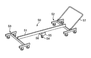
従来の路面平坦性測定装置として代表的なものに、実用新案登録第3139705号公報のものがある。この路面平坦性測定装置50は、図5の如く、支持フレーム51の前側及び後側に、それぞれ4つのキャスターにて接地した前部台車52と後部台車53とを有し、前記支持フレーム51の中央部に上下動可能に測定車輪54を設けてなり、前記前部台車52と後部台車53との接地レベルに対する測定車輪54の上下の変位を算定する変位測定エンコーダ55と、測定車輪54の移動距離を測定する距離測定エンコーダ56とを設けている。しかして、前部台車52側に牽引用のハンドル57を備えている。
A typical example of a conventional road surface flatness measuring apparatus is that of Utility Model Registration No. 3139705. As shown in FIG. 5, the road surface
したがって、作業者が、前記ハンドル57にて前記路面平坦性測定装置50を牽引しつつ路面上を走行させると、前記測定車輪54が距離測定エンコーダ56により計測しつつ進み、設定した距離ごとに、前部台車52と後部台車53の接地レベルに対する測定車輪54の上下変位が変位測定エンコーダ55により測定され、その測定データがパソコン等のデータ処理ユニットに伝送され、リアルタイムに記録されるようになっていた。
しかしながら、上記従来の路面平坦性測定装置50では、前記測定車輪54からの情報により変位測定エンコーダ55及び距離測定エンコーダ56が作動し、これらからの測定データの伝送を受領するパソコン等のデータ処理ユニットを支持フレームに積載することは困難であり、したがって、ケーブル或いは無線を使ってパソコン等のデータ処理ユニットに伝送するため、測定できる範囲が限られていたし、作業者の人力に頼ることが多く、路面上を走行させる距離にも限界があった。また、測定に多くの時間と労力を要することとなっていた。
However, in the conventional road surface
本発明は、上記の問題を解消したもので、その目的とするところは、高速道路や普通の道路等の路面を走る自動車に、通常の走行速度で走行させつつ路面の平坦性が測定できるようにした路面平坦性測定装置を提供することにある。 The present invention solves the above-described problems, and the object of the present invention is to allow a vehicle running on a road surface such as a highway or a normal road to measure the flatness of the road surface while traveling at a normal traveling speed. An object of the present invention is to provide a road surface flatness measuring apparatus.
上記目的を達成するため、本発明の路面平坦性測定装置は、自動車の走行方向に沿った3個所に、それぞれ路面までの高さを測定するレーザ測距器を備え、該レーザ測距器のうち、前後2つの測距値を結んだ基準線に対する中間の1つの測距値の変動により路面の形状を測定することを特徴とし、自動車を通常の走行速度で走らせながら路面の平坦性が測定できるように構成した。 In order to achieve the above object, a road surface flatness measuring apparatus according to the present invention includes laser distance measuring devices for measuring the height to the road surface at three locations along the direction of travel of the automobile, and the laser distance measuring device of the laser distance measuring device. Among them, it is characterized by measuring the shape of the road surface by the variation of one distance value in the middle with respect to the reference line connecting the two distance measurement values before and after, and measuring the flatness of the road surface while running the car at normal driving speed Configured to be possible.
また、請求項2に記載の路面平坦性測定装置は、前記レーザ測距器が、トラックの荷台下の空間に等間隔に設置されていることを特徴とし、荷台がパソコン等のデータ処理ユニット及びその付属機器の積載スペースとして利用できるように構成した。 The road surface flatness measuring apparatus according to claim 2 is characterized in that the laser rangefinders are installed at equal intervals in a space under a truck bed, and the bed is a data processing unit such as a personal computer and the like. It was configured to be used as a loading space for the attached equipment.
さらに、請求項3に記載の路面平坦性測定装置は、前記自動車の車輪が、距離測定エンコーダになっていることを特徴とし、路面の平坦性の測定において、測定距離が大径の車輪により得られるように構成した。
Furthermore, the road surface flatness measuring apparatus according to
本発明によれば、自動車を通常の走行速度で走らせながら路面の平坦性を測定でき、しかも、車上や車内にパソコン等のデータ処理ユニット及びその付属機器を搭載でき、測定する路面上の距離に限界がなく、測定が短時間で済み、時間と労力が大いに節約できる等の各種の優れた効果を奏するものである。 According to the present invention, it is possible to measure the flatness of the road surface while driving the vehicle at a normal traveling speed, and it is possible to mount a data processing unit such as a personal computer or the like on the vehicle or in the vehicle, and to measure the distance on the road surface. There are various advantages such as that there is no limit, the measurement can be completed in a short time, and time and labor can be greatly saved.
また、請求項2の発明によれば、各レーザ発受振器がトラックの荷台下に等間隔に設置され、荷台がパソコン等のデータ処理ユニット及びその付属機器の積載が可能となり、測定範囲を大幅に拡大できるという優れた効果を奏するものである。 Further, according to the invention of claim 2, the laser transducers are installed at equal intervals under the truck bed, and the bed can be loaded with a data processing unit such as a personal computer and its associated equipment, greatly increasing the measurement range. It has an excellent effect that it can be expanded.
また、請求項3の発明によれば、路面の平坦性の測定において、測定距離が大径の車輪により得られることから、測定距離が、30m、50mという短くも、逆に、10Km、20Kmと長くなっても常に、正確な距離測定及び平坦性の測定ができるという優れた効果を奏するものである。
According to the invention of
次に、本発明の実施の態様を添付図面に基づいて説明する。図1は本願装置をトラックに取付けた状態を示す側面図、図2はレーザ測距器の取付枠による取付け状態を示す斜視図、図3は本願装置の概要を示すブロック図、図4は本願装置による測定したデータの概略図、図5は従来装置を示す斜視図である。 Next, embodiments of the present invention will be described with reference to the accompanying drawings. 1 is a side view showing a state in which the device of the present invention is attached to a track, FIG. 2 is a perspective view showing a state of attachment of the laser rangefinder by an attachment frame, FIG. 3 is a block diagram showing an outline of the device of the present application, and FIG. FIG. 5 is a perspective view showing a conventional apparatus.
図1において、1は路面平坦性測定装置を搭載した自動車であって、該自動車1として図示の場合はトラックが示されているが、乗用車でも、ワンボックスカーでも、特注の専用車両その他でもよい。前記トラック1は、運転席1a、荷台1b及びその側壁1b′、車輪(前輪及び後輪)1cを備える。該トラック1の場合、その荷台下の空間の、走行方向に沿った3個所に、レーザ測距器2a、2b、2cを設置している。なお、トラックに比して車体下の空間の小さい乗用車やワンボックスカーでは、レーザ測距器と路面との距離を確保するために、必要に応じて床部に穴を開けることもある。
In FIG. 1, reference numeral 1 denotes an automobile on which a road surface flatness measuring device is mounted. In the case of the automobile 1, a truck is shown, but it may be a passenger car, a one-box car, a custom-made exclusive vehicle, or the like. . The truck 1 includes a driver's
前記レーザ測距器2a、2b、2cは、図2の如く、前記トラック1の荷台の側壁1b′の上端縁に、フックを介して引っ掛けて取付けた取付枠4に固定した枝枠4aの端部に路面3に向けて同高位置に取付けられている。
As shown in FIG. 2, the
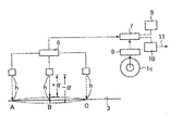
前記レーザ測距器2a、2b、2cによる路面3までの測距は、図示していないが、レーザ照射部と、レーザ受光部を隣接配置してなり、図3の如く、それぞれ路面3までの高さhが測定できるようになっている。この測定はトラック1の走行中に測定できる。ここに使われるレーザは、He−Neレーザを含み、昼間の明るい光の中でも測距できるものである。尤も、太陽光によって誤動作が生ずる虞があるときはレーザ測距器にカバーを付けて日陰を作るように対処することがよい。
Although the distance measurement to the
前記レーザ測距器2a、2b、2cは、トラック1の荷台1b上に搭載したパソコン等のデータ処理ユニット及びその付属機器(図示せず)に、それぞれケーブル5を介して荷台1bの側壁1b′を超えて連繋している。勿論、荷台の床を貫通させてもよい。
The
前記自動車1の走行方向に沿った3個所に設置されたレーザ測距器2a、2b、2cのうち、前後2つのレーザ測距器2a、2cの測距ポイントA、Cにおける測距値を結んだ基準線(図3では路面3に相当)に対する中間のレーザ測距器2bによる測距ポイントBの測距値の変動により路面3の形状が測定できるようになっている。
Of the laser distance measuring
換言すれば、前後2つのレーザ測距器2a、2cの測距ポイントA、Cにおける測距値は路面3のレベルを示し、中間のレーザ測距器2bによる測距ポイントBが沈んでいるときは、測距値はマイナスαとなり、中間のレーザ測距器2bによる測距ポイントBが盛り上がっているときは、測距値はプラスαとなる。
In other words, the distance measurement values at the distance measurement points A and C of the two front and rear laser
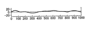
しかして、前記3つのレーザ測距器2a、2b、2cにより得られた測距値は、比較器6により比較されてパソコン7に伝送され、車輪1cの回転数から得た距離測定エンコーダ8の情報を加味して演算されて記憶される。この伝送されたデータは、リアルタイムでモニタ9に画像として出力できるとともに、記憶されたデータは、プリンタ10により適時、データシート或いはグラフ等の出力物11として印字出力される。図4は10mごとの路面3の形状を測定し、1Kmにわたって測定したものである。なお、この図においては、細かい数値は省略し、全体の形状のみが判るように示している。
Thus, the distance values obtained by the three laser
前記路面平坦性測定装置を搭載した自動車により長距離を測定するとき、距離が伸びる程に、位置情報に誤差が生ずる可能性は否定できない。この誤差を修正する手段として2つある。一つは、GPSの位置情報を取り込むこと、二つは前記自動車にレーザセンサーを搭載し、路肩の定点に反射板を設置することで距離信号に目印を付けることであり、この2つは本願装置にオプションとして設置し得るし、他に誤差を修正する手段があればそれによることもある。 When a long distance is measured by an automobile equipped with the road surface flatness measuring device, the possibility that an error occurs in position information as the distance increases cannot be denied. There are two means for correcting this error. One is to capture GPS position information, and the other is to mount a laser sensor on the car and place a reflector at a fixed point on the shoulder to mark the distance signal. It can be installed as an option on the device, and possibly other means to correct the error.
本願の路面平坦性測定装置は、道路上を走る自動車に、通常の走行速度で走行させつつ路面の平坦性を測定できるようにしたもので、高速道路のような長い距離の路面の平坦性を測定することも、また、アンダーパスを通して立体交差にする工事区間に限って短い距離の路面の平坦性を測定することも、短時間にして小労力にて測定可能であり、産業上広く利用することができるものである。 The road surface flatness measuring device of the present application enables a vehicle running on a road to measure the flatness of a road surface while traveling at a normal traveling speed. It is also possible to measure the flatness of the road surface over a short distance only in the construction section where the three-dimensional intersection is made through an underpass. It is something that can be done.
1 自動車(トラック)
1a 運転席
1b 荷台
1b′側壁
1c 車輪
2a、2b、2c レーザ測距器
3 路面
4 取付枠
4a 枝枠
5 ケーブル
6 比較器
7 パソコン
8 距離測定エンコーダ
9 モニタ
10 プリンタ
11 出力物
A、B、C 測距ポイント
1 Car (truck)
DESCRIPTION OF
Claims (3)
Priority Applications (1)
| Application Number | Priority Date | Filing Date | Title |
|---|---|---|---|
| JP2011034583A JP2012173095A (en) | 2011-02-21 | 2011-02-21 | Road surface flatness measuring device |
Applications Claiming Priority (1)
| Application Number | Priority Date | Filing Date | Title |
|---|---|---|---|
| JP2011034583A JP2012173095A (en) | 2011-02-21 | 2011-02-21 | Road surface flatness measuring device |
Publications (1)
| Publication Number | Publication Date |
|---|---|
| JP2012173095A true JP2012173095A (en) | 2012-09-10 |
Family
ID=46976140
Family Applications (1)
| Application Number | Title | Priority Date | Filing Date |
|---|---|---|---|
| JP2011034583A Pending JP2012173095A (en) | 2011-02-21 | 2011-02-21 | Road surface flatness measuring device |
Country Status (1)
| Country | Link |
|---|---|
| JP (1) | JP2012173095A (en) |
Cited By (7)
| Publication number | Priority date | Publication date | Assignee | Title |
|---|---|---|---|---|
| EP2881515A1 (en) | 2013-12-04 | 2015-06-10 | Dorokogyo Co., Ltd. | Texture automatic monitoring system |
| KR20160002668A (en) | 2013-04-18 | 2016-01-08 | 니시니혼 고소쿠도로 엔지니어링 시코쿠 가부시키가이샤 | Device for inspecting shape of road travel surface |
| CN106524987A (en) * | 2016-12-15 | 2017-03-22 | 西南交通大学 | Irregularity measurement device for rail surface of suspended monorail box type rail beam |
| CN109084706A (en) * | 2018-06-25 | 2018-12-25 | 天津大学 | Robot measurement athletic ground universe flatness automatic testing method and device |
| CN110215341A (en) * | 2019-06-18 | 2019-09-10 | 深圳市中诺通讯有限公司 | A kind of method and system suitable for blind person's trip |
| CN112227160A (en) * | 2020-08-24 | 2021-01-15 | 河南牛帕力学工程研究院 | Road surface flatness measuring method |
| CN112683143A (en) * | 2020-12-09 | 2021-04-20 | 刘宁 | Mechanism and method for detecting vertical flatness of constructional engineering |
Citations (3)
| Publication number | Priority date | Publication date | Assignee | Title |
|---|---|---|---|---|
| JPS60138408A (en) * | 1983-12-27 | 1985-07-23 | Tanifuji Kikai Kogyo Kk | Road surface flatness measuring device |
| JPS61102913U (en) * | 1984-12-11 | 1986-07-01 | ||
| JPH0293708U (en) * | 1989-01-09 | 1990-07-25 |
-
2011
- 2011-02-21 JP JP2011034583A patent/JP2012173095A/en active Pending
Patent Citations (3)
| Publication number | Priority date | Publication date | Assignee | Title |
|---|---|---|---|---|
| JPS60138408A (en) * | 1983-12-27 | 1985-07-23 | Tanifuji Kikai Kogyo Kk | Road surface flatness measuring device |
| JPS61102913U (en) * | 1984-12-11 | 1986-07-01 | ||
| JPH0293708U (en) * | 1989-01-09 | 1990-07-25 |
Cited By (10)
| Publication number | Priority date | Publication date | Assignee | Title |
|---|---|---|---|---|
| KR20160002668A (en) | 2013-04-18 | 2016-01-08 | 니시니혼 고소쿠도로 엔지니어링 시코쿠 가부시키가이샤 | Device for inspecting shape of road travel surface |
| US9869064B2 (en) | 2013-04-18 | 2018-01-16 | West Nippon Expressway Engineering Shikoku Company Limited | Device for inspecting shape of road travel surface |
| EP2881515A1 (en) | 2013-12-04 | 2015-06-10 | Dorokogyo Co., Ltd. | Texture automatic monitoring system |
| US9366529B2 (en) | 2013-12-04 | 2016-06-14 | Dorokogyo Co., Ltd. | Texture automatic monitoring system |
| CN106524987A (en) * | 2016-12-15 | 2017-03-22 | 西南交通大学 | Irregularity measurement device for rail surface of suspended monorail box type rail beam |
| CN109084706A (en) * | 2018-06-25 | 2018-12-25 | 天津大学 | Robot measurement athletic ground universe flatness automatic testing method and device |
| CN110215341A (en) * | 2019-06-18 | 2019-09-10 | 深圳市中诺通讯有限公司 | A kind of method and system suitable for blind person's trip |
| CN110215341B (en) * | 2019-06-18 | 2022-04-08 | 深圳市中诺通讯有限公司 | Method and system suitable for blind people to go out |
| CN112227160A (en) * | 2020-08-24 | 2021-01-15 | 河南牛帕力学工程研究院 | Road surface flatness measuring method |
| CN112683143A (en) * | 2020-12-09 | 2021-04-20 | 刘宁 | Mechanism and method for detecting vertical flatness of constructional engineering |
Similar Documents
| Publication | Publication Date | Title |
|---|---|---|
| JP2012173095A (en) | Road surface flatness measuring device | |
| EP3145759B1 (en) | Devices and methods for an energy-absorbing end of a vehicle | |
| JP7026855B2 (en) | Determining wheel slip for self-driving vehicles | |
| US9937765B2 (en) | Method of adapting an automobile suspension in real-time | |
| JP2022508300A (en) | Detection of general road weather conditions | |
| CN113329927A (en) | Laser radar based trailer tracking | |
| US20130253767A1 (en) | System and method for vehicle lateral control | |
| CN107560612A (en) | For the system and method for the Angle Position for determining the vehicles | |
| CN104169697A (en) | Method and system for determining a wading depth of a vehicle | |
| CN103115581A (en) | Multifunctional rail measuring system and method thereof | |
| KR20200111673A (en) | How to measure rail car and track sections | |
| US11572084B2 (en) | Integrated systems for passenger bus | |
| US8244425B2 (en) | In-vehicle apparatus | |
| US11292483B2 (en) | Managing a change in a physical property of a vehicle due to an external object | |
| CN210464365U (en) | Contact rail geometric parameter detection device | |
| WO2010132014A1 (en) | Method for calibrating a hinge angle sensor on a vehicle and a vehicle | |
| JP2019175261A (en) | Travel area shape specification device | |
| JP2019169059A (en) | Travel area shape specification device | |
| JP7192061B2 (en) | Work vehicle travel control system | |
| KR101511124B1 (en) | Wheel alignment factor measuring system and operating method thereof | |
| JP6996882B2 (en) | Map data structure of data for autonomous driving support system, autonomous driving support method, and autonomous driving | |
| KR101350240B1 (en) | Vehicle weight calculating device and method and prevention method of overload and overcrowdedness | |
| CN212172213U (en) | Rail transit removes intelligent fortune dimension and detects equipment | |
| CN219736834U (en) | Wheel positioning device | |
| KR101531713B1 (en) | Apparatus for Measuring Load for Vehicle and Method thereof |
Legal Events
| Date | Code | Title | Description |
|---|---|---|---|
| A621 | Written request for application examination |
Free format text: JAPANESE INTERMEDIATE CODE: A621 Effective date: 20140217 |
|
| A977 | Report on retrieval |
Free format text: JAPANESE INTERMEDIATE CODE: A971007 Effective date: 20141009 |
|
| A02 | Decision of refusal |
Free format text: JAPANESE INTERMEDIATE CODE: A02 Effective date: 20150225 |