JP2012170412A - Hot air heater for protected horticulture - Google Patents
Hot air heater for protected horticulture Download PDFInfo
- Publication number
- JP2012170412A JP2012170412A JP2011036632A JP2011036632A JP2012170412A JP 2012170412 A JP2012170412 A JP 2012170412A JP 2011036632 A JP2011036632 A JP 2011036632A JP 2011036632 A JP2011036632 A JP 2011036632A JP 2012170412 A JP2012170412 A JP 2012170412A
- Authority
- JP
- Japan
- Prior art keywords
- fuel
- service tank
- pipe
- oil pump
- tank
- Prior art date
- Legal status (The legal status is an assumption and is not a legal conclusion. Google has not performed a legal analysis and makes no representation as to the accuracy of the status listed.)
- Granted
Links
- 238000003898 horticulture Methods 0.000 title claims abstract description 41
- 239000000446 fuel Substances 0.000 claims abstract description 131
- 230000003139 buffering effect Effects 0.000 claims abstract description 20
- 239000000872 buffer Substances 0.000 claims abstract description 19
- 239000007788 liquid Substances 0.000 claims description 5
- 238000011144 upstream manufacturing Methods 0.000 claims description 3
- 239000003921 oil Substances 0.000 abstract description 69
- 239000000295 fuel oil Substances 0.000 abstract description 15
- 239000000567 combustion gas Substances 0.000 description 6
- 238000012423 maintenance Methods 0.000 description 4
- 230000000694 effects Effects 0.000 description 3
- 238000010413 gardening Methods 0.000 description 3
- 238000010438 heat treatment Methods 0.000 description 3
- 239000002689 soil Substances 0.000 description 3
- 230000005611 electricity Effects 0.000 description 2
- 239000007789 gas Substances 0.000 description 2
- 239000010763 heavy fuel oil Substances 0.000 description 2
- 238000000034 method Methods 0.000 description 2
- 239000006096 absorbing agent Substances 0.000 description 1
- 238000010521 absorption reaction Methods 0.000 description 1
- 238000009825 accumulation Methods 0.000 description 1
- 230000007613 environmental effect Effects 0.000 description 1
- 238000012856 packing Methods 0.000 description 1
- 238000002360 preparation method Methods 0.000 description 1
- 238000004659 sterilization and disinfection Methods 0.000 description 1
- XLYOFNOQVPJJNP-UHFFFAOYSA-N water Substances O XLYOFNOQVPJJNP-UHFFFAOYSA-N 0.000 description 1
Images


Classifications
-
- Y—GENERAL TAGGING OF NEW TECHNOLOGICAL DEVELOPMENTS; GENERAL TAGGING OF CROSS-SECTIONAL TECHNOLOGIES SPANNING OVER SEVERAL SECTIONS OF THE IPC; TECHNICAL SUBJECTS COVERED BY FORMER USPC CROSS-REFERENCE ART COLLECTIONS [XRACs] AND DIGESTS
- Y02—TECHNOLOGIES OR APPLICATIONS FOR MITIGATION OR ADAPTATION AGAINST CLIMATE CHANGE
- Y02A—TECHNOLOGIES FOR ADAPTATION TO CLIMATE CHANGE
- Y02A40/00—Adaptation technologies in agriculture, forestry, livestock or agroalimentary production
- Y02A40/10—Adaptation technologies in agriculture, forestry, livestock or agroalimentary production in agriculture
- Y02A40/25—Greenhouse technology, e.g. cooling systems therefor
Abstract
Description
本発明は、施設園芸用温風暖房機に関し、特にサービスタンクを付属する施設園芸用温風暖房機に関するものである。 The present invention relates to a warm air heater for facility horticulture, and more particularly to a warm air heater for facility horticulture that includes a service tank.
従来一般の施設園芸に用いられる温風暖房機の例を図4に示す。図4に示すように、従来一般の施設園芸用温風暖房機1は、ケーシング2の一端面にバーナ3が設けられるとともに、バーナ3のノズルをケーシング2内の図示しない火炉に臨ませ、オイルポンプ4の作動によりバーナ3に送られた燃料(重油)をノズルから噴出し着火させて火炉内で高温の燃焼ガスを生成し、高温の燃焼ガスとケーシング2上面の送風機5からケーシング2内に送り込まれた空気との熱交換により温風を生成し、生成された温風を、ダクトを通じて施設園芸用ハウス内に供給するようになっている(特許文献1参照)。燃料となる重油Oは、図4に示す油タンク20から燃料配管6を通じてサービスタンク9に送られ、サービスタンク9からオイルポンプ4の作動によりバーナ3へ送られるようになっている。なお、符号10は送油バルブ、符号11はストップバルブである。サービスタンク9から往路管7を通りオイルポンプ4に送られた燃料のうち、ノズルに送られなかった燃料は、復路管8を通り、サービスタンク9に戻されるようになっている。なお、サービスタンク9の手前の燃料配管6にはオイルストレーナ12が配置されている。
An example of a hot air heater used for conventional general gardening is shown in FIG. As shown in FIG. 4, a conventional general horticultural hot air heater 1 is provided with a burner 3 on one end face of a
上記温風暖房機は、施設園芸用ハウスの加温のため、通常10月から5月頃までの期間使用される。それ以外の期間では、機械のメンテナンス後、電気の遮断と燃料配管6のストップバルブ11の全閉により保管管理されている。ところが、夏場の炎天下では、ハウス内の土壌の陽熱消毒処理と相まって、ハウス内が高温状態(約70〜80℃)となる。なかでも、ハウス内に位置する燃料配管の露出部分(特にオイルポンプ4とストップバルブ11間)は、直射日光が直接あたり、その輻射熱で燃料配管内の油温度が上昇し、したがって、熱膨張により燃料配管内の管内圧力が上昇する。燃料配管6は閉回路となっているため、管内圧力の逃げ場がなくなり、オイルポンプ4のシール部やオイルストレーナ12のシール部、あるいは燃料配管6の接続シール部など、圧力の弱い部分に管内圧力が集中する結果、これらのシール部から燃料油が漏れ出し、シール部(パッキン)を損傷させる事態を招いていた。
The said warm air heater is normally used for the period from October to about May for the heating of a house for horticulture. In other periods, after the maintenance of the machine, storage management is performed by shutting off electricity and fully closing the
かかるシール部の損傷状況を把握せずに次のシーズンで燃料を送油すると、燃料油が当該シール部から漏れ出し、ハウス内の土壌や河川などを汚染させる事態を招くおそれがあった。 If the fuel is fed in the next season without grasping the damage state of the seal portion, the fuel oil leaks from the seal portion, and there is a risk that the soil or river in the house may be contaminated.
夏場の炎天下など、燃料配管の管内圧力が上昇してシール部から燃料油が漏れ出す事態を防止する対策として、燃料配管の途中に市販の膨張吸収器を取り付けることが考えられるが、機器を別途に取り付けることによるコストアップを招く等の問題がある。 A commercially available expansion absorber may be installed in the middle of the fuel pipe as a measure to prevent the fuel oil from leaking out of the seal due to an increase in the pressure inside the fuel pipe, such as under hot weather in summer. There is a problem such as incurring a cost increase due to the attachment.
本発明は、上記課題に鑑みてなされたもので、機器を増設することなく、付属のサービスタンクを活用して、夏場の炎天下など、燃料配管の管内圧力の上昇による各シール部からの燃料油の漏出を防止できる、施設園芸用温風暖房機を提供することを目的とする。 The present invention has been made in view of the above-described problems. By using the attached service tank without adding equipment, the fuel oil from each seal portion due to an increase in the pressure in the fuel pipe, such as under hot weather in summer, is provided. The purpose is to provide a hot air heater for facility horticulture that can prevent leakage of water.
上記課題を解決するために、本発明に係る施設園芸用温風暖房機は、
ケーシングの一端面にバーナを設け、同バーナに燃料を供給するオイルポンプと施設園芸用ハウス外に設置された油タンクとの間に燃料配管を設け、当該燃料配管の途中のケーシング側に燃料を一時的に貯留するサービスタンクを設けた施設園芸用温風暖房機において、
前記オイルポンプとサービスタンクの間の燃料配管を、サービスタンク内の燃料貯留部から燃料が吐出される往路管とオイルポンプから燃料が戻される復路管とから構成するとともに、前記サービスタンク内の燃料貯留部を除く上部空間に燃料配管の管内圧力を緩衝する圧力緩衝部を設けたことを主要な特徴とする。
In order to solve the above problems, a warm air heater for facility horticulture according to the present invention,
A burner is provided on one end of the casing, a fuel pipe is provided between an oil pump that supplies fuel to the burner and an oil tank installed outside the greenhouse for horticulture, and fuel is supplied to the casing side in the middle of the fuel pipe. In the facility horticulture hot air heater with a service tank to temporarily store,
The fuel pipe between the oil pump and the service tank is composed of an outward pipe from which fuel is discharged from a fuel reservoir in the service tank and a return pipe from which the fuel is returned from the oil pump, and the fuel in the service tank The main feature is that a pressure buffering part for buffering the pressure in the fuel pipe is provided in the upper space excluding the storage part.
本発明に係る施設園芸用温風暖房機によると、夏場の炎天下など、燃料配管、特にオイルポンプとサービスタンクの上流側のストップバルブの間の燃料配管内の油温度上昇に伴って、その熱膨張により管内圧力が上昇する。管内圧力の上昇により特にオイルポンプとストップバルブ間の燃料容積が増加する。この燃料容積の増加分をサービスタンク内の上部の圧力緩衝部が吸収して、管内圧力が緩衝される結果、燃料配管の途中の各シール部、例えばオイルポンプのシール部やオイルストレーナのシール部、あるいは燃料配管の接続シール部からの燃料油の漏出が防止される。圧力緩衝部はサービスタンク内の上部に気体、例えば空気を導入し、空気溜まりを形成することにより構成できる。 According to the hot air heater for facility horticulture according to the present invention, the heat of the fuel pipe, particularly in the fuel pipe between the oil pump and the stop valve on the upstream side of the service tank, such as under the summer sun, increases its heat. The pressure in the pipe rises due to the expansion. The increase in the pressure in the pipe particularly increases the fuel volume between the oil pump and the stop valve. The increase in fuel volume is absorbed by the pressure buffer in the upper part of the service tank and the pressure in the pipe is buffered. As a result, each seal part in the middle of the fuel pipe, for example, the seal part of the oil pump or the seal part of the oil strainer Alternatively, leakage of fuel oil from the connection seal part of the fuel pipe is prevented. The pressure buffer can be configured by introducing a gas, for example air, into the upper part of the service tank to form an air reservoir.
本発明に係る施設園芸用温風暖房機は、サービスタンク内の上部空間に設けた圧力緩衝部を、サービスタンク内の上部に導入した気体から構成することを第2の特徴とする。 The facility horticultural warm air heater according to the present invention is characterized in that the pressure buffer provided in the upper space in the service tank is constituted by a gas introduced into the upper portion in the service tank.
本発明に係る施設園芸用温風暖房機は、オイルポンプの作動により、燃料配管内に滞留する空気をサービスタンク内の上部に圧力緩衝部用に導入するとともに、油タンク内の燃料をサービスタンク内の下部に燃料貯留部として導入することを第3の特徴とする。 The hot air heater for horticultural horticulture according to the present invention introduces air staying in the fuel pipe to the upper portion of the service tank for the pressure buffering portion by the operation of the oil pump, and supplies the fuel in the oil tank to the service tank. The third feature is that the fuel is stored in the lower part of the inside as a fuel storage part.
本発明に係る施設園芸用温風暖房機は、サービスタンクの側面上部寄りにエア抜きバルブを設け、エア抜きバルブの開栓および閉栓により、サービスタンク内の圧力緩衝部の容積を調整することを第4の特徴とする。 The facility horticulture warm air heater according to the present invention is provided with an air vent valve near the upper side of the side of the service tank, and adjusting the volume of the pressure buffer in the service tank by opening and closing the air vent valve. The fourth feature.
本発明に係る施設園芸用温風暖房機は、オイルポンプからサービスタンクの上流側のストップバルブに至る燃料配管の液封燃料の全容積に対するサービスタンク内の圧力緩衝部の容積の大きさを1/15〜1/8に設定することを第5の特徴とする。 The facility horticultural hot air heater according to the present invention has a volume of the pressure buffer portion in the service tank of 1 for the total volume of the liquid seal fuel in the fuel pipe from the oil pump to the stop valve on the upstream side of the service tank. The fifth characteristic is to set to / 15 to 1/8.
以上説明したように、本発明に係る施設園芸用温風暖房機によると、燃料を一時貯留するサービスタンク内の、燃料貯留部を除く上部空間に燃料配管の管内圧力を緩衝する圧力緩衝部を設けたことにより、夏場の炎天下など、燃料配管内の油温度上昇に伴って管内圧力が上昇しても、管内圧力の上昇分をサービスタンク内の上部の圧力緩衝部に吸収させることにより、燃料配管内の管内圧力の上昇を抑制し、これにより、燃料配管の途中の各シール部からの燃料油の漏出を防止できるという優れた効果を奏する。これによって、施設園芸用温風暖房機の耐久性を向上させ、メンテナンス費用の低廉化を図ることができる。 As described above, according to the facility horticulture hot air heater according to the present invention, in the service tank that temporarily stores fuel, the pressure buffer portion that buffers the pressure in the fuel pipe in the upper space excluding the fuel storage portion is provided. By providing it, even if the pressure in the pipe rises as the oil temperature in the fuel pipe rises, such as under the hot sun in the summer, the increase in the pipe pressure is absorbed by the upper pressure buffer in the service tank. An increase in the internal pressure of the pipe in the pipe is suppressed, thereby producing an excellent effect of preventing leakage of the fuel oil from each seal portion in the middle of the fuel pipe. As a result, the durability of the hot air heater for facility horticulture can be improved and the maintenance cost can be reduced.
また、圧力緩衝部は、付属のサービスタンク内に燃料配管内に滞留する空気を導入する等により容易に設けることができるので、新たに機器を増設することなく、設備コストの増加を抑制できるという優れた効果を奏する。 In addition, since the pressure buffer can be easily provided by introducing air staying in the fuel pipe in the attached service tank, the increase in equipment cost can be suppressed without newly adding equipment. Excellent effect.
本発明を実施するための最良の形態を図1ないし図3を参照して説明する。これらの図において、100は施設園芸用温風暖房機を示している。
The best mode for carrying out the present invention will be described with reference to FIGS. In these drawings,
施設園芸用温風暖房機100は、ケーシング101の一端面にバーナ110が設けられ、バーナ110はそのノズル111(図2参照)をケーシング101内の図示しない火炉に臨ませるとともに、オイルポンプ120により送られた燃料(重油)Oをノズル111から噴出させて着火により火炉内で高温の燃焼ガスを生成するようになっている。ケーシング101の上面にはケーシング101内にハウス内空気を送り込む送風機130が設けられ、送風機130によりケーシング101内に送り込まれたハウス内空気を火炉内の高温の燃焼ガスとの間で熱交換し温風を生成するようになっている。生成された温風は、ケーシング101内からダクトを通じて施設園芸用ハウス内に供給するようになっている
In the facility horticulture
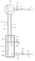
オイルポンプ120と施設園芸用ハウスの屋外に設置された油タンク200との間には、燃料配管140が配設されている。燃料配管140は、油タンク200とケーシング101の一端面の下部に取り付けられたサービスタンク150との間が、油タンク200側の第1フレキシブル管141、地中に埋設された主配管142、サービスタンク150側の第2フレキシブル管143により接続されている。第1フレキシブル管141の油タンク200寄りには送油バルブ161が、第2フレキシブル管143の主配管142寄りにはストップバルブ162が設けられ、第2フレキシブル管143のサービスタンク150寄りにはオイルストレーナ170が設けられている。
A
サービスタンク150は、油タンク200からオイルポンプ120に送る燃料を一時的に貯留する円筒形の装置であり、図2に示すように、タンク本体151の側面下端付近に第2フレキシブル管143の出口が接続されている。サービスタンク150とオイルポンプ120の間には往路管144と復路管145が設けられている。図2に示すように、往路管144の下端の燃料導入部144aはサービスタンク150内の下部であって底面付近に位置し、復路管145の下端の燃料戻り部145aはサービスタンク150内の上部に位置している。図3に示すように、往路管144はオイルポンプ120の作動によりサービスタンク150内に一時貯留された燃料Oを吸い上げてオイルポンプ120に送り、復路管145はオイルポンプ120に送られた燃料のうち、ノズル111に送られなかった燃料をサービスタンク150内に戻す役目をそれぞれ果たしている。
The
なお、オイルポンプ120に送られた燃料は、図3に示すように、電磁弁112の開操作により、ノズル111へと送られ、ノズル111から火炉内に噴射されて着火により高温の燃焼ガスを生成し、ハウス内空気との熱交換に用いられる。電磁弁112の全閉時には、オイルポンプ120に送られた燃料は、復路管145を介してサービスタンクに戻されるようになっている。
As shown in FIG. 3, the fuel sent to the
サービスタンク150内には、下部に燃料貯留部152が形成されるとともに、上部に圧力緩衝部153が形成されている。この圧力緩衝部153は、燃料配管140、特にオイルポンプ120とストップバルブ162間の燃料配管140の管内圧力を緩衝するためのもので、夏場の炎天下など、燃料配管140、特にオイルポンプ120とストップバルブ162間の燃料配管140内の油温度上昇に伴って熱膨張(A重油の体積膨張率0.0007/℃)により管内圧力が上昇する。管内圧力の上昇によりサービスタンク150内の下部燃料貯留部151の燃料容積が増加するが、図2に示すように、管内の圧力上昇による燃料の容積増加分△Vをサービスタンク150内の上部の圧力緩衝部152が吸収し、管内圧力が緩衝される結果、燃料配管140の途中の、オイルポンプ120のシール部やオイルストレーナ170のシール部、あるいは燃料配管140の接続シール部からの燃料油の漏出を防止できる。
In the
圧力緩衝部153は、サービスタンク150内の上部に空気室(空気溜まり)を形成することにより構成できる。サービスタンク150内の上部に圧力緩衝部153を形成する方法については、後述する。サービスタンク150の側面上部にはエア抜きバルブ163が設けられている。このエア抜きバルブ163は、主にサービスタンク150の上部に圧力緩衝部152を形成し、その容積を調整する際に用いる。
The pressure buffering
なお、サービスタンク150の高さ位置は、図1に示すように、油タンク200の第1フレキシブル管141につながる燃料出口の高さ位置よりも低い位置に配置され、したがって、油タンク200から円滑に燃料がサービスタンク150に供給されるようになっている。
As shown in FIG. 1, the height position of the
次に、以上のように構成された施設園芸用温風暖房機100の使用手順および作用について、以下に説明する。
Next, the usage procedure and operation of the facility horticulture
施設園芸用ハウス内に施設園芸用温風暖房機100を新設した場合等は、図1に示す送油バルブ161およびストップバルブ162をそれぞれ開き、油タンク200内の燃料を、燃料配管140を通してサービスタンク150内に一次貯留する必要がある。燃料がサービスタンク150内に貯留されるに先立ち、オイルポンプ120を作動させると、燃料配管140(第1フレキシブル管141、主配管142、第2フレキシブル管143、往路管144、復路管145)内に滞留するエアが、オイルポンプ120の作動によりサービスタンク150内に導入される。そこで、エア抜きバルブ163を開き、サービスタンク150内のエアを徐々に排気し、同時に油タンク200内から、燃料が燃料配管140(第1フレキシブル管141、主配管142、第2フレキシブル管143)を通して、サービスタンク150内の下部に導入され、徐々に貯留される。
When the facility horticulture
サービスタンク150内の下部に貯留された燃料の上面が上昇し、往路管144の燃料導入部144aが十分に燃料内に没し、サービスタンク150内の高さの約2/3以上に達したら、上部に空気溜まりを残して、エア抜きバルブ163を全閉する。これにより、図2に示すように、サービスタンク150内の下部に貯留された燃料から構成される燃料貯留部152が形成され、また、サービスタンク150内の上部に空気溜まりによる圧力緩衝部153が形成される。これにより、施設園芸用暖房機100の暖房運転の準備が完了する。
When the upper surface of the fuel stored in the lower part in the
施設園芸用暖房機100の暖房運転においては、図3に示すように、オイルポンプ120を作動させ、電磁弁112を開操作することにより、サービスタンク150内から往路管144を通してオイルポンプ120側へ吸い上げられた燃料Oが、バーナ110のノズル111に送られ、着火により高温の燃焼ガスが生成され、ケーシング101内に取り込まれたハウス内空気と熱交換され、温風がハウス内に供給される。ノズル111に送られなかった燃料Oはオイルポンプ120から復路管145を通してサービスタンク150内に戻される。上記温風暖房機100は、施設園芸用ハウスの加温のため、通常10月から翌年の5月頃までの期間使用される。
In the heating operation of the
上記使用期間以外では、機械のメンテナンス後、電気の遮断と燃料配管140のストップバルブ162の全閉により保管管理される。夏場の炎天下では、ハウス内が高温状態(約70〜80℃)となり、なかでも、ハウス内に位置する燃料配管140の露出部分(オイルポンプ120とストップバルブ162間)は、直射日光が直接あたり、その輻射熱で燃料配管140内の油温度が上昇し、熱膨張により燃料配管140内の管内圧力が上昇する。燃料配管140は閉回路となっており、燃料配管140、特にオイルポンプ120とストップバルブ162間の燃料容積が増加する。この燃料容積の増加分△Vは、図2の点線に示すように、サービスタンク150内の上部の圧力緩衝部(空気溜まり)153により吸収され、管内圧力が緩衝される。
Except for the above-mentioned period of use, after maintenance of the machine, storage management is performed by shutting off electricity and fully closing the
管内圧力がサービスタンク150内の圧力緩衝部153により吸収される結果、燃料配管140の途中の各シール部、例えばオイルポンプ120のシール部やオイルストレーナ170のシール部、あるいは燃料配管140の接続シール部に圧力が集中して燃料油が漏出されることが防止される。
As a result of the pressure in the pipe being absorbed by the
サービスタンク150内の圧力緩衝部153の容積は、エア抜きバルブ163の開閉操作により、適宜調整することができる。新たな設備の増設を必要とせず、既存のサービスタンク150をそのまま活用して圧力緩衝部153を形成できるから、コストアップを抑制することができるし、オイルポンプ120のシール部やオイルストレーナ170のシール部、あるいは燃料配管140の接続シール部の損傷を防止できるから、施設園芸用温風暖房機100の耐久性を向上させ、メンテナンス費用を削減することができる。
The volume of the
また、夏場等のオフシーズン時に燃料油の漏出を防止して、ハウス内土壌や河川を燃料油で汚染させる事態を招くおそれがなくなる。 In addition, leakage of fuel oil is prevented during off-season such as in summer, and there is no possibility of causing a situation where soil in the house or river is contaminated with fuel oil.
本発明者は、上記の施設園芸用温風暖房機について、サービスタンクの圧力緩衝部による作用効果を確認した。ここで、実施例の施設園芸用温風暖房機に付属するサービスタンク内の全容積は0.454Lで、サービスタンクの全容積中、下部の燃料貯留部を0.368L、上部の圧力緩衝部(空気溜まり)を0.086Lの割合に設定した。オイルポンプからストップバルブまでの液封燃料(燃料配管とサービスタンクを含む)の全容積は0.890Lであった。夏場の環境設定温度を70℃と仮定した場合、A重油の標準温度15℃、A重油の体積膨張率0.0007/℃により、夏場に想定される燃料の膨張容量△Vは、[液封燃料の全容積]×[温度差]×[体積膨張率]の計算式により、0.890×55×0.0007≒0.034Lである。サービスタンクの圧力緩衝部の容積は0.086Lであり、想定される膨張容量△Vの約2.5倍以上あることから、夏場の炎天下において、十分な圧力緩衝効果を期待できることが分かった。このことから、サービスタンクの圧力緩衝部の容量は、オイルポンプからストップバルブまでの液封燃料(燃料配管とサービスタンクを含む)の全容積の少なくとも1/25以上、好ましくは、1/15〜1/8の範囲内であることが望ましい。 This inventor confirmed the effect by the pressure buffer part of a service tank about said facility gardening warm air heater. Here, the total volume in the service tank attached to the hot air heater for horticulture in the embodiment is 0.454L, and the lower fuel storage portion is 0.368L in the total volume of the service tank, and the upper pressure buffering portion. (Air pocket) was set to a ratio of 0.086L. The total volume of liquid seal fuel (including fuel piping and service tank) from the oil pump to the stop valve was 0.890 L. Assuming that the environmental setting temperature in summer is 70 ° C., the fuel expansion capacity ΔV assumed in the summer is [liquid seal] due to the standard temperature of heavy fuel oil A of 15 ° C. and the volume expansion rate of heavy fuel oil of 0.0007 / ° C. From the calculation formula of “total volume of fuel” × [temperature difference] × [volume expansion coefficient], 0.890 × 55 × 0.0007≈0.034L. Since the volume of the pressure buffering portion of the service tank is 0.086 L, which is about 2.5 times or more than the expected expansion capacity ΔV, it has been found that a sufficient pressure buffering effect can be expected in the hot summer. From this, the capacity of the pressure buffering part of the service tank is at least 1/25 or more of the total volume of liquid seal fuel (including fuel piping and service tank) from the oil pump to the stop valve, preferably 1/15 to It is desirable to be within a range of 1/8.
本発明に係る施設園芸用温風暖房機は、施設園芸用ハウス内に温風を供給してハウス内を暖房する温風暖房機として利用可能である。 The hot air heater for facility horticulture according to the present invention can be used as a hot air heater for supplying warm air into the facility horticulture house to heat the house.
1,100 施設園芸用温風暖房機
2,101 ケーシング
3,110 バーナ
4,120 オイルポンプ
5,130 送風機
6,140 燃料配管
7,144 往路管
8,145 復路管
9,150 サービスタンク
10,161 送油バルブ
11,162 ストップバルブ
12,170 オイルストレーナ
20,200 油タンク
111 ノズル
112 電磁弁
141 第1フレキシブル管
142 主配管
143 第2フレキシブル管
144a 往路管の燃料導入部
145a 復路管の燃料戻り部
151 サービスタンク本体
152 燃料貯留部
153 圧力緩衝部
163 エア抜きバルブ
1,100 Hot air heater for horticulture 2,101 Casing 3,110 Burner 4,120 Oil pump 5,130 Blower 6,140 Fuel pipe 7,144 Outward pipe 8,145 Return pipe 9,150 Service tank 10,161
Claims (5)
前記オイルポンプとサービスタンクの間の燃料配管は、サービスタンク内の燃料貯留部から燃料が吐出される往路管とオイルポンプから燃料が戻される復路管とから構成されるとともに、前記サービスタンク内の燃料貯留部を除く上部空間に燃料配管の管内圧力を緩衝する圧力緩衝部が設けられていることを特徴とする施設園芸用温風暖房機。 A burner is provided on one end surface of the casing, and a fuel pipe is provided between an oil pump that supplies fuel to the burner and an oil tank that is installed outside the facility horticulture house. In facility horticulture hot air heaters equipped with service tanks to temporarily store fuel,
The fuel pipe between the oil pump and the service tank is composed of an outward pipe from which fuel is discharged from a fuel reservoir in the service tank and a return pipe from which the fuel is returned from the oil pump. A warm air heater for facility horticulture, characterized in that a pressure buffering section for buffering the pressure in the fuel pipe is provided in an upper space excluding the fuel storage section.
Priority Applications (1)
| Application Number | Priority Date | Filing Date | Title |
|---|---|---|---|
| JP2011036632A JP5693995B2 (en) | 2011-02-23 | 2011-02-23 | Hot air heater for horticulture |
Applications Claiming Priority (1)
| Application Number | Priority Date | Filing Date | Title |
|---|---|---|---|
| JP2011036632A JP5693995B2 (en) | 2011-02-23 | 2011-02-23 | Hot air heater for horticulture |
Publications (2)
| Publication Number | Publication Date |
|---|---|
| JP2012170412A true JP2012170412A (en) | 2012-09-10 |
| JP5693995B2 JP5693995B2 (en) | 2015-04-01 |
Family
ID=46973919
Family Applications (1)
| Application Number | Title | Priority Date | Filing Date |
|---|---|---|---|
| JP2011036632A Active JP5693995B2 (en) | 2011-02-23 | 2011-02-23 | Hot air heater for horticulture |
Country Status (1)
| Country | Link |
|---|---|
| JP (1) | JP5693995B2 (en) |
Citations (15)
| Publication number | Priority date | Publication date | Assignee | Title |
|---|---|---|---|---|
| US4109395A (en) * | 1976-10-28 | 1978-08-29 | Huang Barney K | Greenhouse, drying, storing nursery system |
| JPS58113866U (en) * | 1982-01-28 | 1983-08-03 | マツダ株式会社 | engine fuel supply system |
| US4609346A (en) * | 1985-06-24 | 1986-09-02 | Siccardi Frank J | Environmental control system for large volume structures |
| JPH01211435A (en) * | 1988-02-18 | 1989-08-24 | Daiko Kk | Plant growing system using heat of combustion of product oil from waste plastic |
| JPH0285249U (en) * | 1988-12-09 | 1990-07-04 | ||
| JPH05133610A (en) * | 1991-11-12 | 1993-05-28 | Sanshu Sangyo Kk | Hot air space heater |
| JPH05336847A (en) * | 1992-05-15 | 1993-12-21 | Nepon Kk | Method for heating greenhouse for protected horticulture |
| JPH0646678A (en) * | 1992-04-10 | 1994-02-22 | Gye-Sung Wi | Comprehensive system for controlling cultivation of crops |
| JPH08337299A (en) * | 1995-06-07 | 1996-12-24 | Nissei Oobaru Kk | Liquid feeding device |
| JPH09301491A (en) * | 1996-05-08 | 1997-11-25 | Minoru Tsuha | Liquid fuel tank |
| JP2003035214A (en) * | 2001-07-23 | 2003-02-07 | Toyota Motor Corp | Evaporated fuel control device for fuel tank |
| JP2004100622A (en) * | 2002-09-11 | 2004-04-02 | Honda Motor Co Ltd | Evaporated fuel processing device |
| JP2007127106A (en) * | 2005-11-07 | 2007-05-24 | Suzuki Motor Corp | Treatment device for evaporative fuel in portable fuel-tank for outboard engine |
| JP2008178298A (en) * | 2007-01-23 | 2008-08-07 | Sunao Denki Kk | Greenhouse heating apparatus |
| JP2009215993A (en) * | 2008-03-11 | 2009-09-24 | Denso Corp | Fuel injection device |
-
2011
- 2011-02-23 JP JP2011036632A patent/JP5693995B2/en active Active
Patent Citations (15)
| Publication number | Priority date | Publication date | Assignee | Title |
|---|---|---|---|---|
| US4109395A (en) * | 1976-10-28 | 1978-08-29 | Huang Barney K | Greenhouse, drying, storing nursery system |
| JPS58113866U (en) * | 1982-01-28 | 1983-08-03 | マツダ株式会社 | engine fuel supply system |
| US4609346A (en) * | 1985-06-24 | 1986-09-02 | Siccardi Frank J | Environmental control system for large volume structures |
| JPH01211435A (en) * | 1988-02-18 | 1989-08-24 | Daiko Kk | Plant growing system using heat of combustion of product oil from waste plastic |
| JPH0285249U (en) * | 1988-12-09 | 1990-07-04 | ||
| JPH05133610A (en) * | 1991-11-12 | 1993-05-28 | Sanshu Sangyo Kk | Hot air space heater |
| JPH0646678A (en) * | 1992-04-10 | 1994-02-22 | Gye-Sung Wi | Comprehensive system for controlling cultivation of crops |
| JPH05336847A (en) * | 1992-05-15 | 1993-12-21 | Nepon Kk | Method for heating greenhouse for protected horticulture |
| JPH08337299A (en) * | 1995-06-07 | 1996-12-24 | Nissei Oobaru Kk | Liquid feeding device |
| JPH09301491A (en) * | 1996-05-08 | 1997-11-25 | Minoru Tsuha | Liquid fuel tank |
| JP2003035214A (en) * | 2001-07-23 | 2003-02-07 | Toyota Motor Corp | Evaporated fuel control device for fuel tank |
| JP2004100622A (en) * | 2002-09-11 | 2004-04-02 | Honda Motor Co Ltd | Evaporated fuel processing device |
| JP2007127106A (en) * | 2005-11-07 | 2007-05-24 | Suzuki Motor Corp | Treatment device for evaporative fuel in portable fuel-tank for outboard engine |
| JP2008178298A (en) * | 2007-01-23 | 2008-08-07 | Sunao Denki Kk | Greenhouse heating apparatus |
| JP2009215993A (en) * | 2008-03-11 | 2009-09-24 | Denso Corp | Fuel injection device |
Also Published As
| Publication number | Publication date |
|---|---|
| JP5693995B2 (en) | 2015-04-01 |
Similar Documents
| Publication | Publication Date | Title |
|---|---|---|
| JP2014223050A (en) | Greenhouse heater with power generation function using heat for heating added | |
| JP5693995B2 (en) | Hot air heater for horticulture | |
| CN102778039A (en) | Non overhead tank automatic oil-supplementation exhaust heat-supply flow system for organic heat carrier furnace | |
| CN205351757U (en) | Fuel gas heating stove | |
| KR102015582B1 (en) | Combustion apparatus using direct injection for lpg | |
| KR20110024268A (en) | Heating system of using molten salt | |
| CN201488312U (en) | Double-water tank solar water heater | |
| CN203561095U (en) | Anti-freezing system of solar water heater | |
| CN205156316U (en) | Environmental protection formula gas heater | |
| KR101248770B1 (en) | Central heating system for apartment | |
| CN201569159U (en) | Overflow instantaneous liquid heating device and warm-cold dual-purpose machine with same | |
| KR101053107B1 (en) | Condensate Recovery System | |
| JP2010223539A (en) | Wood stove device and wood stove heating system | |
| KR101365724B1 (en) | A heating apparatus of heat pipe for boiler combination stove | |
| KR101584101B1 (en) | Multi functional boiler that uses wood pellets | |
| WO2021112785A1 (en) | Warehouse system in which hot water obtained from solar panels is used for weed control | |
| RU67232U1 (en) | OUTDOOR BOILER | |
| CN101701748B (en) | Overflowing instant heating type liquid heating device and warm and hot dual-purpose machine using same | |
| CN205690514U (en) | PTC electric ceramic heating vacuum superconductive heating pipe | |
| CN209165768U (en) | A kind of water covers formula power economized boiler | |
| KR20140003966A (en) | Pan biomass energy supplying equipment and biomass boiler of continuous heating system | |
| KR101340210B1 (en) | De-frost system for apartment boiler exhaust gas tube | |
| CN210801118U (en) | Fuel oil steam generator capable of recovering waste heat | |
| CN203310068U (en) | Energy-saving water heater | |
| EP3677864A1 (en) | Climate mitigator |
Legal Events
| Date | Code | Title | Description |
|---|---|---|---|
| A621 | Written request for application examination |
Free format text: JAPANESE INTERMEDIATE CODE: A621 Effective date: 20140210 |
|
| A977 | Report on retrieval |
Free format text: JAPANESE INTERMEDIATE CODE: A971007 Effective date: 20141125 |
|
| TRDD | Decision of grant or rejection written | ||
| A01 | Written decision to grant a patent or to grant a registration (utility model) |
Free format text: JAPANESE INTERMEDIATE CODE: A01 Effective date: 20150128 |
|
| A61 | First payment of annual fees (during grant procedure) |
Free format text: JAPANESE INTERMEDIATE CODE: A61 Effective date: 20150204 |
|
| R150 | Certificate of patent or registration of utility model |
Ref document number: 5693995 Country of ref document: JP Free format text: JAPANESE INTERMEDIATE CODE: R150 |
|
| R250 | Receipt of annual fees |
Free format text: JAPANESE INTERMEDIATE CODE: R250 |
|
| R250 | Receipt of annual fees |
Free format text: JAPANESE INTERMEDIATE CODE: R250 |
|
| R250 | Receipt of annual fees |
Free format text: JAPANESE INTERMEDIATE CODE: R250 |
|
| R250 | Receipt of annual fees |
Free format text: JAPANESE INTERMEDIATE CODE: R250 |
|
| R250 | Receipt of annual fees |
Free format text: JAPANESE INTERMEDIATE CODE: R250 |
|
| R250 | Receipt of annual fees |
Free format text: JAPANESE INTERMEDIATE CODE: R250 |
|
| R250 | Receipt of annual fees |
Free format text: JAPANESE INTERMEDIATE CODE: R250 |