JP2012170320A - Vacuum circuit breaker terminal and vacuum circuit breaker having the same - Google Patents
Vacuum circuit breaker terminal and vacuum circuit breaker having the same Download PDFInfo
- Publication number
- JP2012170320A JP2012170320A JP2012024044A JP2012024044A JP2012170320A JP 2012170320 A JP2012170320 A JP 2012170320A JP 2012024044 A JP2012024044 A JP 2012024044A JP 2012024044 A JP2012024044 A JP 2012024044A JP 2012170320 A JP2012170320 A JP 2012170320A
- Authority
- JP
- Japan
- Prior art keywords
- terminal
- circuit breaker
- outer diameter
- vacuum circuit
- guide member
- Prior art date
- Legal status (The legal status is an assumption and is not a legal conclusion. Google has not performed a legal analysis and makes no representation as to the accuracy of the status listed.)
- Pending
Links
Images


Classifications
-
- H—ELECTRICITY
- H01—ELECTRIC ELEMENTS
- H01H—ELECTRIC SWITCHES; RELAYS; SELECTORS; EMERGENCY PROTECTIVE DEVICES
- H01H33/00—High-tension or heavy-current switches with arc-extinguishing or arc-preventing means
- H01H33/60—Switches wherein the means for extinguishing or preventing the arc do not include separate means for obtaining or increasing flow of arc-extinguishing fluid
- H01H33/66—Vacuum switches
- H01H33/6606—Terminal arrangements
-
- H—ELECTRICITY
- H02—GENERATION; CONVERSION OR DISTRIBUTION OF ELECTRIC POWER
- H02B—BOARDS, SUBSTATIONS OR SWITCHING ARRANGEMENTS FOR THE SUPPLY OR DISTRIBUTION OF ELECTRIC POWER
- H02B11/00—Switchgear having carriage withdrawable for isolation
- H02B11/02—Details
- H02B11/04—Isolating-contacts, e.g. mountings or shieldings
-
- H—ELECTRICITY
- H02—GENERATION; CONVERSION OR DISTRIBUTION OF ELECTRIC POWER
- H02B—BOARDS, SUBSTATIONS OR SWITCHING ARRANGEMENTS FOR THE SUPPLY OR DISTRIBUTION OF ELECTRIC POWER
- H02B11/00—Switchgear having carriage withdrawable for isolation
- H02B11/12—Switchgear having carriage withdrawable for isolation with isolation by horizontal withdrawal
- H02B11/127—Withdrawal mechanism
-
- H—ELECTRICITY
- H01—ELECTRIC ELEMENTS
- H01H—ELECTRIC SWITCHES; RELAYS; SELECTORS; EMERGENCY PROTECTIVE DEVICES
- H01H1/00—Contacts
- H01H1/12—Contacts characterised by the manner in which co-operating contacts engage
- H01H1/36—Contacts characterised by the manner in which co-operating contacts engage by sliding
- H01H1/38—Plug-and-socket contacts
Abstract
Description
本発明は、真空回路遮断器に関し、特に、試験位置で遮断器本体の第1端子とクレードルの第2端子との間の距離が近くても電気的絶縁性を確保することができ、端子の接続時に発生する付勢荷重による端子の衝撃を最小限に抑え、端子の接離時に遮断器本体の垂直振動とそれによる騒音の発生を最小限に抑えることのできる真空回路遮断器用端子及びその端子を有する真空回路遮断器に関する。 The present invention relates to a vacuum circuit breaker, and in particular, electrical insulation can be ensured even when the distance between the first terminal of the breaker body and the second terminal of the cradle is close at the test position. Terminal for vacuum circuit breaker that can minimize the impact of the terminal due to the urging load generated at the time of connection, and minimize the vertical vibration of the circuit breaker body and the resulting noise when the terminal is connected and separated. It is related with the vacuum circuit breaker which has.
一般に、真空回路遮断器は、電力系統において、比較的高電圧の回路を開閉し、短絡電流などの事故電流に対して電力回路を遮断することにより、電力回路及び負荷機器を保護する電気機器である。 Generally, a vacuum circuit breaker is an electrical device that protects a power circuit and a load device by opening and closing a relatively high voltage circuit in the power system and shutting off the power circuit against an accident current such as a short circuit current. is there.
このような一般的な真空回路遮断器は、発電、変電、配電などの発電・送配電の箇所で広く使用されており、単独で使用されることもあるが、他の電力計と共に配電盤に収納されて使用される。 Such general vacuum circuit breakers are widely used in power generation / transmission / distribution locations such as power generation, substation, and distribution, and may be used independently, but they are housed in a switchboard together with other power meters. Have been used.
このような真空回路遮断器には引出形と固定形があり、本発明は引出形真空回路遮断器に関する。 Such a vacuum circuit breaker has a drawer type and a fixed type, and the present invention relates to a drawer type vacuum circuit breaker.
引出形真空回路遮断器は、クレードルと遮断器本体とを含む。 The drawer type vacuum circuit breaker includes a cradle and a breaker body.
クレードルは、配電盤に固定設置されるものであって、外部の電力回路に接続するための外部端子部と、遮断器本体側端子に接続するための内部端子部と、遮断器本体の移動経路を提供する底部と、遮断器本体の移動用車輪の収容及び転動をガイドするガイドレールを有する1対の側板部とを含む。 The cradle is fixedly installed on the switchboard, and has an external terminal part for connecting to an external power circuit, an internal terminal part for connecting to the circuit breaker body side terminal, and a moving path of the circuit breaker body. And a pair of side plates having a guide rail for guiding the accommodation and rolling of the moving wheel of the circuit breaker body.
遮断器本体は、交流3相(3極)の相毎に設けられる主回路部と、各主回路部に電気的に接続する導体からなる本体側端子とを含む。 The circuit breaker main body includes a main circuit portion provided for each phase of AC three-phase (three poles) and a main body side terminal formed of a conductor electrically connected to each main circuit portion.
ここで、主回路部は、絶縁性を有し、内部が真空状態であり、通常セラミック材料で形成される真空容器内に固定接点及び可動接点を内蔵した真空インタラプタを含む。主回路部は、相毎に設けられて3相の電力回路を開路又は閉路する機能を果たす。 Here, the main circuit portion includes a vacuum interrupter having insulating properties and having a vacuum inside, and having a fixed contact and a movable contact incorporated in a vacuum vessel usually formed of a ceramic material. The main circuit section is provided for each phase and functions to open or close the three-phase power circuit.
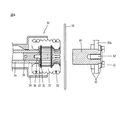
以下、このような真空回路遮断器における従来の端子の構成及び作用について図4を参照して説明する。 Hereinafter, the configuration and operation of a conventional terminal in such a vacuum circuit breaker will be described with reference to FIG.
図4は、従来の真空回路遮断器用端子の構成を示す縦断面図である。図4に示すように、従来の真空回路遮断器用端子は、第1端子30と第2端子40とを含む。
FIG. 4 is a longitudinal sectional view showing a configuration of a conventional vacuum circuit breaker terminal. As shown in FIG. 4, the conventional terminal for a vacuum circuit breaker includes a
図4において、符号50は、クレードル(図示せず)に支持されて第2端子40の前方に設置され、第1端子30が第2端子40に接続するように進入を許容する開放位置と第1端子30の進入を許容しない遮断位置とに昇降可能な安全シャッタ装置を示す。安全シャッタ装置50の開放位置又は遮断位置への動作は、遮断器本体(図示せず)の接続位置、試験位置、及び分離位置への移動と連動して行われる。ここで、接続位置は、遮断器本体側の第1端子30とクレードル側の第2端子40とが接続された位置である。試験位置は、遮断器本体側の第1端子30とクレードル側の第2端子40とが分離されているが、遮断器本体の制御部に開閉試験のための制御電源は供給される位置であって、安全シャッタ装置50は遮断位置にあり、第1端子30が安全シャッタ装置50に接近した、図4のような状態である。分離位置は、遮断器本体側の第1端子30とクレードル側の第2端子40とが分離されており、遮断器本体の制御部に開閉試験のための制御電源も遮断される位置であって、安全シャッタ装置50は遮断位置にあり、第1端子30が安全シャッタ装置50から遠ざかる位置に離隔する。
In FIG. 4,
安全シャッタ装置50の駆動装置の構成及び動作については、例えば本発明の出願人により出願された特許文献1(発明の名称:真空遮断器用クレードルのシャッタ駆動装置)を参照されたい。
For the configuration and operation of the drive device of the
一方、第1端子30は、遮断器本体に設置される端子であって、1対の支持板31、複数のフィンガコンタクタ32、複数のリングスプリング33などを含む。
On the other hand, the
第1端子30は、放射状に配置された複数のフィンガコンタクタ32がチューリップ形状であるので、チューリップ端子とも呼ばれる。
The
1対の支持板31は、複数のフィンガコンタクタ32を支持する手段であって、それぞれ所定の厚さを有するリング状の鉄製円盤で構成される。
The pair of
フィンガコンタクタ32は、フィンガ状に形成された導体接触子であって、支持板31の外周面に放射状に設置される。各フィンガコンタクタ32は、支持板31の外周面が挿入される1対の挿入溝部と、1対の接触突部と、複数のリングスプリング33が挿入される複数のスプリング収容部とを有する。
The
複数のリングスプリング33は、フィンガコンタクタ32のスプリング収容部に挿入されるように設置され、複数のフィンガコンタクタ32を中心方向に付勢する。フィンガコンタクタ32の接触突部が形成する第1端子30の内周面にクレードルの第2端子40の外周面が接触するように、第1端子30と第2端子40とが接続したとき、リングスプリング33の付勢力は、第1端子30と第2端子40との接触圧力を維持する作用をする。
The plurality of ring springs 33 are installed so as to be inserted into the spring accommodating portion of the
第1端子30は、図4に示すように、接続導体35、挿入部材36、加圧板37、結合ネジ38、及びハウジング34をさらに含んでもよい。
As shown in FIG. 4, the
ここで、接続導体35は、前述したように、真空回路遮断器の遮断器本体の主回路部側に延び、当該主回路部に電気的に接続する導体であって、パイプ状導体で構成されてもよい。
Here, as described above, the
挿入部材36、加圧板37、及び結合ネジ38は、複数のフィンガコンタクタ32を接続導体35に結合させるための構成部材である。
The
挿入部材36は、接続導体35内に挿入されてピン(符号なし)により接続導体35と接続される挿入部と、挿入部の一端部から外側に放射状に延設されるフランジ部とを有する。ここで、フランジ部は凹部を有する。
The
加圧板37は挿入部材36のフランジ部の凹部に挿入され、結合ネジ38を締めることによって、挿入部材36のフランジ部が加圧され、複数のフィンガコンタクタ32の一端部の内面(図4において、フィンガコンタクタ32の左側端部の内側面)に密着して接触する。
The
結合ネジ38は、加圧板37の中心部を貫通して挿入部材36の挿入部内に挿入されて、加圧板37により挿入部材36のフランジ部を複数のフィンガコンタクタ32の一端部の内面に密着させる手段である。
The
ハウジング34は、接続導体35、挿入部材36、加圧板37、及び結合ネジ38を内部に収容し、各フィンガコンタクタ32の一部を収容する筐体を提供する。
The
一方、第2端子40は、クレードルの後方垂直板20aに固定設置される端子であって、ブッシング形状の電気導体で構成される。後方垂直板20aの前面と背面で第2端子40の上下部面に密着して保持する1対の保持板41と、当該保持板41を後方垂直板20aに固定的に結合する接続ボルト42とにより、第2端子40は、上下方向に揺動しないようにクレードルの後方垂直板20aに固定されて支持される。
On the other hand, the
図4において、符号43はネジ具である。
In FIG. 4, the code |
また、第2端子40の外径は、第1端子30の各フィンガコンタクタ32の内側面が形成する第1端子30の内周面の内径より大きい。
Further, the outer diameter of the
ところが、第2端子40及び第1端子30の試験位置から接続位置への動作時、第1端子30の各フィンガコンタクタ32は、第2端子40との衝突により短時間で半径方向外側に広がり、このとき、第1端子30を有する遮断器本体は、第1端子30を有する部分が上下に垂直振動し、従って、振動騒音が発生し、端子部と遮断器本体の損傷を起こすことがあるという問題があった。
However, during the operation of the
また、接続位置への動作時にフィンガコンタクタ32が半径方向外側に広がるので、フィンガコンタクタ32と第2端子40の外周面との接触力を維持して電気的抵抗を減少させるためには、リングスプリング33に大きな付勢力が求められるという問題があった。
In addition, since the
さらに、従来の真空回路遮断器用端子においては、試験位置で予め定められた第1端子30と第2端子40との間の電気的絶縁距離を確保するために、第2端子40を短く形成しなければならず、従って、第2端子40の先端部の前面は外周面と略直角をなすように構成しなければならなかった。このような第2端子40の構成は、接続位置への動作初期に第1端子30と衝突を起こし、遮断器本体における第1端子30を有する部分の上下の大きな垂直振動とそれによる騒音を発生させ、端子部と遮断器本体の損傷を起こすという問題があった。
Further, in the conventional vacuum circuit breaker terminal, the
遮断器本体における第1端子30を有する部分の上下の大きな垂直振動とそれによる騒音は、遮断器本体を接続位置から試験位置に後退させるときにも発生していた。
Large vertical vibrations at the top and bottom of the part having the
本発明は、このような従来技術の問題を解決するためになされたもので、本発明の一目的は、試験位置で遮断器本体側端子とクレードル側端子間の電気的絶縁性を確保しながらも、遮断器本体側端子とクレードル側端子の接離時の衝撃と振動を最小限に抑えられる真空回路遮断器用端子を提供することにある。 The present invention was made to solve such problems of the prior art, and one object of the present invention is to ensure electrical insulation between the circuit breaker body side terminal and the cradle side terminal at the test position. Another object of the present invention is to provide a vacuum circuit breaker terminal capable of minimizing shock and vibration during contact between the breaker body side terminal and the cradle side terminal.
本発明の他の目的は、試験位置で遮断器本体側端子とクレードル側端子間の電気的絶縁性を確保しながらも、遮断器本体側端子とクレードル側端子の接離時の衝撃と振動を最小限に抑えられる端子を有する真空回路遮断器を提供することにある。 Another object of the present invention is to provide shock and vibration during contact / separation between the breaker body side terminal and the cradle side terminal while ensuring electrical insulation between the breaker body side terminal and the cradle side terminal at the test position. The object is to provide a vacuum circuit breaker having terminals that are minimized.
上記の本発明の一目的は、複数の支持リング、前記支持リングの周囲に放射状に配置される複数のフィンガコンタクタ、及び前記フィンガコンタクタを中心方向に付勢するように前記フィンガコンタクタの外周面に接触して設置されるリング状スプリングを備える第1端子と、前記第1端子のフィンガコンタクタの内周面により形成される前記第1端子の内径より大きい外径を有し、ブッシング形状に形成された電気導体で構成される第2端子と、前記第1端子と前記第2端子とが分離されたときに前記第2端子の電気的絶縁性が向上するように、前記第2端子の先端部に着脱可能に固定設置され、電気的絶縁性を有し、前記第2端子から遠ざかるほど外径が小さくなるようにテーパ状に形成される絶縁ガイド部材とを含む、本発明による真空回路遮断器用端子を提供することにより達成される。 One object of the present invention is to provide a plurality of support rings, a plurality of finger contactors arranged radially around the support ring, and an outer peripheral surface of the finger contactor so as to urge the finger contactors in a central direction. A first terminal having a ring-shaped spring installed in contact with an outer diameter larger than an inner diameter of the first terminal formed by an inner peripheral surface of a finger contactor of the first terminal, and formed in a bushing shape. The tip of the second terminal so that the electrical insulation of the second terminal is improved when the second terminal constituted by the electrical conductor and the first terminal and the second terminal are separated from each other. And an insulating guide member that is fixedly detachably attached to the insulating guide member and has an electrical insulation property, and is formed in a tapered shape so that the outer diameter decreases as the distance from the second terminal increases. It is achieved by providing a circuit breaker terminal.
上記の本発明の他の目的は、電力回路の電源側及び電気的負荷側電線に接続可能な端子部、移動経路を提供する底部を有するクレードルと、3つの各交流極の回路を開路又は閉路する複数の主回路部を有し、前記クレードルの端子部に接続される第1位置と前記クレードルの端子部から分離される第2位置とに前記クレードルの底部の移動経路上を移動可能な遮断器本体と、複数の支持リング、前記支持リングの周囲に放射状に配置される複数のフィンガコンタクタ、及び前記フィンガコンタクタを中心方向に付勢するように前記フィンガコンタクタの外周面に接触して設置されるリング状スプリングを備え、前記クレードルと前記遮断器本体のいずれか一方に設置される第1端子と、前記第1端子のフィンガコンタクタの内周面により形成される前記第1端子の内径より大きい外径を有し、ブッシング形状に形成された電気導体で構成され、前記クレードルと前記遮断器本体のうち前記第1端子が設置されない方に設置される第2端子と、前記第1端子と前記第2端子とが分離されたときに前記第2端子の電気的絶縁性が向上するように、前記第2端子の先端部に着脱可能に固定設置され、電気的絶縁性を有し、前記第2端子から遠ざかるほど外径が小さくなるようにテーパ状に形成される絶縁ガイド部材とを含む、本発明による真空回路遮断器を提供することにより達成される。 Another object of the present invention is to open or close a circuit of a terminal part connectable to a power source side and an electric load side electric wire of a power circuit, a cradle having a bottom part that provides a moving path, and three AC pole circuits. And a plurality of main circuit sections that are movable, and are movable on a moving path of a bottom part of the cradle between a first position connected to the terminal part of the cradle and a second position separated from the terminal part of the cradle. A main body, a plurality of support rings, a plurality of finger contactors arranged radially around the support ring, and an outer peripheral surface of the finger contactor so as to urge the finger contactors in a central direction. A ring-shaped spring, and a first terminal installed on one of the cradle and the breaker body, and an inner peripheral surface of the finger contactor of the first terminal A second conductor that has an outer diameter larger than the inner diameter of the first terminal and is formed of an electric conductor formed in a bushing shape, and is installed on a side of the cradle and the circuit breaker body on which the first terminal is not installed. A terminal, and the first terminal and the second terminal are detachably fixed and installed at the tip of the second terminal so that the electrical insulation of the second terminal is improved when the terminal is separated from the second terminal; This is achieved by providing a vacuum circuit breaker according to the present invention including an insulating guide member having a mechanical insulation property and having a tapered shape so that the outer diameter decreases as the distance from the second terminal increases.
本発明の好ましい一態様によれば、前記絶縁ガイド部材における外径が最も大きい部分の外径は、前記第2端子の外径より大きくなく、前記絶縁ガイド部材における外径が最も小さい自由端部の外径は、前記第1端子の内径より小さいか等しい。 According to a preferred aspect of the present invention, the outer diameter of the portion having the largest outer diameter in the insulating guide member is not larger than the outer diameter of the second terminal, and the free end portion having the smallest outer diameter in the insulating guide member. Has an outer diameter smaller than or equal to the inner diameter of the first terminal.
本発明の好ましい他の態様によれば、前記絶縁ガイド部材における外径が最も小さい自由端部の外径は、前記第1端子の内径より小さいか等しい。 According to another preferable aspect of the present invention, the outer diameter of the free end portion having the smallest outer diameter in the insulating guide member is smaller than or equal to the inner diameter of the first terminal.
本発明の好ましいさらに他の態様によれば、前記絶縁ガイド部材における外径が最も大きい部分の外径は、前記第2端子の外径より大きくなく、前記第1端子の内径より大きい。 According to still another preferred aspect of the present invention, the outer diameter of the portion of the insulating guide member having the largest outer diameter is not larger than the outer diameter of the second terminal, but larger than the inner diameter of the first terminal.
本発明の好ましいさらに他の態様によれば、本発明による真空回路遮断器は、前記第2端子の先端部と前記絶縁ガイド部材とを結合するための結合ボルトをさらに含んでもよく、前記第2端子は前面に凹部を有し、これに対応するように、前記絶縁ガイド部材は後方に突出部を有し、前記第2端子の前面の凹部に前記絶縁ガイド部材の後方の突出部を挿入することにより、前記第2端子と前記絶縁ガイド部材とを結合するようにしてもよい。 According to still another preferred aspect of the present invention, the vacuum circuit breaker according to the present invention may further include a coupling bolt for coupling the distal end portion of the second terminal and the insulating guide member. The terminal has a concave portion on the front surface, and the insulating guide member has a protruding portion on the rear side, and the protruding portion on the rear side of the insulating guide member is inserted into the concave portion on the front surface of the second terminal. Accordingly, the second terminal and the insulating guide member may be coupled.
本発明による真空回路遮断器用端子及びその端子を有する真空回路遮断器においては、クレードル側の第2端子の先端部に接続された絶縁ガイド部材により、試験位置で遮断器本体側の第1端子とクレードル側の第2端子との電気的絶縁性が確保されるという利点を有する。また、絶縁ガイド部材の外周面が第2端子から遠ざかるほど外径が小さくなるテーパ面からなるので、第1端子と第2端子との接離時に衝撃と振動が最小限に抑えられるという利点を有する。 In the vacuum circuit breaker terminal and the vacuum circuit breaker having the terminal according to the present invention, the insulation guide member connected to the tip of the second terminal on the cradle side and the first terminal on the breaker body side at the test position There is an advantage that electrical insulation with the second terminal on the cradle side is ensured. In addition, since the outer peripheral surface of the insulating guide member is a tapered surface whose outer diameter decreases as the distance from the second terminal increases, the advantage that shock and vibration can be minimized when the first terminal and the second terminal are brought into contact with each other. Have.
以下、添付の図1〜図3を参照して、本発明の好ましい実施形態による真空回路遮断器用端子及びその端子を有する真空回路遮断器の構成と作用効果を説明する。 Hereinafter, with reference to attached FIGS. 1-3, the structure and effect of a vacuum circuit breaker terminal and a vacuum circuit breaker having the terminal according to a preferred embodiment of the present invention will be described.
図1に示すように、本発明の好ましい実施形態による真空回路遮断器は、クレードル200と遮断器本体100とを含む。
As shown in FIG. 1, the vacuum circuit breaker according to a preferred embodiment of the present invention includes a
クレードル200は、電力回路の電源側及び電気的負荷側電線に接続可能な端子部としての第2端子(図2及び図3の符号500参照)と、遮断器本体100に移動経路を提供する底部210とを有する。
The
遮断器本体100は、3つの各交流極の回路を開路又は閉路する複数、すなわち3つの主回路部110を有する。
The
遮断器本体100は、クレードル200の端子部(第2端子500)に接続される第1位置と、クレードル200の端子部(第2端子500)から分離される第2位置とに、クレードル200の底部210の移動経路上を移動することができる。
The
図1において、符号220は、クレードル200の第2端子500を支持する後方垂直板を示す。
In FIG. 1,
以下、図2を参照して、本発明の好ましい実施形態による真空回路遮断器の第1端子300及び第2端子500の構成を詳細に説明する。
Hereinafter, the configuration of the
本実施形態においては、第1端子300が遮断器本体100に設置されるが、第1端子300がクレードル200に設置される変形実施形態も可能である。もちろん、第1端子300がクレードル200に設置される場合、第2端子500は遮断器本体100に設置される。
In this embodiment, although the
第1端子300は、複数の支持リング360と、複数のフィンガコンタクタ320と、複数のリング状スプリング350とを含む。
The
複数の支持リング360は、複数のフィンガコンタクタ320を支持する手段であって、それぞれ所定の厚さを有するリング状の鉄製円盤で構成されてもよい。
The plurality of support rings 360 are means for supporting the plurality of
フィンガコンタクタ320は、フィンガ状に形成された電気導体接触子であって、支持リング360の周囲に放射状に配置される。各フィンガコンタクタ320は、支持リング360の外周面が挿入される1対の挿入溝部と、1対の接触突部320aと、複数のリングスプリング330が挿入される複数のスプリング収容部320bとを有する。ここで、1対の接触突部320aはフィンガコンタクタ320の両端部に位置し、1対の接触突部320aの間には中央平面部320cが設けられる。1対の接触突部320aは、第1端子300において第2端子500の外周面に直接接触する部分である。
The
フィンガコンタクタ320を中心方向に付勢するように、複数のリング状スプリング350は、フィンガコンタクタ320の外周面に接触して設置される。このようなリングスプリング350の付勢力は、フィンガコンタクタ320の接触突部320aが形成する第1端子300の内周面に第2端子500の外周面が接触して第1端子300と第2端子500とが接続されたとき、第1端子300と第2端子500との接触圧力を維持する作用をする。
The plurality of ring-shaped
また、第1端子300は、接続導体341及び挿入部材342を含む接続導体部340、加圧板390、結合ネジ380、及びハウジング370をさらに含んでもよい。
The
ここで、接続導体341は、前述したように、真空回路遮断器の遮断器本体100の主回路部110側に延び、主回路部110に電気的に接続する導体であって、パイプ状導体で構成されてもよい。
Here, as described above, the
挿入部材342、加圧板390、及び結合ネジ380は、複数のフィンガコンタクタ320を接続導体341に結合させるための構成部材である。
The
挿入部材342は、接続導体341内に挿入されてピン(符号なし)により接続導体341と接続される挿入部と、前記挿入部の一端部から外側に放射状に延設されるフランジ部とを有する。ここで、前記フランジ部は凹部を有する。
The
加圧板390は挿入部材342の前記フランジ部の凹部に挿入され、結合ネジ380を締めることによって、挿入部材342の前記フランジ部が加圧され、複数のフィンガコンタクタ320の一端部の内面(図2において、フィンガコンタクタ320の左側端部の内側面)に密着して接触する。
The
結合ネジ380は、加圧板390の中心部を貫通して挿入部材342の前記挿入部内に挿入されて、加圧板390により挿入部材342の前記フランジ部を複数のフィンガコンタクタ320の一端部の内面に密着させる手段である。
The
ハウジング370は、接続導体341、挿入部材342、加圧板390、及び結合ネジ380を内部に収容し、各フィンガコンタクタ320の一部を収容する筐体を提供する。
The
本実施形態においては、第2端子500がクレードル200、より具体的にはクレードル200の後方垂直板220に設置されるが、第2端子500が遮断器本体100に設置される変形実施形態も可能である。もちろん、第2端子500が遮断器本体100に設置される場合、第1端子300はクレードル200に設置される。
In the present embodiment, the
第2端子500は、第1端子300のフィンガコンタクタ320の内周面により形成される第1端子300の内径より大きい外径を有し、ブッシング形状に形成された電気導体で構成される。
The
図2及び図3に示すように、本発明の好ましい実施形態による真空回路遮断器用端子、又は当該端子を有する真空回路遮断器は、絶縁ガイド部材510をさらに含む。
As shown in FIGS. 2 and 3, the terminal for a vacuum circuit breaker according to a preferred embodiment of the present invention, or the vacuum circuit breaker having the terminal, further includes an insulating
絶縁ガイド部材510は、第1端子300と第2端子500とが分離された場合に第1端子300と第2端子500との電気的絶縁性を向上させる手段である。つまり、本発明の好ましい実施形態による真空回路遮断器が試験位置にあるとき、第1端子300と第2端子500とが分離されているが近接している状態で、絶縁ガイド部材510は、第1端子300と第2端子500に電気的絶縁性を提供する。
The insulating
絶縁ガイド部材510は、電気的絶縁性を有し、第2端子500の先端部に着脱可能に固定設置される。
The insulating
また、本発明の好ましい一態様によれば、絶縁ガイド部材510は、第2端子500から遠ざかるほど外径が小さくなるようにテーパ形状を有する。図2において、符号511は、絶縁ガイド部材510のテーパ状に形成された外周面を示す。
Further, according to a preferred aspect of the present invention, the insulating
また、本発明の好ましい一態様によれば、第2端子500が前面に凹部を有するブッシング形状に構成されることにより、これに対応するように、絶縁ガイド部材510は後方に突出部512を有する。従って、第2端子500の前面の凹部に絶縁ガイド部材510の後方の突出部512を挿入することにより、第2端子500と絶縁ガイド部材510とを結合することができる。
In addition, according to a preferred aspect of the present invention, the
さらに、図2を参照すると、本発明の好ましい一態様において、絶縁ガイド部材510における外径が最も小さい自由端部の外径Dは、第1端子300の内径d2より小さいか等しい。
Furthermore, referring to FIG. 2, in a preferred embodiment of the present invention, the outer diameter D of the free end portion having the smallest outer diameter in the insulating
従って、本発明の好ましい実施形態による真空回路遮断器においては、接続位置に進むために遮断器本体100の第1端子300がクレードル200の第2端子500に接続される際に、第1端子300と第2端子500との接触衝撃を最小限に抑えることができ、接続初期に第1端子300が上下に垂直振動する現象とそれによる騒音も防止することができ、第1端子300と第2端子500との接続を円滑に行うことができる。
Therefore, in the vacuum circuit breaker according to the preferred embodiment of the present invention, when the
さらに、図2を参照すると、本発明の好ましい一態様において、絶縁ガイド部材510における外径が最も大きい部分の外径(図2において右端部分の外径)は、第2端子500の外径より大きくなく、第1端子300の内径d2よりは大きい。
Further, referring to FIG. 2, in a preferred embodiment of the present invention, the outer diameter of the portion of the insulating
従って、第1端子300と第2端子500との接続が進んで複数のフィンガコンタクタ320により形成されるリング状の内側空間に絶縁ガイド部材510及び第2端子500が進入すると、第1端子300の複数のフィンガコンタクタ320の内周面が絶縁ガイド部材510及び第2端子500の外周面により加圧されて外側に広がる。このとき、リング状スプリング350の付勢力が複数のフィンガコンタクタ320により形成されるリング状の内側空間の中心方向に作用するので、第1端子300の複数のフィンガコンタクタ320が第2端子500の外周面に接触した状態が維持される。
Accordingly, when the connection between the
また、図2に示すように、本発明の好ましい実施形態による真空回路遮断器用端子、又は当該端子を有する真空回路遮断器は、第2端子500の先端部と絶縁ガイド部材510とを結合するための結合ボルトBをさらに含む。
In addition, as shown in FIG. 2, the terminal for a vacuum circuit breaker according to a preferred embodiment of the present invention, or the vacuum circuit breaker having the terminal, connects the distal end portion of the
絶縁ガイド部材510は、結合ボルトBを引き込むための引込凹部520を有する。
The insulating
絶縁ガイド部材510の後方の突出部が第2端子500の前面の凹部に挿入されることにより行われる絶縁ガイド部材510と第2端子500との結合は、結合ボルトBが絶縁ガイド部材510の後方の突出部を貫通して第2端子500の前面の凹部の後方壁部に挿入されることによりさらに強固に維持される。
後方垂直板220の前面と背面で第2端子500の上下部面に密着して保持する1対の保持板41と、当該保持板41を後方垂直板220に固定的に結合する接続ボルト42とにより、第2端子500は、上下方向に揺動しないようにクレードル200の後方垂直板220に固定されて支持される。
A pair of holding
図2及び図3において、符号400は安全シャッタ装置であり、安全シャッタ装置400については、背景技術の欄で説明した安全シャッタ装置と同様であるので、重複を避けるために説明を省略する。
2 and 3,
図2において、符号43はネジ具である。
In FIG. 2, the code |
以下、図1〜図3を参照して、前述したように構成される本発明の好ましい実施形態による真空回路遮断器用端子、又は当該端子を有する真空回路遮断器において、接続位置及び分離位置への動作を説明する。 Hereinafter, referring to FIG. 1 to FIG. 3, in a vacuum circuit breaker terminal according to a preferred embodiment of the present invention configured as described above, or in a vacuum circuit breaker having the terminal, to a connection position and a separation position The operation will be described.
まず、本発明の好ましい実施形態による真空回路遮断器において、図2に示す試験位置から図3に示す接続位置への動作を説明する。 First, in the vacuum circuit breaker according to a preferred embodiment of the present invention, the operation from the test position shown in FIG. 2 to the connection position shown in FIG. 3 will be described.
手動操作のための操作ハンドルと、前記操作ハンドルに結合されて回動するスピンドルと、前記スピンドルのネジ面に螺合されて当該スピンドルのネジ面に沿って前後に移動可能であり、上部に遮断器本体100を積載する移送台車とを含む手動移動操作手段の操作により、遮断器本体100がクレードル200の後方垂直板220側に移動すると、これに連動して安全シャッタ400が第1端子300の進入を許容するように開放される。
An operation handle for manual operation, a spindle coupled to the operation handle and rotating, and screwed to the screw surface of the spindle and movable back and forth along the screw surface of the spindle, shut off at the top When the
前記手動移動操作手段の構成及び動作については、本発明の出願人により出願された特許文献2を参照されたい。 For the configuration and operation of the manual movement operation means, refer to Patent Document 2 filed by the applicant of the present invention.
前記手動移動操作手段の操作により、遮断器本体100がクレードル200の後方垂直板220側にさらに移動すると、図3に示すように、複数のフィンガコンタクタ320により形成されるリング状の内側空間に絶縁ガイド部材510及び第2端子500が進入する。従って、第1端子300の複数のフィンガコンタクタ320の内周面が絶縁ガイド部材510及び第2端子500の外周面により加圧されて外側に広がる。このとき、リング状スプリング350の付勢力が複数のフィンガコンタクタ320により形成されるリング状の内側空間の中心方向に作用するので、第1端子300の複数のフィンガコンタクタ320が第2端子500の外周面に接触した状態が維持される。
When the
本発明の好ましい特徴によれば、絶縁ガイド部材510は、第2端子500から遠ざかるほど外径が小さくなるようにテーパ形状を有し、絶縁ガイド部材510における外径が最も小さい自由端部の外径Dは、第1端子300の内径d2より小さいか等しい。従って、第1端子300が第2端子500に接続される際に、第1端子300と第2端子500との接触衝撃を最小限に抑えることができ、接続初期に第1端子300が上下に垂直振動する現象とそれによる騒音も防止することができ、第1端子300と第2端子500との接続を円滑に行うことができる。
According to a preferred feature of the present invention, the insulating
次に、本発明の好ましい実施形態による真空回路遮断器において、図3に示す接続位置から図2に示す試験位置への動作を説明する。 Next, in the vacuum circuit breaker according to a preferred embodiment of the present invention, the operation from the connection position shown in FIG. 3 to the test position shown in FIG. 2 will be described.
前記手動移動操作手段の操作により、遮断器本体100がクレードル200の後方垂直板220から遠ざかる方向に移動すると、図2に示すように、絶縁ガイド部材510及び第2端子500の外周面に接触していた第1端子300の複数のフィンガコンタクタ320が後退し、絶縁ガイド部材510及び第2端子500の外周面から離脱する。従って、遮断器本体100はクレードル200の第2端子500に接続される電力回路の電源側及び負荷側から電気的に分離される。
When the
本発明の好ましい特徴によれば、絶縁ガイド部材510は、第2端子500から遠ざかるほど外径が小さくなるようにテーパ形状を有し、絶縁ガイド部材510における外径が最も小さい自由端部の外径Dは、第1端子300の内径d2より小さいか等しい。従って、第1端子300が第2端子500から分離される際にも、分離初期に第1端子300が上下に垂直振動する現象とそれによる騒音を防止することができ、第1端子300の第2端子500からの分離を円滑に行うことができる。
According to a preferred feature of the present invention, the insulating
100 遮断器本体
200 クレードル
300 第1端子
320 フィンガコンタクタ
500 第2端子
510 絶縁ガイド部材
100
Claims (6)
複数の支持リング、前記支持リングの周囲に放射状に配置される複数のフィンガコンタクタ、及び前記フィンガコンタクタを中心方向に付勢するように前記フィンガコンタクタの外周面に接触して設置されるリング状スプリングを備える第1端子と、
前記第1端子のフィンガコンタクタの内周面により形成される前記第1端子の内径より大きい外径を有し、ブッシング形状に形成された電気導体で構成される第2端子と、
前記第1端子と前記第2端子とが分離されたときに前記第2端子の電気的絶縁性が向上するように、前記第2端子の先端部に着脱可能に固定設置され、電気的絶縁性を有し、前記第2端子から遠ざかるほど外径が小さくなるようにテーパ状に形成される絶縁ガイド部材と、
を含む、真空回路遮断器用端子。 In the terminal for vacuum circuit breaker,
A plurality of support rings, a plurality of finger contactors arranged radially around the support ring, and a ring-shaped spring installed in contact with the outer peripheral surface of the finger contactor so as to urge the finger contactors in the central direction A first terminal comprising:
A second terminal composed of an electrical conductor formed in a bushing shape having an outer diameter larger than the inner diameter of the first terminal formed by the inner peripheral surface of the finger contactor of the first terminal;
In order to improve the electrical insulation of the second terminal when the first terminal and the second terminal are separated from each other, the terminal is detachably fixed and installed on the tip of the second terminal. An insulating guide member formed in a tapered shape so that the outer diameter decreases as the distance from the second terminal increases.
Including vacuum circuit breaker terminals.
電力回路の電源側及び電気的負荷側電線に接続可能な端子部、移動経路を提供する底部を有するクレードルと、
3つの各交流極の回路を開路又は閉路する複数の主回路部を有し、前記クレードルの端子部に接続される第1位置と前記クレードルの端子部から分離される第2位置とに前記クレードルの底部の移動経路上を移動可能な遮断器本体と、
複数の支持リング、前記支持リングの周囲に放射状に配置される複数のフィンガコンタクタ、及び前記フィンガコンタクタを中心方向に付勢するように前記フィンガコンタクタの外周面に接触して設置されるリング状スプリングを備え、前記クレードルと前記遮断器本体のいずれか一方に設置される第1端子と、
前記第1端子のフィンガコンタクタの内周面により形成される前記第1端子の内径より大きい外径を有し、ブッシング形状に形成された電気導体で構成され、前記クレードルと前記遮断器本体のうち前記第1端子が設置されない方に設置される第2端子と、
前記第1端子と前記第2端子とが分離されたときに前記第2端子の電気的絶縁性が向上するように、前記第2端子の先端部に着脱可能に固定設置され、電気的絶縁性を有し、前記第2端子から遠ざかるほど外径が小さくなるようにテーパ状に形成される絶縁ガイド部材と、
を含む、真空回路遮断器。 In vacuum circuit breaker,
A cradle having a terminal portion connectable to a power source side and an electric load side electric wire of a power circuit, and a bottom portion providing a moving path;
The cradle has a plurality of main circuit portions for opening or closing circuits of each of the three AC poles, and the cradle is in a first position connected to the terminal portion of the cradle and a second position separated from the terminal portion of the cradle. A breaker body movable on the movement path at the bottom of the
A plurality of support rings, a plurality of finger contactors arranged radially around the support ring, and a ring-shaped spring installed in contact with the outer peripheral surface of the finger contactor so as to urge the finger contactors in the central direction A first terminal installed on one of the cradle and the breaker body,
The first terminal has an outer diameter larger than the inner diameter of the first terminal formed by the inner peripheral surface of the finger contactor, and is composed of an electric conductor formed in a bushing shape, and the cradle and the breaker body A second terminal installed on a side where the first terminal is not installed;
In order to improve the electrical insulation of the second terminal when the first terminal and the second terminal are separated from each other, the terminal is detachably fixed and installed on the tip of the second terminal. An insulating guide member formed in a tapered shape so that the outer diameter decreases as the distance from the second terminal increases.
Including a vacuum circuit breaker.
前記第2端子は前面に凹部を有し、これに対応するように、前記絶縁ガイド部材は後方に突出部を有し、前記第2端子の前面の凹部に前記絶縁ガイド部材の後方の突出部を挿入することにより、前記第2端子と前記絶縁ガイド部材とを結合することを特徴とする請求項3〜5のいずれか一項に記載の真空回路遮断器。 A coupling bolt for coupling the distal end of the second terminal and the insulating guide member;
The second terminal has a recess on the front surface, and the insulation guide member has a protrusion on the rear side, and the protrusion on the front surface of the second terminal is a protrusion on the rear side of the insulation guide member. The vacuum circuit breaker according to any one of claims 3 to 5, wherein the second terminal and the insulating guide member are coupled by inserting the second terminal.
Applications Claiming Priority (2)
| Application Number | Priority Date | Filing Date | Title |
|---|---|---|---|
| KR10-2011-0011659 | 2011-02-09 | ||
| KR1020110011659A KR101158652B1 (en) | 2011-02-09 | 2011-02-09 | Vacuum circuit breaker |
Publications (1)
| Publication Number | Publication Date |
|---|---|
| JP2012170320A true JP2012170320A (en) | 2012-09-06 |
Family
ID=45558580
Family Applications (1)
| Application Number | Title | Priority Date | Filing Date |
|---|---|---|---|
| JP2012024044A Pending JP2012170320A (en) | 2011-02-09 | 2012-02-07 | Vacuum circuit breaker terminal and vacuum circuit breaker having the same |
Country Status (7)
| Country | Link |
|---|---|
| US (1) | US8779319B2 (en) |
| EP (1) | EP2487700B1 (en) |
| JP (1) | JP2012170320A (en) |
| KR (1) | KR101158652B1 (en) |
| CN (1) | CN102637550B (en) |
| ES (1) | ES2453293T3 (en) |
| RU (1) | RU2496175C1 (en) |
Families Citing this family (10)
| Publication number | Priority date | Publication date | Assignee | Title |
|---|---|---|---|---|
| KR101309040B1 (en) | 2012-07-26 | 2013-09-17 | 엘에스산전 주식회사 | Circuit breaker |
| US20140048514A1 (en) * | 2012-08-20 | 2014-02-20 | Ganesh K. Balasubramanian | Contact assembly and vacuum switch including the same |
| US9865405B2 (en) * | 2015-02-03 | 2018-01-09 | General Electric Company | Fixed contact for joining a bus bar and a sliding contact of an electrical switchgear |
| KR101673902B1 (en) * | 2015-05-11 | 2016-11-22 | 박지영 | A tulip and clip fitting plug of test equipment for the contacting device of circuit breaker |
| KR101673903B1 (en) * | 2016-10-17 | 2016-11-22 | 박지영 | A tulip and clip fitting plug of test equipment for the contacting device of circuit breaker |
| KR101901964B1 (en) * | 2016-12-05 | 2018-09-28 | 엘에스산전 주식회사 | Terminal assembly for vacuum contactor switch |
| CN107946812A (en) * | 2017-10-25 | 2018-04-20 | 宁波中迪机械有限公司 | Electrical connection module |
| KR102107163B1 (en) * | 2018-02-23 | 2020-05-06 | 엘에스일렉트릭(주) | Switchgear having bushing current transformer |
| CN109036941B (en) * | 2018-06-25 | 2021-09-17 | 平高集团有限公司 | Keep apart fracture structure |
| US20220209516A1 (en) * | 2020-12-29 | 2022-06-30 | Schneider Electric USA, Inc. | Enclosure and optimizations |
Citations (6)
| Publication number | Priority date | Publication date | Assignee | Title |
|---|---|---|---|---|
| JPS4518744Y1 (en) * | 1966-10-18 | 1970-07-30 | ||
| JPS56166706A (en) * | 1980-05-27 | 1981-12-22 | Mitsubishi Electric Corp | Drawer type grounding device |
| JPS63139720U (en) * | 1987-03-05 | 1988-09-14 | ||
| JPH0746724A (en) * | 1993-07-29 | 1995-02-14 | Toshiba Corp | Take-in and-out mechanism for electric equipment |
| JPH07298462A (en) * | 1994-04-26 | 1995-11-10 | Mitsubishi Electric Corp | Conductive connector |
| JPH08205337A (en) * | 1995-01-20 | 1996-08-09 | Mitsubishi Electric Corp | Conductor connecting apparatus |
Family Cites Families (18)
| Publication number | Priority date | Publication date | Assignee | Title |
|---|---|---|---|---|
| FR2105721A5 (en) * | 1970-09-17 | 1972-04-28 | Merlin Gerin | |
| US4064383A (en) * | 1976-04-26 | 1977-12-20 | General Electric Company | Vacuum circuit breaker with improved means for limiting overtravel of movable contact at end of opening stroke |
| US4479042A (en) * | 1983-04-19 | 1984-10-23 | Westinghouse Electric Corp. | Contact overtravel adjustment apparatus for a vacuum contactor |
| JPS63139720A (en) | 1986-12-02 | 1988-06-11 | Aida Eng Ltd | Injection compression molding system |
| KR0179762B1 (en) * | 1995-11-15 | 1999-05-15 | 이종수 | Bushing for high pressure cut-out device |
| CN1068039C (en) | 1997-02-25 | 2001-07-04 | 石油大学(北京) | Hydrocarbon grease and its preparation |
| US6144005A (en) | 1997-07-23 | 2000-11-07 | Hitachi, Ltd. | Vacuum switch and a vacuum switchgear using the same |
| KR19990049062A (en) * | 1997-12-11 | 1999-07-05 | 이종수 | Grounding device of vacuum breaker |
| CN1160751C (en) * | 1998-01-27 | 2004-08-04 | Lg产电株式会社 | Terminal structure for vacuum circuit breaker |
| US5864109A (en) | 1998-01-30 | 1999-01-26 | Lg Industrial Systems Co., Ltd. | Terminal connection locking apparatus for vacuum circuit breaker |
| US6002560A (en) * | 1998-09-02 | 1999-12-14 | Eaton Corporation | Circuit breaker contact wear indicator |
| KR100451372B1 (en) | 2002-04-10 | 2004-10-06 | 엘지산전 주식회사 | Devise operating shutter of cradle for vacuum circuit breaker |
| JP4518744B2 (en) | 2003-03-31 | 2010-08-04 | 三洋電機株式会社 | LAMINATED BATTERY, PROCESS FOR PRODUCING THE SAME, AND L-SHAPE FOR PRODUCTION OF LAMINATED BATTERY |
| KR100585859B1 (en) * | 2003-11-04 | 2006-06-07 | 엘에스산전 주식회사 | Cubicle gas insulated switchgear and contact assembly thereof |
| US7053327B2 (en) * | 2004-10-26 | 2006-05-30 | Eaton Corporation | Apparatus and method for use in circuit interrupters |
| US7695300B2 (en) * | 2007-03-22 | 2010-04-13 | Eaton Corporation | Electrically insulated conductor connection assemblies and associated method |
| JP5210582B2 (en) * | 2007-09-27 | 2013-06-12 | 株式会社日立製作所 | Vacuum switchgear |
| KR100890782B1 (en) | 2008-04-29 | 2009-03-26 | 주식회사 라이트 제림 | Draw out and draw in device of air circuit breaker |
-
2011
- 2011-02-09 KR KR1020110011659A patent/KR101158652B1/en active IP Right Grant
-
2012
- 2012-01-13 US US13/350,704 patent/US8779319B2/en active Active
- 2012-01-30 ES ES12153034.9T patent/ES2453293T3/en active Active
- 2012-01-30 EP EP12153034.9A patent/EP2487700B1/en active Active
- 2012-02-06 RU RU2012103972/07A patent/RU2496175C1/en active
- 2012-02-07 JP JP2012024044A patent/JP2012170320A/en active Pending
- 2012-02-09 CN CN201210031233.9A patent/CN102637550B/en active Active
Patent Citations (6)
| Publication number | Priority date | Publication date | Assignee | Title |
|---|---|---|---|---|
| JPS4518744Y1 (en) * | 1966-10-18 | 1970-07-30 | ||
| JPS56166706A (en) * | 1980-05-27 | 1981-12-22 | Mitsubishi Electric Corp | Drawer type grounding device |
| JPS63139720U (en) * | 1987-03-05 | 1988-09-14 | ||
| JPH0746724A (en) * | 1993-07-29 | 1995-02-14 | Toshiba Corp | Take-in and-out mechanism for electric equipment |
| JPH07298462A (en) * | 1994-04-26 | 1995-11-10 | Mitsubishi Electric Corp | Conductive connector |
| JPH08205337A (en) * | 1995-01-20 | 1996-08-09 | Mitsubishi Electric Corp | Conductor connecting apparatus |
Also Published As
| Publication number | Publication date |
|---|---|
| US8779319B2 (en) | 2014-07-15 |
| CN102637550A (en) | 2012-08-15 |
| EP2487700B1 (en) | 2013-12-25 |
| CN102637550B (en) | 2014-11-19 |
| KR101158652B1 (en) | 2012-06-26 |
| US20120199556A1 (en) | 2012-08-09 |
| ES2453293T3 (en) | 2014-04-07 |
| RU2012103972A (en) | 2013-08-20 |
| EP2487700A1 (en) | 2012-08-15 |
| RU2496175C1 (en) | 2013-10-20 |
Similar Documents
| Publication | Publication Date | Title |
|---|---|---|
| JP2012170320A (en) | Vacuum circuit breaker terminal and vacuum circuit breaker having the same | |
| US8212163B2 (en) | Withdrawable device of vacuum circuit breaker | |
| TW201044730A (en) | Earthing equipment for switchgear | |
| KR20140138843A (en) | Circuit breaker for direct-current circuit and circuit breaker device for direct-current circuit | |
| CN103534779A (en) | Electromagnetic contactor | |
| KR20110044622A (en) | Molded case circuit breaker having arc shielding apparatus | |
| US8982538B2 (en) | Pole unit guide | |
| CN203351513U (en) | Full-enclosed type arc extinction contactor | |
| KR20130000096U (en) | Arc extinguishing apparatus for circuit breaker | |
| JP2008140587A (en) | Earthing switch | |
| JP2009099682A (en) | Transformer for gas insulated meter | |
| CN105706204A (en) | Separating unit with electromagnetic drive | |
| JP2007037285A (en) | High voltage vacuum electromagnetic contactor | |
| US8907237B2 (en) | Floating contact assembly for switchgear | |
| KR200480162Y1 (en) | Withdrawable device for high voltage circuit breaker | |
| JP2016123178A (en) | Cable connection device | |
| JP5837163B2 (en) | Vacuum circuit breaker | |
| CN103839728A (en) | Tank-type breaker for gas insulated switchgear | |
| KR20110130914A (en) | Disconnecter for gas insulation switchgear | |
| JP5150013B1 (en) | Vacuum circuit breaker | |
| JP2009118567A (en) | Switchboard | |
| KR101300720B1 (en) | Disconnecting switch for gas insulated switchgear | |
| KR101463046B1 (en) | The Terminal of Cradle for Withdrawable Circuit Breaker | |
| CN213184181U (en) | Static contact of leakage circuit breaker | |
| KR101594873B1 (en) | Vacuum contact breaker |
Legal Events
| Date | Code | Title | Description |
|---|---|---|---|
| A977 | Report on retrieval |
Free format text: JAPANESE INTERMEDIATE CODE: A971007 Effective date: 20130308 |
|
| A131 | Notification of reasons for refusal |
Free format text: JAPANESE INTERMEDIATE CODE: A131 Effective date: 20130402 |
|
| A601 | Written request for extension of time |
Free format text: JAPANESE INTERMEDIATE CODE: A601 Effective date: 20130702 |
|
| A602 | Written permission of extension of time |
Free format text: JAPANESE INTERMEDIATE CODE: A602 Effective date: 20130705 |
|
| A02 | Decision of refusal |
Free format text: JAPANESE INTERMEDIATE CODE: A02 Effective date: 20140107 |