JP2012168460A - Charging apparatus and image forming apparatus - Google Patents

Charging apparatus and image forming apparatus Download PDF

Info

Publication number
JP2012168460A
JP2012168460A JP2011031052A JP2011031052A JP2012168460A JP 2012168460 A JP2012168460 A JP 2012168460A JP 2011031052 A JP2011031052 A JP 2011031052A JP 2011031052 A JP2011031052 A JP 2011031052A JP 2012168460 A JP2012168460 A JP 2012168460A
Authority
JP
Japan
Prior art keywords
charger
image carrier
rotation axis
image
contact
Prior art date
Legal status (The legal status is an assumption and is not a legal conclusion. Google has not performed a legal analysis and makes no representation as to the accuracy of the status listed.)
Granted
Application number
JP2011031052A
Other languages
Japanese (ja)
Other versions
JP5742278B2 (en
Inventor
Kuniaki Tanaka
邦明 田中
Current Assignee (The listed assignees may be inaccurate. Google has not performed a legal analysis and makes no representation or warranty as to the accuracy of the list.)
Fujifilm Business Innovation Corp
Original Assignee
Fuji Xerox Co Ltd
Priority date (The priority date is an assumption and is not a legal conclusion. Google has not performed a legal analysis and makes no representation as to the accuracy of the date listed.)
Filing date
Publication date
Application filed by Fuji Xerox Co Ltd filed Critical Fuji Xerox Co Ltd
Priority to JP2011031052A priority Critical patent/JP5742278B2/en
Priority to US13/198,404 priority patent/US8644731B2/en
Priority to CN201110303162.9A priority patent/CN102645865B/en
Publication of JP2012168460A publication Critical patent/JP2012168460A/en
Application granted granted Critical
Publication of JP5742278B2 publication Critical patent/JP5742278B2/en
Active legal-status Critical Current
Anticipated expiration legal-status Critical

Links

Images

Classifications

    • GPHYSICS
    • G03PHOTOGRAPHY; CINEMATOGRAPHY; ANALOGOUS TECHNIQUES USING WAVES OTHER THAN OPTICAL WAVES; ELECTROGRAPHY; HOLOGRAPHY
    • G03GELECTROGRAPHY; ELECTROPHOTOGRAPHY; MAGNETOGRAPHY
    • G03G15/00Apparatus for electrographic processes using a charge pattern
    • G03G15/02Apparatus for electrographic processes using a charge pattern for laying down a uniform charge, e.g. for sensitising; Corona discharge devices
    • G03G15/0291Apparatus for electrographic processes using a charge pattern for laying down a uniform charge, e.g. for sensitising; Corona discharge devices corona discharge devices, e.g. wires, pointed electrodes, means for cleaning the corona discharge device
    • GPHYSICS
    • G03PHOTOGRAPHY; CINEMATOGRAPHY; ANALOGOUS TECHNIQUES USING WAVES OTHER THAN OPTICAL WAVES; ELECTROGRAPHY; HOLOGRAPHY
    • G03GELECTROGRAPHY; ELECTROPHOTOGRAPHY; MAGNETOGRAPHY
    • G03G2221/00Processes not provided for by group G03G2215/00, e.g. cleaning or residual charge elimination
    • G03G2221/16Mechanical means for facilitating the maintenance of the apparatus, e.g. modular arrangements and complete machine concepts
    • G03G2221/1651Mechanical means for facilitating the maintenance of the apparatus, e.g. modular arrangements and complete machine concepts for connecting the different parts
    • G03G2221/1654Locks and means for positioning or alignment

Abstract

PROBLEM TO BE SOLVED: To provide a charging apparatus capable of preventing the charging apparatus from becoming large in the direction to be in contact with and separated from an image holding body and also preventing the surface of the image holding body from being struck with a charger and damaged when the charger is attached to and detached from an apparatus body, and to provide an image forming apparatus.SOLUTION: A moving force of a moving member 124 moving in a rotation axis direction is transmitted as a moving force in the direction to be in contact with and separated from a charger by utilizing an inclined surface part 126, and further the charger which has moved to a retreat position is made detachable from an apparatus body 102. Thus, a charging apparatus 64 can be prevented from becoming large in the direction to be in contact with and separated from an image holding body and also the surface of the image holding body can be prevented from being struck with the charger and damaged when the charger is attached to and detached from the apparatus body 102.

Description

本発明は、帯電装置、及び画像形成装置着に関する。   The present invention relates to a charging device and an image forming apparatus.

特許文献1には、帯電器を像保持体に対して接離させるソレノイドが記載されている。   Japanese Patent Application Laid-Open No. H10-228561 describes a solenoid that contacts and separates a charger from an image carrier.

詳細には、帯電器の背面(像保持体側とは反対側の面)に、接離方向に延びるソレノイドの一端が固定されており、このソレノイドを稼働させることで、帯電器を像保持体に対して接離させるようになっている。   Specifically, one end of a solenoid extending in the contact / separation direction is fixed to the back surface (the surface opposite to the image carrier side) of the charger, and by operating this solenoid, the charger is used as the image carrier. It is designed to make contact and separation.

特開昭63−267973号公報JP-A 63-267773

本発明の課題は、像保持体に対して接離する方向に帯電装置が大きくなるのを抑制した上で、装置本体から帯電器を着脱する際に、帯電器が像保持体に当って像保持体の表面を傷付けるのを抑制することである。   An object of the present invention is to prevent the charging device from becoming large in the direction of coming into contact with and separating from the image carrier, and when the charger is attached to or detached from the main body of the device, the charger hits the image carrier and the image is held. It is suppressing that the surface of a holding body is damaged.

本発明の請求項1に係る帯電装置は、回転可能に支持されて表面に静電潜像が形成される像保持体に対向すると共に、前記像保持体の回転軸方向に延びる放電電極を備え、前記放電電極に電圧を印加して前記像保持体の表面を帯電させる帯電器と、前記帯電器を前記像保持体の表面に接近させて前記像保持体の表面を帯電させる帯電位置と、前記像保持体の表面から離間して退避させる退避位置とに接離させる接離手段と、を備え、前記接離手段は、前記接離手段によって退避位置に配置された前記帯電器を装置本体に対して前記像保持体の回転軸方向に着脱自在に支持する支持部材と、駆動源からの駆動力が伝達され、前記像保持体の回転軸方向に移動する移動部材と、前記移動部材の前記回転軸方向の移動力を、前記支持部材に前記接離方向の少なくとも一方の移動力として伝達する伝達手段と、を備えることを特徴としている。   A charging device according to a first aspect of the present invention includes a discharge electrode that is rotatably supported and faces an image holding body on which an electrostatic latent image is formed, and extends in a rotation axis direction of the image holding body. A charger for applying a voltage to the discharge electrode to charge the surface of the image carrier; and a charging position for charging the surface of the image carrier by bringing the charger closer to the surface of the image carrier; Contact / separation means for contacting / separating to / from a retreat position for retreating away from the surface of the image carrier, wherein the contact / separation means causes the charger to be disposed at the retreat position by the contact / separation means. A support member that is detachably supported in the rotation axis direction of the image holding body, a moving member that is transmitted with a driving force from a driving source and moves in the rotation axis direction of the image holding body, and The moving force in the direction of the rotation axis is applied to and separated from the support member. It is characterized by and a transmitting means for transmitting as at least one of moving force direction.

本発明の請求項2に係る帯電装置は、請求項1に記載において、前記伝達手段は、前記移動部材に設けられ、前記像保持体の表面からの距離が異なるように前記回転軸方向に対して傾斜した傾斜面部と、前記支持部材に設けられ、前記傾斜面部に接すると共に、前記移動部材を前記回転軸方向に移動させると、前記傾斜面部に沿って前記接離方向に移動して前記像保持体から接離する接離部と、を備えることを特徴とする。   A charging device according to a second aspect of the present invention is the charging device according to the first aspect, wherein the transmission means is provided on the moving member, and the distance from the surface of the image carrier is different with respect to the rotation axis direction. And an inclined surface portion inclined to the support member, and in contact with the inclined surface portion, and when the moving member is moved in the rotation axis direction, the image is moved along the inclined surface portion in the contact / separation direction. And a contact / separation part that contacts and separates from the holding body.

本発明の請求項3に係る帯電装置は、請求項1に記載において、前記伝達手段は、前記支持部材に設けられ、前記像保持体の表面からの距離が異なるように前記回転軸方向に対して傾斜した傾斜面部と、前記移動部材に設けられ、前記傾斜面部に接すると共に、前記移動部材を前記回転軸方向に移動させると、前記傾斜面部を押圧して前記傾斜面部を前記接離方向に移動させる押圧部と、を備えることを特徴とする。   A charging device according to a third aspect of the present invention is the charging device according to the first aspect, wherein the transmission means is provided on the support member, and the distance from the surface of the image carrier is different with respect to the rotation axis direction. When the moving member is moved in the direction of the rotation axis, the inclined surface portion is pressed in the contact / separation direction by contacting the inclined surface portion and moving the moving member in the rotation axis direction. And a pressing part to be moved.

本発明の請求項4に係る帯電装置は、請求項1〜3の何れか1項に記載において、前記移動部材の移動位置により、前記帯電器が前記像保持体に接近したことを検知する検知手段が設けられることを特徴とする。   A charging device according to a fourth aspect of the present invention is the detection device according to any one of the first to third aspects, wherein the charger detects that the charger has approached the image holding member by a moving position of the moving member. Means are provided.

本発明の請求項5に係る画像形成装置は、請求項1〜4の何れか1項に記載の帯電装置と、前記帯電装置により表面が帯電される像保持体と、を備えることを特徴とする。   An image forming apparatus according to a fifth aspect of the present invention includes the charging device according to any one of the first to fourth aspects, and an image holding member whose surface is charged by the charging device. To do.

本発明の請求項1の帯電装置によれば、像保持体に接した状態の帯電器を着脱させる場合と比して、像保持体に対して接離する方向に帯電装置が大きくなるのを抑制した上で、装置本体から帯電器を着脱する際に、帯電器が像保持体に当って像保持体の表面を傷つけるのを抑制することができる。   According to the charging device of the first aspect of the present invention, the charging device is increased in the direction in which the charging device is in contact with or separated from the image carrier, as compared with the case where the charger in contact with the image carrier is attached or detached. In addition, when the charger is attached to or detached from the apparatus main body, it is possible to suppress the charger from hitting the image carrier and damaging the surface of the image carrier.

本発明の請求項2の帯電装置によれば、伝達手段に回転軸方向に対して傾斜した傾斜面部が設けられていない場合と比して、簡易な構成で帯電器を像保持体から接離する接離方向に移動させることができる。   According to the charging device of the second aspect of the present invention, the charger is connected to and separated from the image carrier with a simple configuration as compared with the case where the transmission means is not provided with the inclined surface portion inclined with respect to the rotation axis direction. It can be moved in the approaching / separating direction.

本発明の請求項3の帯電装置によれば、伝達手段に回転軸方向に対して傾斜した傾斜面部が設けられていない場合と比して、簡易な構成で帯電器を像保持体から接離する接離方向に移動させることができる。   According to the charging device of the third aspect of the present invention, the charger is connected to and separated from the image holding member with a simple configuration as compared with the case where the transmission means is not provided with the inclined surface portion inclined with respect to the rotation axis direction. It can be moved in the approaching / separating direction.

本発明の請求項4の帯電装置によれば、移動部材の移動位置を検知する検知手段が設けられていない場合と比して、移動部材の移動により帯電器が像保持体に接近したことを検知することができる。   According to the charging device of the fourth aspect of the present invention, the charging device approaches the image carrier by the movement of the moving member as compared with the case where the detecting means for detecting the moving position of the moving member is not provided. Can be detected.

本発明の請求項5の画像形成装置によれば、請求項1〜4の何れか1項に記載の帯電装置が設けられていない場合と比して、画像形成装置が大型化するのを抑制することができる。   According to the image forming apparatus of the fifth aspect of the present invention, it is possible to suppress an increase in the size of the image forming apparatus as compared with the case where the charging device according to any one of the first to fourth aspects is not provided. can do.

本発明の第1実施形態に係る帯電装置を示した拡大斜視図である。1 is an enlarged perspective view showing a charging device according to a first embodiment of the present invention. 本発明の第1実施形態に係る帯電装置を示した拡大斜視図である。1 is an enlarged perspective view showing a charging device according to a first embodiment of the present invention. 本発明の第1実施形態に係る帯電装置を示した拡大斜視図である。1 is an enlarged perspective view showing a charging device according to a first embodiment of the present invention. 本発明の第1実施形態に係る帯電装置を示した拡大斜視図である。1 is an enlarged perspective view showing a charging device according to a first embodiment of the present invention. 本発明の第1実施形態に係る帯電装置を示した斜視図である。It is the perspective view which showed the charging device which concerns on 1st Embodiment of this invention. 本発明の第1実施形態に係る帯電装置を示した斜視図である。It is the perspective view which showed the charging device which concerns on 1st Embodiment of this invention. 本発明の第1実施形態に係る帯電装置を示した断面図である。It is sectional drawing which showed the charging device which concerns on 1st Embodiment of this invention. 本発明の第1実施形態に係る帯電装置を示した断面図である。It is sectional drawing which showed the charging device which concerns on 1st Embodiment of this invention. 本発明の第1実施形態に係る帯電装置に用いられる帯電器を示した拡大斜視図である。1 is an enlarged perspective view showing a charger used in a charging device according to a first embodiment of the present invention. 本発明の第1実施形態に係る帯電装置に用いられる帯電器を示した斜視図である。1 is a perspective view illustrating a charger used in a charging device according to a first embodiment of the present invention. 本発明の第1実施形態に係る帯電装置に用いられる帯電器を示した拡大斜視図である。1 is an enlarged perspective view showing a charger used in a charging device according to a first embodiment of the present invention. 本発明の第1実施形態に係る帯電装置に用いられる帯電器を示した拡大斜視図である。1 is an enlarged perspective view showing a charger used in a charging device according to a first embodiment of the present invention. 本発明の第1実施形態に係る帯電装置に用いられる帯電器を示した拡大斜視図である。1 is an enlarged perspective view showing a charger used in a charging device according to a first embodiment of the present invention. 本発明の第1実施形態に係る帯電装置に用いられる帯電器を示した拡大斜視図である。1 is an enlarged perspective view showing a charger used in a charging device according to a first embodiment of the present invention. (A)(B)本発明の第1実施形態に係る帯電装置に用いられる帯電器の清掃部材を示した構成図である。(A) (B) It is the block diagram which showed the cleaning member of the charging device used for the charging device which concerns on 1st Embodiment of this invention. 本発明の第1実施形態に係る帯電装置に用いられる装置本体を示した拡大斜視図である。1 is an enlarged perspective view showing a device main body used in a charging device according to a first embodiment of the present invention. 本発明の第1実施形態に係る帯電装置を示した拡大斜視図である。1 is an enlarged perspective view showing a charging device according to a first embodiment of the present invention. 本発明の第1実施形態に係る帯電装置に用いられる装置本体を示した拡大斜視図である。1 is an enlarged perspective view showing a device main body used in a charging device according to a first embodiment of the present invention. 本発明の第1実施形態に係る帯電装置を示した拡大斜視図である。1 is an enlarged perspective view showing a charging device according to a first embodiment of the present invention. 本発明の第1実施形態に係る帯電装置を示した拡大斜視図である。1 is an enlarged perspective view showing a charging device according to a first embodiment of the present invention. 本発明の第1実施形態に係る帯電装置に用いられるレール部材を示した斜視図である。It is the perspective view which showed the rail member used for the charging device which concerns on 1st Embodiment of this invention. 本発明の第1実施形態に係る帯電装置に用いられるレール部材を示した斜視図である。It is the perspective view which showed the rail member used for the charging device which concerns on 1st Embodiment of this invention. 本発明の第1実施形態に係る帯電装置に用いられる帯電器を示した斜視図である。1 is a perspective view illustrating a charger used in a charging device according to a first embodiment of the present invention. 本発明の第1実施形態に係る帯電装置を示した斜視図である。It is the perspective view which showed the charging device which concerns on 1st Embodiment of this invention. 本発明の第1実施形態に係る画像形成装置に用いられる帯電装置及び像保持体を示した斜視図である。1 is a perspective view showing a charging device and an image carrier used in an image forming apparatus according to a first embodiment of the present invention. 本発明の第1実施形態に係る画像形成装置に用いられる帯電装置及び像保持体を示した斜視図である。1 is a perspective view showing a charging device and an image carrier used in an image forming apparatus according to a first embodiment of the present invention. 本発明の第1実施形態に係る画像形成装置に用いられる帯電装置及び像保持体等を示した構成図である。1 is a configuration diagram illustrating a charging device, an image carrier, and the like used in an image forming apparatus according to a first embodiment of the present invention. 本発明の第1実施形態に係る画像形成装置に用いられる帯電装置及び像保持体等を示した構成図である。1 is a configuration diagram illustrating a charging device, an image carrier, and the like used in an image forming apparatus according to a first embodiment of the present invention. 本発明の第1実施形態に係る画像形成装置を示した概略構成図である。1 is a schematic configuration diagram illustrating an image forming apparatus according to a first embodiment of the present invention. (A)(B)本発明の第2実施形態に係る帯電装置に用いられる移動部材及びレール部材を示した構成図である。(A) (B) It is the block diagram which showed the moving member and rail member which are used for the charging device which concerns on 2nd Embodiment of this invention.

本発明の第1実施形態に係る帯電装置及び画像形成装置の一例について図1〜図29に従って説明する。   An example of the charging device and the image forming apparatus according to the first embodiment of the present invention will be described with reference to FIGS.

(全体構成)
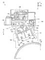
図29に示されるように、本実施形態に係る画像形成装置10は、上下方向(矢印V方向)の下側から上側へ向けて、記録媒体としてのシート部材Pが収容される収容部12と、収容部12の上に設けられ収容部12から供給されるシート部材Pに画像形成を行う画像形成部14と、画像形成部14の上に設けられ読取原稿Gを読み取る原稿読取部16と、画像形成部14内に設けられ画像形成装置10の各部の動作を制御する制御部20と、を含んで構成されている。
(overall structure)
As shown in FIG. 29, the image forming apparatus 10 according to the present embodiment includes an accommodating portion 12 that accommodates a sheet member P as a recording medium from the lower side to the upper side in the vertical direction (arrow V direction). An image forming unit 14 that forms an image on a sheet member P that is provided on the storage unit 12 and is supplied from the storage unit 12; a document reading unit 16 that is provided on the image forming unit 14 and reads a read document G; And a control unit 20 that is provided in the image forming unit 14 and controls the operation of each unit of the image forming apparatus 10.

なお、以後の説明では、画像形成装置10の装置本体10Aの上下方向(図29に示す矢印V方向)を単に上下方向と、水平方向(図29に示す矢印H方向)を単に水平方向と、奥行方向(図29に示す矢印D方向)を単に奥行方向と記載する。   In the following description, the vertical direction (the arrow V direction shown in FIG. 29) of the apparatus main body 10A of the image forming apparatus 10 is simply the vertical direction, and the horizontal direction (arrow H direction shown in FIG. 29) is simply the horizontal direction. The depth direction (arrow D direction shown in FIG. 29) is simply referred to as the depth direction.

収容部12には、サイズの異なるシート部材Pが収容される第1収容部22、第2収容部24、及び第3収容部26が設けられている。さらに、第1収容部22、第2収容部24、及び第3収容部26には、収容されたシート部材Pを画像形成装置10内に設けられた搬送路28に送り出す送り出しロール32が設けられている。   The storage unit 12 is provided with a first storage unit 22, a second storage unit 24, and a third storage unit 26 that store sheet members P having different sizes. Further, the first storage unit 22, the second storage unit 24, and the third storage unit 26 are provided with a delivery roll 32 that sends out the stored sheet member P to a conveyance path 28 provided in the image forming apparatus 10. ing.

そして、搬送路28において送り出しロール32に対してシート部材Pの搬送方向の下流側(以下単に搬送方向下流側と言う)には、シート部材Pを一枚ずつ搬送する搬送ロール34及び搬送ロール36がそれぞれ設けられている。また、搬送路28において搬送ロール36に対して搬送方向下流側には、シート部材Pを一端停止させるとともに、決められたタイミングでシート部材Pを後述する二次転写位置へ送り出す位置合せロール38が設けられている。   Then, on the downstream side in the conveyance direction of the sheet member P with respect to the delivery roll 32 in the conveyance path 28 (hereinafter simply referred to as the downstream side in the conveyance direction), the conveyance roll 34 and the conveyance roll 36 that convey the sheet member P one by one. Are provided. An alignment roll 38 that stops the sheet member P at one end and feeds the sheet member P to a secondary transfer position, which will be described later, at a predetermined timing on the downstream side in the conveyance direction with respect to the conveyance roll 36 in the conveyance path 28. Is provided.

さらに、画像形成部14の下側に設けられた搬送路28の下流側部分は、画像形成装置10の正面視において、画像形成部14の左側下部から画像形成部14の右側面に設けられた排紙部15まで設けられている。また、搬送路28には、シート部材Pの両面に画像形成を行うためにシート部材Pが搬送及び反転される両面搬送路29が接続されている。   Further, the downstream portion of the conveyance path 28 provided on the lower side of the image forming unit 14 is provided on the right side surface of the image forming unit 14 from the lower left side of the image forming unit 14 in the front view of the image forming apparatus 10. The paper discharge unit 15 is provided. The conveyance path 28 is connected to a double-side conveyance path 29 through which the sheet member P is conveyed and reversed in order to form an image on both sides of the sheet member P.

この両面搬送路29は、画像形成装置10の正面視において、搬送路28と両面搬送路29の切り替えが行われる第1切替部材31と、画像形成部14の右側下部から収容部12の右側まで上下方向に直線状に設けられた反転部33と、反転部33に搬送されたシート部材Pの後端が進入するとともに水平方向に搬送される搬送部37と、反転部33と搬送部37の切り替えが行われる第2切替部材35と、を有している。そして、反転部33には搬送ロール42が間隔をあけて複数箇所に設けられており、搬送部37には搬送ロール44が間隔をあけて複数箇所に設けられている。   The double-sided conveyance path 29 includes a first switching member 31 that switches between the conveyance path 28 and the double-sided conveyance path 29 from the lower right side of the image forming unit 14 to the right side of the storage unit 12 in the front view of the image forming apparatus 10. The reversing unit 33 provided in a straight line in the vertical direction, the rear end of the sheet member P conveyed to the reversing unit 33 enters and is conveyed in the horizontal direction, and the reversing unit 33 and the conveying unit 37 And a second switching member 35 that is switched. The reversing unit 33 is provided with a plurality of conveyance rollers 42 at intervals, and the conveyance unit 37 is provided with a plurality of conveyance rollers 44 at intervals.

この第1切替部材31は断面三角柱状の部材であり、図示しない駆動手段によって先端部が搬送路28又は両面搬送路29のいずれか一方に移動されることで、シート部材Pの搬送方向を切り替えるようになっている。同様に、第2切替部材35は断面三角柱状の部材であり、図示しない駆動手段によって先端部が反転部33又は搬送部37のいずれか一方に移動されることで、シート部材Pの搬送方向を切り替えるようになっている。   The first switching member 31 is a member having a triangular prism shape in cross section, and the conveyance direction of the sheet member P is switched by moving the leading end portion to either the conveyance path 28 or the double-sided conveyance path 29 by a driving unit (not shown). It is like that. Similarly, the second switching member 35 is a member having a triangular prism shape in cross section, and the conveyance direction of the sheet member P is changed by moving the leading end to either the reversing unit 33 or the conveyance unit 37 by a driving unit (not shown). It is supposed to switch.

なお、搬送部37における搬送方向下流側の端部は、搬送路28に図示しない案内部材により接続されている。また、画像形成部14の左側の壁面には、折り畳み式の手差給紙部46が設けられており、手差給紙部46から搬送路28の位置合せロール38の手前までが接続されている。   Note that the end of the transport unit 37 on the downstream side in the transport direction is connected to the transport path 28 by a guide member (not shown). Further, a foldable manual sheet feeding unit 46 is provided on the left wall surface of the image forming unit 14, and is connected from the manual sheet feeding unit 46 to a position in front of the alignment roll 38 in the conveyance path 28. Yes.

一方、画像形成装置10の上側に設けられた原稿読取部16には、読取原稿Gを1枚ずつ自動で搬送する原稿搬送装置52と、原稿搬送装置52の下側に配置され1枚の読取原稿Gが載せられるプラテンガラス54と、原稿搬送装置52によって搬送された読取原稿G又はプラテンガラス54に載せられた読取原稿Gを読み取る原稿読取装置56とが設けられている。   On the other hand, an original reading unit 16 provided on the upper side of the image forming apparatus 10 includes an original conveying device 52 that automatically conveys the read original G one by one, and a single reading that is disposed below the original conveying device 52. A platen glass 54 on which the document G is placed and a document reading device 56 that reads the read document G conveyed by the document conveying device 52 or the read document G placed on the platen glass 54 are provided.

この原稿搬送装置52は、搬送ロール53が複数配置された自動搬送路55を有しており、自動搬送路55の一部はシート部材Pがプラテンガラス54上を通るように配置されている。また、原稿読取装置56は、プラテンガラス54の左端部に静止した状態で原稿搬送装置52によって搬送された読取原稿Gを読み取り、又は水平方向に移動しながらプラテンガラス54に載せられた読取原稿Gを読み取るようになっている。   The document conveying device 52 has an automatic conveying path 55 in which a plurality of conveying rolls 53 are arranged, and a part of the automatic conveying path 55 is arranged so that the sheet member P passes over the platen glass 54. The document reading device 56 reads the read document G conveyed by the document conveying device 52 while being stationary at the left end of the platen glass 54, or reads the read document G placed on the platen glass 54 while moving in the horizontal direction. Is supposed to read.

さらに、原稿読取部16の下側に設けられた画像形成部14は、画像形成装置10の装置本体10Aの中央にトナー画像が表面に形成されて保持する円筒状の像保持体62が設けられている。像保持体62は、図示しない駆動手段によって矢印+R方向(図示の時計回り方向)に回転すると共に、光照射によって形成される静電潜像を保持するようになっている。また、像保持体62の上方で且つ像保持体62の表面と対向する位置には、像保持体62の表面を帯電するスコロトロン方式の帯電装置64が設けられている。なお、この帯電装置64については、詳細を後述する。   Further, the image forming unit 14 provided on the lower side of the document reading unit 16 is provided with a cylindrical image holding body 62 that forms and holds a toner image on the surface of the main body 10A of the image forming apparatus 10. ing. The image holding body 62 is rotated in the direction of the arrow + R (clockwise direction in the drawing) by a driving unit (not shown) and holds an electrostatic latent image formed by light irradiation. A scorotron charging device 64 that charges the surface of the image carrier 62 is provided above the image carrier 62 and at a position facing the surface of the image carrier 62. Details of the charging device 64 will be described later.

さらに、像保持体62の回転方向における帯電装置64よりも下流側でかつ像保持体62の表面と対向する位置には、露光装置66が設けられている。露光装置66は、LED(Light Emitting Diode)で構成されており、帯電装置64により帯電した像保持体62の表面に各トナー色に対応した画像信号に基づき、光を照射(露光)して静電潜像を形成するようになっている。なお、露光装置66はLED方式に限らず、例えば、レーザ光をポリゴンミラーで走査するものであってもよい。   Further, an exposure device 66 is provided at a position downstream of the charging device 64 in the rotation direction of the image carrier 62 and facing the surface of the image carrier 62. The exposure device 66 is configured by an LED (Light Emitting Diode), and the surface of the image holding body 62 charged by the charging device 64 is irradiated (exposed) with light based on image signals corresponding to each toner color, and is statically exposed. An electrostatic latent image is formed. The exposure device 66 is not limited to the LED system, and may be one that scans laser light with a polygon mirror, for example.

また、像保持体62の回転方向で露光装置66の露光光が照射される部位よりも下流側には、像保持体62の表面に形成された静電潜像を決められた色のトナーで現像して可視化させる回転切り替え式の現像装置70が設けられている。   Further, the electrostatic latent image formed on the surface of the image holding body 62 is formed with toner of a predetermined color on the downstream side of the portion irradiated with the exposure light of the exposure device 66 in the rotation direction of the image holding body 62. A rotation switching type developing device 70 for developing and visualizing is provided.

図28に示されるように、現像装置70は、イエロー(Y)、マゼンタ(M)、シアン(C)、黒(K)、第1特別色(E)、第2特別色(F)の各トナー色にそれぞれ対応する現像器72Y、72M、72C、72K、72E、72Fが、周方向に(反時計回り方向にこの順番で)並んで配置されている。そして、回転手段であるモータ(図示省略)によって中心角で60°ずつ回転することで、現像処理を行う現像器72Y、72M、72C、72K、72E、72Fが切り替えられ、像保持体62の表面と対向するようになっている。なお、現像器72Y、72M、72C、72K、72E、72Fは同様の構成となっているため、ここでは現像器72Yについて説明し、他の現像器72M、72C、72K、72E、72Fについては説明を省略する。   As shown in FIG. 28, the developing device 70 includes yellow (Y), magenta (M), cyan (C), black (K), first special color (E), and second special color (F). Developing units 72Y, 72M, 72C, 72K, 72E, and 72F corresponding to the toner colors are arranged side by side in the circumferential direction (counterclockwise in this order). Then, the developing devices 72Y, 72M, 72C, 72K, 72E, and 72F that perform the development processing are switched by rotating the central unit by 60 ° by a motor (not shown) that is a rotating means, and the surface of the image holding body 62 is switched. It comes to oppose. Since the developing units 72Y, 72M, 72C, 72K, 72E, and 72F have the same configuration, the developing unit 72Y will be described here, and the other developing units 72M, 72C, 72K, 72E, and 72F will be described. Is omitted.

現像器72Yは、本体となるケース部材76を有しており、ケース部材76内にトナーカートリッジ78Y(図29参照)からトナー供給路(図示省略)を経由して供給されるトナー及びキャリアから成る現像剤(図示省略)が充填されている。また、ケース部材76には、像保持体62の表面と対向して矩形状の開口部76Aが形成されており、開口部76Aには、表面が像保持体62の表面と対向する現像ロール74が設けられている。さらに、ケース部材76内で開口部76Aに近い部位には、現像剤の層厚を規制するための板状の規制部材79が、開口部76Aの長手方向に沿って設けられている。   The developing device 72Y includes a case member 76 serving as a main body, and includes toner and a carrier that are supplied into the case member 76 from a toner cartridge 78Y (see FIG. 29) via a toner supply path (not shown). A developer (not shown) is filled. Further, the case member 76 is formed with a rectangular opening 76 </ b> A facing the surface of the image holding body 62, and the developing roll 74 whose surface faces the surface of the image holding body 62 is formed in the opening 76 </ b> A. Is provided. Further, a plate-like regulating member 79 for regulating the layer thickness of the developer is provided along the longitudinal direction of the opening 76A at a portion near the opening 76A in the case member 76.

現像ロール74は、回転可能に設けられた円筒状の現像スリーブ74Aと、現像スリーブ74Aの内側に固定された複数の磁極から成る磁性部材74Bとで構成されており、現像スリーブ74Aが回転することで現像剤(キャリア)の磁気ブラシが形成されると共に、規制部材79で層厚が規制されることで、現像スリーブ74Aの表面に現像剤層を形成するようになっている。そして、現像スリーブ74Aの表面の現像剤層は、像保持体62に対向する位置に搬送され、像保持体62の表面に形成された潜像(静電潜像)に応じたトナーを付着させて現像を行う。   The developing roller 74 includes a cylindrical developing sleeve 74A that is rotatably provided, and a magnetic member 74B that includes a plurality of magnetic poles fixed inside the developing sleeve 74A. The developing sleeve 74A rotates. Thus, the developer (carrier) magnetic brush is formed, and the layer thickness is regulated by the regulating member 79, whereby the developer layer is formed on the surface of the developing sleeve 74A. The developer layer on the surface of the developing sleeve 74A is conveyed to a position facing the image carrier 62, and a toner corresponding to a latent image (electrostatic latent image) formed on the surface of the image carrier 62 is attached. To develop.

また、ケース部材76内には、螺旋状に形成された搬送オーガ77が2本回転可能に並列配置されており、この2本の搬送オーガ77が回転することで、ケース部材76内に充填された現像剤が、現像ロール74の軸方向(現像器72Yの長手方向)に循環搬送されるようになっている。なお、各現像器72Y、72M、72C、72K、72E、72Fに設けられた6本の現像ロール74は、隣の現像ロール74との間隔が中心角60°となるように周方向に配置されており、現像器72の切り替えにより、次の現像ロール74が像保持体62の表面と対向するようになっている。   Further, in the case member 76, two conveying augers 77 formed in a spiral shape are arranged in parallel so as to be rotatable, and the two conveying augers 77 are rotated to be filled in the case member 76. The developer is circulated and conveyed in the axial direction of the developing roll 74 (longitudinal direction of the developing device 72Y). The six developing rolls 74 provided in each of the developing units 72Y, 72M, 72C, 72K, 72E, and 72F are arranged in the circumferential direction so that the distance from the adjacent developing roll 74 is a central angle of 60 °. The next developing roller 74 is opposed to the surface of the image holding member 62 by switching the developing device 72.

さらに、像保持体62の回転方向で現像装置70よりも下流側であり、かつ像保持体62の下側には、像保持体62の表面に形成されたトナー画像が転写される中間転写ベルト68が設けられている。この中間転写ベルト68は、無端状であり、制御部20により回転駆動される駆動ロール61、中間転写ベルト68に張力を付与するための張力付与ロール63、中間転写ベルト68の裏面に接触して従動回転する複数の搬送ロール65、及び中間転写ベルト68の裏面に接触して従動回転する補助ロール69に巻き掛けられている。そして、中間転写ベルト68は、駆動ロール61が回転することにより、矢印−R方向(図示の反時計回り方向)に周回移動するようになっている。   Further, an intermediate transfer belt to which a toner image formed on the surface of the image carrier 62 is transferred is downstream of the developing device 70 in the rotation direction of the image carrier 62 and below the image carrier 62. 68 is provided. The intermediate transfer belt 68 is endless and is in contact with a drive roll 61 that is rotationally driven by the control unit 20, a tension applying roll 63 for applying tension to the intermediate transfer belt 68, and a back surface of the intermediate transfer belt 68. It is wound around a plurality of transport rolls 65 that are driven to rotate, and an auxiliary roll 69 that is driven to rotate in contact with the back surface of the intermediate transfer belt 68. The intermediate transfer belt 68 rotates in the direction of the arrow -R (the counterclockwise direction in the drawing) as the driving roll 61 rotates.

また、中間転写ベルト68を挟んで像保持体62の反対側には、像保持体62の表面に形成されたトナー画像を中間転写ベルト68に一次転写させる一次転写ロール67が設けられている。一次転写ロール67は、像保持体62と中間転写ベルト68とが接触する位置から中間転写ベルト68の移動方向下流側に離れた位置で、中間転写ベルト68の裏面に接触している。そして、一次転写ロール67は、図示しない電源から通電されることにより、接地されている像保持体62との電位差で像保持体62のトナー画像を中間転写ベルト68に一次転写するようになっている。   A primary transfer roll 67 is provided on the opposite side of the image carrier 62 across the intermediate transfer belt 68 to primarily transfer the toner image formed on the surface of the image carrier 62 to the intermediate transfer belt 68. The primary transfer roll 67 is in contact with the back surface of the intermediate transfer belt 68 at a position away from the position where the image carrier 62 and the intermediate transfer belt 68 are in contact with the downstream side in the moving direction of the intermediate transfer belt 68. When the primary transfer roll 67 is energized from a power source (not shown), the toner image on the image carrier 62 is primarily transferred to the intermediate transfer belt 68 by a potential difference from the grounded image carrier 62. Yes.

さらに、中間転写ベルト68を挟んで補助ロール69の反対側には、中間転写ベルト68上に一次転写されたトナー画像をシート部材Pに二次転写させる二次転写ロール71が設けられており、二次転写ロール71と補助ロール69との間がシート部材Pへトナー画像を転写する二次転写位置とされている。二次転写ロール71は、中間転写ベルト68の表面に接触している。そして、二次転写ロール71は接地されており、図示しない電源から軸にバイアス印加された補助ロール69と、接地された二次転写ロール71との電位差で、中間転写ベルト68のトナー画像をシート部材Pに二次転写するようになっている。   Further, on the opposite side of the auxiliary roll 69 across the intermediate transfer belt 68, a secondary transfer roll 71 for secondary transfer of the toner image primarily transferred onto the intermediate transfer belt 68 to the sheet member P is provided. A space between the secondary transfer roll 71 and the auxiliary roll 69 is a secondary transfer position for transferring the toner image to the sheet member P. The secondary transfer roll 71 is in contact with the surface of the intermediate transfer belt 68. The secondary transfer roll 71 is grounded, and the toner image of the intermediate transfer belt 68 is transferred to the sheet by a potential difference between the auxiliary roll 69 biased to the shaft from a power source (not shown) and the grounded secondary transfer roll 71. Secondary transfer is performed on the member P.

また、中間転写ベルト68を挟んで駆動ロール61の反対側には、中間転写ベルト68の二次転写後の残留トナーを掻き落とすブレード90Aを備えたクリーニング装置90が設けられている。   Further, on the opposite side of the drive roll 61 across the intermediate transfer belt 68, a cleaning device 90 provided with a blade 90A that scrapes off residual toner after secondary transfer of the intermediate transfer belt 68 is provided.

さらに、中間転写ベルト68の周囲で張力付与ロール63と対向する位置には、中間転写ベルト68の表面に付されたマーク(図示省略)を検知することで中間転写ベルト68上の予め定めた基準位置を検出し、画像形成処理の開始タイミングの基準となる位置検出信号を出力する位置検出センサ83が設けられている。   Further, a predetermined reference on the intermediate transfer belt 68 is detected by detecting a mark (not shown) on the surface of the intermediate transfer belt 68 at a position facing the tension applying roll 63 around the intermediate transfer belt 68. A position detection sensor 83 is provided for detecting a position and outputting a position detection signal that serves as a reference for the start timing of the image forming process.

また、像保持体62の回転方向で一次転写ロール67よりも下流側には、像保持体62の表面の帯電電位をマイナス側に帯電させて調整するコロトロン式の調整帯電器86が設けられている。さらに、像保持体62の回転方向で調整帯電器86よりも下流側には、中間転写ベルト68に一次転写されずに像保持体62の表面に残留した残留トナー等を清掃するクリーニング装置73が設けられている。   Further, a corotron type adjustment charger 86 is provided on the downstream side of the primary transfer roll 67 in the rotation direction of the image holding body 62 to adjust the charging potential on the surface of the image holding body 62 to the minus side. Yes. Further, a cleaning device 73 that cleans residual toner remaining on the surface of the image carrier 62 without being primarily transferred to the intermediate transfer belt 68 on the downstream side of the adjustment charger 86 in the rotation direction of the image carrier 62. Is provided.

また、像保持体62の回転方向でクリーニング装置73の下流側(帯電装置64よりも上流側)には、像保持体62の表面に光を照射して除電を行う除電装置75が設けられている。   Further, on the downstream side of the cleaning device 73 (upstream side of the charging device 64) in the rotation direction of the image holding body 62, there is provided a static elimination device 75 that performs static elimination by irradiating the surface of the image holding body 62 with light. Yes.

一方、図29に示されるように、二次転写ロール71によるトナー画像の二次転写位置は、前述の搬送路28の途中に設定されている。そして、搬送路28におけるシート部材Pの搬送方向(矢印Aで図示)で二次転写ロール71よりも下流側には、二次転写ロール71によってトナー画像が転写されたシート部材Pにトナー画像を定着させる定着装置80が設けられている。   On the other hand, as shown in FIG. 29, the secondary transfer position of the toner image by the secondary transfer roll 71 is set in the middle of the transport path 28 described above. Then, on the downstream side of the secondary transfer roll 71 in the conveyance direction (illustrated by an arrow A) of the sheet member P in the conveyance path 28, the toner image is transferred to the sheet member P on which the toner image is transferred by the secondary transfer roll 71. A fixing device 80 for fixing is provided.

定着装置80は、シート部材Pのトナー画像面側(上側)に配置され、通電により発熱する熱源を有する加熱ロール82と、加熱ロール82の下側に配置されシート部材Pを加熱ロール82の表面に向けて加圧する加圧ロール84とで構成されている。なお、搬送路28におけるシート部材Pの搬送方向で定着装置80よりも下流側には、排紙部15又は反転部33へ向けてシート部材Pを搬送する搬送ロール39が設けられている。   The fixing device 80 is disposed on the toner image surface side (upper side) of the sheet member P and has a heating roll 82 having a heat source that generates heat when energized, and the sheet member P disposed on the lower side of the heating roll 82 and the surface of the heating roll 82. It is comprised with the pressurization roll 84 which pressurizes toward. A transport roll 39 that transports the sheet member P toward the paper discharge unit 15 or the reversing unit 33 is provided downstream of the fixing device 80 in the transport direction of the sheet member P in the transport path 28.

一方、原稿読取装置56の下側で現像装置70よりも上側には、イエロー(Y)、マゼンタ(M)、シアン(C)、黒(K)、第1特別色(E)、第2特別色(F)の各トナーを収容するトナーカートリッジ78Y、78M、78C、78K、78E、78Fが水平方向に並んで交換可能に設けられている。   On the other hand, below the document reading device 56 and above the developing device 70, yellow (Y), magenta (M), cyan (C), black (K), first special color (E), and second special color. Toner cartridges 78Y, 78M, 78C, 78K, 78E, and 78F that store the respective color (F) toners are provided to be replaceable in the horizontal direction.

第1特別色E及び第2特別色Fは、イエロー、マゼンタ、シアン、ブラック以外の特別色(透明を含む)から選択され、または、選択されないようになっている。そして、現像装置70では、第1特別色E及び第2特別色Fが選択された場合はY、M、C、K、E、Fの6色での画像形成を行い、第1特別色E及び第2特別色Fが選択されない場合はY、M、C、Kの4色での画像形成を行うようになっている。なお、本実施形態では、一例として、Y、M、C、Kの4色で画像形成を行い、第1特別色E及び第2特別色Fを未使用とした場合について説明するが、他の例として、Y、M、C、Kの4色と第1特別色E又は第2特別色Fを用いて5色で画像形成を行ってもよい。   The first special color E and the second special color F are selected from special colors (including transparent) other than yellow, magenta, cyan, and black, or are not selected. Then, when the first special color E and the second special color F are selected, the developing device 70 forms an image with six colors of Y, M, C, K, E, and F, and the first special color E When the second special color F is not selected, image formation with four colors Y, M, C, and K is performed. In this embodiment, as an example, a case where image formation is performed with four colors Y, M, C, and K and the first special color E and the second special color F are unused will be described. As an example, image formation may be performed with five colors using four colors Y, M, C, and K and the first special color E or the second special color F.

以上の構成により、図29に示されるように、画像形成装置10を作動させると、画像処理装置(図示省略)又は外部から、イエロー(Y)、マゼンタ(M)、シアン(C)、黒(K)の各色の画像データが露光装置66に順次出力される。このとき、一例として、現像装置70は、現像器72Y(図28参照)が像保持体62の表面と対向するように回転し保持されている。また、クリーニング装置90のブレード90A及び二次転写ロール71は、各色のトナー画像が中間転写ベルト68に多重(一次)転写されるまで、中間転写ベルト68の表面から離されている。   With the above configuration, as shown in FIG. 29, when the image forming apparatus 10 is operated, yellow (Y), magenta (M), cyan (C), black (from the image processing apparatus (not shown) or from the outside. The image data of each color of K) is sequentially output to the exposure device 66. At this time, as an example, the developing device 70 is rotated and held so that the developing device 72Y (see FIG. 28) faces the surface of the image holding body 62. Further, the blade 90 </ b> A and the secondary transfer roll 71 of the cleaning device 90 are separated from the surface of the intermediate transfer belt 68 until the toner images of the respective colors are multiplexed (primary) transferred to the intermediate transfer belt 68.

続いて、露光装置66から画像データに応じて出射された光は、帯電装置64により帯電された像保持体62の表面を露光する。そして、例えば、像保持体62の表面にはイエローの画像データに対応した静電潜像が形成される。さらに、像保持体62の表面に形成された静電潜像は、現像器72Yによってイエローのトナー画像として現像される。そして、像保持体62の表面のイエローのトナー画像は、一次転写ロール67によって中間転写ベルト68に転写される。   Subsequently, the light emitted from the exposure device 66 according to the image data exposes the surface of the image carrier 62 charged by the charging device 64. For example, an electrostatic latent image corresponding to yellow image data is formed on the surface of the image carrier 62. Further, the electrostatic latent image formed on the surface of the image carrier 62 is developed as a yellow toner image by the developing device 72Y. Then, the yellow toner image on the surface of the image carrier 62 is transferred to the intermediate transfer belt 68 by the primary transfer roll 67.

続いて、現像装置70が矢印+R方向に60°回転され、現像器72Mが像保持体62の表面と対向する。そして、帯電、露光、現像の各工程が行われ、像保持体62の表面のマゼンタのトナー画像は、一次転写ロール67によって中間転写ベルト68のイエローのトナー画像上に転写される。同様にして、シアン(C)、黒(K)のトナー画像が中間転写ベルト68上に順次多重転写される。中間転写ベルト68に対してトナー画像の転写が終了すると、クリーニング装置90のブレード90A及び二次転写ロール71は、中間転写ベルト68の表面へ接する。   Subsequently, the developing device 70 is rotated by 60 ° in the direction of the arrow + R, and the developing device 72M faces the surface of the image carrier 62. Then, charging, exposure, and development steps are performed, and the magenta toner image on the surface of the image carrier 62 is transferred onto the yellow toner image on the intermediate transfer belt 68 by the primary transfer roll 67. Similarly, cyan (C) and black (K) toner images are sequentially transferred onto the intermediate transfer belt 68 in a multiple transfer manner. When the transfer of the toner image to the intermediate transfer belt 68 is completed, the blade 90A and the secondary transfer roll 71 of the cleaning device 90 are in contact with the surface of the intermediate transfer belt 68.

一方、収容部12から送り出され、搬送路28を搬送されてきたシート部材Pは、位置合せロール38により、中間転写ベルト68への各トナー画像の多重転写とタイミングを合わせて二次転写位置に搬送される。そして、中間転写ベルト68上に多重転写されたトナー画像は、二次転写位置に搬送されてきたシート部材P上に二次転写ロール71によって二次転写される。さらに、中間転写ベルト68の表面に付着した残留トナーがブレード90Aで中間転写ベルト68から掻き落とされて回収される。   On the other hand, the sheet member P sent out from the storage unit 12 and conveyed through the conveyance path 28 is moved to the secondary transfer position by the alignment roll 38 in synchronism with the multiple transfer of each toner image to the intermediate transfer belt 68. Be transported. The toner image that has been multiple-transferred onto the intermediate transfer belt 68 is secondarily transferred by the secondary transfer roll 71 onto the sheet member P that has been conveyed to the secondary transfer position. Further, residual toner adhering to the surface of the intermediate transfer belt 68 is scraped off from the intermediate transfer belt 68 by the blade 90A and collected.

続いて、トナー画像が転写されたシート部材Pは、定着装置80に向けて矢印A方向(図示の右方向)に搬送される。そして、定着装置80では、トナー画像が加熱ロール82及び加圧ロール84によって加熱、加圧されることでシート部材Pに定着される。さらに、トナー画像が定着されたシート部材Pは、一例として、排紙部15に排出される。なお、シート部材Pの両面に画像を形成する場合は、定着装置80で表面に画像定着を行った後、シート部材Pを矢印−V方向に沿って反転部33に送り込むと共に矢印+V方向に沿って送り出すことで、シート部材Pの先端と後端を入れ替える。そして、シート部材Pを両面搬送路29によって矢印B方向(図示の左方向)に搬送し、さらに搬送路28に送り込んで、シート部材Pの裏面の画像形成及び定着を表面と同様に行う。   Subsequently, the sheet member P to which the toner image has been transferred is conveyed toward the fixing device 80 in the direction of arrow A (right direction in the drawing). In the fixing device 80, the toner image is fixed on the sheet member P by being heated and pressed by the heating roll 82 and the pressure roll 84. Furthermore, the sheet member P on which the toner image is fixed is discharged to the paper discharge unit 15 as an example. When images are formed on both surfaces of the sheet member P, after the image is fixed on the surface by the fixing device 80, the sheet member P is sent to the reversing unit 33 along the arrow -V direction and along the arrow + V direction. The leading end and the trailing end of the sheet member P are exchanged. Then, the sheet member P is conveyed in the direction of arrow B (left direction in the figure) by the double-sided conveyance path 29 and further fed into the conveyance path 28 to perform image formation and fixing on the back surface of the sheet member P in the same manner as the front surface.

(要部構成)
次に、帯電装置64について説明する。
(Main part configuration)
Next, the charging device 64 will be described.

図8、図27に示されるように、帯電装置64は、像保持体62に対向して配置されると共に、像保持体62の回転軸方向(以下単に回転軸方向と言う。本実施例では奥行方向と同一方向)に延びる帯電器100と、この帯電器100を支持する装置本体102とを備えている。   As shown in FIGS. 8 and 27, the charging device 64 is disposed to face the image holding body 62 and is also referred to as a rotation axis direction of the image holding body 62 (hereinafter simply referred to as a rotation axis direction. In this embodiment). A charger 100 extending in the same direction as the depth direction) and an apparatus main body 102 that supports the charger 100 are provided.

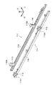
装置本体102には、帯電器100を装置本体102に対して回転軸方向に着脱自在に支持すると共に、帯電器100を支持した状態で像保持体62の表面に対して接離する接離方向(図8に示す矢印J方向、以下単に接離方向と言う)に移動可能な支持部材の一例としての一対のレール部材114が、帯電器100を水平方向から挟むように設けられている。   The apparatus main body 102 supports the charger 100 detachably with respect to the apparatus main body 102 in the direction of the rotation axis, and contacts and separates from the surface of the image carrier 62 while supporting the charger 100. A pair of rail members 114 as an example of a support member movable in the direction of arrow J shown in FIG. 8 (hereinafter simply referred to as the contact / separation direction) is provided so as to sandwich the charger 100 from the horizontal direction.

図8、図21、図22に示されるように、一対のレール部材114は、回転軸方向に延びるレール部116と、レール部116の両端側から上方向に延びる引掛部118とを備えている。そして、引掛部118の上端部には、帯電器100に対して外側に折り曲げられた板状の接触部118Aが設けられている。また、レール部116の長手方向に交差する断面は、互いに開放部が向かい合うようにコ字状とされている。さらに、図24に示されるように、レール部116の端部(奥行方向手前側の端部)は、装置本体102に備えられた支持板122に形成された開放口122Aを通して奥行方向手前側に開放されている。   As shown in FIGS. 8, 21, and 22, the pair of rail members 114 includes a rail portion 116 that extends in the rotation axis direction, and a hook portion 118 that extends upward from both ends of the rail portion 116. . A plate-like contact portion 118 </ b> A bent outward with respect to the charger 100 is provided at the upper end portion of the hook portion 118. Moreover, the cross section which cross | intersects the longitudinal direction of the rail part 116 is made into U shape so that an open part may face each other. Furthermore, as shown in FIG. 24, the end portion of the rail portion 116 (the end portion on the near side in the depth direction) is located on the near side in the depth direction through the opening 122 </ b> A formed in the support plate 122 provided in the apparatus main body 102. It is open.

そして、帯電器100には、この断面コ字状のレール部116に回転軸方向から挿入される当接部材の一例としての一対の板状のガイド部120が設けられており、このガイド部120をレール部116から回転軸方向に抜き差しすることで、後述する退避位置に配置された帯電器100が、開放口122Aを通って装置本体102から着脱されるようになっている(図25、図26参照)。   The charger 100 is provided with a pair of plate-shaped guide portions 120 as an example of an abutting member inserted into the rail portion 116 having a U-shaped cross section from the rotation axis direction. Is inserted into and removed from the rail portion 116 in the direction of the rotation axis, so that the charger 100 disposed at a retracted position, which will be described later, can be detached from the apparatus main body 102 through the opening 122A (FIGS. 25 and 25). 26).

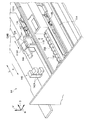
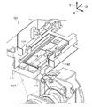
さらに、図5、図6に示されるように、装置本体102には、装置本体102に対して回転軸方向に移動可能に支持されると共に、レール部材114を支持する一対の移動部材124が回転軸方向に延びて設けられている。   Further, as shown in FIGS. 5 and 6, the apparatus main body 102 is supported by the apparatus main body 102 so as to be movable in the direction of the rotation axis, and a pair of moving members 124 supporting the rail member 114 are rotated. It extends in the axial direction.

詳細には、移動部材124は、帯電装置64を正面から見て右側に配置された移動部材124Aと左側に配置された移動部材124Bとから構成されている(以後の説明では移動部材124Aと移動部材124Bとを区別しない場合は、末尾のA、Bを省略する場合がある)。   Specifically, the moving member 124 includes a moving member 124A arranged on the right side and the moving member 124B arranged on the left side when the charging device 64 is viewed from the front (in the following description, the moving member 124A moves with the moving member 124A). If the member 124B is not distinguished, the last A and B may be omitted).

夫々の移動部材124の長手方向の両端側には、像保持体62からの距離が変化するように回転軸方向に対して傾斜した傾斜面部126が設けられ、この傾斜面部126に接するように前述したレール部材114の接触部118Aが支持されている。   On both end sides of each moving member 124 in the longitudinal direction, there are provided inclined surface portions 126 that are inclined with respect to the rotation axis direction so that the distance from the image holding body 62 changes. The contact portion 118A of the rail member 114 is supported.

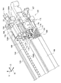
そして、図1、図2、図3、図4に示されるように、移動部材124を回転軸方向に移動させることにより、夫々の接触部118Aが夫々の傾斜面部126に沿って接離方向に移動するように力が伝達されるようになっている。   As shown in FIGS. 1, 2, 3, and 4, by moving the moving member 124 in the direction of the rotation axis, the respective contact portions 118 </ b> A are brought into contact / separation directions along the respective inclined surface portions 126. Force is transmitted to move.

接触部118Aが接離方向に移動することで、レール部材114にガイド部120によって支持されている帯電器100は、像保持体62の表面に接近して像保持体62の表面を帯電させる帯電位置と(図8参照)、像保持体62の表面から離間して退避する退避位置と(図7参照)に移動するようになっている。   When the contact portion 118A moves in the contact / separation direction, the charger 100 supported by the rail member 114 by the guide portion 120 approaches the surface of the image carrier 62 and charges the surface of the image carrier 62. It moves to a position (see FIG. 8) and a retreat position that retreats away from the surface of the image holding body 62 (see FIG. 7).

さらに、図1、図2に示されるように、装置本体102には、移動部材124を回転軸方向に移動させる駆動源の一例としてのステッピングモータ130が設けられ、ステッピングモータ130の回転軸130Aには、駆動ギア132が取り付けられている。一方、移動部材124Aの端部(奥行方向奥側の端部)には、回転軸方向に延びるラックギア134が形成されている。そして、駆動ギア132とラックギア134との間には、駆動ギア132の回転力をラックギア134に伝達するギア群136が設けられている。   Further, as shown in FIGS. 1 and 2, the apparatus main body 102 is provided with a stepping motor 130 as an example of a drive source for moving the moving member 124 in the direction of the rotation axis. The drive gear 132 is attached. On the other hand, a rack gear 134 extending in the rotation axis direction is formed at the end portion (end portion on the depth side in the depth direction) of the moving member 124A. A gear group 136 that transmits the rotational force of the drive gear 132 to the rack gear 134 is provided between the drive gear 132 and the rack gear 134.

さらに、一端部にラックギア134が形成された移動部材124Aと移動部材124Bとを連結させるブラケット140が、移動部材124Aと移動部材124Bとの間に掛け渡されるように設けられている。これより、移動部材124Aが回転軸方向に移動するのに追従して移動部材124Bも同様に回転軸方向に移動するようになっている。   Further, a bracket 140 for connecting the moving member 124A and the moving member 124B, each having a rack gear 134 formed at one end thereof, is provided so as to be spanned between the moving member 124A and the moving member 124B. Accordingly, following the movement of the moving member 124A in the direction of the rotation axis, the movement member 124B similarly moves in the direction of the rotation axis.

以上の構成により、制御部20(図29参照)の指示により、ステッピングモータ130が稼働すると、駆動ギア132及びギア群136を介してステッピングモータ130の駆動力がラックギア134を備える移動部材124Aに伝達される。ステッピングモータ130の駆動力が伝達された移動部材124A及びブラケット140を介して移動部材124Aと連結された移動部材124Bは回転軸方向に移動する。移動部材124が回転軸方向に移動すると、夫々の接触部118Aが夫々の傾斜面部126に沿って接離方向に移動する。接触部118Aが接離方向に移動することで、レール部材114及びレール部材114に支持されるガイド部120が接離方向に移動する。これにより、帯電器100は、像保持体62の表面に接近して像保持体の表面を帯電させる帯電位置と(図8参照)、像保持体62の表面から離間して退避させる退避位置と(図7参照)に移動するようになっている。   With the above configuration, when the stepping motor 130 is operated according to an instruction from the control unit 20 (see FIG. 29), the driving force of the stepping motor 130 is transmitted to the moving member 124A including the rack gear 134 via the driving gear 132 and the gear group 136. Is done. The moving member 124A to which the driving force of the stepping motor 130 is transmitted and the moving member 124B connected to the moving member 124A via the bracket 140 move in the rotation axis direction. When the moving member 124 moves in the rotation axis direction, the respective contact portions 118A move in the contact / separation direction along the respective inclined surface portions 126. When the contact portion 118A moves in the contact / separation direction, the rail member 114 and the guide portion 120 supported by the rail member 114 move in the contact / separation direction. As a result, the charger 100 approaches the surface of the image carrier 62 and charges the surface of the image carrier (see FIG. 8), and the retreat position retracts away from the surface of the image carrier 62. (See FIG. 7).

以上より、帯電器100を帯電位置と退避位置とに接離させる接離手段128は、ステッピングモータ130、ギア群136、ラックギア134、移動部材124及びレール部材114等とを含んで構成されている。   As described above, the contact / separation means 128 that contacts and separates the charger 100 between the charging position and the retracted position includes the stepping motor 130, the gear group 136, the rack gear 134, the moving member 124, the rail member 114, and the like. .

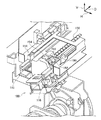
一方、図3、図4に示されるように、移動部材124Bの端部(奥行方向手前側の端部)には、回転軸方向に延びる板状の検出板144が設けられている。さらに、この検出板144を検出する検出手段の一例としてのセンサ142が設けられている。   On the other hand, as shown in FIGS. 3 and 4, a plate-like detection plate 144 extending in the rotation axis direction is provided at the end of the moving member 124 </ b> B (the end on the near side in the depth direction). Further, a sensor 142 is provided as an example of detection means for detecting the detection plate 144.

詳細には、センサ142には、上下方向に離間した一対の検知部142Aが設けられ、この一対の検知部142Aの間に、検出板144が挿入されると、センサ142が検出板144を検知するようになっている。これにより、帯電器100を帯電位置(図8参照)に移動させるように移動部材124Bが回転軸方向に移動するとセンサ142が検出板144を検知する(図4参照)。一方、帯電器100を退避位置(図7参照)に移動させるように移動部材124Bが回転軸方向に移動するとセンサ142が検出板144を検知しないようになっている(図3参照)。   Specifically, the sensor 142 is provided with a pair of detection units 142A that are spaced apart in the vertical direction. When the detection plate 144 is inserted between the pair of detection units 142A, the sensor 142 detects the detection plate 144. It is supposed to be. Accordingly, when the moving member 124B moves in the direction of the rotation axis so as to move the charger 100 to the charging position (see FIG. 8), the sensor 142 detects the detection plate 144 (see FIG. 4). On the other hand, when the moving member 124B moves in the direction of the rotation axis so as to move the charger 100 to the retracted position (see FIG. 7), the sensor 142 does not detect the detection plate 144 (see FIG. 3).

また、図1、図2、図3、図4、図5、図6に示されるように、レール部116の長手方向の両端側には、付勢部材の一例としてのねじりコイルバネ148が設けられ、レール部116に挿入されたガイド部120の下面をレール部116に押し付けるように付勢するようになっている。   Further, as shown in FIGS. 1, 2, 3, 4, 5, and 6, torsion coil springs 148 as an example of an urging member are provided on both ends in the longitudinal direction of the rail portion 116. The lower surface of the guide part 120 inserted into the rail part 116 is urged so as to press against the rail part 116.

次に、装置本体102に着脱可能に保持される帯電器100について説明する。   Next, the charger 100 that is detachably held in the apparatus main body 102 will be described.

図10、図23に示されるように、帯電器100は、回転軸方向に延びて設けられ、像保持体62(図8参照)側が開放された筐体106を備えている。そして、この筐体106の外表面から突出するように、前述した板状のガイド部120が回転軸方向に延びるように設けられている。   As shown in FIGS. 10 and 23, the charger 100 is provided with a casing 106 that extends in the direction of the rotation axis and is open on the image carrier 62 (see FIG. 8) side. And the plate-shaped guide part 120 mentioned above is provided so that it may protrude from the outer surface of this housing | casing 106 in a rotating shaft direction.

さらに、図9、図10に示されるように、筐体106の像保持体62側を向いた開口部の四隅側で、後述するワイヤ支持部材192及びワイヤ支持部材194には、像保持体62に向けて突出する突出部107が形成されている。   Further, as shown in FIGS. 9 and 10, on the four corner sides of the opening of the housing 106 facing the image holding body 62, the image supporting body 62 is disposed on the wire supporting member 192 and the wire supporting member 194 described later. A projecting portion 107 projecting toward the surface is formed.

一方、図11に示されるように、像保持体62の回転軸方向の両側には、像保持体62を回転軸方向の両側から支持すると共に図示せぬフレーム部材に固定される支持部材149とを備えている。   On the other hand, as shown in FIG. 11, on both sides of the image holding body 62 in the rotation axis direction, a support member 149 that supports the image holding body 62 from both sides in the rotation axis direction and is fixed to a frame member (not shown). It has.

さらに、支持部材149には、帯電位置に配置された帯電器100の突出部107が押し付けられる位置基準部150が設けられている。   Further, the support member 149 is provided with a position reference portion 150 against which the protruding portion 107 of the charger 100 disposed at the charging position is pressed.

そして、図8に示されるように、帯電器100が帯電位置に配置された状態では、前述したねじりコイルバネ148の付勢力により夫々の突出部107が支持部材149に設けられた位置基準部150に押し付けられるようになっており、この状態では、ガイド部120の下面が、レール部116から離間するようになっている。   As shown in FIG. 8, in a state where the charger 100 is disposed at the charging position, the respective protruding portions 107 are formed on the position reference portion 150 provided on the support member 149 by the biasing force of the torsion coil spring 148 described above. In this state, the lower surface of the guide portion 120 is separated from the rail portion 116.

つまり、帯電器100が帯電位置に配置されて、ねじりコイルバネ148の付勢力により突出部107が位置基準部150に押し付けられた状態では、ガイド部120とレール部116とが接離方向に離間するように、突出部107、ガイド部120及びレール部116の形状が決められている。   That is, when the charger 100 is disposed at the charging position and the protruding portion 107 is pressed against the position reference portion 150 by the urging force of the torsion coil spring 148, the guide portion 120 and the rail portion 116 are separated in the contact / separation direction. Thus, the shape of the protrusion part 107, the guide part 120, and the rail part 116 is determined.

すなわち、ねじりコイルバネ148の付勢力により突出部107が位置基準部150に押し付けられるのをレール部116にじゃまされないようになっている。   That is, the rail portion 116 does not interfere with the protrusion 107 being pressed against the position reference portion 150 by the biasing force of the torsion coil spring 148.

さらに、図8に示されるように、帯電器100は、前述した筐体106と、筐体106の内側に配置され、回転軸方向に延びる放電電極の一例としての2本の放電ワイヤ104と、筐体106の像保持体62側に向いた開口を覆うように設けられ、像保持体62の外表面に沿って湾曲状とされたメッシュ状金属板のグリッド108とを含んで構成されている。   Further, as shown in FIG. 8, the charger 100 includes the above-described casing 106, two discharge wires 104 as an example of discharge electrodes that are disposed inside the casing 106 and extend in the rotation axis direction, A mesh-shaped metal plate grid 108 is provided so as to cover the opening facing the image holding body 62 side of the housing 106, and is curved along the outer surface of the image holding body 62. .

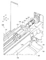
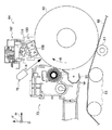
また、図14に示されるように、筐体106の内部には、回転軸方向に延びると共に、帯電器100の外部に設けられた駆動源(図示省略)の駆動力が伝達されて周方向に回転する円柱状の円柱部材の一例としてのリードシャフト156と、リードシャフト156の回転力が伝達されて回転軸方向に往復移動する往復移動部材158と、往復移動部材158に対して接離方向に相対移動可能に支持されると共に、往復移動部材158の回転軸方向の移動力が伝達されて回転軸方向に移動して放電ワイヤ104及びグリッド108を清掃する清掃部材160が設けられている。   Further, as shown in FIG. 14, the casing 106 extends in the direction of the rotation axis, and the driving force of a driving source (not shown) provided outside the charger 100 is transmitted in the circumferential direction. A lead shaft 156 as an example of a rotating columnar column member, a reciprocating member 158 that reciprocates in the direction of the rotation axis when the rotational force of the lead shaft 156 is transmitted, and a contact / separation direction with respect to the reciprocating member 158 A cleaning member 160 is provided that is supported so as to be relatively movable, and that moves in the direction of the rotational axis of the reciprocating member 158 and moves in the direction of the rotational axis to clean the discharge wire 104 and the grid 108.

詳細には、図18に示されるように、装置本体102には、帯電器100の外部に設けられた駆動源(図示省略)の駆動力が伝達されて回転する凹状の凹部の一例としての係合凹部162が設けられている。そして、係合凹部162の壁面には、回転軸方向に延びる複数個の溝部162Aが形成されており、リードシャフト156の端部(奥行方向奥側の端部)には、この溝部162Aに嵌って駆動力が伝達される伝達部164が設けられている(図14参照)。これより、図19、図20に示されるように、回転軸方向に着脱される帯電器100のリードシャフト156に設けられた伝達部164は、係合凹部162に対して回転軸方向に着脱自在とされる。   Specifically, as shown in FIG. 18, the apparatus main body 102 is an example of a concave concave portion that rotates by being transmitted with a driving force of a driving source (not shown) provided outside the charger 100. A concavity 162 is provided. A plurality of grooves 162A extending in the rotation axis direction are formed on the wall surface of the engaging recess 162, and the end of the lead shaft 156 (the end on the back side in the depth direction) is fitted into the groove 162A. Thus, a transmission portion 164 to which the driving force is transmitted is provided (see FIG. 14). Accordingly, as shown in FIGS. 19 and 20, the transmission portion 164 provided on the lead shaft 156 of the charger 100 detachable in the rotation axis direction is detachable in the rotation axis direction with respect to the engagement recess 162. It is said.

さらに、図14に示されるように、周方向に回転するリードシャフト156の外周面には、螺旋状の螺旋突起156Aが設けられており、この螺旋突起156Aと噛み合う溝部(図示省略)が、往復移動部材158に設けられた円筒部158Aの内周面に形成されている。これにより、リードシャフト156を一方及び他方に回転させることで往復移動部材158がリードシャフト156に沿って回転軸方向に往復移動するようになっている。   Further, as shown in FIG. 14, a spiral spiral protrusion 156A is provided on the outer peripheral surface of the lead shaft 156 that rotates in the circumferential direction, and a groove (not shown) that meshes with the spiral protrusion 156A reciprocates. It is formed on the inner peripheral surface of a cylindrical portion 158 </ b> A provided on the moving member 158. Accordingly, the reciprocating member 158 is reciprocated along the lead shaft 156 in the rotation axis direction by rotating the lead shaft 156 in one direction and the other.

また、放電ワイヤ104及びグリッド108を清掃する清掃部材160は、往復移動部材158に対して接離方向に相対移動可能に支持されると共に、往復移動部材158の回転軸方向の移動力が伝達される接続部168と、接続部168の端部に接続されると共に放電ワイヤ104を囲む本体部170と、本体部170の水平方向両端部と接続されると共にグリッド108の表面側(像保持体62を向いた側)及び裏面側と当ってグリッド108を清掃するグリッド清掃部172とを備えている。   The cleaning member 160 that cleans the discharge wire 104 and the grid 108 is supported so as to be relatively movable in the contact / separation direction with respect to the reciprocating member 158, and the moving force in the rotation axis direction of the reciprocating member 158 is transmitted. Connected to the end of the connecting portion 168 and surrounding the discharge wire 104, and connected to both ends in the horizontal direction of the main portion 170 and on the surface side of the grid 108 (the image carrier 62). And a grid cleaning part 172 that cleans the grid 108 against the back surface side.

そして、接続部168は、筐体106の接離方向の移動に伴って装置本体102に対して接離方向に移動すると共に、筐体106に対して回転軸方向に移動可能となるように筐体106に支持されている。   The connection unit 168 moves in the contact / separation direction with respect to the apparatus main body 102 as the housing 106 moves in the contact / separation direction, and moves in the rotation axis direction with respect to the housing 106. It is supported by the body 106.

また、図12、図17に示されるように、リードシャフト156の両端部を回転可能に支持する支持部材188及び支持部材190が設けられている。そして、この支持部材188及び支持部材190には、放電ワイヤ104の端部を支持するワイヤ支持部材192及びワイヤ支持部材194がカイド部188Aに挟まれて接離方向に移動可能に設けられている。また、このワイヤ支持部材192及びワイヤ支持部材194は、筐体106に固定されており、筐体106の接離方向の移動に伴なって接離方向に移動するようになっている。   Also, as shown in FIGS. 12 and 17, a support member 188 and a support member 190 that rotatably support both ends of the lead shaft 156 are provided. The support member 188 and the support member 190 are provided with a wire support member 192 and a wire support member 194 that support the end portion of the discharge wire 104 so as to be movable in the contact / separation direction between the guide portions 188A. . Further, the wire support member 192 and the wire support member 194 are fixed to the housing 106, and move in the contact / separation direction as the housing 106 moves in the contact / separation direction.

以上の構成により、筐体106が接離方向に移動すると、支持部材188、支持部材190及びリードシャフト156が移動することなく、ワイヤ支持部材192、ワイヤ支持部材194、放電ワイヤ104及び清掃部材160が装置本体102に対して接離方向に移動するようになっている。   With the above configuration, when the housing 106 moves in the contact / separation direction, the support member 188, the support member 190, and the lead shaft 156 do not move, and the wire support member 192, the wire support member 194, the discharge wire 104, and the cleaning member 160 are moved. Is moved in the contact / separation direction with respect to the apparatus main body 102.

一方、図12、図14に示されるように、本体部170の内部には、放電ワイヤ104の下側から当り、放電ワイヤ104を清掃する清掃パッド174が設けられている。   On the other hand, as shown in FIGS. 12 and 14, a cleaning pad 174 that hits from below the discharge wire 104 and cleans the discharge wire 104 is provided inside the main body 170.

さらに、本体部170の内部には、清掃部材160が回転軸方向に移動して放電ワイヤ104を清掃する清掃時には、放電ワイヤ104の上側から当り放電ワイヤ104を清掃する清掃パッド176が設けられている。   Further, a cleaning pad 176 for cleaning the discharge wire 104 from the upper side of the discharge wire 104 is provided inside the main body 170 when the cleaning member 160 moves in the rotation axis direction to clean the discharge wire 104. Yes.

詳細には、図15に示されるように、清掃パッド176は、回転軸方向に延びると共に一端部を中心に回転移動する支持部材178の他端部に取り付けられている。そして、図12、図15(A)に示されるように、清掃部材160が、帯電器100の端部に待機した状態では、清掃パッド176は、放電ワイヤ104と離間するようになっている。   Specifically, as shown in FIG. 15, the cleaning pad 176 is attached to the other end portion of the support member 178 that extends in the rotation axis direction and rotates around the one end portion. 12 and 15A, the cleaning pad 176 is separated from the discharge wire 104 in a state where the cleaning member 160 stands by at the end of the charger 100. As shown in FIG.

一方、図13に示されるように、退避位置に配置された帯電器100の端部に待機していた清掃部材160を回転軸方向に移動させて清掃開始位置(図13参照)に移動させると、図15(B)に示されるように、支持部材178が回転移動して清掃パッド176が放電ワイヤ104の上面に当るようになっている。   On the other hand, as shown in FIG. 13, when the cleaning member 160 waiting at the end of the charger 100 arranged at the retracted position is moved in the direction of the rotation axis and moved to the cleaning start position (see FIG. 13). As shown in FIG. 15B, the support member 178 rotates and the cleaning pad 176 comes into contact with the upper surface of the discharge wire 104.

そして、この状態で、清掃部材160が放電ワイヤ104及びグリッド108に沿って回転軸方向に往復移動することで、放電ワイヤ104及びグリッド108が清掃されるようになっている。つまり、帯電器100が退避位置に配置されることで、グリッド108と像保持体62との間にグリッド清掃部172が通る隙間が生じることで、グリッド108が清掃されるようになっている。   In this state, the cleaning member 160 reciprocates in the direction of the rotation axis along the discharge wire 104 and the grid 108, whereby the discharge wire 104 and the grid 108 are cleaned. That is, when the charger 100 is disposed at the retracted position, a gap through which the grid cleaning unit 172 passes between the grid 108 and the image holding body 62 is generated, so that the grid 108 is cleaned.

さらに、図18に示されるように、装置本体102における係合凹部162の近傍(帯電器100が装置本体102に装着された状態で帯電器100の回転軸方向一端側)には、回転軸方向に突出する突出部材の一例としての位置決めピン180が設けられている。また、図16に示されるように、装置本体102における開放口122Aの近傍(帯電器100が装置本体102に装着された状態で帯電器100の回転軸方向他端側)には、回転軸方向に突出する突出部材の一例としての位置決めピン182が設けられている。   Further, as shown in FIG. 18, in the vicinity of the engagement recess 162 in the apparatus main body 102 (on the one end side in the rotation axis direction of the charger 100 when the charger 100 is mounted on the apparatus main body 102), the rotation axis direction A positioning pin 180 is provided as an example of a protruding member that protrudes toward the center. Further, as shown in FIG. 16, in the vicinity of the opening 122 </ b> A in the apparatus main body 102 (in the state where the charger 100 is attached to the apparatus main body 102, the other end side in the rotation axis direction of the charger 100) A positioning pin 182 is provided as an example of a protruding member that protrudes from the center.

これに対し、図12に示されるように、帯電器100が装置本体102に装着された状態で、装置本体102に設けられた位置決めピン180(図18参照)が嵌る嵌合部の一例としての位置決め孔184が、支持部材188に形成されている。また、図17に示されるように、帯電器100が装置本体102に装着された状態で、装置本体102に設けられた位置決めピン182(図16参照)が嵌る嵌合部の一例としての位置決め孔186が、支持部材190に形成されている。   On the other hand, as shown in FIG. 12, as an example of a fitting portion into which a positioning pin 180 (see FIG. 18) provided in the apparatus main body 102 fits in a state where the charger 100 is attached to the apparatus main body 102. A positioning hole 184 is formed in the support member 188. Further, as shown in FIG. 17, a positioning hole as an example of a fitting portion into which a positioning pin 182 (see FIG. 16) provided on the apparatus main body 102 fits in a state where the charger 100 is mounted on the apparatus main body 102. 186 is formed on the support member 190.

この構成により、帯電器100を装置本体102に装着する際には、帯電器100のガイド部120を装置本体102に設けられたレール部116(図7参照)に挿入し、帯電器100に設けられた位置決め孔184及び位置決め孔186を、装置本体102に設けられた位置決めピン180及び位置決めピン182へ差し込むことで、リードシャフト156の端部に設けられた伝達部164が、係合凹部162の溝部162Aに嵌るようになっている(図19参照)。   With this configuration, when the charger 100 is mounted on the apparatus main body 102, the guide portion 120 of the charger 100 is inserted into the rail portion 116 (see FIG. 7) provided on the apparatus main body 102, and is provided on the charger 100. By inserting the positioning hole 184 and the positioning hole 186 into the positioning pin 180 and the positioning pin 182 provided in the apparatus main body 102, the transmission part 164 provided at the end of the lead shaft 156 is connected to the engaging recess 162. It fits into the groove 162A (see FIG. 19).

(要部構成の作用)
次に、帯電装置64の作用について説明する。
(Effects of main components)
Next, the operation of the charging device 64 will be described.

図26に示されるように、帯電器100を装置本体102にから離脱させる場合には、帯電位置から退避位置に移動させた帯電器100(図7参照)を回転軸方向に移動させることで、装置本体102から帯電器100を離脱させる。   As shown in FIG. 26, when the charger 100 is detached from the apparatus main body 102, the charger 100 (see FIG. 7) moved from the charging position to the retracted position is moved in the rotation axis direction. The charger 100 is detached from the apparatus main body 102.

具体的には、帯電器100に設けられたガイド部120を、装置本体102に設けられたレール部116(図7参照)に沿って回転軸方向に抜き出すことで帯電器100が装置本体102から離脱される。   Specifically, the charger 100 is removed from the apparatus main body 102 by extracting the guide section 120 provided in the charger 100 along the rail section 116 (see FIG. 7) provided in the apparatus main body 102 in the rotation axis direction. Will be withdrawn.

さらに、帯電器100を装置本体102に装着させる場合には、帯電器100のガイド部120を装置本体102に設けられたレール部116(図7参照)に挿入する。そして、図12、図17に示されるように、帯電器100に設けられた位置決め孔184及び位置決め孔186を、装置本体102に設けられた位置決めピン180(図18参照)及び位置決めピン182(図16参照)へ差し込む。これにより、図19に示されるように、リードシャフト156の端部に設けられた伝達部164が、係合凹部162の溝部162Aに嵌り、帯電器100が、退避位置に配置される(図7参照)。   Further, when the charger 100 is attached to the apparatus main body 102, the guide portion 120 of the charger 100 is inserted into a rail portion 116 (see FIG. 7) provided in the apparatus main body 102. 12 and 17, the positioning hole 184 and the positioning hole 186 provided in the charger 100 are replaced with the positioning pin 180 (see FIG. 18) and the positioning pin 182 (see FIG. 18) provided in the apparatus main body 102, respectively. 16). As a result, as shown in FIG. 19, the transmission portion 164 provided at the end of the lead shaft 156 fits into the groove portion 162A of the engagement recess 162, and the charger 100 is disposed at the retracted position (FIG. 7). reference).

図1に示されるように、帯電器100を退避位置から帯電位置に移動させる場合には、制御部20(図29参照)の指示により、ステッピングモータ130を駆動させ、駆動ギア132及びギア群136を介してステッピングモータ130の駆動力を、ラックギア134を備える移動部材124Aに伝達させる。   As shown in FIG. 1, when the charger 100 is moved from the retracted position to the charging position, the stepping motor 130 is driven by the instruction of the control unit 20 (see FIG. 29), and the drive gear 132 and the gear group 136 are driven. Then, the driving force of the stepping motor 130 is transmitted to the moving member 124A including the rack gear 134.

図1、図2、図3、図4に示されるように、ステッピングモータ130の駆動力が伝達された移動部材124は、回転軸方向に移動する(矢印Kに移動する)。移動部材124が回転軸方向(矢印K方向)に移動すると、移動部材124に形成された夫々の傾斜面部126も回転軸方向(矢印K方向)に移動する。傾斜面部126が回転軸方向(矢印K方向)に移動することで、傾斜面部126に接するように配置されたレール部材114の接触部118Aが傾斜面部126に沿って移動し、レール部材114が像保持体62(図7参照)に近づくように接離方向に移動する。ここで、図7に示されるように、帯電器100が退避位置に配置される場合には、ねじりコイルバネ148の付勢力でレール部116に挿入された帯電器100のガイド部120の下面はレール部116に押し付けられている。   As shown in FIGS. 1, 2, 3, and 4, the moving member 124, to which the driving force of the stepping motor 130 is transmitted, moves in the direction of the rotation axis (moves in the arrow K). When the moving member 124 moves in the rotation axis direction (arrow K direction), each inclined surface portion 126 formed on the moving member 124 also moves in the rotation axis direction (arrow K direction). As the inclined surface portion 126 moves in the rotation axis direction (arrow K direction), the contact portion 118A of the rail member 114 arranged to contact the inclined surface portion 126 moves along the inclined surface portion 126, and the rail member 114 is imaged. It moves in the contact / separation direction so as to approach the holding body 62 (see FIG. 7). Here, as shown in FIG. 7, when the charger 100 is disposed at the retracted position, the lower surface of the guide portion 120 of the charger 100 inserted into the rail portion 116 by the urging force of the torsion coil spring 148 is the rail. It is pressed against the part 116.

そして、図8に示されるように、レール部材114が接離方向に移動して、帯電器100が帯電位置に移動すると、制御部20(図29参照)の指示により、ステッピングモータ130の駆動力が停止する。駆動力の停止に関しては、図4に示されるように、帯電器100が帯電位置に配置されるように移動部材124Bが回転軸方向に移動すると、移動部材124Bに設けられた検出板144が、センサ142に設けられた一対の検知部142Aの間に挿入し、帯電器100が帯電位置に移動したのが検知されることによって制御部20からの指示によって実施される。   Then, as shown in FIG. 8, when the rail member 114 moves in the contact / separation direction and the charger 100 moves to the charging position, the driving force of the stepping motor 130 is instructed by the control unit 20 (see FIG. 29). Stops. Regarding the stop of the driving force, as shown in FIG. 4, when the moving member 124B moves in the direction of the rotation axis so that the charger 100 is disposed at the charging position, the detection plate 144 provided on the moving member 124B It is inserted between a pair of detection units 142A provided in the sensor 142, and is executed according to an instruction from the control unit 20 by detecting that the charger 100 has moved to the charging position.

なお、清掃部材160の接続部168が、リードシャフト156に支持された往復移動部材158に対して接離方向に相対移動可能に支持されるため、リードシャフト156及び往復移動部材158は、接離方向には移動せず、帯電器100に設けられた他の部材が接離方向に移動する。   Since the connecting portion 168 of the cleaning member 160 is supported so as to be movable relative to the reciprocating member 158 supported by the lead shaft 156 in the contact / separation direction, the lead shaft 156 and the reciprocating member 158 are contacted / separated. The other members provided in the charger 100 move in the contact / separation direction without moving in the direction.

また、図8、図11に示されるように、帯電器100が帯電位置に移動すると、帯電器100に設けられた突出部107が、ねじりコイルバネ148の付勢力で像保持体62に設けられた位置基準部150に押し付けられる。突出部107が位置基準部150に押し付けられる状態では、ガイド部120の下面が、レール部116から離間している。   Further, as shown in FIGS. 8 and 11, when the charger 100 is moved to the charging position, the protrusion 107 provided on the charger 100 is provided on the image carrier 62 by the biasing force of the torsion coil spring 148. It is pressed against the position reference unit 150. In a state where the protruding portion 107 is pressed against the position reference portion 150, the lower surface of the guide portion 120 is separated from the rail portion 116.

一方、図2、図4に示されるように、帯電器100を帯電位置から退避位置に移動させる場合には、制御部20(図29参照)の指示により駆動するステッピングモータ130の駆動力が、駆動ギア132及びギア群136を介して移動部材124に伝達され、移動部材124は回転軸方向に移動する(矢印Lに移動する)。   On the other hand, as shown in FIGS. 2 and 4, when the charger 100 is moved from the charging position to the retracted position, the driving force of the stepping motor 130 driven by the instruction of the control unit 20 (see FIG. 29) is It is transmitted to the moving member 124 via the drive gear 132 and the gear group 136, and the moving member 124 moves in the direction of the rotation axis (moves in the arrow L).

図1、図3に示されるように、移動部材124が回転軸方向(矢印L方向)に移動すると、移動部材124に形成された夫々の傾斜面部126も回転軸方向(矢印L方向)に移動する。傾斜面部126が回転軸方向(矢印L方向)に移動することで、傾斜面部126に接するように配置されたレール部材114の接触部118Aが傾斜面部126に沿って像保持体62(図7参照)から離れるように接離方向に移動する。   As shown in FIGS. 1 and 3, when the moving member 124 moves in the rotation axis direction (arrow L direction), each inclined surface portion 126 formed on the moving member 124 also moves in the rotation axis direction (arrow L direction). To do. As the inclined surface portion 126 moves in the rotation axis direction (arrow L direction), the contact portion 118A of the rail member 114 arranged so as to contact the inclined surface portion 126 is moved along the inclined surface portion 126 (see FIG. 7). ) Move away from and away from).

図7に示されるように、帯電器100が像保持体62から離れるように移動すると、帯電器100に設けられた突出部107が、像保持体62に設けられた位置基準部150から離れる。そして、ねじりコイルバネ148の付勢力で、レール部116に挿入された帯電器100のガイド部120の下面がレール部116に押し付けられる。   As shown in FIG. 7, when the charger 100 moves away from the image carrier 62, the protrusion 107 provided on the charger 100 moves away from the position reference unit 150 provided on the image carrier 62. The lower surface of the guide portion 120 of the charger 100 inserted into the rail portion 116 is pressed against the rail portion 116 by the urging force of the torsion coil spring 148.

レール部材114が接離方向に移動して、帯電器100が退避位置に移動すると、制御部20(図29参照)の指示により、ステッピングモータ130が停止する。駆動力の停止に関しては、図3に示されるように、帯電器100が退避位置に配置されるように移動部材124Bが回転軸方向に移動すると、移動部材124Bに設けられた検出板144が、センサ142に設けられた一対の検知部142Aの間から抜き去られ、帯電器100が退避位置に移動したのが検知されることによって制御部20からの指示によって実施される。   When the rail member 114 moves in the contact / separation direction and the charger 100 moves to the retracted position, the stepping motor 130 is stopped by an instruction from the control unit 20 (see FIG. 29). For stopping the driving force, as shown in FIG. 3, when the moving member 124B moves in the direction of the rotation axis so that the charger 100 is disposed at the retracted position, the detection plate 144 provided on the moving member 124B This is performed according to an instruction from the control unit 20 by detecting that the charger 100 is removed from between the pair of detection units 142A provided in the sensor 142 and moved to the retracted position.

一方、図12、図13に示されるように、放電ワイヤ104及びグリッド108を清掃する場合には、退避位置に配置された帯電器100の清掃部材160を回転軸方向に移動させる。   On the other hand, as shown in FIGS. 12 and 13, when cleaning the discharge wire 104 and the grid 108, the cleaning member 160 of the charger 100 disposed at the retracted position is moved in the rotation axis direction.

具体的には、帯電器100の端部に待機していた清掃部材160を回転軸方向に移動させて清掃開始位置(図13参照)に移動させると、図15(A)(B)に示されるように、支持部材178が回転移動して清掃パッド176が放電ワイヤ104の上面に当る。   Specifically, when the cleaning member 160 waiting at the end of the charger 100 is moved in the direction of the rotation axis and moved to the cleaning start position (see FIG. 13), it is shown in FIGS. Thus, the support member 178 rotates and the cleaning pad 176 hits the upper surface of the discharge wire 104.

さらに、グリッド清掃部172が、帯電器100が退避位置に移動することで生じた帯電器100と像保持体62との間に入り込み、グリッド108の表面及び裏面と当る。   Further, the grid cleaning unit 172 enters between the charger 100 and the image carrier 62 generated by moving the charger 100 to the retracted position, and hits the front and back surfaces of the grid 108.

この状態で、リードシャフト156を回転させて、清掃部材160を放電ワイヤ104及びグリッド108にそって回転軸方向に往復移動させて、放電ワイヤ104及びグリッド108を清掃する。   In this state, the lead shaft 156 is rotated, and the cleaning member 160 is reciprocated in the direction of the rotation axis along the discharge wire 104 and the grid 108 to clean the discharge wire 104 and the grid 108.

以上説明したように、回転軸方向に移動する移動部材124の移動力が、傾斜面部126を利用して帯電器100に接離方向の移動力として伝達され、さらに、退避位置に移動した帯電器100が装置本体102から着脱可能とされる。これにより、像保持体62に対して接離する方向に帯電装置64が大きくなるのを抑制した上で、装置本体102から帯電器100を着脱する際に、帯電器100が像保持体62に当って像保持体62の表面を傷つけるのが抑制される。   As described above, the moving force of the moving member 124 that moves in the rotation axis direction is transmitted as the moving force in the contact / separation direction to the charger 100 using the inclined surface portion 126, and is further moved to the retracted position. 100 is detachable from the apparatus main body 102. As a result, it is possible to prevent the charging device 64 from becoming large in the direction in which it is in contact with and away from the image carrier 62, and the charger 100 is attached to the image carrier 62 when the charger 100 is attached to or detached from the apparatus body 102. This prevents the surface of the image carrier 62 from being damaged.

また、傾斜面部126を利用することで、簡易な構成で帯電器100が接離方向に移動する。   Further, by using the inclined surface portion 126, the charger 100 moves in the contact / separation direction with a simple configuration.

また、移動部材124の移動を検知するセンサ142を設けることで、移動部材124の移動により、帯電器100が帯電位置又は退避位置に移動したのが検知される。   Further, by providing the sensor 142 that detects the movement of the moving member 124, it is detected that the charger 100 has moved to the charging position or the retracted position due to the movement of the moving member 124.

また、帯電装置64を採用することで、画像形成装置10の大型化が抑制される。   Further, by adopting the charging device 64, the enlargement of the image forming apparatus 10 is suppressed.

次に、本発明の第2実施形態に係る帯電装置及び画像形成装置の一例について図30に従って説明する。なお、第1実施形態と同一部材については、同一符号を付してその説明を省略する。   Next, an example of a charging device and an image forming apparatus according to the second embodiment of the present invention will be described with reference to FIG. In addition, about the same member as 1st Embodiment, the same code | symbol is attached | subjected and the description is abbreviate | omitted.

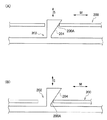
図30(A)(B)に示されるように、移動部材200には、傾斜する面は設けられておらず、これに代えて、レール部材202に回転軸方向に対して傾斜した傾斜面部204が設けられている。   As shown in FIGS. 30A and 30B, the moving member 200 is not provided with an inclined surface. Instead, the inclined member 204 is inclined on the rail member 202 with respect to the rotation axis direction. Is provided.

詳細には、回転軸方向(図中矢印M方向)に移動する移動部材200には、傾斜面部204を押圧する押圧部200Aが設けられており、この押圧部200Aで傾斜面部204を押圧することで、レール部材202が接離方向(図中矢印S方向)に移動するようになっている。   Specifically, the moving member 200 that moves in the rotation axis direction (the direction of the arrow M in the figure) is provided with a pressing portion 200A that presses the inclined surface portion 204, and the inclined surface portion 204 is pressed by the pressing portion 200A. Thus, the rail member 202 moves in the contact / separation direction (the direction of arrow S in the figure).

なお、本発明を特定の実施形態について詳細に説明したが、本発明はかかる実施形態に限定されるものではなく、本発明の範囲内にて他の種々の実施形態が可能であることは当業者にとって明らかである。例えば、上記実施形態では、傾斜面部126を移動部材124に一体的に形成したが、傾斜面部を移動部材に一体的に形成しなくてもよい(別体としてもよい)。   Although the present invention has been described in detail with respect to specific embodiments, the present invention is not limited to such embodiments, and various other embodiments are possible within the scope of the present invention. It is clear to the contractor. For example, in the above-described embodiment, the inclined surface portion 126 is formed integrally with the moving member 124, but the inclined surface portion may not be formed integrally with the moving member (may be separate).

なお、上記実施形態では、湾曲したグリッド108を用いて説明したが、平面状のグリッド等であってもよい。   In the above embodiment, the curved grid 108 has been described, but a planar grid or the like may be used.

10 画像形成装置
62 像保持体
64 帯電装置
100 帯電器
104 放電ワイヤ(放電電極の一例)
114 レール部材(支持部材の一例)
118A 接触部
124 移動部材
126 傾斜面部
142 センサ(検知手段)
200 移動部材
200A 押圧部
202 レール部材
204 傾斜面部
DESCRIPTION OF SYMBOLS 10 Image forming apparatus 62 Image holding body 64 Charging apparatus 100 Charger 104 Discharge wire (an example of discharge electrode)
114 Rail member (an example of a support member)
118A Contact part 124 Moving member 126 Inclined surface part 142 Sensor (detection means)
200 Moving member 200A Pressing portion 202 Rail member 204 Inclined surface portion

Claims (5)

回転可能に支持されて表面に静電潜像が形成される像保持体に対向すると共に、前記像保持体の回転軸方向に延びる放電電極を備え、前記放電電極に電圧を印加して前記像保持体の表面を帯電させる帯電器と、
前記帯電器を前記像保持体の表面に接近させて前記像保持体の表面を帯電させる帯電位置と、前記像保持体の表面から離間して退避させる退避位置とに接離させる接離手段と、を備え、
前記接離手段は、
前記接離手段によって退避位置に配置された前記帯電器を装置本体に対して前記像保持体の回転軸方向に着脱自在に支持する支持部材と、
駆動源からの駆動力が伝達され、前記像保持体の回転軸方向に移動する移動部材と、
前記移動部材の前記回転軸方向の移動力を、前記支持部材に前記接離方向の少なくとも一方の移動力として伝達する伝達手段と、
を備える帯電装置。
A discharge electrode that is rotatably supported and faces an image carrier on which an electrostatic latent image is formed is provided. The discharge electrode extends in a rotation axis direction of the image carrier, and a voltage is applied to the discharge electrode to apply the image. A charger for charging the surface of the holder;
Contact / separation means for bringing the charger close to the surface of the image carrier and charging the surface of the image carrier and a retraction position for retreating away from the surface of the image carrier; With
The contacting / separating means includes
A support member that removably supports the charger disposed in the retracted position by the contact / separation means with respect to the apparatus main body in the rotation axis direction of the image carrier;
A moving member that is transmitted with a driving force from a driving source and moves in the direction of the rotation axis of the image carrier;
Transmitting means for transmitting the moving force of the moving member in the rotational axis direction to the support member as at least one moving force in the contact / separation direction;
A charging device comprising:
前記伝達手段は、
前記移動部材に設けられ、前記像保持体の表面からの距離が異なるように前記回転軸方向に対して傾斜した傾斜面部と、
前記支持部材に設けられ、前記傾斜面部に接すると共に、前記移動部材を前記回転軸方向に移動させると、前記傾斜面部に沿って前記接離方向に移動して前記像保持体から接離する接離部と、
を備える請求項1に記載の帯電装置。
The transmission means includes
An inclined surface portion provided on the moving member and inclined with respect to the rotation axis direction so that the distance from the surface of the image carrier is different;
Provided on the support member and in contact with the inclined surface portion, and when the moving member is moved in the direction of the rotation axis, the contact member moves in the contact / separation direction along the inclined surface portion and contacts and separates from the image carrier A remote part,
The charging device according to claim 1, comprising:
前記伝達手段は、
前記支持部材に設けられ、前記像保持体の表面からの距離が異なるように前記回転軸方向に対して傾斜した傾斜面部と、
前記移動部材に設けられ、前記傾斜面部に接すると共に、前記移動部材を前記回転軸方向に移動させると、前記傾斜面部を押圧して前記傾斜面部を前記接離方向に移動させる押圧部と、
を備える請求項1に記載の帯電装置。
The transmission means includes
An inclined surface provided on the support member and inclined with respect to the rotation axis direction so that the distance from the surface of the image carrier is different;
A pressing portion that is provided on the moving member and contacts the inclined surface portion, and when the moving member is moved in the rotation axis direction, presses the inclined surface portion to move the inclined surface portion in the contact / separation direction;
The charging device according to claim 1, comprising:
前記移動部材の移動位置により、前記帯電器が前記像保持体に接近したことを検知する検知手段が設けられる請求項1〜3の何れか1項に記載の帯電装置。   4. The charging device according to claim 1, further comprising a detecting unit configured to detect that the charger has approached the image holding member based on a moving position of the moving member. 請求項1〜4の何れか1項に記載の帯電装置と、
前記帯電装置により表面が帯電される像保持体と、
を備える画像形成装置。
The charging device according to any one of claims 1 to 4,
An image carrier whose surface is charged by the charging device;
An image forming apparatus comprising:
JP2011031052A 2011-02-16 2011-02-16 Charging device, image forming device Active JP5742278B2 (en)

Priority Applications (3)

Application Number Priority Date Filing Date Title
JP2011031052A JP5742278B2 (en) 2011-02-16 2011-02-16 Charging device, image forming device
US13/198,404 US8644731B2 (en) 2011-02-16 2011-08-04 Charging device and image forming apparatus
CN201110303162.9A CN102645865B (en) 2011-02-16 2011-09-30 Charging unit and image forming apparatus

Applications Claiming Priority (1)

Application Number Priority Date Filing Date Title
JP2011031052A JP5742278B2 (en) 2011-02-16 2011-02-16 Charging device, image forming device

Publications (2)

Publication Number Publication Date
JP2012168460A true JP2012168460A (en) 2012-09-06
JP5742278B2 JP5742278B2 (en) 2015-07-01

Family

ID=46636970

Family Applications (1)

Application Number Title Priority Date Filing Date
JP2011031052A Active JP5742278B2 (en) 2011-02-16 2011-02-16 Charging device, image forming device

Country Status (3)

Country Link
US (1) US8644731B2 (en)
JP (1) JP5742278B2 (en)
CN (1) CN102645865B (en)

Cited By (1)

* Cited by examiner, † Cited by third party
Publication number Priority date Publication date Assignee Title
WO2015060464A1 (en) * 2013-10-25 2015-04-30 キヤノン株式会社 Image forming device

Citations (5)

* Cited by examiner, † Cited by third party
Publication number Priority date Publication date Assignee Title
JPS5965863A (en) * 1982-10-07 1984-04-14 Canon Inc Attachment supporting structure of electrifier on picture forming device or the like
JPH07302007A (en) * 1994-04-28 1995-11-14 Canon Inc Image forming device
JP2000194202A (en) * 1998-12-28 2000-07-14 Canon Inc Image forming device
JP2000227700A (en) * 1999-02-05 2000-08-15 Ricoh Co Ltd Image forming device
JP2006184838A (en) * 2004-11-30 2006-07-13 Kyocera Mita Corp Charger and image forming apparatus equipped with the same

Family Cites Families (7)

* Cited by examiner, † Cited by third party
Publication number Priority date Publication date Assignee Title
JPS63267973A (en) 1987-04-27 1988-11-04 Canon Inc Image forming device
US5095335A (en) * 1989-09-19 1992-03-10 Canon Kabushiki Kaisha Copier with retractable charging unit to prevent damage to drum when removing process cartridge
JP2948430B2 (en) * 1993-01-11 1999-09-13 三田工業株式会社 Advancing / retracting mechanism of charged charger
JPH0862950A (en) 1994-08-23 1996-03-08 Minolta Co Ltd Scorotron system electrifier
US7769314B2 (en) * 2007-02-20 2010-08-03 Fuji Xerox Co., Ltd. Cleaning device and charging device, image holding unit and image forming apparatus using same
US8050590B2 (en) * 2008-08-26 2011-11-01 Xerox Corporation Corona device grid cleaner
JP5849404B2 (en) * 2011-02-16 2016-01-27 富士ゼロックス株式会社 Image forming apparatus

Patent Citations (5)

* Cited by examiner, † Cited by third party
Publication number Priority date Publication date Assignee Title
JPS5965863A (en) * 1982-10-07 1984-04-14 Canon Inc Attachment supporting structure of electrifier on picture forming device or the like
JPH07302007A (en) * 1994-04-28 1995-11-14 Canon Inc Image forming device
JP2000194202A (en) * 1998-12-28 2000-07-14 Canon Inc Image forming device
JP2000227700A (en) * 1999-02-05 2000-08-15 Ricoh Co Ltd Image forming device
JP2006184838A (en) * 2004-11-30 2006-07-13 Kyocera Mita Corp Charger and image forming apparatus equipped with the same

Cited By (2)

* Cited by examiner, † Cited by third party
Publication number Priority date Publication date Assignee Title
WO2015060464A1 (en) * 2013-10-25 2015-04-30 キヤノン株式会社 Image forming device
US9766569B2 (en) 2013-10-25 2017-09-19 Canon Kabushiki Kaisha Image forming apparatus with corona charger cleaning

Also Published As

Publication number Publication date
CN102645865B (en) 2016-06-15
JP5742278B2 (en) 2015-07-01
US20120207513A1 (en) 2012-08-16
CN102645865A (en) 2012-08-22
US8644731B2 (en) 2014-02-04

Similar Documents

Publication Publication Date Title
JP5849404B2 (en) Image forming apparatus
JP5644391B2 (en) Electrical connection structure, image forming apparatus
JP5782750B2 (en) Charging device and image forming apparatus
JP5703857B2 (en) Cleaning device, charging device, and image forming apparatus
JP5880002B2 (en) Charging device, image forming device
JP5742278B2 (en) Charging device, image forming device
JP5742277B2 (en) Charging device, image forming device
JP5915965B2 (en) Charging device and image forming apparatus
US8422927B2 (en) Fixing device and image forming apparatus
JP5831799B2 (en) Image forming apparatus
JP2007093782A (en) Image forming apparatus and image forming method therefor
JP2006235033A (en) Image forming apparatus
JP5796739B2 (en) Image forming apparatus
JP5768630B2 (en) Image forming apparatus
JP5929686B2 (en) Fixing apparatus and image forming apparatus
JP2005099320A (en) Image forming apparatus
JP6036466B2 (en) Image forming apparatus
JP2013041032A (en) Fixing device and image forming apparatus
JP2012185299A (en) Charging device and image forming apparatus
JP2013109200A (en) Image forming apparatus
JP2005345940A (en) Image forming apparatus
JP2006227071A (en) Image forming apparatus
JP2013145346A (en) Image forming apparatus
US20130129387A1 (en) Control electrode, charging device, and image forming apparatus
JP2013148669A (en) Image forming apparatus

Legal Events

Date Code Title Description
A621 Written request for application examination

Free format text: JAPANESE INTERMEDIATE CODE: A621

Effective date: 20140121

A977 Report on retrieval

Free format text: JAPANESE INTERMEDIATE CODE: A971007

Effective date: 20141106

A131 Notification of reasons for refusal

Free format text: JAPANESE INTERMEDIATE CODE: A131

Effective date: 20141111

A521 Written amendment

Free format text: JAPANESE INTERMEDIATE CODE: A523

Effective date: 20150107

TRDD Decision of grant or rejection written
A01 Written decision to grant a patent or to grant a registration (utility model)

Free format text: JAPANESE INTERMEDIATE CODE: A01

Effective date: 20150407

A61 First payment of annual fees (during grant procedure)

Free format text: JAPANESE INTERMEDIATE CODE: A61

Effective date: 20150420

R150 Certificate of patent or registration of utility model

Ref document number: 5742278

Country of ref document: JP

Free format text: JAPANESE INTERMEDIATE CODE: R150

S533 Written request for registration of change of name

Free format text: JAPANESE INTERMEDIATE CODE: R313533

R350 Written notification of registration of transfer

Free format text: JAPANESE INTERMEDIATE CODE: R350