JP2012168155A - Wireless thermometer and wireless body temperature measuring system - Google Patents
Wireless thermometer and wireless body temperature measuring system Download PDFInfo
- Publication number
- JP2012168155A JP2012168155A JP2011171588A JP2011171588A JP2012168155A JP 2012168155 A JP2012168155 A JP 2012168155A JP 2011171588 A JP2011171588 A JP 2011171588A JP 2011171588 A JP2011171588 A JP 2011171588A JP 2012168155 A JP2012168155 A JP 2012168155A
- Authority
- JP
- Japan
- Prior art keywords
- temperature
- wireless thermometer
- wireless
- antenna
- unit
- Prior art date
- Legal status (The legal status is an assumption and is not a legal conclusion. Google has not performed a legal analysis and makes no representation as to the accuracy of the status listed.)
- Granted
Links
Images


Abstract
Description
本発明は、被検温体の体温によって定まる物理量を測定して当該物理量を外部装置に無線送信する無線式体温計および当該無線式体温計を備えた無線式体温測定システムに関する。 The present invention relates to a wireless thermometer that measures a physical quantity determined by the body temperature of a test body and wirelessly transmits the physical quantity to an external device, and a wireless body temperature measurement system including the wireless thermometer.
従来、深部体温を測定する装置が各種考案されており、その一つとして、特許文献1に示す装置がある。特許文献1に示す装置は、被検温体の表面に装着される体温計本体と、表示装置とを備える。体温計本体と表示装置との間では、無線通信が可能な構成となっている。
Conventionally, various devices for measuring deep body temperature have been devised, and one of them is the device shown in
特許文献1の体温計本体は、体表面側温度センサと外気側温度センサとを一つの組として備える。体表面側温度センサと外気側温度センサとは、所定の熱抵抗を有する断熱材を介在するように配置されている。そして、体温計本体は、体表面側温度センサが被検温体の表面に当接するように、被検温体に対して設置される。体表面側温度センサの温度検出結果と、外気側温度センサの温度検出結果とは、無線通信により、表示装置へ送信される。
The thermometer body of
特許文献1の表示装置は、体表面側温度センサの温度検出結果、外気側温度センサの温度検出結果、および、体表面側温度センサと外気側温度センサとの間の断熱材の熱抵抗に基づいて、深部体温を算出して表示する。
The display device of
しかしながら、上述の特許文献1に示す体温測定装置では、体表面側温度センサと外気側温度センサとが、導電性の電極パターンによって物理的に単一のアンテナに接続する構造を用いている。このため、体表面側温度センサと外気側温度センサとが導電性の電極パターンで接続されてしまう。
However, the body temperature measuring device shown in
したがって、体表面から体表面側温度センサ、外気側温度センサを介して、外気に熱が伝導する際に、断熱材のみでなく、導電性の電極パターンを介しても熱伝導してしまう。これにより、深部体温の算出結果の精度が低下してしまう。 Therefore, when heat is conducted from the body surface to the outside air through the body surface side temperature sensor and the outside air temperature sensor, heat conduction is performed not only through the heat insulating material but also through the conductive electrode pattern. Thereby, the precision of the calculation result of deep body temperature will fall.
この発明の目的は、精度良く深部体温を測定可能な無線式体温計および無線式体温測定システムを実現することにある。 An object of the present invention is to realize a wireless thermometer and a wireless body temperature measuring system capable of measuring a deep body temperature with high accuracy.
この発明は、被検温体の深部体温を測定するための無線式体温計に関する。本発明の無線式体温計は、断熱体、第1の温度検出手段、第2の温度検出手段、第1アンテナおよび第2アンテナを備える。断熱体は所定の熱抵抗率を有する材質によって形成されている。第1の温度検出手段は断熱体の一方面に配置されており、第2の温度検出手段は断熱体を介して一方面と対向する他方面に配置されている。第1アンテナは第1の温度検出手段から出力される第1検出信号を送信する。第2アンテナは第2の温度検出手段から出力される第2検出信号を送信する。このような構成の上で、第1アンテナと第2アンテナとは、それぞれ独立して個別に形成されている。 The present invention relates to a wireless thermometer for measuring a deep body temperature of a test temperature body. The wireless thermometer of the present invention includes a heat insulator, first temperature detection means, second temperature detection means, a first antenna, and a second antenna. The heat insulator is formed of a material having a predetermined thermal resistivity. The first temperature detection means is disposed on one surface of the heat insulator, and the second temperature detection means is disposed on the other surface facing the one surface through the heat insulator. The first antenna transmits a first detection signal output from the first temperature detection means. The second antenna transmits a second detection signal output from the second temperature detection means. On such a structure, the 1st antenna and the 2nd antenna are each formed independently independently.
この構成では、第1の温度検出手段と第2の温度検出手段とで共通のアンテナを用いない。したがって、第1の温度検出手段と第2の温度検出手段とが導電体で接続されない構造となる。これにより、第2の温度検出手段を被検温体の表面に密着させ、第1の温度検出手段を外気側とするように、無線式体温計を設置すれば、被検温体からの体温が外部に放熱される過程において、第2の温度検出手段と第1の温度検出手段との間では、断熱体のみを介して熱伝導される。 In this configuration, a common antenna is not used for the first temperature detection unit and the second temperature detection unit. Therefore, the first temperature detection unit and the second temperature detection unit are not connected by the conductor. As a result, if the wireless thermometer is installed so that the second temperature detection means is in close contact with the surface of the test temperature body and the first temperature detection means is on the outside air side, the body temperature from the test temperature body is externally exposed. In the process of radiating heat, heat is conducted between the second temperature detection means and the first temperature detection means only through the heat insulator.
また、この発明の無線式体温計では、第1の温度検出手段と第2の温度検出手段とが、それぞれ複数配設されている。 In the wireless thermometer according to the present invention, a plurality of first temperature detecting means and a plurality of second temperature detecting means are provided.
この構成では、二つの異なる熱伝達経路での温度検知結果が得られ、これら複数の深部体温を算出することが可能になる。したがって、より信頼性の高い深部体温を測定することができる。 In this configuration, temperature detection results in two different heat transfer paths can be obtained, and the plurality of deep body temperatures can be calculated. Therefore, the deep body temperature with higher reliability can be measured.
また、この発明の無線式体温計では、第1アンテナと第2アンテナとが、断熱体の一方面あるいは一方面と対向する他方面の領域内に配置されている。 Further, in the wireless thermometer of the present invention, the first antenna and the second antenna are arranged in a region of one surface of the heat insulator or the other surface facing the one surface.
この構成では、第1アンテナと第2アンテナが断熱体よりはみ出す領域に存在しない。したがって、アンテナを介して外部に直接放熱されることを抑制することができ、測定精度をより向上させることができる。 In this configuration, the first antenna and the second antenna do not exist in a region protruding from the heat insulator. Therefore, it is possible to suppress direct heat radiation to the outside via the antenna, and the measurement accuracy can be further improved.
また、この発明の無線式体温計では、第1アンテナと第2アンテナは、外部のアンテナに対して磁界結合する巻回形のコイルによって形成されている。 In the wireless thermometer of the present invention, the first antenna and the second antenna are formed by a wound coil that is magnetically coupled to an external antenna.
この構成では、近接式で磁界結合型(電磁誘導型)の無線通信を採用する場合の第1アンテナと第2アンテナの具体的構成を示している。この構成により、電波を使用する場合に対して、無線通信に対する被検温体の影響を低減することができるため、無線通信の精度を向上させることができる。 In this configuration, a specific configuration of the first antenna and the second antenna in the case of employing proximity and magnetic field coupling type (electromagnetic induction type) wireless communication is shown. With this configuration, since the influence of the test object on the wireless communication can be reduced when using radio waves, the accuracy of the wireless communication can be improved.
また、この発明の無線式体温計では、第1アンテナおよび第2アンテナよりも内径および外径が大きな巻回状導体を有し、該巻回状導体による共振周波数が第1検出信号および第2検出信号の周波数に略一致する中継アンテナを備える。当該中継アンテナの巻回状導体は、断熱体の外側面もしくは外側面よりも外方に、断熱体を囲むように配設されている。 In addition, the wireless thermometer of the present invention has a wound conductor having an inner diameter and an outer diameter larger than those of the first antenna and the second antenna, and the resonance frequency of the wound conductor has the first detection signal and the second detection frequency. A relay antenna that substantially matches the frequency of the signal is provided. The wound conductor of the relay antenna is disposed so as to surround the heat insulator outside the outer surface or the outer surface of the heat insulator.
この構成では、第1アンテナおよび第2アンテナによる第1検出信号および第2検出信号の送信に中継アンテナを利用でき、外部への放射効率を向上させ、通信効率を向上させることができる。 In this configuration, the relay antenna can be used for transmitting the first detection signal and the second detection signal by the first antenna and the second antenna, so that the radiation efficiency to the outside can be improved and the communication efficiency can be improved.
また、この発明の無線式体温計では、第1の温度検出手段は第1アンテナを構成するコイルの巻回形の中心側に配置されている。第2の温度検出手段は第2アンテナを構成するコイルの巻回形の中心側に配置されている。 In the wireless thermometer according to the present invention, the first temperature detecting means is arranged on the center side of the coiled shape of the first antenna. The second temperature detection means is arranged on the center side of the coiled shape of the second antenna.
この構成では、第1アンテナの占める領域内に第1の温度検出手段が配置され、第2アンテナの占める領域内に第2の温度検出手段が配置される。これにより、無線式体温計を省スペース化することができる。 In this configuration, the first temperature detection means is arranged in the area occupied by the first antenna, and the second temperature detection means is arranged in the area occupied by the second antenna. Thereby, a space-saving wireless thermometer can be achieved.
また、この発明の無線式体温計では、第1の温度検出手段と第2の温度検出手段は、外部からの無線信号によって動作するものであり、かつ第1アンテナと第2アンテナに直接接続されており、検出した温度を外部に伝達する機能を有する温度センサ素子である。 In the wireless thermometer of the present invention, the first temperature detecting means and the second temperature detecting means are operated by a radio signal from the outside and are directly connected to the first antenna and the second antenna. The temperature sensor element has a function of transmitting the detected temperature to the outside.
この構成では、温度センサを駆動させる駆動装置がない、すなわち、発熱体を有していない。さらに、温度センサがアンテナに直接接続されている。したがって、被検温体の温度をより正確に測定することができる。 In this configuration, there is no driving device for driving the temperature sensor, that is, no heating element is provided. Furthermore, a temperature sensor is directly connected to the antenna. Therefore, the temperature of the test warm body can be measured more accurately.
また、この発明の無線式体温計では、第1の温度検出手段および第2の温度検出手段は圧電共振子からなる。 In the wireless thermometer according to the present invention, the first temperature detecting means and the second temperature detecting means are composed of piezoelectric resonators.
この構成では、第1、第2の温度検出手段の具体例を示している。 This configuration shows a specific example of the first and second temperature detection means.
また、この発明の無線式体温計では、圧電共振子は水晶振動子である。また、この発明の無線式体温計では、圧電共振子は弾性表面波共振子である。 In the wireless thermometer of the present invention, the piezoelectric resonator is a crystal resonator. In the wireless thermometer of the present invention, the piezoelectric resonator is a surface acoustic wave resonator.
これらの構成では、圧電共振子のさらに具体的な例を示している。それぞれの素子の共振周波数およびアンテナの形状から、磁界結合による無線通信の場合には水晶振動子を利用した方が無線式体温計を簡素な構造で形成しやすく、電波による無線通信の場合には弾性表面波共振子を利用した方が無線式体温計を簡素な構造で形成しやすい。 These configurations show more specific examples of piezoelectric resonators. Due to the resonance frequency of each element and the shape of the antenna, it is easier to form a wireless thermometer with a simple structure when using wireless communication by magnetic field coupling, and it is elastic when using wireless communication using radio waves. Using a surface wave resonator makes it easier to form a wireless thermometer with a simple structure.
また、この発明の無線式体温計では、体温を算出する際に利用する校正用データを記憶させたRFIDを、第1の温度検出手段および第2の温度検出手段とは別に備える。 In addition, the wireless thermometer of the present invention includes an RFID storing calibration data used when calculating the body temperature, separately from the first temperature detection means and the second temperature detection means.
この構成では、校正用データを用いた高精度な体温計測が実現可能になる。 With this configuration, highly accurate body temperature measurement using calibration data can be realized.
また、この発明の無線式体温計では、校正用データは、第1の温度検出手段および第2の温度検出手段の温度と周波数の相関データもしくは当該相関データから算出される第1の補正係数を含む。 In the wireless thermometer of the present invention, the calibration data includes temperature-frequency correlation data of the first temperature detection means and the second temperature detection means, or a first correction coefficient calculated from the correlation data. .
また、この発明の無線式体温計では、校正用データは、断熱体の熱抵抗もしくは当該熱抵抗から算出される第2の補正係数を含む。 In the wireless thermometer of the present invention, the calibration data includes the thermal resistance of the heat insulator or the second correction coefficient calculated from the thermal resistance.
これらの構成では、校正用データの具体的な内容例を示している。 In these configurations, specific examples of contents of calibration data are shown.
また、この発明の無線式体温計では、第1の温度検出手段および第2の温度検出手段の少なくとも一方は、温度センサを内蔵するRFID−ICである。 In the wireless thermometer according to the present invention, at least one of the first temperature detection means and the second temperature detection means is an RFID-IC with a built-in temperature sensor.
この構成では、RFID−ICによるID送信機能が追加されるので、第1検出信号および第2検出信号の少なくとも一方に対して識別IDを付加することができる。 In this configuration, since an ID transmission function by RFID-IC is added, an identification ID can be added to at least one of the first detection signal and the second detection signal.
また、この発明の無線式体温計では、RFID−ICは、体温を算出する際に利用する校正用データを記憶している。 In the wireless thermometer of the present invention, the RFID-IC stores calibration data used when calculating the body temperature.
この構成では、校正用データも送信できるので、当該校正用データを用いた高精度な体温計測に利用できる。 In this configuration, calibration data can also be transmitted, so that it can be used for highly accurate body temperature measurement using the calibration data.
また、この発明は、上述の無線式体温計と、該無線式体温計に対して、第1の温度検出手段および第2の温度検出手段に与える入力信号の送信、第1検出信号および第2検出信号の受信を行う親機と、を備えた無線式体温測定システムに関する。この無線式体温測定システムの無線式体温計は被検温体の表面に装着されている。親機は、無線式体温計と無線通信する親機側アンテナ部と、第1検出信号および第2検出信号に基づいて被検温体の深部体温の計測を行う計測用処理部と、を備える。 The present invention also provides the above-described wireless thermometer, transmission of input signals to the first temperature detecting means and the second temperature detecting means, the first detection signal, and the second detection signal to the wireless thermometer. A wireless body temperature measuring system comprising: The wireless thermometer of this wireless body temperature measuring system is mounted on the surface of the body to be examined. The parent device includes a parent device-side antenna unit that wirelessly communicates with a wireless thermometer, and a measurement processing unit that measures the deep body temperature of the temperature to be detected based on the first detection signal and the second detection signal.
この構成では、上述の無線式体温計を含む無線式体温測定システムについて示している。このように上述の無線式体温計を用いることで、深部体温を精度良く測定することができる。 In this configuration, a wireless body temperature measuring system including the above-described wireless body thermometer is shown. Thus, the deep body temperature can be accurately measured by using the above-described wireless thermometer.
また、この発明の無線式体温測定システムでは、親機の計測用処理部は、無線式体温計から受信した第1検出信号および第2検出信号と校正用データとを用いて、被検温体の深部体温の計測を行う。 In the wireless body temperature measurement system of the present invention, the measurement processing unit of the master unit uses the first detection signal, the second detection signal, and the calibration data received from the wireless thermometer, and uses the first detection signal and the calibration data. Measure body temperature.
この構成では、無線式体温計から取得した校正用データを用いることで、より高精度に、被検温体の深部体温を計測できる。 In this configuration, by using the calibration data acquired from the wireless thermometer, the deep body temperature of the test body can be measured with higher accuracy.
この発明によれば、精度良く深部体温を測定可能な無線式体温計を実現することができる。 According to the present invention, it is possible to realize a wireless thermometer that can accurately measure the deep body temperature.
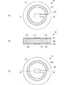
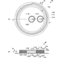
本発明の第1の実施形態に係る無線式体温計および無線式体温測定システムについて、図を参照して説明する。本実施形態では、磁界結合により無線式体温計10と携帯型親端末20とで通信を行う場合を示す。なお、通信様式は、磁界結合に限らず、電界結合や電波等、その他の無線通信方式によるものであってもよい。図1は本実施形態に係る無線式体温計10の構成を示す図である。図1(A)は上面断熱体141を省略した状態での上面図、図1(B)は側面断面図、図1(C)は下面断熱体142を省略した状態での下面図である。
A wireless thermometer and a wireless body temperature measuring system according to a first embodiment of the present invention will be described with reference to the drawings. In the present embodiment, a case where communication is performed between the
無線式体温計10は、可撓性、絶縁性を有するとともに、所定の熱抵抗率ρTを有する断熱体130を備える。断熱体130は、平面視して(上面側もしくは下面側から見て)円形であり、所定の厚みDを有する。断熱体130は、被検温体の熱抵抗率と略同じ熱抵抗率ρTの材質を用いている。
断熱体130の上面(一方面)には、略全面に亘る領域に対して、巻回状のコイル電極121が形成されている。コイル電極121は、無線式体温計10と携帯型親端末20との間で磁界結合による通信を行う第1周波数に応じた形状で形成されている。このコイル電極121が本発明の第1アンテナに相当する。
On the upper surface (one surface) of the
断熱体130の上面におけるコイル電極121の巻回形を平面視した略中心には、水晶振動子111が配設されている。水晶振動子111とコイル電極121とは、導電性の電極パターンにより接続されている。
A
水晶振動子111は、感知温度に応じて所定の共振周波数fp1で共振する素子である。この水晶振動子111が本発明の第1の温度検出手段に相当する。
The
そして、断熱体130の上面には、コイル電極121および水晶振動子111を保護する上面断熱体141が配設されている。この際、上面断熱体141は、水晶振動子111の表面が露出するように配設しても良く、水晶振動子111の表面を覆うように配設してもよい。なお、この上面断熱体141は設置を省略することもできる。
An upper
断熱体130の下面(他方面)には、略全面に亘る領域に対して、巻回状のコイル電極122が形成されている。コイル電極122は、無線式体温計10と携帯型親端末20との間で磁界結合による通信を行う第2周波数に応じた形状で形成されている。この際、第2周波数は、上述の第1周波数とは異なる周波数に設定されている。このコイル電極122が本発明の第2アンテナに相当する。すなわち、第1アンテナと第2アンテナとでは、異なる周波数帯域で無線通信を行うように、コイル電極121,122が形成されている。ただし、第1周波数と第2周波数が近接するように設定した場合は、コイル電極121と122は同一の形状で形成することが可能である。
On the lower surface (the other surface) of the
断熱体130の下面におけるコイル電極122の巻回形を平面視した略中心には、水晶振動子112が配設されている。この際、水晶振動子112は、平面視して水晶振動子111と略重なり合う位置に配置される。水晶振動子112とコイル電極122とは、導電性の電極パターンにより接続されている。
A
水晶振動子112は、感知温度に応じて上述の水晶振動子111とは異なる所定の共振周波数fp2で共振する素子である。特に、本実施形態の無線式体温計10では、当該無線式体温計10で検出する温度範囲において、水晶振動子111が取り得る周波数帯域と水晶振動子112が取り得る周波数帯域とが異なるように、水晶振動子111、112を選択する。この水晶振動子112が本発明の第2の温度検出手段に相当する。
The
そして、断熱体130の下面には、コイル電極122および水晶振動子112を保護する下面断熱体142が配設されている。この際、下面断熱体142は、水晶振動子112の表面が露出するように配設する。下面断熱体142として、体表面への吸着性が良好な材料を用いれば、検温時に体表面から剥がれにくくなり、より円滑に体温測定を行うことができる。なお、この下面断熱体142は設置を省略することもできる。その場合、断熱体130を、体表面への吸着性が良好な材料としてもよい。
A lower
このように、本実施形態の無線式体温計10では、水晶振動子111に対してはコイル電極121がアンテナとなり、水晶振動子112に対しては、コイル電極122がアンテナとなる。言い換えれば、水晶振動子111,112毎に個別のアンテナが設けられている。これにより、水晶振動子111,112は、導電性の電極パターン、すなわち断熱体130と異なる熱伝導率を有する電極パターンにより電気的に接続されない。この結果、後述する各水晶振動子111,112の周波数(感知温度)と、断熱体130の熱抵抗率ρTおよび厚みDから得られる熱抵抗RTとを用いた深部温度の算出精度が向上する。
As described above, in the
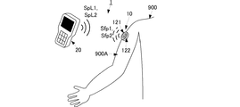
以上のような構成の無線式体温計10を、図2、図3に示すような無線式体温測定システム1に利用する。図2は本実施形態に係る無線式体温測定システム1の実施状況を示す図である。図3は本実施形態に係る無線式体温測定システム1の主要回路構成を示すブロック図である。
The
まず、水晶振動子112およびコイル電極122が配設された無線式体温計10の下面を、被検温体である人900の腕900Aに装着する。なお、本実施形態では、腕に装着する場合を示したが、検温したい箇所(例えば人900の胸部等)に装着すればよい。
First, the lower surface of the
このように人900に装着された無線式体温計10に対して、携帯型親端末20から第1パルス信号SpL1、第2パルス信号SpL2を送信する。この際、携帯型親端末20を、無線式体温計10のコイル電極121,122との間で磁界結合による通信が可能な距離に近づけて第1パルス信号SpL1、第2パルス信号SpL2送信する。
Thus, the first pulse signal SpL1 and the second pulse signal SpL2 are transmitted from the
第1パルス信号SpL1は、コイル電極121で受信され、水晶振動子111へ印加される。水晶振動子111は、第1パルス信号SpL1によって共振し、第1共振信号Sfp1を出力する。この第1共振信号Sfp1が本発明の第1検出信号に相当する。第1共振信号Sfp1はコイル電極121に伝送される。コイル電極121に伝送された第1共振信号Sfp1は、磁界結合により携帯型親端末20へ送信される。
The first pulse signal SpL1 is received by the
ここで、第1共振信号Sfp1の周波数fp1は水晶振動子111の感知する温度によって変化し、一つの共振周波数に対して一意に温度が決まっている。具体的には、共振周波数fp1は、検温部である人900の腕900Aの体温が熱抵抗率ρTで厚みDからなる断熱体130を介して外気側へ熱伝導された温度に応じて一意に決まり、当該共振周波数fp1の第1共振信号Sfp1が出力される。
Here, the frequency fp1 of the first resonance signal Sfp1 varies depending on the temperature sensed by the
第2パルス信号SpL2は、コイル電極122で受信され、水晶振動子112へ印加される。水晶振動子112は、第2パルス信号SpL2によって共振し、第2共振信号Sfp2を出力する。この第2共振信号Sfp2が本発明の第2検出信号に相当する。第2共振信号Sfp2はコイル電極122に伝送される。コイル電極122に伝送された第2共振信号Sfp2は、磁界結合により携帯型親端末20へ送信される。
The second pulse signal SpL2 is received by the
ここで、第2共振信号Sfp2の周波数fp2は水晶振動子112の感知する温度によって変化し、一つの共振周波数に対して一意に温度が決まっている。具体的には、共振周波数fp2は、検温部である人900の腕900Aの体温に応じて一意に決まり、当該共振周波数fp2の第2共振信号Sfp2が出力される。
Here, the frequency fp2 of the second resonance signal Sfp2 varies depending on the temperature sensed by the
携帯型親端末20は、制御部21、送信信号生成部22、送受信部23、親機側アンテナ24、計測部25、表示部26、および操作部27を備える。制御部21は、携帯型親端末20の全体制御を行う。また、制御部21は、操作部27からの操作入力に応じて各種の制御処理を実行する。例えば、操作部27から体温測定の操作入力を受けると、まず、送信信号生成部22へ第1パルス信号SpL1の生成制御を行う。
The
送信信号生成部22は、第1パルス信号SpL1の生成制御を受けると、第1の周波数の搬送波からなる第1パルス信号SpL1を生成し、送受信部23へ与える。具体的には、第1パルス信号SpL1の周波数成分が、当該無線式体温計10で検出される温度範囲において、水晶振動子111が取り得る周波数帯域と略同じになるように、搬送波周波数は、水晶振動子111の共振周波数に近い周波数に設定され、かつ帯域幅を決定するパルス幅(バースト時間)は適当な値に設定されている。
When the transmission
送受信部23は、第1パルス信号SpL1を親機側アンテナ24に出力する。親機側アンテナ24は、無線式体温計10のアンテナ部12と同様の構造からなり、第1パルス信号SpL1を放射する。
The transmitter /
親機側アンテナ24は、無線式体温計10のコイル電極121から放射された第1共振信号Sfp1を受信し、送受信部23へ出力する。送受信部23は、第1共振信号Sfp1を計測部25へ出力する。
The base-unit-
制御部21は、第1共振信号Sfp1の受信を確認後、もしくは送信信号生成部22へ第1パルス信号SpL1の生成制御から一定時間経過後、送信信号生成部22へ第2パルス信号SpL2の生成制御を行う。
The
送信信号生成部22は、第2パルス信号SpL2の生成制御を受けると、第1の周波数と異なる第2の周波数の搬送波からなる第2パルス信号SpL2を生成し、送受信部23へ与える。具体的には、第2パルス信号SpL2の周波数成分が、当該無線式体温計10で検出する温度範囲において、水晶振動子112が取り得る周波数帯域と略同じとなるように、この第2パルス信号SpL2の搬送波周波数は、水晶振動子112の共振周波数に近い周波数に設定され、かつ帯域幅を決定するパルス幅(バースト時間)は適当な値に設定されている。
When the transmission
親機側アンテナ24は、無線式体温計10のコイル電極121から放射された第2共振信号Sfp2を受信し、送受信部23へ出力する。送受信部23は、第2共振信号Sfp2を計測部25へ出力する。
The base-unit-
計測部25は、周波数変換部251、温度検出部252、および体温算出部253を備える。周波数変換部251は、FFT処理等により、時間軸の第1共振信号Sfp1および第2共振信号Sfp2からそれぞれ周波数スペクトルを取得する。なお、本実施形態では第1共振信号Sfp1と第2共振信号Sfp2を別々に読み取る場合を示した。しかしながら、当該無線式体温計10で検出する温度範囲において、水晶振動子111が取り得る周波数帯域と水晶振動子112が取り得る周波数帯域をできるだけ近づけておき、かつ、2つの周波数帯域を含む広い周波数成分を持ったパルス信号を送信すれば、一回の送受信で、第1共振信号Sfp1と第2共振信号Sfp2を同時に測定することができる。
The
温度検出部252には、第1共振信号Sfp1の周波数と温度との関係、および第2共振信号Sfp2の周波数と温度との関係が予め記憶されている。
The
温度検出部252は、第1共振信号Sfp1の周波数スペクトルピークを検出し、当該ピーク周波数fp1に関連付けられた温度を、外気側温度Tsとして出力する。
The
温度検出部252は、第2共振信号Sfp2の周波数スペクトルピークを検出し、当該ピーク周波数fp2に関連付けられた温度を、体表面温度Tbとして出力する。
The
体温算出部253は、外気側温度Ts、体表面温度Tb、水晶振動子111、水晶振動子112間の断熱材130熱抵抗RTと、あらかじめ記憶している皮下組織の熱抵抗Ruとに基づいて、次式から被検温体の深部体温Tdを算出する。
The body
Td=Ts+(RT+Ru)・(Tb−Ts)/RT
算出された深部体温Tdは、表示部26および記憶部(図示せず)へ出力される。表示部26は深部体温測定結果を表示する。
Td = Ts + (R T + R u ) · (Tb−Ts) / R T
The calculated deep body temperature Td is output to the
以上のような構成により、携帯型親端末20により、遠隔で体温検出トリガを与えるだけで、人900の深部体温を測定することができる。
With the configuration as described above, the deep body temperature of the
そして、本実施形態の構成を用いることで、体温が外気へ放射されるまでの過程における、体表面温度Tbを検知する水晶振動子112と外気側温度Tsを検知する水晶振動子111との間の熱の伝搬は、断熱体130のみを介する。したがって、上述の深部体温Tdの算出式の元となる熱伝搬モデルと正確に一致するので、深部体温Tdを精度よく算出することができる。
Then, by using the configuration of this embodiment, between the
なお、本実施形態の説明では、水晶振動子111,112の表面が外部に露出する例を示したが、図4に示すような構成を用いてもよい。図4は本実施形態に係る無線式体温計10の変形例である無線式体温計10’の構成を示す図である。
In the description of the present embodiment, an example in which the surfaces of the
無線式体温計10’は、断熱材130とは別の断熱体151で、図1に示した無線式体温計10を覆った構成を備える。断熱体151は、断熱体130および皮下組織に対して十分に大きい熱抵抗率を有する材料からなることが望ましい。
The
断熱体151は、体温計としてのコアとなる断熱体130の水晶振動子111が配置された側の面(外気側となる上面)および側面(円周面)を覆う形状からなる。
The
このような構成とすることで、外気の影響を小さくすることが可能になり、外気温の急激な変化が起こる使用状況下では、より深部体温の算出精度を高めることができる。 By adopting such a configuration, it becomes possible to reduce the influence of the outside air, and it is possible to further improve the calculation accuracy of the deep body temperature under use conditions in which a sudden change in the outside air temperature occurs.
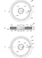
次に、第2の実施形態に係る無線式体温計について、図を参照して説明する。図5は、本実施形態に係る無線式体温計10Aの構成を示す図である。図5(A)は上面断熱体141を省略した状態での上面図、図5(B)は側面断面図、図5(C)は下面断熱体142を省略した状態での下面図である。
Next, a wireless thermometer according to the second embodiment will be described with reference to the drawings. FIG. 5 is a diagram showing a configuration of a
第1の実施形態に示した無線式体温計10、10’は、外気側と体表面側とでそれぞれ一つの水晶振動子を配置し、これらの組を用いて深部体温を測定するものであった。しかしながら、本実施形態の無線式体温計10Aは、外気側と体表面側との水晶振動子の組を複数設けたものである。なお、本実施形態では、具体的に外気側と体表面側との水晶振動子の組を二組設けた例を示しているが、三組以上であってもよい。
The
コアとなる断熱体は、中央部に平面視して所定面積となる断熱体130Bを備えるとともに、平面視して当該断熱体130Bの周囲を埋めるように配置された断熱体130Aを備える。
The heat insulator serving as a core includes a
断熱体130Aの上面には、巻回形状のコイル電極121Aが形成されるとともに、当該コイル電極121Aを平面した略中央には水晶振動子111Aが配置されている。コイル電極121Aと水晶振動子111Aは導電性の電極パターンにより接続されている。
A
断熱体130Aの下面には、巻回形状のコイル電極122Aが形成されるとともに、当該コイル電極122Aを平面した略中央には水晶振動子112Aが配置されている。この際、水晶振動子112Aは、平面視して水晶振動子111Aと重なりあうように配置されている。コイル電極122Aと水晶振動子112Aは導電性の電極パターンにより接続されている。この構成により、深部体温を測定する一組のアンテナ付き水晶振動子群が実現される。
A
断熱体130Bの上面には、巻回形状のコイル電極121Bが形成されるとともに、当該コイル電極121Bを平面した略中央には水晶振動子111Bが配置されている。コイル電極121Bと水晶振動子111Bは導電性の電極パターンにより接続されている。
A
断熱体130Bの下面には、巻回形状のコイル電極122Bが形成されるとともに、当該コイル電極122Bを平面した略中央には水晶振動子112Bが配置されている。この際、水晶振動子112Bは、平面視して水晶振動子111Bと重なりあうように配置されている。コイル電極122Bと水晶振動子112Bは導電性の電極パターンにより接続されている。この構成により、深部体温を測定するもう一組のアンテナ付き水晶振動子群が実現される。
A
なお、各水晶振動子111A,112A,111B,112Bは検知対象温度範囲において、共振周波数が重なり合わないようにする。これにより、携帯型親端末が、各水晶振動子111A,112A,111B,112Bからの検出信号を、容易に識別できる。
Note that the resonance frequencies of the
そして、本実施形態に示すように、二つの異なる熱伝達経路での温度検知結果に基づいて、深部体温を算出することで、より信頼性の高い深部体温を測定することができる。 Then, as shown in the present embodiment, the deep body temperature can be measured with higher reliability by calculating the deep body temperature based on the temperature detection results in two different heat transfer paths.
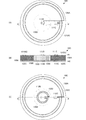
次に、第3の実施形態に係る無線式体温計について図を参照して説明する。図6は、本実施形態に係る無線式体温計10Bの構成を示す図である。図6(A)は上面断熱体141を省略した状態での上面図、図6(B)は側面断面図、図6(C)は下面断熱体142を省略した状態での下面図である。
Next, a wireless thermometer according to a third embodiment will be described with reference to the drawings. FIG. 6 is a diagram showing a configuration of a
第2の実施形態に示した無線式体温計10Aでは、各アンテナを構成するコイル電極121A,121B,122A,122Bの形状が略同じ場合を示した。しかしながら、本実施形態の無線式体温計10Bでは、同一面上に、巻回する径の大きなコイル電極と、巻回する径の小さなコイル電極とを備える。なお、断熱体130A,130Bの構成は第2の実施形態と同じである。
In the
断熱体130Aの上面には、巻回形状のコイル電極121Cが形成されている。コイル電極121Cは、断熱体130Aの外周近傍で巻回するように、大きな径で形成されている。当該コイル電極121Cを平面した内側で断熱体130A表面となる領域の所定位置には水晶振動子111Cが配置されている。コイル電極121Cと水晶振動子111Cは導電性の電極パターンにより接続されている。
A
断熱体130Aの下面には、巻回形状のコイル電極122Cが形成されている。コイル電極122Cは、断熱体130Aの外周近傍で巻回するように、大きな径で形成されている。当該コイル電極122Cを平面した内側で断熱体130A表面となる領域の所定位置には水晶振動子112Cが配置されている。
A
この際、水晶振動子112Cは、平面視して水晶振動子111Cと重なりあうように配置されている。コイル電極122Cと水晶振動子112Cは導電性の電極パターンにより接続されている。この構成により、深部体温を測定する一組のアンテナ付き水晶振動子群が実現される。
At this time, the
断熱体130Bの上面には、第2の実施形態と同様に、巻回形状のコイル電極121Bが形成されるとともに、当該コイル電極121Bを平面した略中央には水晶振動子111Bが配置されている。コイル電極121Bと水晶振動子111Bは導電性の電極パターンにより接続されている。
A
断熱体130Bの下面には、第2の実施形態と同様に、巻回形状のコイル電極122Bが形成されるとともに、当該コイル電極122Bを平面した略中央には水晶振動子112Bが配置されている。この際、水晶振動子112Bは、平面視して水晶振動子111Bと重なりあうように配置されている。コイル電極122Bと水晶振動子112Bは導電性の電極パターンにより接続されている。この構成により、深部体温を測定するもう一組のアンテナ付き水晶振動子群が実現される。
A
なお、各水晶振動子111B,112B,111C,112Cは検知対象温度範囲において、共振周波数が重なり合わないようにする。これにより、携帯型親端末が、各水晶振動子111B,112B,111C,112Cからの検出信号を、容易に識別できる。
Note that the resonance frequencies of the
そして、本実施形態の構成を用いても、二つの異なる熱伝達経路での温度検知結果に基づいて、深部体温を算出することができる。これにより、第2の実施形態と同様に、より信頼性の高い深部体温を測定することができる。 And even if the structure of this embodiment is used, based on the temperature detection result in two different heat transfer paths, the deep body temperature can be calculated. Thereby, similarly to 2nd Embodiment, the deep part body temperature with higher reliability can be measured.
次に、第4の実施形態に係る無線式体温計について、図を参照して説明する。図7は、本実施形態に係る無線式体温計10Cの構成を示す図である。図7(A)は上面断熱体141を省略した状態での上面図、図7(B)は側面断面図、図7(C)は下面断熱体142を省略した状態での下面図である。
Next, a wireless thermometer according to a fourth embodiment will be described with reference to the drawings. FIG. 7 is a diagram showing a configuration of a
本実施形態の無線式体温計10Cは、第3の実施形態に示した無線式体温計10Bに対して、同一面上に配置された水晶振動子111Bと水晶振動子111Cとで、コイル電極121BCを共有する点で異なる。すなわち、第3の実施形態で示したコイル電極121Cと同じく、断熱体130Aの外周近傍に大きな径で形成されたコイル電極121BCに対して、断熱体130A上に配置された水晶振動子111Cと、断熱体130B上に配置された水晶振動子111Bとを並列に接続する。この際、コイル電極121BCは、検温対象となる水晶振動子111Bおよび水晶振動子111Cの各周波数帯域で、磁界結合型の無線通信が可能な形状に形成する。
The
このような構成であっても、断熱体130A,130Bを挟んで配置される水晶振動子同士は導電性の電極パターンで接続されていないので、上述の各実施形態と同様に、精度良く深部体温を測定することができる。
Even in such a configuration, the quartz vibrators arranged with the
次に、第5の実施形態に係る無線式体温計について、図を参照して説明する。図8は本実施形態に係る無線式体温計10Dの構成を示す図である。図8(A)は上面断熱体141を省略した状態での上面図、図8(B)は側面断面図、図8(C)は下面断熱体142を省略した状態での下面図である。図9は校正用データの一例を示す表である。
Next, a wireless thermometer according to a fifth embodiment will be described with reference to the drawings. FIG. 8 is a diagram showing a configuration of a
本実施形態の無線式体温計10Dは、第1の実施形態に示した無線式体温計10に対して、さらにRFID160を追加した構成からなる。したがって、第1の実施形態と異なる構成のみを具体的に説明する。
The
送受のアンテナコイルをRFID160と水晶振動子111、112で共通化するため、RFID160の動作周波数fp3と水晶振動子111、112の共振周波数fp1,fp2は近接するように設定されている。具体的には、fp3=13.56MHzのHF帯RFIDを使用する場合は、fp1、fp2,は、13.56MHz±1MHzの範囲内とすることが好ましい。
Since the antenna coil for transmission / reception is shared by the
RFID160は、水晶振動子111と同様に、断熱体130の上面に配設されている。RFID160は、水晶振動子111が接続された巻回状のコイル電極121に、並列接続されている。すなわち、水晶振動子111とRFID160は、コイル電極121を共有する。
The
RFID160は、無線式体温計10Dに備えられた水晶振動子111,112、断熱材130に関する校正用データを記憶している。なお、これらの校正用データは、予め既知の雰囲気(特に温度)で測定された結果によって設定される。
The
図9に示すように、水晶振動子111の共振周波数fp1に関する校正用データは、予め設定した第1の温度TLにおける無線式体温計10Dに配設された水晶振動子111のピーク周波数(低温側ピーク周波数)f1Lと、第2の温度TH(>TL)における無線式体温計10Dに配設された水晶振動子111のピーク周波数(高温側ピーク周波数)f1Hである。したがって、水晶振動子111に関する校正用データとしては、第1の温度TLおよび低温側ピーク周波数f1Lの組(TL,f1L)、第2の温度THおよび高温側ピーク周波数f1Hの組(TH,f1H)からなる。
As shown in FIG. 9, the calibration data regarding the resonance frequency fp1 of the
同様に、水晶振動子112の共振周波数fp2に関する校正用データは、予め設定した第1の温度TLにおける無線式体温計10Dに配設された水晶振動子112のピーク周波数(低温側ピーク周波数)f2Lと、第2の温度TH(>TL)における無線式体温計10Dに配設された水晶振動子112のピーク周波数(高温側ピーク周波数)f2Hである。したがって、水晶振動子112に関する校正用データとしては、第1の温度TLおよび低温側ピーク周波数f2Lの組(TL,f2L)、第2の温度THおよび高温側ピーク周波数f2Hの組(TH,f2H)からなる。
Similarly, the calibration data relating to the resonance frequency fp2 of the
具体的には、RFIDに次のような値を入力する。
(TL,f1L)=(35.01、13.001)、
(TH,f1H)=(40.02、13.051)、
(TL,f2L)=(35.03、13.003)、
(TH,f2H)=(40.04、13.052)、
RT=2001。
Specifically, the following values are input to the RFID.
(TL, f1L) = (35.01, 13.001),
(TH, f1H) = (40.02, 13.051),
(TL, f2L) = (35.03, 13.003),
(TH, f2H) = (40.04, 13.052),
RT = 2001.
RFIDに入力する際は、入力値のばらつき範囲内の桁まで入力すれば十分であるので、例えば、以下のように入力してもよい。
(TL,f1L)=(1、01)、
(TH,f1H)=(2、51)、
(TL,f2L)=(3、03)、
(TH,f2H)=(4、52)、
RT=01。
このようにすることで、RFIDのメモリ使用量を削減できる。
When inputting to the RFID, it is sufficient to input up to a digit within the variation range of the input value. For example, the input may be as follows.
(TL, f1L) = (1, 01),
(TH, f1H) = (2, 51),
(TL, f2L) = (3, 03),
(TH, f2H) = (4, 52),
RT = 01.
By doing in this way, the amount of RFID memory used can be reduced.
なお、第1の温度TLと第2の温度THは、上述の関係TL<THが満たされればよいが、当該無線式体温計10Dの対象とする測定温度範囲の下限温度と上限温度に設定するとよい。
The first temperature TL and the second temperature TH need only satisfy the above-described relationship TL <TH, but may be set to the lower limit temperature and the upper limit temperature of the measurement temperature range targeted by the
また、断熱体130に関する校正用データは、無線式体温計10Dに配設された断熱体130の熱抵抗RTからなる。当該熱抵抗RTは、当該断熱体130の組成から得られる熱抵抗値をそのまま用いてもよいが、深部体温が既知な測定環境において、皮下組織の熱抵抗Ruを既知の固定値で、上述の水晶振動子111,112の特性が分かっている状態であれば、第1の実施形態に示した深部体温Tdの算出式を用いて算出することができる。
The calibration data related to the
RFID160は、これらの構成要素からなる校正用データを含むRFID返信信号Sreを親機からのRFID問い合わせ信号Sqに応じて親機に返信する。
The
次に、このようなRFID160を備えた無線式体温計10Dを含む無線式体温測定システム1Dについて、図を参照して説明する。この無線式体温測定システム1Dは、第1の実施形態に示した無線式体温測定システム10と体温測定に関する基本的構成および処理は同じであり、校正用データに関する箇所のみが異なる。したがって、異なる箇所のみを図10は本実施形態に係る無線式体温測定システム1Dの主要回路構成を示すブロック図である。
Next, a wireless body
親機側アンテナ24で上記校正用データを含むRFID返信信号Sreを受信すると、当該RFID返信信号Sreは、送受信部23Aを介して制御部21Aへ入力される。
When the base
制御部21Aは、RFID返信信号Sreを復調して、校正用データを取得し、計測部25Aへ与える。
The
計測部25Aの温度検出部252Aは、校正用データと、上述の実施形態の方法で取得した周波数変換部251からの第1共振信号Sfp1の周波数および第2共振信号Sfp2の周波数と、を用いて、外気側温度Tsおよび体表面温度Tbを算出する。
The
具体的には、温度検出部252Aは、校正用データの第1の温度TLおよび低温側ピーク周波数f1Lの組(TL,f1L)、および第2の温度THおよび高温側ピーク周波数f1Hの組(TH,f1H)から温度−周波数特性を線形補間で算出し、第1共振信号Sfp1の周波数に対応する温度を外気側温度Tsとして算出する。
Specifically, the
また、温度検出部252Aは、校正用データの第1の温度TLおよび低温側ピーク周波数f2Lの組(TL,f2L)、および第2の温度THおよび高温側ピーク周波数f2Hの組(TH,f2H)から温度−周波数特性を線形補間で算出し、第2共振信号Sfp2の周波数に対応する温度を外気側温度Tsとして算出する。
The
体温算出部253Aは、温度検出部252Aで校正用データを用いて算出された外気側温度Tsおよび外気側温度Tsと、校正用データの熱抵抗RTとを用いて、上述の第1の実施形態に示したように、深部体温Tdを算出する。
The body
以上のような構成を用いれば、無線式体温計10D毎に水晶振動子111,112および断熱体130に特性ばらつきがあっても、校正用データを用いて正確な体温測定が可能になる。
If the configuration as described above is used, accurate body temperature measurement can be performed using calibration data even if the
なお、本実施形態では、異なる二つの温度におけるピーク周波数を校正用データに用いる例を示したが、一つの温度におけるピーク周波数と線形補間用の補間係数(温度−周波数特性の勾配(傾き)に相当する値)との組や、上述の温度と周波数との相関から得られる補正係数を校正用データとして用いてもよい。また、断熱材の熱抵抗に関しても、当該熱抵抗から算出される補正係数を校正用データとして用いてもよい。さらには、RFID160の記憶容量を大きく取ることができれば、予め各水晶振動子111,112の共振周波数と深部体温Tdとの関係を記憶しておき、これらの関係を校正用データとして用いることもできる。
In this embodiment, an example in which peak frequencies at two different temperatures are used as calibration data is shown. However, the peak frequency at one temperature and an interpolation coefficient for linear interpolation (gradient (gradient) of temperature-frequency characteristics). A correction coefficient obtained from the above-described correlation between temperature and frequency may be used as calibration data. Further, regarding the thermal resistance of the heat insulating material, a correction coefficient calculated from the thermal resistance may be used as calibration data. Furthermore, if the storage capacity of the
また、本実施形態では、RFID160と水晶振動子111とを個別に設ける例を示したが、RFIDICとして温度センサを備えるものであれば、少なくとも断熱体の一方面に配設される水晶振動子だけでもRFIDICに置き換えればよい。
In the present embodiment, the example in which the
また、本実施形態では、水晶振動子111とRFID160とでアンテナを共通化したが、それぞれ個別のアンテナを設けてもよい。
In the present embodiment, the
また、本実施形態では、RFID160を断熱体130の外気側に設けた例を示したが、体表面側に設けることも可能である。
In the present embodiment, the example in which the
また、本実施形態では、体温測定と校正用データの読み取りを逐次個別に行う例を示したが、これらを同時に行うようにしてもよい。この場合、体温測定のための第1パルス信号SpL1は、RFID問い合わせ信号Sqと合成されてアンテナコイルより出力される。 Further, in the present embodiment, an example is shown in which body temperature measurement and calibration data are sequentially read individually, but these may be performed simultaneously. In this case, the first pulse signal SpL1 for body temperature measurement is combined with the RFID inquiry signal Sq and output from the antenna coil.
また、上述の説明では、断熱体の形状が、平面視して円形となる場合を示したが、その形状は円形に限るものではなく、平面視して四角形等の多角形となるような形状であってもよい。また、コイル電極についても、同様に、円で巻回する形状に限るものではなく、送受波する周波数帯域を上述のように適宜設定すれば、四角形等の多角形に巻回する形状であってもよい。 Further, in the above description, the case where the shape of the heat insulator is circular in a plan view is shown, but the shape is not limited to a circle, and the shape is a polygon such as a rectangle in plan view. It may be. Similarly, the coil electrode is not limited to a shape wound in a circle, and can be wound into a polygon such as a rectangle if the frequency band for transmitting and receiving waves is appropriately set as described above. Also good.
また、上述の説明では、磁界結合型のアンテナを用いた例を示したが、パッチアンテナ等の電波送受波型のアンテナを用いてもよい。 In the above description, an example using a magnetic field coupling type antenna has been described. However, a radio wave transmission / reception type antenna such as a patch antenna may be used.
また、上述の説明では、コイル電極の巻回形状の内側に水晶振動子を配置する例を示したが、巻回形状の外側に水晶振動子を配置してもよい。ただし、コイル電極の巻回形状の内側に水晶振動子を配置することで、無線式体温計を小型化することができる。 In the above description, the example in which the crystal resonator is arranged inside the winding shape of the coil electrode is shown, but the crystal resonator may be arranged outside the winding shape. However, the wireless thermometer can be miniaturized by arranging the crystal resonator inside the winding shape of the coil electrode.
また、上述の説明では、水晶振動子を例に説明したが、大きな周波数温度特性を有する圧電共振子であればよく、弾性表面波共振子を用いてもよい。特に、弾性表面波共振子を用いた場合、UHF帯などの電波通信用アンテナを小型にすることが可能な高い周波数に共振周波数を合わせることが水晶振動子に比べて容易であるので、電波による無線通信を行う無線式体温計を容易に製造することができる。 In the above description, the crystal resonator has been described as an example. However, any piezoelectric resonator having a large frequency temperature characteristic may be used, and a surface acoustic wave resonator may be used. In particular, when a surface acoustic wave resonator is used, it is easier to match the resonance frequency to a high frequency that can reduce the size of a radio wave communication antenna such as a UHF band as compared with a crystal resonator. A wireless thermometer that performs wireless communication can be easily manufactured.
また、上述の説明で示した深部体温の算出方法は一例であり、体表面側温度と外気側温度とを用いた他の算出方法を用いてもよい。 Moreover, the calculation method of the deep body temperature shown by the above-mentioned description is an example, and other calculation methods using the body surface side temperature and the outside air side temperature may be used.
また、上述の各実施形態、特に上述の第2の実施形態に示すように、複数の温度検出用の振動子、およびアンテナとなるコイル電極を、上面および下面に形成する場合には、コイル電極の形状が小さくなってしまうことがある。この場合、外部に対する電磁界結合が可能な距離が短くなってしまうことがある。このような場合には、次に示す第6の実施形態に示すような無線式体温計を用いればよい。図11は、本実施形態に係る無線式体温計40の構成を示す図である。図11(A)は上面断熱体141を省略した状態での上面図、図11(B)は側面断面図である。
In addition, as shown in each of the above-described embodiments, particularly the above-described second embodiment, a plurality of temperature detecting vibrators and a coil electrode to be an antenna are formed on the upper surface and the lower surface. May become smaller. In this case, the distance that can be electromagnetically coupled to the outside may be shortened. In such a case, a wireless thermometer as shown in the sixth embodiment shown below may be used. FIG. 11 is a diagram illustrating a configuration of the
図11に示すように、本実施形態の無線式体温計40は、第2の実施形態に示した無線式体温計10Aと、中継用アンテナ30とからなる。温度検出用の無線式体温計10Aは、第2の実施形態と同じであるので、中継用アンテナ30に関してのみ詳細に説明する。
As shown in FIG. 11, the
中継用アンテナ30は、絶縁性を有する円環形状のベースフィルム31と、巻回形からなるコイル電極32とを備える。ベースフィルム31の円環形状の内径は、無線式体温計10Aを平面視した外径よりも大きい。ベースフィルム31の幅、外径から内径を減算した長さは、コイル電極32が形成できる程度の所定長さである。なお、ベースフィルム31は、体表面への吸着性のよい材質であるとよい。
The
コイル電極32は、ベースフィルム31の上面に、ベースフィルム31の全周を周回する形状で形成されており、所定のインダクタンスおよび所定の寄生キャパシタンスが得られる形状に形成されている。この際、無線式体温計10Aと図示しない携帯型親端末とで送受信する信号の周波数帯域に、このコイル電極32の形状に基づくインダクタンスおよび寄生キャパシタンスによる共振周波数が重なるように、コイル電極32の電極幅、電極間隔および巻回数は決定される。なお、ここで、寄生キャパシタンスを用いる例を示したが、ベースフィルム31にチップコンデンサを実装し、コイル電極32に接続するような態様であってもよい。
The
このような構造からなる、中継アンテナ30の中空領域内に、無線式体温計10Aを配置する。具体的には、まず、検温部(人の腕等)に、中継アンテナ30を取り付ける。次に、中継アンテナ30の中空領域に露出した検温部に、無線式体温計10Aを取り付ける。これにより、中継アンテナ30の中空領域に無線式体温計10Aを維持した状態を実現できる。
The
このような構造からなる無線式体温計では、各コイル電極121A,121B,122A,122Bで送受信する信号が、中継アンテナ30を介することで、各コイル電極121A,121B,122A,122Bのみで送受信するよりも、遠距離まで送受信することが可能になる。逆に言えば、各コイル電極121A,121B,122A,122Bの形状を小さくしても、無線式体温計として必要な距離での送受信が可能になる。
In the wireless thermometer having such a structure, signals transmitted / received by the
また、中継アンテナ30を用いることで、各コイル電極121A,121B,122A,122Bに代えて、チップインダクタ、水晶振動子を含む温度センサ素子の外側面に周回して導体を巻きつけたコイル、水晶振動子を含む温度センサに内蔵したコイル等を用いることもできる。
Further, by using the
また、上述の説明では、中継アンテナ30と無線式体温計10Aとを別体で形成した例を示したが、例えば、中継アンテナ30のベースフィルム31と、無線式体温計10Aの下面断熱体142とを一体形成してもよい。
In the above description, the example in which the
また、上述の説明では、ベースフィルム31とコイル電極32から中継アンテナ30を形成する例を示したが、ベースフィルム31を省略して、コイル電極32を、無線式体温計10Aの外側面に沿って形成してもよい。
Moreover, although the example which forms the
また、上述の説明では、中継アンテナ30と無線式体温計10Aとの組合せを説明したが、他の実施形態の無線式体温計と中継アンテナ30を組み合わせることもできる。
In the above description, the combination of the
10,10’,10A,10B,10C,10D−無線式体温計、20,20A−携帯型親端末、21,21A−制御部、22−送信信号生成部、23,23A−送受信部、24−親機側アンテナ、25,25A−計測部、251−周波数変換部、252,252A−温度検出部、253,253A−体温算出部、26−表示部、27−操作部、
30−中継アンテナ、31−ベースフィルム、32−コイル電極、
111,111A,111B,111C,112,112A,112B,112C−水晶振動子、121,121A,121B,121C,121BC,122,122A,122B,122C−コイル電極、130,130A,130B−断熱体、141−上面断熱体、142−下面断熱体、151−断熱体、160−RFID、900−人、900A−腕、1,1D−無線式体温測定システム
10, 10 ′, 10A, 10B, 10C, 10D—wireless thermometer, 20, 20A—portable parent terminal, 21, 21A—control unit, 22—transmission signal generation unit, 23, 23A—transmission / reception unit, 24-parent Machine side antenna, 25,25A-measurement unit, 251-frequency conversion unit, 252,252A-temperature detection unit, 253,253A-body temperature calculation unit, 26-display unit, 27-operation unit,
30-relay antenna, 31-base film, 32-coil electrode,
111, 111A, 111B, 111C, 112, 112A, 112B, 112C—quartz crystal resonator, 121, 121A, 121B, 121C, 121BC, 122, 122A, 122B, 122C—coil electrode, 130, 130A, 130B—insulator, 141-upper surface insulator, 142-lower surface insulator, 151-insulator, 160-RFID, 900-person, 900A-arm, 1,1D-wireless body temperature measuring system
Claims (17)
該断熱体の一方面に配置された第1の温度検出手段と、
前記断熱体を介して前記一方面と対向する他方面に配置された第2の温度検出手段と、
前記第1の温度検出手段から出力される第1検出信号を送信する第1アンテナと、
前記第2の温度検出手段から出力される第2検出信号を送信する第2アンテナと、を備え、
前記第1アンテナと前記第2アンテナとが、それぞれ独立して個別に形成されている、無線式体温計。 A heat insulator formed of a material having a predetermined thermal resistivity;
First temperature detecting means disposed on one surface of the heat insulator;
A second temperature detecting means disposed on the other surface facing the one surface via the heat insulator;
A first antenna for transmitting a first detection signal output from the first temperature detection means;
A second antenna for transmitting a second detection signal output from the second temperature detection means,
The wireless thermometer, wherein the first antenna and the second antenna are independently formed individually.
前記第1の温度検出手段と前記第2の温度検出手段とが、それぞれ複数配設されている、無線式体温計。 The wireless thermometer according to claim 1,
A wireless thermometer in which a plurality of the first temperature detecting means and the second temperature detecting means are provided.
前記第1アンテナと前記第2アンテナとが、前記断熱体を平面視して、該断熱体の一方面あるいは該一方面と対向する他方面の領域内に配置されている、無線式体温計。 The wireless thermometer according to claim 1 or 2,
The wireless thermometer, wherein the first antenna and the second antenna are arranged in a region of one surface of the heat insulator or the other surface facing the one surface when the heat insulator is viewed in plan.
前記第1アンテナと前記第2アンテナは、外部のアンテナに対して磁界結合する巻回形のコイルによって形成されている、無線式体温計。 A wireless thermometer according to any one of claims 1 to 3,
The first antenna and the second antenna are wireless thermometers formed by a wound coil that is magnetically coupled to an external antenna.
前記第1アンテナおよび前記第2アンテナよりも内径および外径が大きな巻回状導体を有し、該巻回状導体による共振周波数が第1検出信号および第2検出信号の周波数に略一致する中継アンテナを備え、
前記巻回状導体は、前記断熱体の外側面もしくは外側面よりも外方に、前記断熱体を囲むように配設されている、無線式体温計。 The wireless thermometer according to claim 4, wherein
A relay having a wound conductor having an inner diameter and an outer diameter larger than those of the first antenna and the second antenna, and a resonance frequency of the wound conductor substantially matches a frequency of the first detection signal and the second detection signal. With an antenna,
The coiled conductor is a wireless thermometer that is disposed outside the outer surface or the outer surface of the heat insulator so as to surround the heat insulator.
前記第1の温度検出手段は、前記第1アンテナを構成する前記コイルの巻回形の中心側に配置され、
前記第2の温度検出手段は、前記第2アンテナを構成する前記コイルの巻回形の中心側に配置されている、無線式体温計。 The wireless thermometer according to claim 4 or 5, wherein
The first temperature detecting means is disposed on the center side of the coiled shape of the coil constituting the first antenna,
The said 2nd temperature detection means is a radio | wireless thermometer arrange | positioned in the center side of the winding shape of the said coil which comprises the said 2nd antenna.
前記第1の温度検出手段と前記第2の温度検出手段は、外部からの無線信号によって動作するものであり、かつ前記第1アンテナと前記第2アンテナに直接接続されており、検出した温度を外部に伝達する機能を有する温度センサ素子である、無線式体温計。 The wireless thermometer according to any one of claims 1 to 6,
The first temperature detecting means and the second temperature detecting means are operated by a radio signal from the outside, and are directly connected to the first antenna and the second antenna, and detect the detected temperature. A wireless thermometer that is a temperature sensor element having a function of transmitting to the outside.
前記第1の温度検出手段および前記第2の温度検出手段は圧電共振子からなる、無線式体温計。 The wireless thermometer according to claim 7,
The wireless thermometer, wherein the first temperature detecting means and the second temperature detecting means are made of piezoelectric resonators.
前記圧電共振子は水晶振動子である、無線式体温計。 The wireless thermometer according to claim 8, wherein
The wireless thermometer, wherein the piezoelectric resonator is a crystal resonator.
前記圧電共振子は弾性表面波共振子である、無線式体温計。 The wireless thermometer according to claim 8, wherein
The wireless thermometer, wherein the piezoelectric resonator is a surface acoustic wave resonator.
体温を算出する際に利用する校正用データを記憶させたRFIDを、前記第1の温度検出手段および前記第2の温度検出手段とは別に備える、無線式体温計。 A wireless thermometer according to any one of claims 8 to 10,
A wireless thermometer comprising an RFID storing calibration data used when calculating a body temperature, separately from the first temperature detecting means and the second temperature detecting means.
前記校正用データは、前記第1の温度検出手段および前記第2の温度検出手段の温度と周波数の相関データもしくは当該相関データから算出される第1の補正係数を含む、無線式体温計。 The wireless thermometer according to claim 11, wherein
The wireless thermometer, wherein the calibration data includes correlation data of temperature and frequency of the first temperature detection unit and the second temperature detection unit or a first correction coefficient calculated from the correlation data.
前記校正用データは、前記断熱体の熱抵抗もしくは当該熱抵抗から算出される第2の補正係数を含む、無線式体温計。 A wireless thermometer according to claim 11 or claim 12,
The calibration data includes a wireless thermometer including a thermal resistance of the heat insulator or a second correction coefficient calculated from the thermal resistance.
前記第1の温度検出手段および第2の温度検出手段の少なくとも一方は、温度センサを内蔵するRFID−ICである、無線式体温計。 The wireless thermometer according to claim 7,
At least one of the first temperature detection unit and the second temperature detection unit is a wireless thermometer, which is an RFID-IC incorporating a temperature sensor.
前記RFID−ICは、体温を算出する際に利用する校正用データを記憶している、無線式体温計。 The wireless thermometer according to claim 14,
The RFID-IC is a wireless thermometer that stores calibration data used when calculating a body temperature.
該無線式体温計に対して、前記第1の温度検出手段および前記第2の温度検出手段に与える入力信号の送信、前記第1検出信号および前記第2検出信号の受信を行う親機と、を備えた無線式体温測定システムであって、
前記無線式体温計は被検温体の表面に装着され、
前記親機は、前記無線式体温計と無線通信する親機側アンテナ部と、
前記第1検出信号および前記第2検出信号に基づいて、前記被検温体の深部体温の計測を行う計測用処理部と、を備える、無線式体温測定システム。 A wireless thermometer according to any one of claims 1 to 10 and claim 14,
A master unit for transmitting an input signal to the first temperature detection unit and the second temperature detection unit, and receiving the first detection signal and the second detection signal to the wireless thermometer; A wireless body temperature measurement system comprising:
The wireless thermometer is attached to the surface of a test body,
The base unit is a base unit side antenna unit that wirelessly communicates with the wireless thermometer,
A wireless body temperature measurement system, comprising: a measurement processing unit that measures a deep body temperature of the test body based on the first detection signal and the second detection signal.
該無線式体温計に対して、前記第1の温度検出手段および前記第2の温度検出手段に与える入力信号の送信、前記第1検出信号および前記第2検出信号の受信を行う親機と、を備えた無線式体温測定システムであって、
前記無線式体温計は被検温体の表面に装着され、
前記親機は、前記無線式体温計と無線通信する親機側アンテナ部と、
前記第1検出信号および前記第2検出信号と前記校正用データとを用いて、前記被検温体の深部体温の計測を行う計測用処理部と、を備える、無線式体温測定システム。 A wireless thermometer according to any one of claims 11, 12, 13 and 15,
A master unit for transmitting an input signal to the first temperature detection unit and the second temperature detection unit, and receiving the first detection signal and the second detection signal to the wireless thermometer; A wireless body temperature measurement system comprising:
The wireless thermometer is attached to the surface of a test body,
The base unit is a base unit side antenna unit that wirelessly communicates with the wireless thermometer,
A wireless body temperature measurement system, comprising: a measurement processing unit that measures the deep body temperature of the test body using the first detection signal, the second detection signal, and the calibration data.
Priority Applications (1)
| Application Number | Priority Date | Filing Date | Title |
|---|---|---|---|
| JP2011171588A JP5786533B2 (en) | 2010-09-24 | 2011-08-05 | Wireless thermometer and wireless thermometer measurement system |
Applications Claiming Priority (5)
| Application Number | Priority Date | Filing Date | Title |
|---|---|---|---|
| JP2010212962 | 2010-09-24 | ||
| JP2010212962 | 2010-09-24 | ||
| JP2011012803 | 2011-01-25 | ||
| JP2011012803 | 2011-01-25 | ||
| JP2011171588A JP5786533B2 (en) | 2010-09-24 | 2011-08-05 | Wireless thermometer and wireless thermometer measurement system |
Publications (2)
| Publication Number | Publication Date |
|---|---|
| JP2012168155A true JP2012168155A (en) | 2012-09-06 |
| JP5786533B2 JP5786533B2 (en) | 2015-09-30 |
Family
ID=46972441
Family Applications (1)
| Application Number | Title | Priority Date | Filing Date |
|---|---|---|---|
| JP2011171588A Active JP5786533B2 (en) | 2010-09-24 | 2011-08-05 | Wireless thermometer and wireless thermometer measurement system |
Country Status (1)
| Country | Link |
|---|---|
| JP (1) | JP5786533B2 (en) |
Cited By (5)
| Publication number | Priority date | Publication date | Assignee | Title |
|---|---|---|---|---|
| WO2013024568A1 (en) * | 2011-08-18 | 2013-02-21 | テルモ株式会社 | Clinical thermometer |
| WO2014129071A1 (en) * | 2013-02-25 | 2014-08-28 | 株式会社村田製作所 | Physical quantity measurement device and physical quantity measurement system |
| WO2014181667A1 (en) * | 2013-05-09 | 2014-11-13 | 株式会社村田製作所 | Wireless sensor system and reader module |
| CN104188631A (en) * | 2014-09-15 | 2014-12-10 | 上海米开医药科技有限公司 | Wireless body temperature monitoring device and system |
| JP2015169551A (en) * | 2014-03-07 | 2015-09-28 | 国立大学法人 奈良先端科学技術大学院大学 | Deep part thermometer |
Families Citing this family (2)
| Publication number | Priority date | Publication date | Assignee | Title |
|---|---|---|---|---|
| KR102301731B1 (en) * | 2021-04-18 | 2021-09-14 | (주)이지템 | System having Dual Band Bio-Matched Bow-tie Antennas to be used RF receiver module for detecting core body temperature |
| KR102283072B1 (en) * | 2021-04-18 | 2021-07-29 | (주)이지템 | Dual Band Bio-Matched Half-Sphere type Antennas to be used RF receiver module for detecting core body temperature |
Citations (3)
| Publication number | Priority date | Publication date | Assignee | Title |
|---|---|---|---|---|
| JP2009222543A (en) * | 2008-03-17 | 2009-10-01 | Citizen Holdings Co Ltd | Clinical thermometer |
| JP2010096558A (en) * | 2008-10-15 | 2010-04-30 | Japan Radio Co Ltd | Temperature measurement device |
| JP2010197244A (en) * | 2009-02-25 | 2010-09-09 | Terumo Corp | Clinical thermometer and system for measuring body temperature |
-
2011
- 2011-08-05 JP JP2011171588A patent/JP5786533B2/en active Active
Patent Citations (3)
| Publication number | Priority date | Publication date | Assignee | Title |
|---|---|---|---|---|
| JP2009222543A (en) * | 2008-03-17 | 2009-10-01 | Citizen Holdings Co Ltd | Clinical thermometer |
| JP2010096558A (en) * | 2008-10-15 | 2010-04-30 | Japan Radio Co Ltd | Temperature measurement device |
| JP2010197244A (en) * | 2009-02-25 | 2010-09-09 | Terumo Corp | Clinical thermometer and system for measuring body temperature |
Cited By (9)
| Publication number | Priority date | Publication date | Assignee | Title |
|---|---|---|---|---|
| WO2013024568A1 (en) * | 2011-08-18 | 2013-02-21 | テルモ株式会社 | Clinical thermometer |
| WO2014129071A1 (en) * | 2013-02-25 | 2014-08-28 | 株式会社村田製作所 | Physical quantity measurement device and physical quantity measurement system |
| JP5928652B2 (en) * | 2013-02-25 | 2016-06-01 | 株式会社村田製作所 | Physical quantity measuring device, physical quantity measuring system |
| US10060800B2 (en) | 2013-02-25 | 2018-08-28 | Murata Manufacturing Co., Ltd. | Physical quantity measuring device and physical quantity measuring system |
| WO2014181667A1 (en) * | 2013-05-09 | 2014-11-13 | 株式会社村田製作所 | Wireless sensor system and reader module |
| JP6032355B2 (en) * | 2013-05-09 | 2016-11-24 | 株式会社村田製作所 | Wireless sensor system and reader module |
| JPWO2014181667A1 (en) * | 2013-05-09 | 2017-02-23 | 株式会社村田製作所 | Wireless sensor system and reader module |
| JP2015169551A (en) * | 2014-03-07 | 2015-09-28 | 国立大学法人 奈良先端科学技術大学院大学 | Deep part thermometer |
| CN104188631A (en) * | 2014-09-15 | 2014-12-10 | 上海米开医药科技有限公司 | Wireless body temperature monitoring device and system |
Also Published As
| Publication number | Publication date |
|---|---|
| JP5786533B2 (en) | 2015-09-30 |
Similar Documents
| Publication | Publication Date | Title |
|---|---|---|
| JP5786533B2 (en) | Wireless thermometer and wireless thermometer measurement system | |
| US10605673B2 (en) | Wireless temperature sensor having no electrical connections | |
| CN103125082B (en) | For the device and method by dedicated radio link wireless coupling radio | |
| US20140312834A1 (en) | Wearable impact measurement device with wireless power and data communication | |
| US8430327B2 (en) | Wireless sensing system using open-circuit, electrically-conductive spiral-trace sensor | |
| JP6052388B2 (en) | Sensor tag and sensor tag manufacturing method | |
| JP5618026B2 (en) | Wireless thermometer | |
| RU2015143468A (en) | MULTI-ELEMENT RADIO-FREQUENCY TRANSFER COIL FOR MAGNETIC RESONANT VISUALIZATION | |
| US10945635B2 (en) | Nearly isotropic dipole antenna system | |
| KR20060119977A (en) | Radio module, radio temperature sensor, radio interface device, and radio sensor system | |
| JP2007315917A (en) | Apparatus for measuring deep temperature and external communication device | |
| WO2010080410A2 (en) | System and method for remote reading of resonant sensors | |
| AU2014340223A1 (en) | System to localize swallowable pill sensor with three transmitting elements | |
| WO2014125726A1 (en) | Wireless thermometer | |
| JP5716488B2 (en) | Thermometer and body temperature measurement system | |
| JPWO2013140720A1 (en) | Thermometer, thermometer antenna unit and manufacturing method thereof | |
| JP2005115919A (en) | Radio temperature sensor | |
| WO2013108803A1 (en) | Wireless temperature measurement device | |
| WO2013108802A1 (en) | Wireless temperature-determining device | |
| JP6032355B2 (en) | Wireless sensor system and reader module | |
| JP2012008750A (en) | Wireless sensor system | |
| US20150349400A1 (en) | Sensor tag and manufacturing method for sensor tag | |
| Boccard et al. | Ceramic and magnetic loop antennas for wireless interrogation of SAW resonators on rotating machinery | |
| JP2013224882A (en) | Temperature measurement system, temperature measurement method, and temperature sensor unit | |
| Tourette et al. | Small meandered pifa for wireless interrogation of passive sensors in a cavity |
Legal Events
| Date | Code | Title | Description |
|---|---|---|---|
| A621 | Written request for application examination |
Free format text: JAPANESE INTERMEDIATE CODE: A621 Effective date: 20140514 |
|
| A977 | Report on retrieval |
Free format text: JAPANESE INTERMEDIATE CODE: A971007 Effective date: 20150209 |
|
| A131 | Notification of reasons for refusal |
Free format text: JAPANESE INTERMEDIATE CODE: A131 Effective date: 20150324 |
|
| A521 | Written amendment |
Free format text: JAPANESE INTERMEDIATE CODE: A523 Effective date: 20150519 |
|
| TRDD | Decision of grant or rejection written | ||
| A01 | Written decision to grant a patent or to grant a registration (utility model) |
Free format text: JAPANESE INTERMEDIATE CODE: A01 Effective date: 20150630 |
|
| A61 | First payment of annual fees (during grant procedure) |
Free format text: JAPANESE INTERMEDIATE CODE: A61 Effective date: 20150713 |
|
| R150 | Certificate of patent or registration of utility model |
Ref document number: 5786533 Country of ref document: JP Free format text: JAPANESE INTERMEDIATE CODE: R150 |