JP2012168084A - Method for detecting specific microbial components - Google Patents
Method for detecting specific microbial components Download PDFInfo
- Publication number
- JP2012168084A JP2012168084A JP2011030681A JP2011030681A JP2012168084A JP 2012168084 A JP2012168084 A JP 2012168084A JP 2011030681 A JP2011030681 A JP 2011030681A JP 2011030681 A JP2011030681 A JP 2011030681A JP 2012168084 A JP2012168084 A JP 2012168084A
- Authority
- JP
- Japan
- Prior art keywords
- excitation
- digital image
- excitation light
- specific
- sample
- Prior art date
- Legal status (The legal status is an assumption and is not a legal conclusion. Google has not performed a legal analysis and makes no representation as to the accuracy of the status listed.)
- Withdrawn
Links
Images


Landscapes
- Investigating, Analyzing Materials By Fluorescence Or Luminescence (AREA)
- Investigating Or Analysing Biological Materials (AREA)
Abstract
Description
本発明は、試料中における特定の微生物、ウイルスなどを検出する特定生物成分の検出方法に関する。 The present invention relates to a method for detecting a specific biological component that detects a specific microorganism, virus, or the like in a sample.
学校等で実施されるぎょう虫(卵)検査においては、例えば被験者がセロハンを肛門にあてて採取した試料を検査機関又は医療機関などにおいて検査している。この検査においては、セロハンに付着したぎょう虫卵の有無を顕微鏡で目視により確認する必要がある。そのため、検査員には熟練を要し、検査精度及び検査効率ともにあまり優れているといえない。例えば、特許文献1には、ぎょう虫検査紙を顕微鏡によって観察するぎょう虫卵自動検査設備が示されている。
In the test for insects (eggs) carried out at schools and the like, for example, a test sample obtained by a subject applying cellophane to the anus is inspected at an inspection institution or medical institution. In this inspection, it is necessary to visually check with a microscope whether or not there is a caterpillar egg adhering to the cellophane. Therefore, the inspector requires skill, and it cannot be said that the inspection accuracy and the inspection efficiency are so excellent. For example,
一方、例えば特許文献2の異物の検出方法においては、寄生虫に可視光を照射して励起したときには、寄生虫が蛍光することが示されている。そして、この性質を利用して、肉類に寄生する寄生虫の有無を検出している。また、特許文献2においては、デジタルカメラ、CCDカメラ等により、被写体が発する蛍光の画像を得て、二値化等の画像処理を行って、コンピュータによって異物の有無を判断させることが示されている。
On the other hand, for example, in the foreign substance detection method of
しかしながら、特許文献2等の従来のぎょう虫卵等の検査においては、ぎょう虫卵を励起させる際に用いる励起光は、UV励起、B励起、G励起等の1種類のみである。したがって、コンピュータによる画像処理を利用してぎょう虫卵の有無を検出しようとした場合には検出精度が低く、安定した検出結果を得ることができていない。
However, in the conventional examination of caterpillar eggs, such as
本発明はかかる問題点に鑑みてなされたものであって、試料中における特定の微生物又はウイルスを、高い検出精度で安定して検出することができる特定生物成分検出方法を提供しようとするものである。 The present invention has been made in view of such a problem, and an object of the present invention is to provide a specific biological component detection method capable of stably detecting a specific microorganism or virus in a sample with high detection accuracy. is there.
第1の発明は、試料中の特定の微生物又はウイルスが励起時に発生する特定蛍光反応を検出することにより、上記特定の微生物又はウイルスを検出する特定生物成分検出方法であって、
上記試料に対して、特定の波長、強度、及び照射時間で第1励起光を照射する第1励起光照射工程と、
上記第1励起光を照射した試料の表面を撮影し、第1励起時デジタル画像を取得する第1デジタル画像取得工程と、
上記試料に対して、上記第1励起光とは波長、強度、及び照射時間の少なくともいずれかが異なる第2励起光を照射する第2励起光照射工程と、
上記第2励起光を照射した試料の表面を撮影し、第2励起時デジタル画像を取得する第2デジタル画像取得工程と、
少なくとも上記第1励起時デジタル画像と上記第2励起時デジタル画像について、それぞれ画素単位ごとの色空間データを求めてそれぞれ同じ位置にある画素単位同士で照合演算し、画素単位ごとに演算処理データを求める画像処理工程と、
上記画素単位ごとの演算処理データを、上記特定の微生物又はウイルスが励起時に発生する特定蛍光反応について予め求めた演算処理データの規定範囲と照合して、上記試料中における微生物又はウイルスを検出する検出工程とを有することを特徴とする特定生物成分検出方法にある(請求項1)。
1st invention is the specific biological component detection method which detects the said specific microorganisms or virus by detecting the specific fluorescence reaction which the specific microorganisms or virus in a sample generate | occur | produces at the time of excitation,
A first excitation light irradiation step of irradiating the sample with the first excitation light at a specific wavelength, intensity, and irradiation time;
A first digital image obtaining step of photographing the surface of the sample irradiated with the first excitation light and obtaining a first excitation digital image;
A second excitation light irradiation step of irradiating the sample with a second excitation light that is different from the first excitation light in at least one of wavelength, intensity, and irradiation time;
A second digital image acquisition step of photographing the surface of the sample irradiated with the second excitation light and acquiring a second excitation digital image;
For at least the first excitation digital image and the second excitation digital image, color space data for each pixel unit is obtained, collation is performed between pixel units at the same position, and calculation processing data is obtained for each pixel unit. The desired image processing process;
Detection for detecting microorganisms or viruses in the sample by comparing the calculation processing data for each pixel unit with a specified range of calculation processing data obtained in advance for the specific fluorescence reaction generated when the specific microorganism or virus is excited. And a method for detecting a specific biological component, characterized in that it comprises a step.
第2の発明は、試料中の特定の微生物又はウイルスが励起時に発生する特定蛍光反応を検出することにより、上記特定の微生物又はウイルスを検出する特定生物成分検出方法であって、
上記試料に対して、特定の波長、強度、及び照射時間で第1励起光を照射する第1励起光照射工程と、
上記第1励起光を照射した試料の表面を撮影し、第1励起時デジタル画像を取得する第1デジタル画像取得工程と、
上記試料に対して、上記第1励起光とは波長、強度、及び照射時間の少なくともいずれかが異なる第2励起光を照射する第2励起光照射工程と、
上記第2励起光を照射した試料の表面を撮影し、第2励起時デジタル画像を取得する第2デジタル画像取得工程と、
上記第1励起時デジタル画像又は上記第2励起時デジタル画像のうちのいずれか一方について、画素単位ごとの色空間データを基準用色空間データとして求め、該基準用色空間データのうち、所定の規定範囲内にある画素単位の集まりを仮ヒット画素として求め、該仮ヒット画素を囲む大きさの画素領域を仮ヒット領域として特定し、かつ上記第1励起時デジタル画像又は上記第2励起時デジタル画像のうちの他方における上記仮ヒット領域に相当する領域のみについて、画素単位ごとの色空間データを照合用色空間データとして求め、上記仮ヒット領域内の上記画素単位ごとの上記基準用色空間データと、上記仮ヒット領域に相当する領域内の上記画素単位ごとの上記照合用色空間データとに対し、それぞれ同じ位置にある画素単位同士で照合演算して、上記仮ヒット領域内の上記画素単位ごとに演算処理データを求める画像処理工程と、
上記仮ヒット領域内の上記画素単位ごとの上記演算処理データを、上記特定の微生物又はウイルスが励起時に発生する特定蛍光反応について予め求めた演算処理データの規定範囲と照合して、上記試料中における微生物又はウイルスを検出する検出工程とを有することを特徴とする特定生物成分検出方法にある(請求項5)。
The second invention is a specific biological component detection method for detecting the specific microorganism or virus by detecting a specific fluorescence reaction generated when the specific microorganism or virus in the sample is excited.
A first excitation light irradiation step of irradiating the sample with the first excitation light at a specific wavelength, intensity, and irradiation time;
A first digital image obtaining step of photographing the surface of the sample irradiated with the first excitation light and obtaining a first excitation digital image;
A second excitation light irradiation step of irradiating the sample with a second excitation light that is different from the first excitation light in at least one of wavelength, intensity, and irradiation time;
A second digital image acquisition step of photographing the surface of the sample irradiated with the second excitation light and acquiring a second excitation digital image;
For either one of the first excitation time digital image or the second excitation time digital image, color space data for each pixel unit is obtained as reference color space data, and among the reference color space data, a predetermined color space data is determined. A group of pixel units within a specified range is obtained as a temporary hit pixel, a pixel area having a size surrounding the temporary hit pixel is specified as a temporary hit area, and the first excitation digital image or the second excitation digital For only the region corresponding to the temporary hit region in the other of the images, color space data for each pixel unit is obtained as color space data for comparison, and the reference color space data for each pixel unit in the temporary hit region And the matching color space data for each pixel unit in the region corresponding to the temporary hit region, the pixel units at the same position And disjunction, and an image processing step of determining the operation processing data for each of the pixel unit of the temporary hit region,
The calculation processing data for each pixel unit in the temporary hit region is compared with a specified range of calculation processing data obtained in advance for the specific fluorescence reaction that occurs when the specific microorganism or virus is excited, in the sample. And a detection step of detecting a microorganism or a virus. (Claim 5)
第1の発明の特定生物成分検出方法においては、上記第1照射工程と、上記第1デジタル画像取得工程と、上記第2励起光照射工程と、上記第2デジタル画像取得工程と、上記画像処理工程とを少なくとも行う。
上記第1照射工程においては、試料に対して、特定の波長、強度、及び照射時間で第1励起光を照射する。このとき、上記試料中に上記第1励起光により励起され蛍光を発する成分が存在する場合には、これらが蛍光反応を示す。
In the specific biological component detection method of the first invention, the first irradiation step, the first digital image acquisition step, the second excitation light irradiation step, the second digital image acquisition step, and the image processing are performed. At least the process.
In the first irradiation step, the sample is irradiated with the first excitation light at a specific wavelength, intensity, and irradiation time. At this time, when a component that is excited by the first excitation light and emits fluorescence exists in the sample, these exhibit a fluorescence reaction.
次いで、上記第1デジタル画像取得工程においては、上記第1励起光を照射した試料の表面を撮影し、第1励起時デジタル画像を取得する。即ち、上記試料の表面を例えばデジタルカメラ等により撮影することにより、上記試料中に含まれる成分が発する蛍光状態をデジタル画像として取得することができる。蛍光を発する成分としては、微生物又はウイルスの他、ゴミ等の異物(検出対象外の異物)等が想定される。 Next, in the first digital image acquisition step, the surface of the sample irradiated with the first excitation light is photographed to acquire a first excitation digital image. That is, by photographing the surface of the sample with a digital camera or the like, for example, the fluorescence state emitted by the component contained in the sample can be acquired as a digital image. As a component that emits fluorescence, foreign substances such as dust (foreign substances that are not to be detected) are assumed in addition to microorganisms or viruses.
一方、上記第2照射工程においては、試料に対して、上記第1励起光とは波長、強度、及び照射時間の少なくともいずれかが異なる励起光からなる第2励起光を照射する。このとき、上記試料中に上記第2励起光により励起され蛍光を発する成分が存在する場合には、これらが蛍光反応を示す。上記第2励起光は、波長、強度、及び照射時間の少なくともいずれかが上記第1励起光とは異なるため、上記試料は上記第1励起光の場合とは異なるパターンで蛍光を発生する。 On the other hand, in the second irradiation step, the sample is irradiated with second excitation light composed of excitation light that differs from the first excitation light in at least one of wavelength, intensity, and irradiation time. At this time, when a component that is excited by the second excitation light and emits fluorescence exists in the sample, these exhibit a fluorescence reaction. Since the second excitation light is different from the first excitation light in at least one of wavelength, intensity, and irradiation time, the sample generates fluorescence in a pattern different from that in the case of the first excitation light.
次いで、上記第2デジタル画像取得工程においては、上記第2励起光を照射した試料の表面を撮影し、第2励起時デジタル画像を取得する。上記第1デジタル画像取得工程と同様に、上記試料中に含まれる成分が発する蛍光状態をデジタル画像として取得することができる。蛍光を発する成分としては、微生物又はウイルスの他、ゴミ等の異物(検出対象外の異物)等が想定される。
上記第1励起時デジタル画像と上記第2励起時デジタル画像は、励起光が異なるため異なる蛍光状態を示す。
Next, in the second digital image acquisition step, the surface of the sample irradiated with the second excitation light is photographed to acquire a second excitation digital image. Similarly to the first digital image acquisition step, the fluorescence state emitted by the component contained in the sample can be acquired as a digital image. As a component that emits fluorescence, foreign substances such as dust (foreign substances that are not to be detected) are assumed in addition to microorganisms or viruses.
The first excitation-time digital image and the second excitation-time digital image show different fluorescence states because the excitation light is different.
次に、上記画像処理工程においては、少なくとも上記第1励起時デジタル画像と上記第2励起時デジタル画像について、それぞれ画素単位ごとの色空間データを求める。そして、上記第1励起時デジタル画像における画素単位ごとの色空間データと、上記第2励起時デジタル画像における画素単位ごとの色空間データとに対し、それぞれ同じ位置にある画素単位同士で照合演算し、画素単位ごとに演算処理データを求める。上記照合演算を行うことにより、後工程に行う検出工程における検出が容易になる。即ち、上記試料が微生物又はウイルスを含む場合に、これらが発生する蛍光をより際立たせることができる。また、上記試料がゴミ等の異物を含む場合には、該異物が発する蛍光を目立たなくさせることができる。 Next, in the image processing step, color space data for each pixel unit is obtained for at least the first excitation digital image and the second excitation digital image. Then, the color space data for each pixel unit in the first excitation digital image and the color space data for each pixel unit in the second excitation digital image are collated with pixel units at the same position. The calculation processing data is obtained for each pixel unit. By performing the above collation calculation, detection in a detection process performed in a subsequent process becomes easy. That is, when the sample contains microorganisms or viruses, the fluorescence generated by these can be made more prominent. Further, when the sample contains foreign matter such as dust, the fluorescence emitted by the foreign matter can be made inconspicuous.
次に、上記検出工程においては、上記画素単位ごとの演算処理データを、上記特定の微生物又はウイルスが励起時に発生する特定蛍光反応について予め求めた演算処理データの規定範囲と照合して、上記試料中における微生物又はウイルスを検出する。ここで、上記特定蛍光反応について予め求めた演算処理データの規定範囲は、上記特定の微生物又はウイルスについて得た複数の励起時デジタル画像に特定蛍光反応を映した画素の演算処理データを分析して設定したものである。 Next, in the detection step, the processing data for each pixel unit is collated with a specified range of the processing data obtained in advance for the specific fluorescence reaction that occurs when the specific microorganism or virus is excited, and the sample Detects microorganisms or viruses in it. Here, the specified range of the calculation processing data obtained in advance for the specific fluorescence reaction is obtained by analyzing the calculation processing data of the pixels that reflected the specific fluorescence reaction in a plurality of excitation-time digital images obtained for the specific microorganism or virus. It is set.
特定蛍光反応の検出時に用いる励起光(第1励起光及び第2励起光)の条件は、上記規定範囲を設定する基準設定時に用いた励起光の条件と同じにする。そして、検出時の演算処理データと基準設定時の演算処理データの規定範囲とを比較するのは、励起光の条件を同じにした場合同士とする。
このように、上記検出工程においては、上記画素単位ごとの演算処理データが、予め上記特定蛍光反応について求めた演算処理データの規定範囲内にある場合には、上記試料中に上記特定の微生物又はウイルスが発する特定蛍光反応が存在し、上記特定の微生物又はウイルスの存在を推定することができる。
The conditions of the excitation light (first excitation light and second excitation light) used at the time of detecting the specific fluorescence reaction are the same as the conditions of the excitation light used at the time of setting the reference for setting the specified range. Then, the calculation processing data at the time of detection and the specified range of the calculation processing data at the time of setting the reference are compared when the conditions of the excitation light are the same.
Thus, in the detection step, when the calculation processing data for each pixel unit is within the specified range of the calculation processing data obtained in advance for the specific fluorescence reaction, the specific microorganism or There is a specific fluorescent reaction emitted by the virus, and the presence of the specific microorganism or virus can be estimated.
ところで、一般的に、試料中には、微生物又はウイルス以外にも、ゴミ等の検出対象外の異物が含まれ、該異物も励起光により蛍光を発生することになる。ただし、微生物又はウイルスが励起時に発生する特定蛍光反応と、ゴミ等の異物が発生する蛍光反応とは、励起光の波長、強度、照射時間(撮影時期)の各条件によって、蛍光の性質が異なる。
そこで、上記第1の発明のように、上記第1励起光及び第2励起光という少なくとも2種類の励起光を照射し、上記第1励起時デジタル画像及び上記第2励起時デジタル画像という少なくとも2種類の励起時デジタル画像を撮影した際に、例えば特定蛍光反応がいずれの励起時デジタル画像にも撮影される一方で、いずれかの励起時デジタル画像と他の励起時デジタル画像とにおいて、蛍光の強弱により撮影のされ方が異なる場合が想定される。この場合には、上記照合演算を行うことにより、微生物又はウイルスによる蛍光反応を、ゴミ等の異物による蛍光反応と明確に区別することができる。
また、上記第1励起時デジタル画像及び上記第2励起時デジタル画像という少なくとも2種類の励起時デジタル画像を撮影した際に、例えば異物による蛍光は、すべての励起時デジタル画像に撮影される一方、特定蛍光反応は、いずれかの励起時デジタル画像に明確に撮影される場合が想定される。この場合には、上記照合演算を行うことにより、異物による蛍光反応の影響を取り除くことができ、微生物又はウイルスによる特定蛍光反応を際立たせて検出することができる。そして、微生物又はウイルスによる蛍光反応を、ゴミ等の異物による蛍光反応と明確に区別することができる。
By the way, in general, a sample contains foreign matters other than detection targets such as dust in addition to microorganisms or viruses, and the foreign matters also generate fluorescence by excitation light. However, the fluorescence properties of the specific fluorescence reaction that occurs when a microorganism or virus is excited and the fluorescence reaction that generates foreign matter such as dust differ depending on the wavelength, intensity, and irradiation time (imaging time) of the excitation light. .
Therefore, as in the first aspect of the invention, at least two types of excitation light, the first excitation light and the second excitation light, are irradiated, and at least two of the first excitation digital image and the second excitation digital image. When a type of excitation digital image is taken, for example, a specific fluorescence reaction is taken in any excitation digital image, while in any excitation digital image and other excitation digital images, It is assumed that the shooting method differs depending on the strength. In this case, by performing the above collation operation, the fluorescence reaction caused by microorganisms or viruses can be clearly distinguished from the fluorescence reaction caused by foreign matters such as dust.
When at least two types of excitation digital images, i.e., the first excitation digital image and the second excitation digital image, are captured, for example, fluorescence due to foreign matter is captured in all the excitation digital images, It is assumed that the specific fluorescence reaction is clearly captured in any digital image upon excitation. In this case, by performing the above collation operation, it is possible to remove the influence of the fluorescent reaction due to the foreign matter, and to make the specific fluorescent reaction due to the microorganism or virus stand out and be detected. The fluorescence reaction caused by microorganisms or viruses can be clearly distinguished from the fluorescence reaction caused by foreign matters such as dust.
次に、上記第2の発明においては、上記第1の発明と同様に、上記第1励起光照射工程と、上記第1デジタル画像取得工程と、上記第2励起光照射工程と、上記第2デジタル画像取得工程と、上記画像処理工程と、上記検出工程とを行って、特定生物成分の検出を行うが、上記画像処理工程が上記第1の発明と異なる。
即ち、上記第2の発明の上記画像処理工程においては、上記第1励起時デジタル画像又は上記第2励起時デジタル画像のうちのいずれか一方についての画素単位ごとの基準用色空間データについて、所定の規定範囲内にあるか否かを判定している。そして、デジタル画像の全体の画素領域のうち、規定範囲内にある1つ又は複数の特定の画素領域についてのみ、その後の演算処理データを求める際に用いる仮ヒット領域とする。
Next, in the second invention, as in the first invention, the first excitation light irradiation step, the first digital image acquisition step, the second excitation light irradiation step, and the second The specific biological component is detected by performing a digital image acquisition step, the image processing step, and the detection step, but the image processing step is different from that of the first invention.
That is, in the image processing step of the second invention, the reference color space data for each pixel unit of either the first excitation digital image or the second excitation digital image is predetermined. It is determined whether it is within the specified range. Then, only one or a plurality of specific pixel areas within the specified range among the entire pixel areas of the digital image are set as temporary hit areas used when calculating subsequent calculation processing data.
そして、他方の励起時デジタル画像について、仮ヒット領域に相当する領域のみについて、それぞれ画素単位ごとの照合用色空間データを求める。これにより、照合用色空間データを求める処理を少なくすることができる。
このようにして、デジタル画像の全体の画素領域のうち、特定の限られた画素領域についてのみ、演算処理データを求める。これにより、演算処理データを求める処理を少なくすることができる。
その他、第2の発明においても、第1の発明と同様の作用効果を得ることができる。
Then, for the other excitation digital image, the color space data for collation for each pixel unit is obtained only for the region corresponding to the temporary hit region. As a result, it is possible to reduce the processing for obtaining the matching color space data.
In this way, the arithmetic processing data is obtained only for a specific limited pixel region in the entire pixel region of the digital image. Thereby, the process which calculates | requires arithmetic processing data can be decreased.
In addition, in the second invention, the same function and effect as in the first invention can be obtained.
以上のように、本発明の特定生物成分検出方法によれば、試料中における微生物又はウイルスの有無を高い検出精度で、安定して検出することができる。 As described above, according to the specific biological component detection method of the present invention, the presence or absence of microorganisms or viruses in a sample can be stably detected with high detection accuracy.
次に、上記第1及び第2の発明の特定生物成分検出方法の好ましい実施形態につき説明する。
上記特定生物成分検出方法においては、試料中の特定の微生物又はウイルスを検出することができる。
上記微生物としては、例えば寄生虫、寄生虫卵、細菌等がある。寄生虫としては、ぎょう虫、回虫、鞭虫、吸虫、鉤虫、縮小条虫、広節列頭条虫、東洋毛様線虫、無鉤条虫などがある。寄生虫卵は、それらの卵である。
また、細菌としては、球菌、桿菌、らせん菌などがある。
また、ウイルスとしては、核酸とタンパク質とからなる種々のウイルスである。
Next, a preferred embodiment of the specific biological component detection method of the first and second inventions will be described.
In the specific biological component detection method, a specific microorganism or virus in the sample can be detected.
Examples of the microorganism include a parasite, a parasitic egg, and a bacterium. Examples of parasites include worms, roundworms, whipworms, flukes, worms, contracted tapeworms, broad-lined headworms, oriental hairy nematodes, and striped worms. Parasite eggs are those eggs.
Examples of bacteria include cocci, bacilli, and spiral bacteria.
In addition, as viruses, there are various viruses composed of nucleic acids and proteins.
また、上記試料は、大便、血液等とすることができる。上記微生物又はウイルスは、大便、血液等の中に存在するものとすることができる。血液虫に潜む寄生虫としては、例えばウエステルマン肺吸虫、宮崎肺吸虫、住血胞子虫、マラリア病原虫、日本住血吸虫、糸状虫、フィラリア、広東住血線虫などがある。 The sample can be stool, blood, or the like. The microorganism or virus may be present in stool, blood and the like. Parasites lurking in blood insects include, for example, Westermann lung fluke, Miyazaki lung fluke, schistospores, malaria pathogens, Japanese schistosomiasis, filamentous insects, filariae, and Guangdong schistosomes.
上記第1の発明においては、上記試料に対して、上記第1励起光及び上記第2励起光とは波長、強度、及び照射時間の少なくともいずれかを変えてさらに励起光を照射し、該励起光を照射した試料の表面を撮影し、励起時デジタル画像を取得する励起光照射−デジタル画像取得工程を少なくとも1回以上行い、上記画像処理工程においては、上記第1励起時デジタル画像と上記第2励起時デジタル画像と共に、上記励起光照射−デジタル画像取得工程において取得した少なくとも1つ以上の励起時デジタル画像について、上記演算処理データを求めることが好ましい(請求項2)。 In the first aspect of the invention, the first excitation light and the second excitation light may be further irradiated with excitation light while changing at least one of wavelength, intensity, and irradiation time. The surface of the sample irradiated with light is photographed, and the excitation light irradiation-digital image acquisition step of acquiring a digital image at excitation is performed at least once. In the image processing step, the first excitation digital image and the first excitation image are acquired. It is preferable to obtain the calculation processing data for at least one or more excitation digital images acquired in the excitation light irradiation-digital image acquisition step together with the two excitation excitation digital images.
また、上記第2の発明においても、上記第1励起光及び上記第2励起光とは波長、強度、及び照射時間の少なくともいずれかを変えてさらに励起光を照射し、該励起光を照射した試料の表面を撮影し、励起時デジタル画像を取得する励起光照射−デジタル画像取得工程を少なくとも1回以上行い、上記画像処理工程においては、上記第1励起時デジタル画像又は上記第2励起時デジタル画像のうちのいずれか一方について、上記仮ヒット画素及び上記仮ヒット領域を求め、かつ上記第1励起時デジタル画像又は上記第2励起時デジタル画像のうちの他方における上記仮ヒット領域に相当する領域、及び上記励起光照射−デジタル画像取得工程において取得した少なくとも1つ以上の上記励起時デジタル画像における上記仮ヒット領域に相当する領域について、それぞれ画素単位ごとの色空間データを照合用色空間データとして求め、上記仮ヒット領域内の上記画素単位ごとの上記基準用色空間データと、上記仮ヒット領域に相当する領域内の上記画素単位ごとの上記照合用色空間データとに対し、それぞれ同じ位置にある画素単位同士で照合演算して、上記仮ヒット領域内の上記画素単位ごとに演算処理データを求めることが好ましい(請求項6)。 In the second aspect of the invention, the first excitation light and the second excitation light are further irradiated with excitation light by changing at least one of wavelength, intensity, and irradiation time, and the excitation light is irradiated. The surface of the sample is photographed and the excitation light irradiation-digital image acquisition process for acquiring the digital image at the excitation is performed at least once. In the image processing process, the digital image at the first excitation or the digital at the second excitation is performed. An area corresponding to the temporary hit area in the other one of the first excitation digital image and the second excitation digital image for the temporary hit pixel and the temporary hit area for any one of the images. And at least one or more of the excitation-time digital images acquired in the excitation light irradiation-digital image acquisition step. For each region, color space data for each pixel unit is obtained as matching color space data, the reference color space data for each pixel unit in the temporary hit region, and the above in the region corresponding to the temporary hit region. It is preferable that the pixel data in the same position is collated with the matching color space data for each pixel unit to obtain calculation processing data for each pixel unit in the temporary hit region. 6).
上記のように上記励起光照射−デジタル画像取得工程を行って上記照合演算を行うことにより、異物による蛍光反応の影響をより一層取り除くことができる。即ち、この場合には、3種類以上の励起光を照射してそれぞれ得られた3種類以上の励起時デジタル画像について上記照合演算を行うことができるため、異物による蛍光反応の影響をより一層取り除き、微生物又はウイルスによる特定蛍光反応をより一層際立たせて検出することができる。したがって、この場合には、微生物又はウイルスによる特定蛍光反応を、異物による蛍光反応とより明確に区別することができる。 As described above, by performing the excitation light irradiation-digital image acquisition step and performing the collation operation, it is possible to further eliminate the influence of the fluorescence reaction due to the foreign matter. That is, in this case, since the above collation operation can be performed on three or more types of excitation digital images respectively obtained by irradiating three or more types of excitation light, the influence of the fluorescence reaction due to foreign substances can be further removed. The specific fluorescence reaction caused by the microorganisms or viruses can be detected more clearly. Therefore, in this case, the specific fluorescence reaction caused by microorganisms or viruses can be more clearly distinguished from the fluorescence reaction caused by foreign substances.
次に、上記第1の発明について、上記検出工程においては、上記画素単位ごとの上記演算処理データのうち、上記特定の微生物又はウイルスが励起時に発生する特定蛍光反応について予め求めた演算処理データの規定範囲内にある画素単位をヒット画素として求め、該ヒット画素が並んで形成される形状及び面積が予め上記特定蛍光反応について求めた形状及び面積の規定範囲内にある場合に、上記試料中に上記特定の微生物又はウイルスが存在すると検出することが好ましい(請求項3)。
また、上記第2の発明について、上記検出工程においては、上記仮ヒット領域内の上記画素単位ごとの上記演算処理データのうち、上記特定の微生物又はウイルスが励起時に発生する特定蛍光反応について予め求めた演算処理データの規定範囲内にある画素単位をヒット画素として求め、該ヒット画素が並んで形成される形状及び面積が予め上記特定蛍光反応について求めた形状及び面積の規定範囲内にある場合に、上記試料中に上記特定の微生物又はウイルスが存在すると検出することが好ましい(請求項7)。
Next, for the first invention, in the detection step, out of the calculation processing data for each pixel unit, calculation processing data obtained in advance for a specific fluorescence reaction that occurs when the specific microorganism or virus is excited. A pixel unit within a specified range is obtained as a hit pixel, and when the shape and area of the hit pixels formed side by side are within the specified range of the shape and area determined in advance for the specific fluorescence reaction, It is preferable to detect the presence of the specific microorganism or virus (claim 3).
In the second aspect of the invention, in the detection step, a specific fluorescence reaction that occurs during excitation of the specific microorganism or virus is calculated in advance in the calculation processing data for each pixel unit in the temporary hit region. When the pixel unit within the specified range of the arithmetic processing data is determined as a hit pixel, and the shape and area formed by the hit pixels are within the specified range of the shape and area determined in advance for the specific fluorescence reaction It is preferable to detect the presence of the specific microorganism or virus in the sample (claim 7).
これらの場合には、上記検出工程において、微生物又はウイルスが励起時に発生する特定蛍光反応が検出された試料について、この特定蛍光反応の形状及び大きさを確認して、微生物又はウイルスを検出することができる。そのため、微生物又はウイルスの検出精度を向上させることができる。 In these cases, in the detection step, for the sample in which the specific fluorescence reaction generated when the microorganism or virus is excited is detected, the shape and size of the specific fluorescence reaction is confirmed to detect the microorganism or virus. Can do. Therefore, the detection accuracy of microorganisms or viruses can be improved.
また、上記第1及び第2の発明において、上記検出工程において上記ヒット画素が並んで形成される形状を囲む大きさの画素領域をヒット領域として特定し、上記励起光を照射していないときの素デジタル画像を取得し、上記素デジタル画像において上記ヒット領域に相当する画素領域をモニタに拡大表示する表示工程を行うことが好ましい(請求項4及び8)。
この場合には、上記特定蛍光反応の存在を検出した画素領域をモニタに拡大表示することにより、素デジタル画像において微生物又はウイルスが存在すると検出した領域を目視により確認することが可能になる。
In the first and second aspects of the invention, the pixel region having a size surrounding the shape in which the hit pixels are formed side by side in the detection step is specified as a hit region, and the excitation light is not irradiated. It is preferable to perform a display step of acquiring an elementary digital image and enlarging and displaying on the monitor a pixel region corresponding to the hit region in the elementary digital image.
In this case, by enlarging and displaying on the monitor the pixel area where the presence of the specific fluorescence reaction is detected, it is possible to visually confirm the area where the microorganism or virus is detected in the elementary digital image.
また、上記色空間データは、赤色、緑色、青色の色相、及び輝度のうち少なくとも1つのデータであり、上記画像処理工程における上記照合演算は、上記色相及び輝度のうち少なくとも1つ同士に対して行う誤差演算又は算術演算であることが好ましい(請求項9)。
この場合には、上記画像処理工程において、上記画像単位ごとの上記演算処理データを適切に求めることができる。
The color space data is at least one of red, green, and blue hues and luminance, and the collation operation in the image processing step is performed on at least one of the hue and luminance. It is preferable that it is an error calculation or an arithmetic operation to be performed.
In this case, the arithmetic processing data for each image unit can be appropriately obtained in the image processing step.
また、上記第1励起光及び上記第2励起光の波長は、それぞれUV励起、B励起、又はG励起のうちのいずれかに該当する波長であることが好ましい(請求項10)。
この場合には、微生物又はウイルスの励起を適切に行うことができる。
ここで、UV励起(近紫外線)は、波長320〜380nmの励起光とすることができる。また、B励起(青色光)は、波長380〜495nmの励起光とすることができる。また、G励起(緑色光)は、波長495〜570nmの励起光とすることができる。
なお、上記励起光照射−デジタル画像取得工程を行う場合にも、励起光の波長は、それぞれUV励起、B励起、又はG励起のうちのいずれかに該当する波長であることが好ましい。
Moreover, it is preferable that the wavelength of said 1st excitation light and said 2nd excitation light is a wavelength corresponding to either of UV excitation, B excitation, or G excitation, respectively (Claim 10).
In this case, microorganisms or viruses can be excited appropriately.
Here, UV excitation (near ultraviolet rays) can be excitation light having a wavelength of 320 to 380 nm. The B excitation (blue light) can be excitation light having a wavelength of 380 to 495 nm. The G excitation (green light) can be excitation light having a wavelength of 495 to 570 nm.
In addition, also when performing the said excitation light irradiation-digital image acquisition process, it is preferable that the wavelength of excitation light is a wavelength corresponded in any one of UV excitation, B excitation, or G excitation, respectively.
また、上記第1励起光及び第2励起光のうちの少なくとも1つは、波長と強度との少なくとも一方を異ならせた複数種類の励起光からなることが好ましい(請求項11)。
即ち、第1励起光及び第2励起光の少なくとも一方として、波長及び/又は強度が異なる複数種類の励起光を同時に照射することが好ましい。
この場合には、上記第1励起時デジタル画像及び第2励起時デジタル画像のうちの少なくとも一方として、波長と強度との少なくとも一方を異ならせた複数種類の励起光を同時に照射したときのデジタル画像を得ることができる。そして、この場合には、1種類の波長及び強度の励起光を微生物又はウイルスに照射するだけでは得られなかった特定蛍光反応を得ることができる場合がある。そして、微生物又はウイルスの検出精度を格段に向上させることができる場合がある。例えばぎょう虫(卵)においては、特に検出精度を向上させることができる。
In addition, it is preferable that at least one of the first excitation light and the second excitation light is composed of a plurality of types of excitation light in which at least one of wavelength and intensity is different.
That is, it is preferable to simultaneously irradiate a plurality of types of excitation light having different wavelengths and / or intensities as at least one of the first excitation light and the second excitation light.
In this case, as at least one of the first excitation time digital image and the second excitation time digital image, a digital image when a plurality of types of excitation light having different wavelengths and intensities are simultaneously irradiated. Can be obtained. In this case, there may be a case where it is possible to obtain a specific fluorescence reaction that cannot be obtained simply by irradiating a microorganism or virus with excitation light having one wavelength and intensity. In some cases, the detection accuracy of microorganisms or viruses can be significantly improved. For example, in the case of a caterpillar (egg), the detection accuracy can be particularly improved.
(実施例1)
次に、本発明の特定生物成分検出方法にかかる実施例につき、説明する。
本例の特定生物成分検出方法においては、第1励起光照射工程と第1励起時デジタル画像取得工程と第2励起光照射工程と第2励起時デジタル画像取得工程と画像処理工程と検出工程とを行って、試料中の特定の微生物又はウイルスを検出する。
Example 1
Next, examples according to the specific biological component detection method of the present invention will be described.
In the specific biological component detection method of this example, the first excitation light irradiation step, the first excitation digital image acquisition step, the second excitation light irradiation step, the second excitation digital image acquisition step, the image processing step, and the detection step, To detect specific microorganisms or viruses in the sample.
第1励起光照射工程においては、試料に対して、特定の波長、強度、及び照射時間で第1励起光を照射する。第1励起時デジタル画像取得工程においては、第1励起光を照射した試料の表面を撮影し、第1励起時デジタル画像を取得する。 In the first excitation light irradiation step, the sample is irradiated with the first excitation light at a specific wavelength, intensity, and irradiation time. In the first excitation digital image acquisition step, the surface of the sample irradiated with the first excitation light is photographed to acquire a first excitation digital image.
第2励起光照射工程においては、試料に対して、第1励起光とは波長、強度、及び照射時間の少なくともいずれかが異なる第2励起光を照射する。第2励起時デジタル画像取得工程においては、第2励起光を照射した試料の表面を撮影し、第2励起時デジタル画像を取得する。 In the second excitation light irradiation step, the sample is irradiated with second excitation light that differs from the first excitation light in at least one of wavelength, intensity, and irradiation time. In the second excitation digital image acquisition step, the surface of the sample irradiated with the second excitation light is photographed to acquire a second excitation digital image.
また、画像処理工程においては、少なくとも第1励起時デジタル画像と第2励起時デジタル画像について、それぞれ画素単位ごとの色空間データを求めてそれぞれ同じ位置にある画素単位同士で照合演算し、画素単位ごとに演算処理データを求める。
検出工程においては、画素単位ごとの演算処理データを、特定の微生物又はウイルスが励起時に発生する特定蛍光反応について予め求めた演算処理データの規定範囲と照合して、試料中における微生物又はウイルスを検出する。
Further, in the image processing step, color space data for each pixel unit is obtained for at least the first excitation digital image and the second excitation digital image, and collation is performed between the pixel units at the same position. The calculation processing data is obtained every time.
In the detection process, the processing data for each pixel unit is checked against the specified range of the processing data obtained in advance for the specific fluorescence reaction that occurs when the specific microorganism or virus is excited, and the microorganism or virus in the sample is detected. To do.
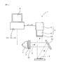
本例においては、図1に示すごとく、光源2、カメラ4、制御部51、画像処理部52、及び判定部53を備えた蛍光検出装置1を用いて、上述の第1励起光照射工程と第1励起時デジタル画像取得工程と第2励起光照射工程と第2励起時デジタル画像取得工程と画像処理工程と検出工程とを行う。
In this example, as shown in FIG. 1, using the
蛍光検出装置1において、光源2は、試料8に対して、特定波長の励起光Xを、フィルタ3を通過させて照射可能である。カメラ4は、試料8の表面をデジタル画像として撮影するよう構成されている。
制御部51、画像処理部52、及び判定部53は、コンピュータ5に構築してあり、光源2及びカメラ4は、コンピュータ5に接続してある。
In the
The control unit 51, the image processing unit 52, and the determination unit 53 are constructed in the
制御部51は、フィルタ3を透過させる励起光Xの波長と強度との少なくとも一方の変更、又は光源2から励起光Xの照射を開始した時点からカメラ4によって撮影する時点までの時間の変更のいずれかを行って、複数種類の励起時デジタル画像D1,D2をカメラ4によって撮影するよう構成してある。
画像処理部52は、複数種類の励起時デジタル画像D1,D2について、それぞれ1つの画素単位ごとの色空間データを求め、複数種類の励起時デジタル画像D1,D2におけるそれぞれ同じ位置にある画素単位の色空間データ同士で照合演算して、画素単位ごとに演算処理データを求めるよう構成してある。
判定部53は、画素単位ごとの演算処理データを、励起光照射時に特定の微生物又はウイルスが励起時に発生する特定蛍光反応について予め求めた演算処理データの規定範囲と照合して、試料8中における特定蛍光反応の有無を検出するよう構成してある。
The control unit 51 changes at least one of the wavelength and intensity of the excitation light X transmitted through the filter 3 or changes the time from when the irradiation of the excitation light X from the
The image processing unit 52 obtains color space data for each pixel unit for the plurality of types of excitation digital images D1 and D2, and each pixel unit at the same position in the plurality of types of excitation digital images D1 and D2. The color space data is collated with each other to obtain operation processing data for each pixel unit.
The determination unit 53 collates the calculation processing data for each pixel unit with the specified range of the calculation processing data obtained in advance for the specific fluorescence reaction generated when the specific microorganism or virus is excited at the time of excitation light irradiation. It is configured to detect the presence or absence of a specific fluorescence reaction.
光源2及び制御部51により、上述の第1励起光照射工程と第2励起光照射工程を行い、カメラ4及び制御部51により、上述の第1デジタル画像取得工程及び第2デジタル画像取得工程を行うことができる。また、画像処理部52及び判定部53により、上述の画像処理工程及び検出工程を行うことができる。
The
以下に、本例の蛍光反応検出装置1及びこれを用いた特定生物成分検出方法につき、図1〜図9を参照して詳説する。
図1は、蛍光反応検出装置1の構成を概略的に示す図である。同図に示すごとく、本例の光源2は、紫外線及び可視光の波長の光を発する紫外線ランプ2によって構成されている。紫外線ランプ2の光通過位置には、特定の波長の光を透過するフィルタ3が配置してあり、フィルタ3を適宜交換することにより、所望の波長、強度の励起光Xを試料8に照射することができる。
Hereinafter, the fluorescence
FIG. 1 is a diagram schematically showing the configuration of the fluorescence
フィルタ3を透過させて試料8へ照射する励起光Xの波長は、UV励起(320〜380nm)、B励起(380〜495nm)又はG励起(495〜570nm)のうちのいずれかに該当する波長である。フィルタ3は、紫外線ランプ2から発せられた光からUV励起の波長の光を透過させるUV励起フィルタ3と、紫外線ランプ2から発せられた光からB励起の波長の光を透過させるB励起フィルタ3と、紫外線ランプ2から発せられた光からG励起の波長の光を透過させるG励起フィルタ3とがある。
また、光源2は、減光フィルタ30を透過させることによって、励起光Xの強度を変更できるよう構成してある。減光フィルタ30は、フィルタ3に対向する位置に配置してある。そして、使用するフィルタ3及び減光フィルタ30を変更することにより、励起光Xの波長及び強度を変更することができる。
また、光源2から試料8へは、ミラー43によって反射させて励起光Xを照射することができる。
The wavelength of the excitation light X that passes through the filter 3 and irradiates the
Further, the
Further, the excitation light X can be irradiated from the
本例のカメラ4は、コンピュータ5によってデジタル処理可能なCMOSカメラ(デジタルカメラ)41に対して、所定の倍率の光学レンズ42を組み合わせて構成されている。カメラ4は、微生物又はウイルスの各検出対象に合わせて、適宜画素数のものを選択し、光学レンズ42の倍率とCMOSカメラ41のデジタルズームによる倍率とによって、1000〜10000倍にデジタル画像を拡大することができる。また、本例においては、カメラ4の光学レンズ42の前には、紫外線を遮断してカメラ4を保護するためのフィルタ44が配置してある。
本例の制御部51は、光源2に対して制御信号を送信して、光源2から光を出射させ、カメラ4に対して制御信号を送信して、カメラ4によって試料8の表面の撮影を行うよう構成されている。
The
The control unit 51 of this example transmits a control signal to the
本例の蛍光反応検出装置1においては、光源2及びフィルタ3から発せられる励起光Xの波長を互いに異ならせて2種類の励起光をそれぞれ試料8に照射する(第1励起光照射工程及び第2励起光照射工程)。そして、カメラ4によって、励起時デジタル画像(第1励起時デジタル画像及び第2励起時デジタル画像)D1,D2を撮影する(第1デジタル画像取得工程及び第2デジタル画像取得工程)。
2種類の励起時デジタル画像D1,D2は、第1励起光照射工程及び第2励起光照射工程における励起光Xの波長を異ならせるとともに、励起光Xの強度又は照射時間(撮影時期)も互いに異ならせて撮影することができる。また、2種類の励起時デジタル画像D1,D2は、第1励起光照射工程及び第2励起光照射工程における励起光Xの強度又は照射時間(撮影時期)のみ互いに異ならせて撮影することもできる。
In the fluorescence
The two types of digital images D1 and D2 at the time of excitation differ in the wavelength of the excitation light X in the first excitation light irradiation step and the second excitation light irradiation step, and the intensity or irradiation time (imaging time) of the excitation light X is also mutually different. You can shoot differently. The two types of excitation digital images D1 and D2 can also be photographed with different intensities or irradiation times (imaging time) of the excitation light X in the first excitation light irradiation step and the second excitation light irradiation step. .
また、2種類の励起時デジタル画像D1,D2のうちの少なくとも一方は、互いに波長が異なる励起光Xを、光源2及びフィルタ3から試料8に対して同時に照射したときのデジタル画像とすることができる。また、この同時に照射する励起光Xは、波長を互いに異ならせるとともに、強度も互いに異ならせて照射することができる。また、この同時に照射する励起光Xは、強度のみ互いに異ならせて照射することもできる。
なお、各励起時デジタル画素D1,D2は、励起光Xを試料8に照射している間に撮影することができ、励起光Xを試料8に照射した直後に撮影することもできる。
In addition, at least one of the two types of excitation digital images D1 and D2 may be a digital image when the
Each of the excitation-time digital pixels D1 and D2 can be photographed while the
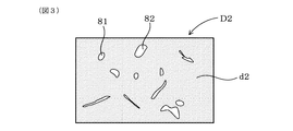
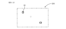
図2には、第1励起時デジタル画像D1を概略的に示し、図3には、第2励起時デジタル画像D2を概略的に示す。また、図4には、第1励起時デジタル画像D1と第2励起時デジタル画像D2とに対して照合演算を行った結果を可視化して、照合画像D3として概略的に示す。 FIG. 2 schematically shows the first excitation digital image D1, and FIG. 3 schematically shows the second excitation digital image D2. In FIG. 4, the result of the collation operation performed on the first excitation digital image D1 and the second excitation digital image D2 is visualized and schematically shown as a collation image D3.
励起光Xの波長は、UV励起、B励起又はG励起のいずれかの波長として、2種類の励起時デジタル画像D1,D2において互いに異ならせることができる。この場合、例えば、図2、図3に示すごとく、2種類の励起時デジタル画像D1,D2のいずれにもゴミ等の検出対象外の異物による蛍光反応82及び微生物等による特定蛍光反応81が撮影されるが、少なくとも特定蛍光反応81については、一方の励起時デジタル画像D1と他方の励起時デジタル画像D2とにおいて、蛍光の強弱により撮影のされ方が異なる場合が想定される。このとき、図4に示すごとく、2種類の励起時デジタル画像D1,D2についての画素単位ごとの色空間データを求めて照合演算を行ったときには、微生物又はウイルスによる特定蛍光反応81を、ゴミ等の異物による蛍光反応82と明確に区別することができる。なお、図2において点線で示した特定蛍光反応81は、図3に示す実線で示した特定蛍光反応81よりも弱いことを意味する。
The wavelength of the excitation light X can be made different from each other in the two types of excitation-time digital images D1 and D2 as the wavelength of UV excitation, B excitation, or G excitation. In this case, for example, as shown in FIGS. 2 and 3, a
また、UV励起、B励起又はG励起のいずれかの波長の励起光Xを用いた場合には、励起光Xの強度、又は撮影時期(光源2から励起光Xの照射を開始した時点からカメラ4によって撮影する時点までの時間)を異ならせて撮影した2種類の励起時デジタル画像D1,D2を用いることもできる。この場合、例えば、図2、図3に示すごとく、異物は、弱い強度の励起光Xの照射又は短い時間の励起光Xの照射によっても蛍光反応82を示す一方、図3に示すごとく、微生物等は、強い強度の励起光Xの照射又は長い時間の励起光Xの照射によってはじめて明確な特定蛍光反応81を示す場合を想定する。このとき、図4に示すごとく、2種類の励起時デジタル画像D1,D2についての画素単位ごとの色空間データを求めて照合演算を行ったときには、異物による蛍光反応82の影響が打ち消されて、微生物等による特定蛍光反応81を明確に検出することができる。この場合は、異物に比べて微生物等が蛍光反応を示す時期が遅い場合に有効である。
Further, when the excitation light X having any wavelength of UV excitation, B excitation, or G excitation is used, the intensity of the excitation light X or the imaging time (from the time when the irradiation of the excitation light X from the
画像処理部52においては、少なくとも上記第1励起時デジタル画像と上記第2励起時デジタル画像について、それぞれ画素単位ごとの色空間データを求めてそれぞれ同じ位置にある画素単位同士で照合演算し、画素単位ごとに演算処理データを求める画像処理工程を行うことができる。ここで求める色空間データは、色の三原色である赤色(R)、緑色(G)、青色(B)の色相データを、所定数の階調における数値で示すものである。本例の色空間データは、カメラ4によって検出した特定の波長の光を、赤色、緑色、青色の各データに分解したものである。赤色、緑色、青色の各データには、それぞれ256階調が割り当てられ、各データ(各原色)は、0〜255の数値によって示される。
また、色空間データには、色の三原色を用いて表す輝度(明るさ)を含めることができる。この輝度Yは、a1〜a3を係数とし、Rを赤色、Gを緑色、Bを青色の各数値としたとき、Y=a1×R+a2×G+a3×Bから求めることができる。係数a1〜a3は、複数の波長の光をカメラ4によって撮影したときの複数のデジタル画像について、赤色、緑色、青色の各数値をY=(a1×X1+a2×X2+a3×X3)/3のX1〜X3にそれぞれ代入して求めることができる。
なお、微生物又はウイルスの検出対象によっては、色空間データは、輝度のデータのみとすることもできる。
The image processing unit 52 obtains color space data for each pixel unit at least for each of the first excitation digital image and the second excitation digital image, and performs a collation operation between the pixel units at the same position. An image processing step for obtaining calculation processing data for each unit can be performed. The color space data obtained here indicates the hue data of red (R), green (G), and blue (B), which are the three primary colors, as numerical values in a predetermined number of gradations. The color space data in this example is obtained by decomposing light of a specific wavelength detected by the
Further, the color space data can include luminance (brightness) expressed using the three primary colors. The luminance Y can be obtained from Y = a1 * R + a2 * G + a3 * B, where a1 to a3 are coefficients, R is red, G is green, and B is blue. The coefficients a1 to a3 are the values of red, green, and blue for a plurality of digital images when light of a plurality of wavelengths is captured by the
Note that depending on the detection target of the microorganism or virus, the color space data may be only luminance data.
画像処理部52において、多数の画素によって示されるデジタル画像における同じ位置にある画素単位同士で行う照合演算は、以下の種々の演算とすることができる。
本例の照合演算は、2種類の励起時デジタル画像D1,D2の色空間データd1,d2における赤色、緑色、青色の各色相同士に対して行う誤差演算又は算術演算である。
In the image processing unit 52, the collation calculation performed between the pixel units at the same position in the digital image indicated by a large number of pixels can be the following various calculations.
The collation operation of this example is an error operation or an arithmetic operation performed on the red, green, and blue hues in the color space data d1, d2 of the two types of excitation digital images D1, D2.
図5には、第1色空間データd1と第2色空間データd2とを、1ドットごとの画素単位において照合する状態を可視化して示す。同図に示すごとく、第1励起時デジタル画像D1についての第1色空間データd1における赤色、緑色、青色の0〜255で示される各数値をR1、G1、B1とし、第2励起時デジタル画像D2についての第2色空間データd2における赤色、緑色、青色の0〜255で示される各数値をR2、G2、B2とする。
誤差演算としては、|R1−R2|(R1−R2の絶対値)、|G1−G2|(G1−G2の絶対値)、|B1−B2|(B1−B2の絶対値)の少なくとも1つとして行うことができる。
FIG. 5 shows a state in which the first color space data d1 and the second color space data d2 are collated in pixel units for each dot. As shown in the figure, the numerical values represented by 0 to 255 of red, green, and blue in the first color space data d1 for the first excitation digital image D1 are R1, G1, and B1, and the second excitation digital image. The numerical values represented by 0 to 255 of red, green, and blue in the second color space data d2 for D2 are R2, G2, and B2.
The error calculation includes at least one of | R1-R2 | (absolute value of R1-R2), | G1-G2 | (absolute value of G1-G2), | B1-B2 | (absolute value of B1-B2). As can be done.
また、算術演算としては、R1+R2、G1+G2、B1+B2の少なくとも1つとして、R1−R2、G1−G2、B1−B2の少なくとも1つとして、R1×R2、G1×G2、B1×B2の少なくとも1つとして、R1/R2、G1/G2、B1/B2の少なくとも1つとして、R2−R1、G2−G1、B2−B1の少なくとも1つとして、又はR2/R1、G2/G1、B2/B1の少なくとも1つとして行うことができる。
また、誤差演算は、第1励起時デジタル画像D1についての第1色空間データd1における輝度の数値をY1とし、第2励起時デジタル画像D2についての第2色空間データd2における輝度の数値をY2として、|Y1−Y2|として行うこともできる。また、算術演算は、Y1+Y2、Y1−Y2、Y1×Y2、Y1/Y2、Y2−Y1、Y2/Y1のいずれかとして行うこともできる。
As arithmetic operations, at least one of R1 + R2, G1 + G2, and B1 + B2, and at least one of R1-R2, G1-G2, and B1-B2, at least one of R1 × R2, G1 × G2, and B1 × B2 As at least one of R1 / R2, G1 / G2, B1 / B2, as at least one of R2-R1, G2-G1, B2-B1, or at least of R2 / R1, G2 / G1, B2 / B1 It can be done as one.
In addition, the error calculation is performed by setting the luminance value in the first color space data d1 for the first excitation digital image D1 to Y1, and the luminance value in the second color space data d2 for the second excitation digital image D2 to Y2. As | Y1-Y2 |. The arithmetic operation can be performed as any one of Y1 + Y2, Y1-Y2, Y1 × Y2, Y1 / Y2, Y2-Y1, and Y2 / Y1.
なお、これらの演算において、R1〜R3、G1〜G3、B1〜B3の各数値が、0未満となる場合は0とし、255超過となる場合には、255とする。また、割算で分母となる数値が0である場合は255とし、割算で分子となる数値が0である場合は0とする。
こうして、画像処理部52において照合演算を行って得られる演算処理データは、0〜255の範囲の数値によって表される。
In these calculations, R1 to R3, G1 to G3, and B1 to B3 are set to 0 when the numerical value is less than 0, and to 255 when the numerical value exceeds 255. Further, when the numerical value that becomes the denominator by division is 0, it is set to 255, and when the numerical value that becomes the numerator by division is 0, it is set to 0.
In this way, the arithmetic processing data obtained by performing the collation operation in the image processing unit 52 is represented by a numerical value in the range of 0 to 255.
判定部53においては、画素単位ごとの演算処理データを、上記特定の微生物又はウイルスが励起時に発生する特定蛍光反応について予め求めた演算処理データの規定範囲と照合して、上記試料中における微生物又はウイルスを検出する検出工程を行うことができる。
判定部53における判定基準である演算処理データの規定範囲は、検出対象とする特定の微生物等に対して、波長と強度との少なくともいずれかが互いに異なる励起光Xを照射したときの複数(2つ)の励起時デジタル画像を撮影し、この励起時デジタル画像中において特定蛍光反応81を映した画素について照合演算を行った結果として求めておく。
また、判定部53における判定基準である演算処理データの規定範囲は、検出対象とする特定の微生物等に対して励起光Xの照射を開始した時点からカメラ4によって撮影する時点までの時間を異ならせて撮影したときの複数(2つ)の励起時デジタル画像において、この励起時デジタル画像中において特定蛍光反応81を映した画素について照合演算を行った結果として求めておくこともできる。
In the determination unit 53, the calculation processing data for each pixel unit is checked against the specified range of the calculation processing data obtained in advance for the specific fluorescence reaction that occurs when the specific microorganism or virus is excited, A detection step of detecting a virus can be performed.
The specified range of the calculation processing data, which is a determination criterion in the determination unit 53, is a plurality (2) when the specific microorganisms or the like to be detected are irradiated with excitation light X having at least one of wavelength and intensity different from each other. Is obtained as a result of performing a collation operation on a pixel in which the
In addition, the prescribed range of the arithmetic processing data which is a determination criterion in the determination unit 53 is different in time from the time when the irradiation of the excitation light X is started to a specific microorganism or the like to be detected to the time when the
演算処理データの規定範囲は、特定の微生物等について特定蛍光反応81を実際に撮影したときの色相、輝度の色空間データに対して、適度の余裕を設けて設定することができる。この際、特定蛍光反応81の撮影を複数回行って、規定範囲の幅を決定することができる。
そして、実際に試料8に対して特定蛍光反応81の検査を行う際には、判定基準である演算処理データの規定範囲を決定する際に使用した励起光Xと同じ条件の励起光Xを試料8に照射する。また、励起光Xの波長又は強度を異ならせた場合には、設定基準時と検出時とで用いる励起光Xの種類を同じにする。
The specified range of the arithmetic processing data can be set with a suitable margin with respect to the color space data of hue and luminance when the
When the specific
図6には、第1色空間データd1と第2色空間データd2とを(図5参照)、1ドットごとの画素単位において照合して得た演算処理データが、規定範囲内にあるか否かの2値化処理を行った結果を可視化して示す。
本例の判定部53は、画素単位ごとの演算処理データのうち、特定の微生物又はウイルスが励起時に発生する特定蛍光反応81について予め求めた演算処理データの規定範囲内にある画素単位を、ヒット画素Hとして求める。そして、ヒット画素Hが並んで形成される形状及び面積が、特定蛍光反応81について予め求めた形状及び面積の規定範囲内にある場合に、試料8中に微生物又はウイルスが存在すると検出する。ヒット画素Hは、各画素単位の演算処理データが、演算処理データの規定範囲内にある場合を1、演算処理データの規定範囲内にない場合を0として、2値化処理を行ったときの1である画素とする。
特定蛍光反応81についての形状及び面積の規定範囲は、検出対象とする特定の微生物等の形状及び面積を実測した値に、適度の余裕を設けて設定することができる。
FIG. 6 shows whether the arithmetic processing data obtained by collating the first color space data d1 and the second color space data d2 (see FIG. 5) in the pixel unit for each dot is within the specified range. The result of the binarization process is visualized and shown.
The determination unit 53 of this example hits a pixel unit within the specified range of the calculation processing data obtained in advance for the
The specified range of the shape and area for the
また、画像処理部52における各画素は、例えば誤差演算として、|R1−R2|、|G1−G2|、|B1−B2|を行った場合には、これらの値の全てが規定範囲内になったときに、ヒット画素Hとすることができる。また、これらの値の1つ又は2つが規定範囲内になったときに、ヒット画素Hとすることもできる。このことは、画像処理部52において、算術演算を行う場合についても同様である。 In addition, for each pixel in the image processing unit 52, when | R1-R2 |, | G1-G2 |, | B1-B2 | When it becomes, it can be set as the hit pixel H. In addition, when one or two of these values are within the specified range, the hit pixel H can be determined. The same applies to the case where the image processing unit 52 performs an arithmetic operation.
判定部53は、特定蛍光反応81が存在すると検出したヒット画素Hが並んで形成される形状を囲む大きさの画素領域を、ヒット領域Aとして特定する。
図4、図7には、ヒット画素Hを囲んでなるヒット領域Aを示す。
本例の判定部53においては、ヒット画素Hを抽出した2値化された演算処理データに対して、ヒット画素Hが並んで形成されたヒット画素形状の最大輪郭に合わせて、デジタル画像のX軸及びY軸に平行な辺を持つ矩形状によって囲む。そして、この矩形状によって囲まれた画素領域がヒット領域Aとして特定され、ヒット領域Aについて、ヒット画素形状が検出対象とする微生物等の特定蛍光反応81の形状と近似するか否かを判定する。
The determination unit 53 specifies a pixel region having a size surrounding a shape in which the hit pixels H detected as having the
4 and 7 show a hit area A surrounding the hit pixel H. FIG.
In the determination unit 53 of this example, the binarized arithmetic processing data obtained by extracting the hit pixels H is matched with the maximum contour of the hit pixel shape formed by arranging the hit pixels H in accordance with the X of the digital image. Surrounded by a rectangle with sides parallel to the axis and the Y axis. Then, the pixel region surrounded by the rectangular shape is specified as the hit region A, and it is determined whether or not the hit pixel shape approximates the shape of the
判定部53においては、矩形状によって囲んだヒット画素形状の面積(ヒット画素Hの数)、重心位置等を検出することができる。また、ヒット画素形状が、微生物等についての特定蛍光反応81の形状及び面積の規定範囲内にある場合には、励起時デジタル画像中の全体におけるヒット画素形状の位置、数等を特定する。特定蛍光反応81の面積の規定範囲は、所定の面積以上であって所定の面積以下の所定の大きさの範囲を有している。ヒット画素形状が大き過ぎても小さ過ぎても、特定蛍光反応81の面積の規定範囲内には入らないことになる。
The determination unit 53 can detect the area (number of hit pixels H) of the hit pixel shape surrounded by the rectangular shape, the center of gravity position, and the like. When the hit pixel shape is within the specified range of the shape and area of the
また、判定部53は、上記ヒット画素形状を検出する以外にも、励起時デジタル画像を構成する全体の面積(画素数)のうち、ヒット画素Hが占める面積(画素数)の割合が所定の割合以上である場合に、試料8中に特定蛍光反応81があると判定することもできる。
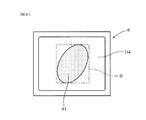
本例の制御部51は、励起光Xを照射していないときの素デジタル画像D4をカメラ4によって撮影し、素デジタル画像D4においてヒット領域Aに相当する画素領域を、コンピュータ5に接続したモニタ6に拡大表示する表示工程を行うよう構成してある。
図8には、素デジタル画像D4について、ヒット領域Aに相当する画素領域Bをモニタ6に拡大表示した状態を概略的に示す。本例においては、素デジタル画像D4において微生物等が存在すると検出した領域を実際に目視により確認することができる。
In addition to detecting the hit pixel shape, the determination unit 53 has a predetermined ratio of the area (number of pixels) occupied by the hit pixel H in the total area (number of pixels) constituting the excitation digital image. When the ratio is equal to or greater than the ratio, it can be determined that the specific
The control unit 51 of this example captures the elementary digital image D4 when the excitation light X is not irradiated by the
FIG. 8 schematically shows a state in which the pixel area B corresponding to the hit area A is enlarged and displayed on the
また、判定部53においては、特定蛍光反応81についての形状及び面積の規定範囲を、複数種類の微生物等について予め設定しておくことができる。そして、判定部53は、ヒット画素形状が並んで形成される形状及び面積が、予め複数種類の微生物等についてそれぞれ求めた形状及び面積の規定範囲のうちのいずれに含まれるかを判定し、試料8中に存在する微生物等の種類を推定することができる。この場合には、微生物等の有無だけでなく、種類も検出することができる。
また、判定部53は、矩形状のヒット領域Aの面積(画素数)に対し、ヒット領域A内において所定の形状を有するヒット画素Hの面積(画素数)の割合によって、微生物等の種類を推定することもできる。
Moreover, in the determination part 53, the prescription | regulation range of the shape and area about the
The determination unit 53 determines the type of microorganism or the like according to the ratio of the area (number of pixels) of the hit pixel H having a predetermined shape in the hit area A to the area (number of pixels) of the rectangular hit area A. It can also be estimated.
次に、蛍光反応検出装置1を用いて微生物等の特定蛍光反応81を検出する手順、即ち特定生物成分の検出方法につき、図9のフローチャートを参照して説明する。
まず、光源2から、所定の波長及び強度を有する第1励起光Xを試料8に照射する(第1励起光照射工程;同図のステップS1)。そして、所定時間経過した後、試料8の表面をカメラ4によって撮影する(第1デジタル画像取得工程;S2)。このとき、試料8においては、第1励起光Xに励起されて種々の蛍光反応が起こり、カメラ4によって所定の可視光線の蛍光を撮影することになる。また、撮影を行った第1励起時デジタル画像D1は、コンピュータ5の画像処理部52(図1参照)に取り込んで記憶する。
Next, a procedure for detecting a
First, the
次いで、光源2から、波長と強度との少なくとも一方が第1励起光Xとは異なる第2励起光Xを試料8に照射する(第2励起光照射工程;S3)。そして、所定時間経過した後、試料8の表面をカメラ4によって撮影する(第2デジタル画像取得工程;S4)。このとき、試料8においては、第2励起光Xに励起されて種々の蛍光反応が起こり、カメラ4によって所定の可視光線の蛍光を撮影することになる。また、撮影を行った第2励起時デジタル画像D2は、コンピュータ5の画像処理部52に取り込んで記憶する。
Next, the
次に、以下のように画像処理工程(S5及びS6)を行う。
具体的には、まず、第1励起時デジタル画像D1における画素単位ごとの第1色空間データd1と、第2励起時デジタル画像D2における画素単位ごとの第2色空間データd2とを求める(S5)。次いで、画素単位ごとの第1色空間データd1と画素単位ごとの第2色空間データd2とに対して、誤差演算又は算術演算の照合演算を行い、画素単位ごとの演算処理データを求める(S6)。
Next, the image processing steps (S5 and S6) are performed as follows.
Specifically, first, first color space data d1 for each pixel unit in the first excitation digital image D1 and second color space data d2 for each pixel unit in the second excitation digital image D2 are obtained (S5). ). Next, an error operation or arithmetic operation collation operation is performed on the first color space data d1 for each pixel unit and the second color space data d2 for each pixel unit to obtain operation processing data for each pixel unit (S6). ).
次に、以下のように検出工程(S7〜S11)を行う。
具体的には、まず、画素単位ごとの演算処理データが、検出対象となる特定の微生物又はウイルスが発生する蛍光(特定蛍光反応81;図3参照)について予め求めた演算処理データの規定範囲内にあるか否かを判定する(S7)。そして、規定範囲内にある画素をヒット画素Hとして抽出する(S8)。一方、全ての画素について規定範囲内にない場合には、試料8中に特定蛍光反応81の検出がなかったものとして終了する(S11)。
ヒット画素Hを抽出し、ヒット画素Hが集まって形成されるヒット画素形状が、予め特定蛍光反応81について求めた形状及び面積の規定範囲内にあるか否かを判定する(S9)。そして、ヒット画素形状が規定範囲内にある場合には、微生物等による特定蛍光反応81があったことを検出する(S10)。一方、ヒット画素形状が規定範囲内にない場合には、試料8中に特定蛍光反応81の検出がなかったものとして終了する(S11)。
Next, a detection process (S7-S11) is performed as follows.
Specifically, first, calculation processing data for each pixel unit is within a specified range of calculation processing data obtained in advance for fluorescence (
The hit pixel H is extracted, and it is determined whether or not the hit pixel shape formed by the gathering of the hit pixels H is within the prescribed range of the shape and area obtained in advance for the specific fluorescence reaction 81 (S9). If the hit pixel shape is within the specified range, it is detected that there is a
本例の特定生物成分検出方法1においては、上記のように、第1照射工程(S1)と、第1デジタル画像取得工程(S2)と、第2励起光照射工程(S3)と、第2デジタル画像取得工程(S4)と、画像処理工程(S5及びS6)と、検出工程(S7〜S11)を少なくとも行う(図9参照)。
第1照射工程においては、試料8に対して、特定の波長、強度、及び照射時間で第1励起光Xを照射する(図1参照)。次いで、第1デジタル画像取得工程においては、第1励起光Xを照射した試料8の表面をカメラ4により撮影し、第1励起時デジタル画像D1を得る(図2参照)。本例においては、試料8中に第1励起光により励起され蛍光を発する成分であるゴミ等の異物が存在するため、第1励起時デジタル画像D1においては、異物が蛍光反応82を示す(図2参照)。また、第1励起時デジタル画像D1においては、第1励起光によって微生物又はウイルスが励起し、これらが弱い特定蛍光反応81を示す。
In the specific biological
In the first irradiation step, the
一方、第2照射工程においては、試料8に対して、第1励起光とは波長、強度、及び照射時間の少なくともいずれかが異なる励起光からなる第2励起光Xを照射する。次いで、第2デジタル画像取得工程においては、第2励起光Xを照射した試料8の表面をカメラ4により撮影し、第2励起時デジタル画像D2を取得する。第1デジタル画像取得工程と同様に、試料8の表面を撮影することにより、試料8の蛍光状態をデジタル画像として取得することができる。第2励起光Xは、波長、強度、及び照射時間の少なくともいずれかが第1励起光とは異なるため、試料8は第1励起光の場合とは異なるパターンで蛍光を発する。本例においては、試料8中に第1励起光だけでなく第2励起光Xによっても蛍光を発する異物が存在するため、第2励起時デジタル画像D2においてもこれらの異物が蛍光反応82を示す(図3参照)。さらに、第2励起時デジタル画像D2においては、第2励起光によって微生物又はウイルスが励起し、これらが強い特定蛍光反応81を示す。
このように1励起時デジタル画像D1と第2励起時デジタル画像D2は、励起光が異なるため異なる蛍光状態を示す(図2及び図3参照)。
On the other hand, in the second irradiation step, the
Thus, the first excitation digital image D1 and the second excitation digital image D2 show different fluorescence states because the excitation light is different (see FIGS. 2 and 3).
画像処理工程においては、第1励起時デジタル画像D1と第2励起時デジタル画像D2について、それぞれ画素単位ごとの色空間データd1,d2を求める。そして、第1励起時デジタル画像D1における画素単位ごとの色空間データd1と、第2励起時デジタル画像D2における画素単位ごとの色空間データd2とに対し、それぞれ同じ位置にある画素単位同士で照合演算し、画素単位ごとに誤差演算又は算術演算を行った演算処理データを求める。 In the image processing step, color space data d1 and d2 for each pixel unit are obtained for the first excitation digital image D1 and the second excitation digital image D2. Then, the color space data d1 for each pixel unit in the first excitation digital image D1 and the color space data d2 for each pixel unit in the second excitation digital image D2 are collated with each other at the same position. Calculation is performed to obtain calculation processing data obtained by performing error calculation or arithmetic calculation for each pixel unit.
次に、検出工程においては、画素単位ごとの演算処理データを、特定の微生物又はウイルスが励起時に発生する特定蛍光反応81について予め求めた演算処理データの規定範囲と照合する。そして、画素単位ごとの演算処理データが、予め特定蛍光反応81について求めた演算処理データの規定範囲内にある場合には、試料8中に微生物等が発する特定蛍光反応81があると判定し、微生物等を検出することができる。
Next, in the detection step, the calculation processing data for each pixel unit is collated with a specified range of calculation processing data obtained in advance for the
ところで、一般的に、試料8には、微生物又はウイルス以外にも、ゴミ等の異物が含まれ、該異物も励起光Xにより蛍光反応82を発生する(図2及び図3参照)。ただし、特定蛍光反応81と、ゴミによる蛍光反応82とは、励起光Xの波長、強度等の条件によって、蛍光の性質が異なる。そこで、本例のように、第1励起時デジタル画像と第2励起時デジタル画像という2種類の励起時デジタル画像D1,D2を撮影した際に、例えば特定蛍光反応81がいずれの励起時デジタル画像D1,D2にも撮影される一方で、いずれかの励起時デジタル画像D1(D2)と他の励起時デジタル画像D2(D1)とにおいて、蛍光(特定蛍光反応81)の強弱により撮影のされ方が異なる場合が想定される(図2及び図3参照)。この場合には、上記照合演算を行うことにより、微生物又はウイルスによる蛍光反応を、ゴミ等の異物による蛍光反応と明確に区別することができる。
したがって、本例の特定生物成分検出方法によれば、試料中における微生物又はウイルスの有無を高い検出精度で、安定して検出することができる。
Incidentally, in general, the
Therefore, according to the specific biological component detection method of this example, the presence or absence of microorganisms or viruses in the sample can be stably detected with high detection accuracy.
(実施例2)
本例は、画像処理工程及び検出工程における処理が、上記実施例1とは異なる例である。
本例の画像処理工程は、第1励起時デジタル画像D1について所定の蛍光反応がある画素領域を特定し、この画素領域についてのみ照合演算を行うことにより、画像処理量を低減させることができるものである。
(Example 2)
This example is an example in which the processes in the image processing step and the detection step are different from those in the first embodiment.
The image processing process of this example can reduce the amount of image processing by specifying a pixel area having a predetermined fluorescence reaction in the first excitation digital image D1 and performing a matching operation only on this pixel area. It is.
本例においても、実施例1と同様に、蛍光検出装置1を用いて、第1励起光照射工程と第1デジタル画像取得工程と第2励起光照射工程と第2デジタル画像取得工程とを行って、2種類の励起光Xを照射したときの2種類の励起時デジタル画像(第1励起時デジタル画像D1,第2励起時デジタル画像D2)をカメラ4によって撮影する(図1、図10、及び図11参照)。
Also in this example, similarly to Example 1, the
本例の画像処理工程においては、蛍光検出装置1の画像処理部52により、第1励起時デジタル画像D1について、それぞれ1つの画素単位ごとの第1色空間データ(基準用色空間データ)d1を求める。そして、画素単位ごとの基準用色空間データd1のうち、所定の規定範囲内にある画素単位の集まりを、仮ヒット画素H’として求め、仮ヒット画素H’を囲む大きさの画素領域を仮ヒット領域A’として特定する。
In the image processing step of this example, the image processing unit 52 of the
図10には、第1励起時デジタル画像D1において、仮ヒット画素H’及び仮ヒット領域A’を特定した状態を可視化して概略的に示す。仮ヒット領域A’は、仮ヒット画素H’が並んで形成されたヒット画素形状の最大輪郭に合わせて、デジタル画像のX軸及びY軸に平行な辺を持つ矩形状によって囲んで形成される。
なお、上記所定の規定範囲は、予め特定蛍光反応81について求めた基準用色空間データd1の規定範囲とすることができる。
FIG. 10 schematically shows a state in which the temporary hit pixel H ′ and the temporary hit area A ′ are identified in the first excitation digital image D1. The temporary hit area A ′ is formed so as to be surrounded by a rectangular shape having sides parallel to the X axis and the Y axis of the digital image in accordance with the maximum outline of the hit pixel shape formed by arranging the temporary hit pixels H ′. .
The predetermined specified range can be the specified range of the reference color space data d1 obtained for the
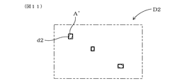
また、画像処理工程においては、第2励起時デジタル画像D2について、仮ヒット領域A’に相当する領域A’のみについて、それぞれ1つの画素単位ごとの第2色空間データ(照合用色空間データ)d2を求める。
図11には、第2励起時デジタル画像D2において、仮ヒット領域A’に相当する領域A’を可視化して概略的に示す。そして、画像処理工程においては、仮ヒット領域A’内の画素単位ごとの基準用色空間データd1と、仮ヒット領域A’に相当する領域内の画素単位ごとの照合用色空間データd2とに対し、それぞれ同じ位置にある画素単位同士で照合演算して、仮ヒット領域A’内の画素単位ごとに演算処理データを求める。
図12には、仮ヒット領域A’内の基準用色空間データd1と、仮ヒット領域A’に相当する領域A’内の照合用色空間データd2とに照合演算を行った結果を、可視化した画像D3として概略的に示す。
In the image processing step, second color space data (collation color space data) for each pixel unit of only the area A ′ corresponding to the temporary hit area A ′ in the second excitation digital image D2. d2 is obtained.
FIG. 11 schematically shows a region A ′ corresponding to the temporary hit region A ′ in the second excitation digital image D2. In the image processing step, the reference color space data d1 for each pixel unit in the temporary hit area A ′ and the matching color space data d2 for each pixel unit in the area corresponding to the temporary hit area A ′ are used. On the other hand, comparison processing is performed between pixel units at the same position, and calculation processing data is obtained for each pixel unit in the temporary hit area A ′.
FIG. 12 visualizes the result of the collation operation performed on the reference color space data d1 in the temporary hit area A ′ and the color space data d2 for collation in the area A ′ corresponding to the temporary hit area A ′. This is schematically shown as an image D3.
基準用色空間データd1と照合用色空間データd2とに行う照合演算は、上記実施例1と同様に、誤差演算又は算術演算とすることができる。
本例の検出工程においては、蛍光検出装置1の判定部53により、仮ヒット領域A’内の画素単位ごとの演算処理データのうち、予め特定蛍光反応81について求めた演算処理データの規定範囲内にある画素単位を、ヒット画素Hとして求める。そして、判定部53は、ヒット画素Hが並んで形成される形状及び面積が、予め特定蛍光反応81について求めた形状及び面積の規定範囲内にある場合に、試料8中に微生物等が存在すると検出することができる。
The collation operation performed on the reference color space data d1 and the collation color space data d2 can be an error operation or an arithmetic operation as in the first embodiment.
In the detection process of this example, the determination unit 53 of the
本例においては、2種類の励起時デジタル画像D1,D2を撮影した際に、例えば、特定蛍光反応81がいずれの励起時デジタル画像にも撮影される一方で、第1励起時デジタル画像D1と第2励起時デジタル画像D2とにおいて、撮影のされ方が異なる場合が想定される。この場合には、上記照合演算をすることにより、微生物又はウイルスによる蛍光反応を、他のゴミ(検出対象外の異物)による蛍光反応と明確に区別することができる。
In this example, when two types of excitation digital images D1 and D2 are photographed, for example, the
本例においては、第2励起時デジタル画像D2について、仮ヒット領域A’に相当する領域のみについて、それぞれ画素単位ごとの照合用色空間データd2を求める。これにより、照合用色空間データd2を求める処理を少なくすることができる。
こうして、デジタル画像の全体の画素領域のうち、特定の限られた画素領域についてのみ、演算処理データを求めことにより、演算処理データを求める処理を少なくすることができる。
本例においても、その他の構成は上記実施例1と同様であり、上記実施例1と同様の作用効果を得ることができる。
In this example, for the second excitation-time digital image D2, the color space data for comparison d2 for each pixel unit is obtained for only the area corresponding to the temporary hit area A ′. As a result, it is possible to reduce the processing for obtaining the matching color space data d2.
In this way, it is possible to reduce the processing for obtaining the arithmetic processing data by obtaining the arithmetic processing data only for a specific limited pixel region in the entire pixel region of the digital image.
Also in this example, other configurations are the same as those of the first embodiment, and the same effects as those of the first embodiment can be obtained.
1 蛍光反応検出装置
2 光源
3 フィルタ
4 カメラ
5 コンピュータ
51 制御部
52 画像処理部
53 判定部
6 モニタ
8 試料
81 特定蛍光反応
X 励起光
D1,D2 励起時デジタル画像
D4 素デジタル画像
d1,d2 色空間データ
H ヒット画素
A ヒット領域
DESCRIPTION OF
Claims (11)
上記試料に対して、特定の波長、強度、及び照射時間で第1励起光を照射する第1励起光照射工程と、
上記第1励起光を照射した試料の表面を撮影し、第1励起時デジタル画像を取得する第1デジタル画像取得工程と、
上記試料に対して、上記第1励起光とは波長、強度、及び照射時間の少なくともいずれかが異なる第2励起光を照射する第2励起光照射工程と、
上記第2励起光を照射した試料の表面を撮影し、第2励起時デジタル画像を取得する第2デジタル画像取得工程と、
少なくとも上記第1励起時デジタル画像と上記第2励起時デジタル画像について、それぞれ画素単位ごとの色空間データを求めてそれぞれ同じ位置にある画素単位同士で照合演算し、画素単位ごとに演算処理データを求める画像処理工程と、
上記画素単位ごとの演算処理データを、上記特定の微生物又はウイルスが励起時に発生する特定蛍光反応について予め求めた演算処理データの規定範囲と照合して、上記試料中における微生物又はウイルスを検出する検出工程とを有することを特徴とする特定生物成分検出方法。 A specific biological component detection method for detecting the specific microorganism or virus by detecting a specific fluorescence reaction generated when a specific microorganism or virus in a sample is excited,
A first excitation light irradiation step of irradiating the sample with the first excitation light at a specific wavelength, intensity, and irradiation time;
A first digital image obtaining step of photographing the surface of the sample irradiated with the first excitation light and obtaining a first excitation digital image;
A second excitation light irradiation step of irradiating the sample with a second excitation light that is different from the first excitation light in at least one of wavelength, intensity, and irradiation time;
A second digital image acquisition step of photographing the surface of the sample irradiated with the second excitation light and acquiring a second excitation digital image;
For at least the first excitation digital image and the second excitation digital image, color space data for each pixel unit is obtained, collation is performed between pixel units at the same position, and calculation processing data is obtained for each pixel unit. The desired image processing process;
Detection for detecting microorganisms or viruses in the sample by comparing the calculation processing data for each pixel unit with a specified range of calculation processing data obtained in advance for the specific fluorescence reaction generated when the specific microorganism or virus is excited. And a specific biological component detection method comprising the steps of:
上記励起光を照射していないときの素デジタル画像を取得し、上記素デジタル画像において上記ヒット領域に相当する画素領域をモニタに拡大表示する表示工程を行うことを特徴とする特定生物成分検出方法。 The specific biological component detection method according to claim 3, wherein a pixel region having a size surrounding a shape in which the hit pixels are formed side by side in the detection step is specified as a hit region,
A specific biological component detection method comprising: performing a display step of acquiring an elementary digital image when the excitation light is not irradiated and enlarging and displaying a pixel region corresponding to the hit region in the elementary digital image on a monitor .
上記試料に対して、特定の波長、強度、及び照射時間で第1励起光を照射する第1励起光照射工程と、
上記第1励起光を照射した試料の表面を撮影し、第1励起時デジタル画像を取得する第1デジタル画像取得工程と、
上記試料に対して、上記第1励起光とは波長、強度、及び照射時間の少なくともいずれかが異なる第2励起光を照射する第2励起光照射工程と、
上記第2励起光を照射した試料の表面を撮影し、第2励起時デジタル画像を取得する第2デジタル画像取得工程と、
上記第1励起時デジタル画像又は上記第2励起時デジタル画像のうちのいずれか一方について、画素単位ごとの色空間データを基準用色空間データとして求め、該基準用色空間データのうち、所定の規定範囲内にある画素単位の集まりを仮ヒット画素として求め、該仮ヒット画素を囲む大きさの画素領域を仮ヒット領域として特定し、かつ上記第1励起時デジタル画像又は上記第2励起時デジタル画像のうちの他方における上記仮ヒット領域に相当する領域のみについて、画素単位ごとの色空間データを照合用色空間データとして求め、上記仮ヒット領域内の上記画素単位ごとの上記基準用色空間データと、上記仮ヒット領域に相当する領域内の上記画素単位ごとの上記照合用色空間データとに対し、それぞれ同じ位置にある画素単位同士で照合演算して、上記仮ヒット領域内の上記画素単位ごとに演算処理データを求める画像処理工程と、
上記仮ヒット領域内の上記画素単位ごとの上記演算処理データを、上記特定の微生物又はウイルスが励起時に発生する特定蛍光反応について予め求めた演算処理データの規定範囲と照合して、上記試料中における微生物又はウイルスを検出する検出工程とを有することを特徴とする特定生物成分検出方法。 A specific biological component detection method for detecting the specific microorganism or virus by detecting a specific fluorescence reaction generated when a specific microorganism or virus in a sample is excited,
A first excitation light irradiation step of irradiating the sample with the first excitation light at a specific wavelength, intensity, and irradiation time;
A first digital image obtaining step of photographing the surface of the sample irradiated with the first excitation light and obtaining a first excitation digital image;
A second excitation light irradiation step of irradiating the sample with a second excitation light that is different from the first excitation light in at least one of wavelength, intensity, and irradiation time;
A second digital image acquisition step of photographing the surface of the sample irradiated with the second excitation light and acquiring a second excitation digital image;
For either one of the first excitation time digital image or the second excitation time digital image, color space data for each pixel unit is obtained as reference color space data, and among the reference color space data, a predetermined color space data is determined. A group of pixel units within a specified range is obtained as a temporary hit pixel, a pixel area having a size surrounding the temporary hit pixel is specified as a temporary hit area, and the first excitation digital image or the second excitation digital For only the region corresponding to the temporary hit region in the other of the images, color space data for each pixel unit is obtained as color space data for comparison, and the reference color space data for each pixel unit in the temporary hit region And the matching color space data for each pixel unit in the region corresponding to the temporary hit region, the pixel units at the same position And disjunction, and an image processing step of determining the operation processing data for each of the pixel unit of the temporary hit region,
The calculation processing data for each pixel unit in the temporary hit region is compared with a specified range of calculation processing data obtained in advance for the specific fluorescence reaction that occurs when the specific microorganism or virus is excited, in the sample. And a specific biological component detection method comprising a detection step of detecting a microorganism or a virus.
上記励起光を照射していないときの素デジタル画像を取得し、上記素デジタル画像において上記ヒット領域に相当する画素領域をモニタに拡大表示する表示工程を行うことを特徴とする特定生物成分検出方法。 The specific biological component detection method according to claim 7, wherein a pixel region having a size surrounding a shape in which the hit pixels are formed side by side in the detection step is specified as a hit region,
A specific biological component detection method comprising: performing a display step of acquiring an elementary digital image when the excitation light is not irradiated and enlarging and displaying a pixel region corresponding to the hit region in the elementary digital image on a monitor .
上記画像処理工程における上記照合演算は、上記色相及び輝度のうち少なくとも1つ同士に対して行う誤差演算又は算術演算であることを特徴とする特定生物成分検出方法。 The specific biological component detection method according to any one of claims 1 to 8, wherein the color space data is at least one of red, green, blue hue, and luminance,
The specific biological component detection method, wherein the collation operation in the image processing step is an error operation or an arithmetic operation performed on at least one of the hue and luminance.
Priority Applications (1)
| Application Number | Priority Date | Filing Date | Title |
|---|---|---|---|
| JP2011030681A JP2012168084A (en) | 2011-02-16 | 2011-02-16 | Method for detecting specific microbial components |
Applications Claiming Priority (1)
| Application Number | Priority Date | Filing Date | Title |
|---|---|---|---|
| JP2011030681A JP2012168084A (en) | 2011-02-16 | 2011-02-16 | Method for detecting specific microbial components |
Publications (1)
| Publication Number | Publication Date |
|---|---|
| JP2012168084A true JP2012168084A (en) | 2012-09-06 |
Family
ID=46972386
Family Applications (1)
| Application Number | Title | Priority Date | Filing Date |
|---|---|---|---|
| JP2011030681A Withdrawn JP2012168084A (en) | 2011-02-16 | 2011-02-16 | Method for detecting specific microbial components |
Country Status (1)
| Country | Link |
|---|---|
| JP (1) | JP2012168084A (en) |
-
2011
- 2011-02-16 JP JP2011030681A patent/JP2012168084A/en not_active Withdrawn
Similar Documents
| Publication | Publication Date | Title |
|---|---|---|
| US9817016B1 (en) | Low cost optical high speed discrete measurement system | |
| US20180116520A1 (en) | Imaging apparatus | |
| US20060291706A1 (en) | Method of extracting intensity data from digitized image | |
| JP6765036B2 (en) | Visual inspection equipment and visual inspection method | |
| CN112166314A (en) | Fluorescence observation apparatus and fluorescence observation method | |
| CN108692815B (en) | Multispectral imaging using longitudinal chromatic aberration | |
| WO2020036121A1 (en) | Endoscope system | |
| WO2015111349A1 (en) | Multicolor-fluorescence-image analysis device | |
| WO2020008834A1 (en) | Image processing device, method, and endoscopic system | |
| JP4029983B2 (en) | Microorganism inspection apparatus and inspection method | |
| JP7209469B2 (en) | Microscopy system and method for quantifying fluorescence | |
| JP7312873B2 (en) | Method and apparatus for determining properties of objects | |
| JP7223840B2 (en) | Systems, methods, and apparatus for autonomous diagnostic verification of optical components of vision-based inspection systems | |
| US9558551B2 (en) | Image measurement apparatus and image measurement method for determining a proportion of positive cell nuclei among cell nuclei included in a pathologic examination specimen | |
| JP5953195B2 (en) | Imaging analysis apparatus, control method thereof, and program for imaging analysis apparatus | |
| JP2012168085A (en) | Method for detecting specific microbial components | |
| WO2018008136A1 (en) | Image processing device and operation method for image processing device | |
| US10866400B2 (en) | Data recovery device, microscope system, and data recovery method | |
| JP2012168088A (en) | Fluorescent reaction detector | |
| JP2012003004A (en) | Image acquisition device and image acquisition method | |
| JP2012168086A (en) | Fluorescent reaction detector | |
| JP2012168084A (en) | Method for detecting specific microbial components | |
| JP2023089967A (en) | Fluorescence microscope system and method | |
| JP2012193988A (en) | Fluorescence reaction detector | |
| JP7291314B2 (en) | Medical imaging device and method of operating a medical imaging device |
Legal Events
| Date | Code | Title | Description |
|---|---|---|---|
| A300 | Withdrawal of application because of no request for examination |
Free format text: JAPANESE INTERMEDIATE CODE: A300 Effective date: 20140513 |