JP2012167768A - Electrically fusing joint for covered polyethylene tube and polyethylene tube channel using the same - Google Patents
Electrically fusing joint for covered polyethylene tube and polyethylene tube channel using the same Download PDFInfo
- Publication number
- JP2012167768A JP2012167768A JP2011030406A JP2011030406A JP2012167768A JP 2012167768 A JP2012167768 A JP 2012167768A JP 2011030406 A JP2011030406 A JP 2011030406A JP 2011030406 A JP2011030406 A JP 2011030406A JP 2012167768 A JP2012167768 A JP 2012167768A
- Authority
- JP
- Japan
- Prior art keywords
- joint
- coated polyethylene
- receiving port
- pipe
- joint body
- Prior art date
- Legal status (The legal status is an assumption and is not a legal conclusion. Google has not performed a legal analysis and makes no representation as to the accuracy of the status listed.)
- Granted
Links
Images


Classifications
-
- B—PERFORMING OPERATIONS; TRANSPORTING
- B29—WORKING OF PLASTICS; WORKING OF SUBSTANCES IN A PLASTIC STATE IN GENERAL
- B29C—SHAPING OR JOINING OF PLASTICS; SHAPING OF MATERIAL IN A PLASTIC STATE, NOT OTHERWISE PROVIDED FOR; AFTER-TREATMENT OF THE SHAPED PRODUCTS, e.g. REPAIRING
- B29C66/00—General aspects of processes or apparatus for joining preformed parts
- B29C66/50—General aspects of joining tubular articles; General aspects of joining long products, i.e. bars or profiled elements; General aspects of joining single elements to tubular articles, hollow articles or bars; General aspects of joining several hollow-preforms to form hollow or tubular articles
- B29C66/51—Joining tubular articles, profiled elements or bars; Joining single elements to tubular articles, hollow articles or bars; Joining several hollow-preforms to form hollow or tubular articles
- B29C66/52—Joining tubular articles, bars or profiled elements
- B29C66/522—Joining tubular articles
- B29C66/5221—Joining tubular articles for forming coaxial connections, i.e. the tubular articles to be joined forming a zero angle relative to each other
-
- B—PERFORMING OPERATIONS; TRANSPORTING
- B29—WORKING OF PLASTICS; WORKING OF SUBSTANCES IN A PLASTIC STATE IN GENERAL
- B29C—SHAPING OR JOINING OF PLASTICS; SHAPING OF MATERIAL IN A PLASTIC STATE, NOT OTHERWISE PROVIDED FOR; AFTER-TREATMENT OF THE SHAPED PRODUCTS, e.g. REPAIRING
- B29C65/00—Joining or sealing of preformed parts, e.g. welding of plastics materials; Apparatus therefor
- B29C65/02—Joining or sealing of preformed parts, e.g. welding of plastics materials; Apparatus therefor by heating, with or without pressure
- B29C65/34—Joining or sealing of preformed parts, e.g. welding of plastics materials; Apparatus therefor by heating, with or without pressure using heated elements which remain in the joint, e.g. "verlorenes Schweisselement"
- B29C65/3404—Joining or sealing of preformed parts, e.g. welding of plastics materials; Apparatus therefor by heating, with or without pressure using heated elements which remain in the joint, e.g. "verlorenes Schweisselement" characterised by the type of heated elements which remain in the joint
- B29C65/342—Joining or sealing of preformed parts, e.g. welding of plastics materials; Apparatus therefor by heating, with or without pressure using heated elements which remain in the joint, e.g. "verlorenes Schweisselement" characterised by the type of heated elements which remain in the joint comprising at least a single wire, e.g. in the form of a winding
- B29C65/3432—Joining or sealing of preformed parts, e.g. welding of plastics materials; Apparatus therefor by heating, with or without pressure using heated elements which remain in the joint, e.g. "verlorenes Schweisselement" characterised by the type of heated elements which remain in the joint comprising at least a single wire, e.g. in the form of a winding comprising several wires, e.g. in the form of several independent windings
-
- B—PERFORMING OPERATIONS; TRANSPORTING
- B29—WORKING OF PLASTICS; WORKING OF SUBSTANCES IN A PLASTIC STATE IN GENERAL
- B29C—SHAPING OR JOINING OF PLASTICS; SHAPING OF MATERIAL IN A PLASTIC STATE, NOT OTHERWISE PROVIDED FOR; AFTER-TREATMENT OF THE SHAPED PRODUCTS, e.g. REPAIRING
- B29C65/00—Joining or sealing of preformed parts, e.g. welding of plastics materials; Apparatus therefor
- B29C65/66—Joining or sealing of preformed parts, e.g. welding of plastics materials; Apparatus therefor by liberation of internal stresses, e.g. shrinking of one of the parts to be joined
- B29C65/68—Joining or sealing of preformed parts, e.g. welding of plastics materials; Apparatus therefor by liberation of internal stresses, e.g. shrinking of one of the parts to be joined using auxiliary shrinkable elements
-
- B—PERFORMING OPERATIONS; TRANSPORTING
- B29—WORKING OF PLASTICS; WORKING OF SUBSTANCES IN A PLASTIC STATE IN GENERAL
- B29C—SHAPING OR JOINING OF PLASTICS; SHAPING OF MATERIAL IN A PLASTIC STATE, NOT OTHERWISE PROVIDED FOR; AFTER-TREATMENT OF THE SHAPED PRODUCTS, e.g. REPAIRING
- B29C66/00—General aspects of processes or apparatus for joining preformed parts
- B29C66/01—General aspects dealing with the joint area or with the area to be joined
- B29C66/05—Particular design of joint configurations
- B29C66/10—Particular design of joint configurations particular design of the joint cross-sections
- B29C66/11—Joint cross-sections comprising a single joint-segment, i.e. one of the parts to be joined comprising a single joint-segment in the joint cross-section
- B29C66/112—Single lapped joints
- B29C66/1122—Single lap to lap joints, i.e. overlap joints
-
- B—PERFORMING OPERATIONS; TRANSPORTING
- B29—WORKING OF PLASTICS; WORKING OF SUBSTANCES IN A PLASTIC STATE IN GENERAL
- B29C—SHAPING OR JOINING OF PLASTICS; SHAPING OF MATERIAL IN A PLASTIC STATE, NOT OTHERWISE PROVIDED FOR; AFTER-TREATMENT OF THE SHAPED PRODUCTS, e.g. REPAIRING
- B29C66/00—General aspects of processes or apparatus for joining preformed parts
- B29C66/01—General aspects dealing with the joint area or with the area to be joined
- B29C66/05—Particular design of joint configurations
- B29C66/10—Particular design of joint configurations particular design of the joint cross-sections
- B29C66/12—Joint cross-sections combining only two joint-segments; Tongue and groove joints; Tenon and mortise joints; Stepped joint cross-sections
- B29C66/122—Joint cross-sections combining only two joint-segments, i.e. one of the parts to be joined comprising only two joint-segments in the joint cross-section
- B29C66/1222—Joint cross-sections combining only two joint-segments, i.e. one of the parts to be joined comprising only two joint-segments in the joint cross-section comprising at least a lapped joint-segment
-
- B—PERFORMING OPERATIONS; TRANSPORTING
- B29—WORKING OF PLASTICS; WORKING OF SUBSTANCES IN A PLASTIC STATE IN GENERAL
- B29C—SHAPING OR JOINING OF PLASTICS; SHAPING OF MATERIAL IN A PLASTIC STATE, NOT OTHERWISE PROVIDED FOR; AFTER-TREATMENT OF THE SHAPED PRODUCTS, e.g. REPAIRING
- B29C66/00—General aspects of processes or apparatus for joining preformed parts
- B29C66/01—General aspects dealing with the joint area or with the area to be joined
- B29C66/05—Particular design of joint configurations
- B29C66/10—Particular design of joint configurations particular design of the joint cross-sections
- B29C66/12—Joint cross-sections combining only two joint-segments; Tongue and groove joints; Tenon and mortise joints; Stepped joint cross-sections
- B29C66/122—Joint cross-sections combining only two joint-segments, i.e. one of the parts to be joined comprising only two joint-segments in the joint cross-section
- B29C66/1224—Joint cross-sections combining only two joint-segments, i.e. one of the parts to be joined comprising only two joint-segments in the joint cross-section comprising at least a butt joint-segment
-
- B—PERFORMING OPERATIONS; TRANSPORTING
- B29—WORKING OF PLASTICS; WORKING OF SUBSTANCES IN A PLASTIC STATE IN GENERAL
- B29C—SHAPING OR JOINING OF PLASTICS; SHAPING OF MATERIAL IN A PLASTIC STATE, NOT OTHERWISE PROVIDED FOR; AFTER-TREATMENT OF THE SHAPED PRODUCTS, e.g. REPAIRING
- B29C66/00—General aspects of processes or apparatus for joining preformed parts
- B29C66/50—General aspects of joining tubular articles; General aspects of joining long products, i.e. bars or profiled elements; General aspects of joining single elements to tubular articles, hollow articles or bars; General aspects of joining several hollow-preforms to form hollow or tubular articles
- B29C66/51—Joining tubular articles, profiled elements or bars; Joining single elements to tubular articles, hollow articles or bars; Joining several hollow-preforms to form hollow or tubular articles
- B29C66/52—Joining tubular articles, bars or profiled elements
- B29C66/522—Joining tubular articles
- B29C66/5223—Joining tubular articles for forming corner connections or elbows, e.g. for making V-shaped pieces
-
- B—PERFORMING OPERATIONS; TRANSPORTING
- B29—WORKING OF PLASTICS; WORKING OF SUBSTANCES IN A PLASTIC STATE IN GENERAL
- B29C—SHAPING OR JOINING OF PLASTICS; SHAPING OF MATERIAL IN A PLASTIC STATE, NOT OTHERWISE PROVIDED FOR; AFTER-TREATMENT OF THE SHAPED PRODUCTS, e.g. REPAIRING
- B29C66/00—General aspects of processes or apparatus for joining preformed parts
- B29C66/50—General aspects of joining tubular articles; General aspects of joining long products, i.e. bars or profiled elements; General aspects of joining single elements to tubular articles, hollow articles or bars; General aspects of joining several hollow-preforms to form hollow or tubular articles
- B29C66/51—Joining tubular articles, profiled elements or bars; Joining single elements to tubular articles, hollow articles or bars; Joining several hollow-preforms to form hollow or tubular articles
- B29C66/52—Joining tubular articles, bars or profiled elements
- B29C66/522—Joining tubular articles
- B29C66/5229—Joining tubular articles involving the use of a socket
- B29C66/52291—Joining tubular articles involving the use of a socket said socket comprising a stop
- B29C66/52292—Joining tubular articles involving the use of a socket said socket comprising a stop said stop being internal
-
- B—PERFORMING OPERATIONS; TRANSPORTING
- B29—WORKING OF PLASTICS; WORKING OF SUBSTANCES IN A PLASTIC STATE IN GENERAL
- B29C—SHAPING OR JOINING OF PLASTICS; SHAPING OF MATERIAL IN A PLASTIC STATE, NOT OTHERWISE PROVIDED FOR; AFTER-TREATMENT OF THE SHAPED PRODUCTS, e.g. REPAIRING
- B29C66/00—General aspects of processes or apparatus for joining preformed parts
- B29C66/50—General aspects of joining tubular articles; General aspects of joining long products, i.e. bars or profiled elements; General aspects of joining single elements to tubular articles, hollow articles or bars; General aspects of joining several hollow-preforms to form hollow or tubular articles
- B29C66/51—Joining tubular articles, profiled elements or bars; Joining single elements to tubular articles, hollow articles or bars; Joining several hollow-preforms to form hollow or tubular articles
- B29C66/52—Joining tubular articles, bars or profiled elements
- B29C66/522—Joining tubular articles
- B29C66/5229—Joining tubular articles involving the use of a socket
- B29C66/52298—Joining tubular articles involving the use of a socket said socket being composed by several elements
-
- B—PERFORMING OPERATIONS; TRANSPORTING
- B29—WORKING OF PLASTICS; WORKING OF SUBSTANCES IN A PLASTIC STATE IN GENERAL
- B29C—SHAPING OR JOINING OF PLASTICS; SHAPING OF MATERIAL IN A PLASTIC STATE, NOT OTHERWISE PROVIDED FOR; AFTER-TREATMENT OF THE SHAPED PRODUCTS, e.g. REPAIRING
- B29C66/00—General aspects of processes or apparatus for joining preformed parts
- B29C66/70—General aspects of processes or apparatus for joining preformed parts characterised by the composition, physical properties or the structure of the material of the parts to be joined; Joining with non-plastics material
- B29C66/71—General aspects of processes or apparatus for joining preformed parts characterised by the composition, physical properties or the structure of the material of the parts to be joined; Joining with non-plastics material characterised by the composition of the plastics material of the parts to be joined
-
- B—PERFORMING OPERATIONS; TRANSPORTING
- B29—WORKING OF PLASTICS; WORKING OF SUBSTANCES IN A PLASTIC STATE IN GENERAL
- B29C—SHAPING OR JOINING OF PLASTICS; SHAPING OF MATERIAL IN A PLASTIC STATE, NOT OTHERWISE PROVIDED FOR; AFTER-TREATMENT OF THE SHAPED PRODUCTS, e.g. REPAIRING
- B29C66/00—General aspects of processes or apparatus for joining preformed parts
- B29C66/70—General aspects of processes or apparatus for joining preformed parts characterised by the composition, physical properties or the structure of the material of the parts to be joined; Joining with non-plastics material
- B29C66/72—General aspects of processes or apparatus for joining preformed parts characterised by the composition, physical properties or the structure of the material of the parts to be joined; Joining with non-plastics material characterised by the structure of the material of the parts to be joined
- B29C66/723—General aspects of processes or apparatus for joining preformed parts characterised by the composition, physical properties or the structure of the material of the parts to be joined; Joining with non-plastics material characterised by the structure of the material of the parts to be joined being multi-layered
-
- B—PERFORMING OPERATIONS; TRANSPORTING
- B29—WORKING OF PLASTICS; WORKING OF SUBSTANCES IN A PLASTIC STATE IN GENERAL
- B29C—SHAPING OR JOINING OF PLASTICS; SHAPING OF MATERIAL IN A PLASTIC STATE, NOT OTHERWISE PROVIDED FOR; AFTER-TREATMENT OF THE SHAPED PRODUCTS, e.g. REPAIRING
- B29C66/00—General aspects of processes or apparatus for joining preformed parts
- B29C66/90—Measuring or controlling the joining process
- B29C66/97—Checking completion of joining or correct joining by using indications on at least one of the joined parts
- B29C66/976—Checking completion of joining or correct joining by using indications on at least one of the joined parts by the use of an indicator pin, e.g. being integral with one of the parts to be joined
Abstract
Description
この発明は、被覆ポリエチレン管用電気融着継手およびそれを用いた被覆ポリエチレン管路に関し、特にたとえば、被覆ポリエチレン管どうしを接続するために用いられる、被覆ポリエチレン管用電気融着継手およびそれを用いた被覆ポリエチレン管路に関する。 The present invention relates to an electric fusion joint for coated polyethylene pipe and a coated polyethylene pipe using the same, and more particularly to an electric fusion joint for coated polyethylene pipe used for connecting, for example, coated polyethylene pipes, and a coating using the same. It relates to polyethylene pipelines.
従来、ポリエチレン管の損傷や紫外線等による劣化を防止するために、ポリエチレン管の外周面に被覆層を施す技術が公知である。このようにして形成された被覆ポリエチレン管どうしを継手を用いて接続する場合には、ポリエチレン管と同様に、継手の外表面にも被覆層を施すことが求められる。 Conventionally, a technique for applying a coating layer to the outer peripheral surface of a polyethylene pipe in order to prevent damage to the polyethylene pipe or deterioration due to ultraviolet rays or the like is known. When connecting the coated polyethylene pipes formed in this way using a joint, it is required to coat the outer surface of the joint as well as the polyethylene pipe.
たとえば、特許文献1の配管接続構造では、電気融着継手の継手本体の外周面がカバー部材によって覆われている。カバー部材は、互いに半円筒形状をなす第1カバー部と第2カバーとを結合させることによって形成される。各カバー部の端には、軸線方向へ張り出す鍔部分が設けられ、この鍔部分には、管部材との融着のための電熱線が埋め込まれている。そして、第1カバー部と第2カバー部とで継手本体を挟み込んで、カバー部どうしを機械的に結合させるとともに、各カバー部の鍔部分(の電熱線)を管部材に融着させることによって、カバー部材を継手本体に固定的に装着する。
しかしながら、特許文献1では、継手本体を管部材に融着させるのみならず、各カバー部の鍔部分を管部材に融着させるようにしているので、2度の通電(融着)作業が必要であり、その作業に手間や時間がかかってしまう。つまり、作業性に難点がある。 However, in Patent Document 1, not only the joint body is fused to the pipe member, but also the flange portion of each cover portion is fused to the pipe member, so two energization (fusion) operations are required. And it takes time and effort for the work. That is, there is a difficulty in workability.
また、これを回避するために、各カバー部の鍔部分を管部材に融着させずに、カバー部どうしの機械的な結合のみで、継手本体にカバー部材を装着することも考えられるが、そうすると、カバー部材が外部からの衝撃に対して非常に弱く、カバー部材が外れて耐候性の劣化につながる。 In order to avoid this, it is also conceivable to attach the cover member to the joint body only by mechanical coupling of the cover portions without fusing the flange portion of each cover portion to the pipe member. If it does so, a cover member will be very weak with respect to the impact from the outside, a cover member will remove | deviate and it will lead to deterioration of a weather resistance.
それゆえに、この発明の主たる目的は、新規な、被覆ポリエチレン管用電気融着継手およびそれを用いた被覆ポリエチレン管路を提供することである。 Therefore, a main object of the present invention is to provide a novel electrofusion joint for a coated polyethylene pipe and a coated polyethylene pipe using the same.
この発明の他の目的は、作業性に優れ、しかも被覆層の脱落などが生じにくい、被覆ポリエチレン管用電気融着継手およびそれを用いた被覆ポリエチレン管路を提供することである。 Another object of the present invention is to provide an electrofused joint for a coated polyethylene pipe and a coated polyethylene pipe using the same, which are excellent in workability and hardly cause the coating layer to fall off.
本発明は、上記の課題を解決するために、以下の構成を採用した。なお、括弧内の参照符号および補足説明などは、本発明の理解を助けるために後述する実施の形態との対応関係を示したものであって、本発明を何ら限定するものではない。 The present invention employs the following configuration in order to solve the above problems. Note that reference numerals in parentheses, supplementary explanations, and the like indicate correspondence relationships with embodiments described later to help understanding of the present invention, and do not limit the present invention in any way.
第1の発明は、被覆ポリエチレン管どうしを接続するために用いられる被覆ポリエチレン管用電気融着継手であって、ポリエチレンからなり、被覆ポリエチレン管の管端を受容する受口を有する継手本体、および継手本体の表面に被せられ、受口の開口端から軸方向に突出するかつ内径が被覆ポリエチレン管の外径より大きい鍔部を有する熱収縮チューブを備える、被覆ポリエチレン管用電気融着継手である。 A first invention is an electric fusion joint for coated polyethylene pipes used for connecting coated polyethylene pipes, the joint main body having a receiving port made of polyethylene and receiving a pipe end of the coated polyethylene pipe, and the joint An electrofusion joint for a coated polyethylene pipe, comprising a heat-shrinkable tube that covers the surface of the main body, protrudes in the axial direction from the open end of the receiving port, and has a flange having an inner diameter larger than the outer diameter of the coated polyethylene pipe.
第1の発明では、電気融着継手(10)は、継手本体(12)、および継手本体の表面に被せられる熱収縮チューブ(14)を備えており、被覆ポリエチレン管(100)どうしを接続するために用いられる。たとえば、継手本体の両端開口部は、被覆ポリエチレン管の管端を受容する受口(16)となる。そして、たとえば、接合に供する部分の外層(104)を除去して融着面(106)を得た被覆ポリエチレン管の管端を受口に挿入し、電熱線(18)に電流を流すことによって、受口の内面と被覆ポリエチレン管の融着面との電気融着接合が行われる。また、熱収縮チューブは、加熱処理を施すことによって収縮するチューブであり、継手本体の表面に紫外線等による劣化を防止するための被覆層を形成する。熱収縮チューブの両端部には、継手本体の受口の開口端からさらに軸方向に突き出す鍔部(32)が形成されており、この鍔部が、継手本体の受口が被覆ポリエチレン管の管端を受容したときに、受口の開口端と被覆ポリエチレン管の外層との間にできる隙間を覆う。 In the first invention, the electrofusion joint (10) includes a joint body (12) and a heat-shrinkable tube (14) that covers the surface of the joint body, and connects the coated polyethylene pipes (100) to each other. Used for. For example, both end openings of the joint body serve as receptacles (16) for receiving the pipe ends of the coated polyethylene pipe. Then, for example, by removing the outer layer (104) of the portion to be joined and obtaining the fused surface (106), the tube end of the coated polyethylene pipe is inserted into the receiving port, and a current is passed through the heating wire (18). Then, electrofusion bonding is performed between the inner surface of the receiving port and the fused surface of the coated polyethylene pipe. The heat-shrinkable tube is a tube that shrinks when subjected to heat treatment, and forms a coating layer for preventing deterioration due to ultraviolet rays or the like on the surface of the joint body. At both ends of the heat-shrinkable tube, a flange portion (32) is formed that protrudes further in the axial direction from the open end of the joint body receiving port. When the end is received, a gap formed between the open end of the receiving port and the outer layer of the coated polyethylene pipe is covered.
第1の発明によれば、継手本体の受口と被覆ポリエチレン管の融着面とを電気融着接合するだけで、管路全体に耐候性を付与することができるので、作業性に優れる。 According to the first aspect of the present invention, weather resistance can be imparted to the entire pipe line simply by electrical fusion bonding the receiving port of the joint body and the fused surface of the coated polyethylene pipe, resulting in excellent workability.
しかも、熱収縮チューブを継手本体の表面に密着させることによって被覆層を形成したため、被覆層が外部からの衝撃に対して強く、被覆層の脱落が生じにくいので、それに起因する耐候性の劣化の可能性が抑制される。 Moreover, since the coating layer is formed by closely attaching the heat-shrinkable tube to the surface of the joint body, the coating layer is resistant to external impacts, and the coating layer is unlikely to fall off. The possibility is suppressed.
第2の発明は、第1の発明に従属し、継手本体は、受口の内面に埋設される電熱線、受口の外面に突出して設けられるかつ電熱線に通電するための端子部、および受口の外面に突出して設けられるかつ受口の内面と被覆ポリエチレン管の管端とが融着したことを示すためのインジケータを有し、熱収縮チューブには、端子部およびインジケータを挿通させるための挿通孔が形成される。 A second invention is dependent on the first invention, and the joint main body is a heating wire embedded in the inner surface of the receiving port, a terminal portion that protrudes from the outer surface of the receiving port and energizes the heating wire, and Protruding to the outer surface of the receiving port and having an indicator for indicating that the inner surface of the receiving port and the tube end of the coated polyethylene tube are fused, and for inserting the terminal portion and the indicator through the heat shrinkable tube The insertion hole is formed.
第2の発明では、継手本体(12)の受口(16)の内面には、電熱線(18)が埋め込まれている。また、受口の外面には、電熱線に通電するための端子部(22)、および受口の内面と被覆ポリエチレン管(100)の融着面(106)とが融着したことを示すためのインジケータ(24)が突出して形成されている。さらに、熱収縮チューブ(14)には、厚み方向に貫通する挿通孔(28,30)が形成され、そのうちの或る挿通孔(28)には、受口の外面から突き出している端子部が挿通され、他の挿通孔(30)には、受口の内面と被覆ポリエチレン管の融着面とが正しく融着されたときに上昇したインジケータが挿通される。 In the second invention, the heating wire (18) is embedded in the inner surface of the receiving port (16) of the joint body (12). Moreover, in order to show that the terminal part (22) for energizing a heating wire and the inner surface of the receptacle and the fusion surface (106) of the coated polyethylene pipe (100) were fused to the outer surface of the receptacle. The indicator (24) is projected and formed. Further, the heat-shrinkable tube (14) is formed with insertion holes (28, 30) penetrating in the thickness direction, and certain of the insertion holes (28) have terminal portions protruding from the outer surface of the receiving port. The indicator that has been raised when the inner surface of the receiving port and the fused surface of the coated polyethylene pipe are correctly fused is inserted into the other insertion hole (30).
第3の発明は、第1または2の発明に従属し、継手本体を収縮前の熱収縮チューブ内に収容し、そして受口に収縮防止コアを挿入した状態で加熱することによって、熱収縮チューブを収縮させて継手本体の表面に被せた。 A third invention is dependent on the first or second invention, wherein the joint main body is accommodated in the heat-shrinkable tube before shrinkage, and is heated in a state where the shrinkage-preventing core is inserted into the receiving port. Was shrunk and placed on the surface of the joint body.
第3の発明では、熱収縮チューブ(14)を継手本体(12)の表面に被せるときに、収縮前の熱収縮チューブ内に継手本体を収容し、その継手本体の受口(16)に収縮防止コア(40)を挿入する。そして、それらをたとえば熱収縮チューブが収縮する所定の温度に加熱しておいたギヤーオーブン等の加熱炉の中に入れて、所定の時間加熱することにより、熱収縮チューブを収縮させて継手本体の外表面に密着させる。このとき、継手本体の受口は、加熱炉の加熱によって収縮しようとするが、内面側から収縮防止コアに押さえられることにより、形状および寸法が保持される。 In the third invention, when the heat-shrinkable tube (14) is put on the surface of the joint body (12), the joint body is accommodated in the heat-shrinkable tube before shrinkage, and the joint body receives the joint (16). Insert the prevention core (40). Then, they are put in a heating furnace such as a gear oven that has been heated to a predetermined temperature at which the heat-shrinkable tube contracts, and heated for a predetermined time, thereby contracting the heat-shrinkable tube and Adhere to the outer surface. At this time, the receiving port of the joint body tends to shrink by heating in the heating furnace, but the shape and dimensions are maintained by being pressed by the shrinkage preventing core from the inner surface side.
第3の発明によれば、継手本体の受口の形状の変形を抑制することができるので、電気融着継手と被覆ポリエチレン管との間での接合不良の発生を防止することができる。 According to the third invention, since deformation of the shape of the receiving port of the joint body can be suppressed, it is possible to prevent the occurrence of poor bonding between the electrofusion joint and the coated polyethylene pipe.
第4の発明は、第3の発明に従属し、収縮防止コアと一体化または付属したリング体によって鍔部の内径を設定した。 The fourth invention is dependent on the third invention, and the inner diameter of the collar portion is set by a ring body integrated with or attached to the shrinkage prevention core.
第4の発明では、熱収縮チューブ(14)を継手本体(12)の表面に被せるときに、収縮前の熱収縮チューブ内に継手本体を収容し、その継手本体の受口(16)に収縮防止コア(40)と、収縮防止コアと一体化または付属したリング体(34)とを取り付ける。実施例では、リング体は、収縮防止コアとは別体として形成される。また、リング体は、被覆ポリエチレン管(100)の外径よりも大きい外径を有する中空リング状に形成され、熱収縮チューブの鍔部(32)内に挿入されて、その軸方向端面が受口の開口端に沿うように配置される。そして、熱収縮チューブの鍔部は、加熱炉の加熱によって収縮するものの、内面側からリング体に押さえられることにより、リング体の外形に沿う形状に保持される。 In the fourth invention, when the heat-shrinkable tube (14) is put on the surface of the joint body (12), the joint body is accommodated in the heat-shrinkable tube before shrinkage, and the joint body (16) is shrunk. The prevention core (40) and the ring body (34) integrated with or attached to the shrinkage prevention core are attached. In the embodiment, the ring body is formed as a separate body from the shrinkage prevention core. The ring body is formed in a hollow ring shape having an outer diameter larger than the outer diameter of the coated polyethylene pipe (100), and is inserted into the flange portion (32) of the heat-shrinkable tube, and its axial end surface is received. It is arranged along the opening end of the mouth. And although the collar part of a heat-shrinkable tube shrink | contracts by the heating of a heating furnace, it is hold | maintained in the shape which follows the external shape of a ring body by being pressed by the ring body from the inner surface side.
第4の発明によれば、熱収縮チューブの鍔部の内径を適切な寸法に設定することができる。 According to 4th invention, the internal diameter of the collar part of a heat contraction tube can be set to an appropriate dimension.
第5の発明は、ポリエチレンで形成される内管の外周面を外層で被覆した被覆ポリエチレン管どうしを第1ないし4のいずれかに記載の被覆ポリエチレン管用電気融着継手を用いて接合した被覆ポリエチレン管路であって、被覆ポリエチレン管の接合に供する部分の外層を除去する長さを、継手本体の受口が被覆ポリエチレン管の管端部を受容したときに熱収縮チューブの鍔部によって被覆ポリエチレン管の残りの外層までの範囲を被覆可能な所定の長さに設定し、さらに被覆ポリエチレン管と被覆ポリエチレン管用電気融着継手とを融着接合した後で、継手本体の端子部を除去して、熱収縮チューブの挿通孔を密封するようにした、被覆ポリエチレン管路である。 According to a fifth aspect of the present invention, there is provided a coated polyethylene in which coated polyethylene pipes in which the outer peripheral surface of an inner pipe formed of polyethylene is coated with an outer layer are joined together using the electrofused joint for coated polyethylene pipes according to any one of the first to fourth aspects. The length of the pipe, the length of which the outer layer of the portion to be joined to the coated polyethylene pipe is removed, is covered by the flange portion of the heat shrinkable tube when the joint port accepts the pipe end of the coated polyethylene pipe. Set the range to the remaining outer layer of the pipe to a predetermined length that can be covered, and after fusion-bonding the coated polyethylene pipe and the electrofused joint for the coated polyethylene pipe, remove the terminal part of the joint body This is a coated polyethylene pipe that seals the insertion hole of the heat-shrinkable tube.
第5の発明では、電気融着継手(10)を用いて被覆ポリエチレン管(100)どうしを接合した被覆ポリエチレン管路を構成するためには、先ず、被覆ポリエチレン管の接合に供する部分の外層(104)を除去して融着面(106)を得て、その管端部を継手本体(12)の受口(16)に挿入する。このとき、熱収縮チューブ(14)の鍔部(32)は、受口の開口端と被覆ポリエチレン管の残りの外層との間にできる隙間を被覆する。そして、電熱線(18)に電流を流すことによって、受口の内面と被覆ポリエチレン管の融着面との電気融着接合を行う。通電後、融着面が冷却固化すると、熱収縮チューブの挿通孔(28)から外部に突き出している継手本体の端子部(22)を除去して、挿通孔を防水テープによって密封する。 In 5th invention, in order to comprise the covering polyethylene pipeline which joined the covering polyethylene pipe | tube (100) using the electrofusion joint (10), first, the outer layer of the part used for joining of a covering polyethylene pipe | tube ( 104) is removed to obtain the fused surface (106), and the pipe end is inserted into the receiving port (16) of the joint body (12). At this time, the flange portion (32) of the heat shrinkable tube (14) covers a gap formed between the open end of the receiving port and the remaining outer layer of the coated polyethylene tube. Then, an electric current is passed through the heating wire (18) to perform electrofusion bonding between the inner surface of the receiving port and the fusion surface of the coated polyethylene pipe. When the fused surface is cooled and solidified after energization, the joint body terminal portion (22) protruding outside from the insertion hole (28) of the heat-shrinkable tube is removed, and the insertion hole is sealed with waterproof tape.
第5の発明によれば、管路全体に耐候性を付与することができる。 According to 5th invention, a weather resistance can be provided to the whole pipe line.
この発明によれば、電気融着継手を用いて被覆ポリエチレン管どうしを接続するときに、簡単な作業で管路全体に耐候性を付与することができるので、作業性に優れる。 According to the present invention, when connecting the coated polyethylene pipes using the electric fusion joint, weather resistance can be imparted to the entire pipe line by a simple operation, so that the workability is excellent.
さらに、被覆層が外部からの衝撃に対して強いので、被覆層の脱落などが生じにくい、
この発明の上述の目的,その他の目的,特徴および利点は、図面を参照して行う以下の実施例の詳細な説明から一層明らかとなろう。
Furthermore, since the coating layer is strong against external impact, the coating layer is unlikely to fall off.
The above object, other objects, features and advantages of the present invention will become more apparent from the following detailed description of embodiments with reference to the drawings.
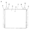
図1を参照して、この発明の一実施例である電気融着継手10は、ポリエチレンによって形成される継手本体12を備えており、被覆ポリエチレン管100どうしを接続するために用いられる。
Referring to FIG. 1, an electrofusion joint 10 according to an embodiment of the present invention includes a
ここで、電気融着継手10の具体的な説明に先立って、被覆ポリエチレン管100について説明しておく。
Here, prior to specific description of the electrofusion joint 10, the
被覆ポリエチレン管100は、図2(a)に示すように、内管(本体層)102、およびこの内管102の外周面を被覆する外層(被覆層)104を含む、ガスや水道のための導管である。
As shown in FIG. 2A, the
内管102は、所定長さ(たとえば5m等)の定尺管であり、ポリエチレンによって形成され、所定の口径および厚みに設定される。外層104は、たとえば軟質ポリエチレン等からなり、内管102の紫外線等による劣化を防止するために、耐候性が付与されている。
The
外層104は、内管102の外周面全体にわたって設けられてこれを被覆しており、その厚みは、たとえば1.5mmである。そして、図2(b)に示すように、電気融着継手10と融着接合するときに、接合に供する部分の外層104を除去することで、良好な接合のための融着面106を得ることができる。
The
このような被覆ポリエチレン管100は、従来公知の方法によって製造することができるので、その製造方法の詳細な説明は省略する。簡単に言えば、先に単独で押出された内管102に対して、さらに外層104を共押出して内管102の外周面を被覆することによって製造される。
Since such a
電気融着継手10の説明に戻って、電気融着継手10は、2つの被覆ポリエチレン管100を直線状に接続するためのものであり、継手本体12、および継手本体12の表面に被せられる熱収縮チューブ14を備えている。
Returning to the description of the electrical fusion joint 10, the electrical fusion joint 10 is for connecting two
図3および図4に示すように、継手本体12は、たとえば円筒状に形成される。継手本体12の両端開口部は、被覆ポリエチレン管100の管端を受容する受口16となり、その内面には、電熱線18が埋め込まれている。受口16の内径は、たとえば126mmである。そして、継手本体12の内面における電熱線18より奥側、すなわち継手本体12の中央部内面には、被覆ポリエチレン管100の管端を止めるストッパ20が形成されている。
As shown in FIGS. 3 and 4, the
継手本体12の外面に形成されている突起は、電熱線18と接続している端子部22であり、この端子部22よりも中央側には、受口16の内面と被覆ポリエチレン管100の融着面106とが融着したことを示すためのインジケータ24が形成されている。インジケータ24は、電熱線18によって溶融された樹脂の圧力が自身の根元に作用することによって上昇し、受口16の内面と被覆ポリエチレン管100の融着面106とを正しく融着できていることの目安にされる。
The protrusion formed on the outer surface of the
たとえば、受口16の内面と被覆ポリエチレン管100の融着面106とを融着させるときは、被覆ポリエチレン管100の管端を継手本体12の受口16にストッパ20に当接するまで挿入し、その後、コントローラから端子部22を介して電熱線18に通電する。
For example, when the inner surface of the receiving
また、上述したように、継手本体12の表面には、熱収縮チューブ(被覆層)14が被せられている。
Further, as described above, the surface of the
熱収縮チューブ14は、EPDM(エチレンプロピレンジエンモノマ)等からなる、加熱処理を施すことによって収縮するチューブである。後に詳細を説明するように、継手本体12の表面に被せられる前の熱収縮チューブ14の径は、継手本体12の外径より大きく設定されている。そして、ギヤーオーブン等の加熱炉内で加熱されることによって熱収縮チューブ14は縮径し、継手本体12の表面に密着して、継手本体12の表面に紫外線等による劣化を防止するための被覆層を形成する。
The heat-
熱収縮チューブ14は、継手本体12の表面を被覆する本体26を含み、その厚みは、たとえば1.5mmである。図5に示すように、本体26には、本体26を厚み方向に貫通する2つの挿通孔28,30が形成されている。一方の挿通孔28は、継手本体12の端子部22に対応する位置に形成され、継手本体12の外面から突き出している端子部22が挿通される。また、他方の挿通孔30は、継手本体12のインジケータ24に対応する位置に形成され、受口16の内面と被覆ポリエチレン管100の融着面106とが正しく融着されたときに上昇したインジケータ24が挿通されることとなる。
The heat-
図3および図4に戻って、本体26の両端部は、継手本体12の受口16の開口端よりも軸方向外側に突き出しており、そこに環状の鍔部32が形成されている。鍔部32は、継手本体12の受口16が被覆ポリエチレン管100の管端を受容したときに、受口16の開口端と被覆ポリエチレン管100の外層104との間にできる隙間(つまり、被覆ポリエチレン管100に残った外層104までの範囲)を上方から被覆することが可能な長さを有しており、この実施例では、たとえば12mmである。この鍔部32の軸方向の長さは、詳細は後に説明するように、リング体34の軸方向の長さに対応して設定されている。また、鍔部32の内径は、リング体34の外径に対応して、被覆ポリエチレン管100の外径(つまり、外層104の外径)より大きくなるように設定されており、この実施例では、たとえば140mmである。
Returning to FIG. 3 and FIG. 4, both end portions of the
図6−図10を参照して、継手本体12の表面に熱収縮チューブ14を被せる方法を以下に示す。
With reference to FIGS. 6 to 10, a method of covering the surface of the
先ず、収縮前の熱収縮チューブ14の内部に継手本体12を収容する。そして、図6に示すように、継手本体12の受口16に、リング体34および収縮防止コア40を取り付ける。
First, the
ここで、図7を参照して、リング体34の構成について詳細に説明する。図7に示すように、リング体34は、熱収縮チューブ14の鍔部32を形成するためのものであり、焼き入れ処理を施した鉄などの素材からなり、中空リング状に形成される本体36を含む。本体36の軸方向の長さは、たとえば12mmであり、その外径は、たとえば140mmである。本体36の内周面には、軸方向の一方端に、環状に突き出す凸部38が形成されている。凸部38は、径方向の内側に向けて突出し、その先端面の径(つまり、凸部38の内径)は、加熱冷却後の継手本体12の受口16の内径が規定値になるようにそれに応じた所定の値に設定されている。
Here, with reference to FIG. 7, the structure of the
さらに、図8を参照して、収縮防止コア40の構成について詳細に説明する。図8に示すように、収縮防止コア40は、ギヤーオーブン等の加熱炉内で加熱処理を施すときに継手本体12の受口16の形状を保持するためのものであり、たとえばアルミニウム等の金属からなり、一方端が開口した略中空円柱状に形成される本体42を有している。
Further, the configuration of the
本体42の外径は、加熱冷却後の継手本体12の受口16の内径が規定値になるようにそれに応じた所定の値に設定されており、たとえば126mmである。また、本体42の他方端は、段差状に拡径しており、そこに段差部44が形成されている。段差部44の外径は、リング体34の本体36の内径と略等しく設定され、たとえば130mmである。また、本体40の他方端には、継手本体12の受口16から収縮防止コア40をから取り外すときに、エアシリンダ等で収縮防止コア40を引っ張り出すための把持部46形成されている。把持部46の形状は特に問わないが、この実施例では、本体40の他方端面の中央部に、ねじ孔48が形成されており、そこにねじ棒50が取り付けられる。ねじ棒50には雄ねじが切られていて、この雄ねじが本体40のねじ孔48の雌ねじに螺合され、ナット52で固定されている。また、ねじ棒50の先端には、ナット54が螺合されている。
The outer diameter of the
図6に戻って、継手本体12の受口16にリング体34および収縮防止コア40を取り付けるときには、熱収縮チューブ14の鍔部32内にリング体34を挿入して、本体36の一方側(凸部38側)の軸方向端面を受口16の開口端に沿わせるとともに、凸部38の先端面が受口16の内面と面一になるように配置する。そして、収縮防止コア40を、その段差部44がリング体34の凸部38に係止されるまで、リング体34および継手本体12の受口16内に挿入する。
Returning to FIG. 6, when attaching the
継手本体12の受口16へのリング体34および収縮防止コア40の取り付けが終了すると、それらを熱収縮チューブ14が収縮する所定の温度に加熱しておいたギヤーオーブン等の加熱炉の中に入れて、所定の時間、たとえば10〜15分間加熱する。なお、熱収縮チューブ14の本体26には、予め挿通孔28を穿孔しておき、加熱前にその挿通孔28に端子部22を挿通させておく。
When the attachment of the
すると、熱収縮チューブ14が径方向に収縮して(つまり、縮径して)、継手本体12の外表面に密着する。このとき、継手本体12の受口16は、加熱炉の加熱によって収縮しようとするが、その内面側から収縮防止コア40に押さえられることにより、形状および寸法が保持される。また、熱収縮チューブ14の鍔部32は、加熱炉の加熱によって収縮するものの、その内面側からリング体34に押さえられることにより、リング体34の外形に沿う形状に保持される。
Then, the heat-
加熱処理が完了すると、冷却水槽等を通過させて、熱収縮チューブ14を適宜冷却固化させる。
When the heat treatment is completed, the
それから、図9に示すように、本体36の他方側の軸方向端面に沿って熱収縮チューブ14の鍔部32をカットし、続いて、リング体34を固定的に押さえつつ、エアシリンダ等で収縮防止コア40の把持部46を引っ張ることによって、図8に示すように、継手本体12の受口16から収縮防止コア40を取り外す。
Then, as shown in FIG. 9, the
最後に、鍔部32内に配置したリング体34を取り外し、熱収縮チューブ14の本体26に、インジケータ24を挿通させるための挿通孔30を形成して、作業を終了する。
Finally, the
さらに、図1を参照して、このような電気融着継手10を用いて被覆ポリエチレン管100どうしを接続した被覆ポリエチレン管路200を構成する方法を以下に示す。
Furthermore, with reference to FIG. 1, the method of comprising the coated
先ず、被覆ポリエチレン管100の具体的には、カッターナイフや被覆層除去用の専用工具(図示せず)等を用いて、被覆ポリエチレン管100の外層104の表面に切込みを入れ、その部分から外層104を引き裂いて剥ぎ取る。そして、被覆ポリエチレン管100の管端部に図2(b)に示すような融着面106を得る。そして、融着面106の清掃作業を行い、その管端部を電気融着継手10の一方の受口16に挿入する。
First, specifically, the
続いて、上述と別の被覆ポリエチレン管100の、接合に供する部分の外層104を除去して(つまり、融着面106を得て)、融着面106の清掃作業を行い、その管端部を電気融着継手10の他方の受口16に挿入する。
Subsequently, the
次に、図示しないコントローラの電源ケーブルを電源に接続し、電源のスイッチを入れて起動する。そして、コントローラから延びる出力ケーブルの接続端子を電気融着継手10の端子部22に接続する。そして、電熱線18に電流を流すと熱が発生し、この熱によって受口16の内面と被覆ポリエチレン管100の融着面106とを溶融して電気融着接合を行う。なお、受口16の内面と被覆ポリエチレン管100の融着面106とが正しく融着されたときに、継手本体12のインジケータ24が上昇するが、その上昇したインジケータ24は挿通孔30に挿通される。
Next, a controller power cable (not shown) is connected to the power source, and the power source is turned on to start up. Then, the connection terminal of the output cable extending from the controller is connected to the
通電後、融着面が冷却固化すると、熱収縮チューブ14の挿通孔28,30から外部に突き出している電気融着継手10の端子部22およびインジケータ24をカッターなどで除去する。そして、挿通孔28,30をブチルテープ等の防水テープ(図示せず)によって密封し、作業を終了する。ただし、インジケータ24の上昇度合いが小さい場合には、必ずしもインジケータ24を除去する必要はなく、そのまま上昇したインジケータ24ごと挿通孔30を防水テープによって密封するようにしてもよい。
After the energization, when the fusion surface is cooled and solidified, the
この実施例では、継手本体12の受口16の開口端と被覆ポリエチレン管100の外層104との間にできる隙間を熱収縮チューブ14の鍔部32によって覆うことができるので、被覆ポリエチレン管100どうしを電気融着継手10で接続した際に、被覆ポリエチレン管100の融着面106が外部に露出することがなく、この融着面106についても紫外線等による劣化を防止することが可能である。
In this embodiment, the gap formed between the open end of the receiving
つまり、電気融着継手10を用いて被覆ポリエチレン管100を接続して管路を構成する際に、継手本体12の受口16と被覆ポリエチレン管100の融着面106とを融着接合するだけで、管路全体に耐候性を付与することが可能である。したがって、特許文献1のように、施工現場での2度の通電(融着)作業をする必要がなく、その分だけ作業性が向上される。
That is, when the
しかも、熱収縮チューブ14を継手本体12の表面に密着させることによって、継手本体12の表面に被覆層を形成するようにしたため、被覆層が外部からの衝撃に対して強く、被覆層の脱落などが生じにくいので、それに起因する耐候性の劣化の可能性を抑制することができる。
Moreover, since the coating layer is formed on the surface of the
また、被覆層の脱落などが生じにくいことにより、たとえば管路が外部に露出するような環境であっても問題なく電気融着継手10を適用することができる。 Further, since the covering layer is less likely to drop off, for example, the electrofusion joint 10 can be applied without any problem even in an environment in which the pipe line is exposed to the outside.
さらに、この実施例では、継手本体12を熱収縮チューブ14に収容し、そして受口16に収縮防止コア40を挿入した状態で加熱炉内で加熱することによって、熱収縮チューブ14を継手本体12の表面に被せるようにした。したがって、加熱炉内での加熱中に、熱収縮しようとする継手本体12の受口16がその内面側から収縮防止コア40で押さえられるので、受口16の形状や寸法を保持することが可能である。
Further, in this embodiment, the joint
ここで、電気融着継手10の受口16の形状が少しでも変形してしまうと、受口16に被覆ポリエチレン管100を挿入できなくなる等の接合不良を生じる危険性がある。
Here, if the shape of the receiving
しかしながら、この実施例によれば、継手本体12をその受口16に収縮防止コア40を挿入した状態で加熱することにより、受口16の変形が収縮防止コア40によって抑制されるので、電気融着継手10と被覆ポリエチレン管100との間での接合不良の発生を防止することが可能である。
However, according to this embodiment, since the
さらにまた、この実施例では、鍔部32内にリング体34を挿入した状態で熱収縮チューブ14を加熱炉内で加熱することにより、鍔部32をリング体34の外形に沿った形状に形成するようにしたため、熱収縮チューブ14の鍔部32の内径を適切な寸法に設定することができる。
Furthermore, in this embodiment, the
なお、上述の実施例では、ソケット型の継手本体12の表面に熱収縮チューブ14を被せた場合を示したが、これに限定される必要はなく、ベンド型、フランジ型またはエルボ型等のような他のタイプの継手本体12の表面に熱収縮チューブ14を被せるようにしてもよい。ただし、そのような他のタイプの継手本体12の表面の全体を1つの熱収縮チューブ14によって被覆することが困難である場合には、複数の熱収縮チューブ14を用意し、それらを隣接する熱収縮チューブ14の端部どうしが重なるように継手本体12の表面に被せると、継手本体12の表面の全体を確実に被覆することができるので好適である。
In the above-mentioned embodiment, the case where the surface of the socket-type
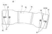
一例を挙げると、この発明の他の一実施例である電気融着継手10では、継手本体12は曲管部56を含んでおり、2つの被覆ポリエチレン管100を曲線状に接続する。以下、図1に示す電気融着継手10と共通する部分については同じ番号を付して、重複する説明は省略する。
For example, in an electrofusion joint 10 according to another embodiment of the present invention, the
図12および図13に示すように、曲管部56は、所定の曲げ角度(この実施例では、11.25度)を有する曲管状に形成され、その両端開口部が、被覆ポリエチレン管100の管端を受容する受口16となる。そして、受口16のそれぞれが、電気融着継手部58として形成されている。各受口16の内面には、電熱線18が埋め込まれる。また、各受口18の外面には、電熱線18と接続している2つの端子部22と1つのインジケータ24が突出して形成される。
As shown in FIGS. 12 and 13, the
継手本体12の表面には、熱収縮チューブ14が被せられており、熱収縮チューブ14の本体26には、各受口16の端子部22およびインジケータ24に対応する位置に挿通孔28,30が形成されている。また、本体26の両端部は、各受口16の開口端よりも軸方向外側に突き出しており、そこに環状の鍔部32が形成されている。鍔部32は、図14に示すように、継手本体12の受口16が被覆ポリエチレン管100の管端を受容したときに、受口16の開口端と被覆ポリエチレン管100の外層104との間にできる隙間を上方から覆う。
The surface of the
このような継手本体12の表面に被覆層を形成する場合には、図示は省略するが、収縮前の熱収縮チューブ14の内部に継手本体12を収容する。そして、継手本体12の各受口16に、リング体34および収縮防止コア40をそれぞれ取り付ける。
In the case where a coating layer is formed on the surface of the
続いて、それらをギヤーオーブン等の加熱炉の中に入れて、所定温度で所定時間加熱することにより、熱収縮チューブ14を縮径させて、継手本体12の表面に密着させる。加熱処理が完了すると、冷却水槽等を通過させて、熱収縮チューブ14を適宜冷却固化させる。
Subsequently, they are put in a heating furnace such as a gear oven and heated at a predetermined temperature for a predetermined time, whereby the
それから、リング体34の軸方向端面に沿って熱収縮チューブ14の鍔部32をカットして、その後、収縮防止コア40を取り外し、さらに鍔部32内に配置したリング体34を取り外して、作業を終了する。
Then, the
この実施例においても、図1の実施例と同様に、簡単な作業で管路全体に耐候性を付与することができるので、作業性に優れる。また、継手本体12を外面被覆する被覆層が外部からの衝撃に対して強く、被覆層の脱落などが生じにくいので、それに起因する耐候性の劣化の可能性を抑制することができる。
Also in this embodiment, as in the embodiment of FIG. 1, weather resistance can be imparted to the entire pipe line with a simple operation, and therefore, workability is excellent. Moreover, since the coating layer which coat | covers the outer surface of the joint
なお、この実施例では、継手本体12は曲げ角度が11.25度の曲管部56を含んでいたが、これに限定される必要はなく、曲げ角度が90度、45度、22.5度の曲管部を含む継手本体12を用いても同様である。
In this embodiment, the
さらに、上述の実施例では、継手本体12の受口16にリング体34および収縮防止コア40を取り付けるときに、熱収縮チューブ14の鍔部32内にリング体34を挿入して、本体36の軸方向端面を受口16の開口端に沿わせて、凸部38の先端面が受口16の内面と面一になるように配置したが、これに限定される必要はない。
Furthermore, in the above-described embodiment, when the
たとえば、加熱炉内での加熱中に、熱収縮する鍔部32を内面側から押さえることによって、鍔部32をその内径が被覆ポリエチレン管100の外径よりも大きくなる形状に保持することができるのであれば、リング体34の形状は特に問わない。
For example, during heating in the heating furnace, the
また、収縮防止コア40を、その段差部44がリング体34の凸部38に係止されるまで、リング体34および継手本体12の受口16内に挿入したが、これに限定される必要もない。
Further, the
たとえば、加熱炉内での加熱中に、熱収縮しようとする継手本体12の受口16をその内面側から押さえることによって、継手本体12の受口16の形状および寸法を保持することができるのであれば、収縮防止コア40の形状も特に問わない。
For example, the shape and dimensions of the receiving
一例を挙げると、収縮防止コア40の本体42の外周面に、塗料により記載する、または紙等に記載したものを張り付けることによって、収縮防止コア40を挿入する際の位置決めの目安を表示するようにすれば、収縮防止コア40の段差部44をリング体34の凸部38に係止させる必要はない。つまり、収縮防止コア40に段差部44を形成する必要はなく、リング体34の内周面に凸部38を形成する必要もない。
As an example, an indication of positioning when inserting the
さらに、加熱炉内での加熱処理の後で、継手本体12の受口16から収縮防止コア40を取り外すことができるのであれば、収縮防止コア40の本体42の他方端に、必ずしも把持部46を形成する必要はない。
Further, if the
さらにまた、リング体34を収縮防止コア40と一体的に形成するようにしてもよい。たとえば、上述の実施例では、継手本体12の受口16から収縮防止コア40を取り外すときに、リング体34を固定的に押さえつつ、エアシリンダ等で収縮防止コア40の把持部46を引っ張るようにしたが、リング体34を収縮防止コア40と一体的に形成した場合には、継手本体12の受口16から収縮防止コア40を取り外す際に、継手本体12をバイス(万力)等で固定した状態で、エアシリンダ等で収縮防止コア40の把持部46を引っ張るようにすると好適である。
Furthermore, the
なお、上述した径や高さ等の具体的数値は、いずれも単なる一例であり、必要に応じて適宜変更可能である。 It should be noted that the specific numerical values such as the diameter and height described above are merely examples, and can be appropriately changed as necessary.
10 …電気融着継手
12 …継手本体
14 …熱収縮チューブ
16 …受口
18 …電熱線
22 …端子部
24 …インジケータ
28,30 …挿通孔
32 …鍔部
34 …リング体
40 …収縮防止コア
100 …被覆ポリエチレン管
102 …内管
104 …外層
200 …被覆ポリエチレン管路
DESCRIPTION OF
Claims (5)
ポリエチレンからなり、前記被覆ポリエチレン管の管端を受容する受口を有する継手本体、および
前記継手本体の表面に被せられ、前記受口の開口端から軸方向に突出するかつ内径が前記被覆ポリエチレン管の外径より大きい鍔部を有する熱収縮チューブを備える、被覆ポリエチレン管用電気融着継手。 An electric fusion joint for coated polyethylene pipes used to connect the coated polyethylene pipes,
A joint body made of polyethylene and having a receiving port for receiving the pipe end of the coated polyethylene pipe, and is covered with the surface of the fitting main body and protrudes axially from the opening end of the receiving port, and has an inner diameter that is the coated polyethylene pipe An electrofusion joint for a coated polyethylene pipe, comprising a heat-shrinkable tube having a flange portion that is larger than the outer diameter.
前記熱収縮チューブには、前記端子部および前記インジケータを挿通させるための挿通孔が形成される、請求項1記載の被覆ポリエチレン管用電気融着継手。 The joint body is provided with a heating wire embedded in an inner surface of the receiving port, a terminal portion provided to project from the outer surface of the receiving port and energizing the heating wire, and a projecting surface from the outer surface of the receiving port. And an indicator for indicating that the inner surface of the receiving port and the pipe end of the coated polyethylene pipe are fused,
The electrofusion joint for coated polyethylene pipes according to claim 1, wherein an insertion hole for inserting the terminal portion and the indicator is formed in the heat shrinkable tube.
前記被覆ポリエチレン管の接合に供する部分の前記外層を除去する長さを、前記継手本体の受口が前記被覆ポリエチレン管の管端部を受容したときに前記熱収縮チューブの鍔部によって前記被覆ポリエチレン管の残りの外層までの範囲を被覆可能な所定の長さに設定し、
さらに前記被覆ポリエチレン管と前記被覆ポリエチレン管用電気融着継手とを融着接合した後で、前記継手本体の端子部を除去して、前記熱収縮チューブの挿通孔を密封するようにした、被覆ポリエチレン管路。 5. A coated polyethylene pipe in which coated polyethylene pipes, in which the outer peripheral surface of an inner pipe formed of polyethylene is coated with an outer layer, are joined using the electric fusion joint for coated polyethylene pipes according to any one of claims 1 to 4. ,
The length of the outer layer to be removed from the portion to be joined to the coated polyethylene pipe is set to a length that allows the joint body to receive the pipe end portion of the coated polyethylene pipe by the flange of the heat-shrinkable tube. Set the range to the remaining outer layer of the tube to a predetermined length that can be covered,
Furthermore, after the fusion-bonded polyethylene pipe and the electro-welded joint for the coated polyethylene pipe are fusion-bonded, the terminal portion of the joint body is removed to seal the insertion hole of the heat-shrinkable tube. Pipeline.
Priority Applications (1)
| Application Number | Priority Date | Filing Date | Title |
|---|---|---|---|
| JP2011030406A JP5706181B2 (en) | 2011-02-16 | 2011-02-16 | Electrofused joint for coated polyethylene pipe and coated polyethylene pipe using the same |
Applications Claiming Priority (1)
| Application Number | Priority Date | Filing Date | Title |
|---|---|---|---|
| JP2011030406A JP5706181B2 (en) | 2011-02-16 | 2011-02-16 | Electrofused joint for coated polyethylene pipe and coated polyethylene pipe using the same |
Publications (2)
| Publication Number | Publication Date |
|---|---|
| JP2012167768A true JP2012167768A (en) | 2012-09-06 |
| JP5706181B2 JP5706181B2 (en) | 2015-04-22 |
Family
ID=46972112
Family Applications (1)
| Application Number | Title | Priority Date | Filing Date |
|---|---|---|---|
| JP2011030406A Active JP5706181B2 (en) | 2011-02-16 | 2011-02-16 | Electrofused joint for coated polyethylene pipe and coated polyethylene pipe using the same |
Country Status (1)
| Country | Link |
|---|---|
| JP (1) | JP5706181B2 (en) |
Cited By (2)
| Publication number | Priority date | Publication date | Assignee | Title |
|---|---|---|---|---|
| JP2016188696A (en) * | 2015-03-30 | 2016-11-04 | 積水化学工業株式会社 | Connection structure and connection method for piping |
| CN112178337A (en) * | 2020-08-25 | 2021-01-05 | 临海伟星新型建材有限公司 | Connecting structure and connecting method of fiber reinforced composite pipe |
Citations (7)
| Publication number | Priority date | Publication date | Assignee | Title |
|---|---|---|---|---|
| JP2002039488A (en) * | 2000-07-18 | 2002-02-06 | Osaka Gas Co Ltd | Pipe connecting structure and pipe fitting |
| JP2002181275A (en) * | 2000-12-15 | 2002-06-26 | Erc:Kk | Connecting structure of plastic tube |
| JP2003130275A (en) * | 2001-10-26 | 2003-05-08 | Sekisui Chem Co Ltd | Pipe connection method |
| US20060027536A1 (en) * | 2004-08-09 | 2006-02-09 | Airbus Deutschland Gmbh | Heating sleeve for shrinking on of shrink tube connections |
| JP2007040443A (en) * | 2005-08-04 | 2007-02-15 | Mesco Inc | Joint construction of plastic pipe |
| JP2007051733A (en) * | 2005-08-19 | 2007-03-01 | Sekisui Chem Co Ltd | Pipe joint, its forming method, and piping connection method using the same |
| JP2007225001A (en) * | 2006-02-23 | 2007-09-06 | Sekisui Chem Co Ltd | Electrofusion joint |
-
2011
- 2011-02-16 JP JP2011030406A patent/JP5706181B2/en active Active
Patent Citations (7)
| Publication number | Priority date | Publication date | Assignee | Title |
|---|---|---|---|---|
| JP2002039488A (en) * | 2000-07-18 | 2002-02-06 | Osaka Gas Co Ltd | Pipe connecting structure and pipe fitting |
| JP2002181275A (en) * | 2000-12-15 | 2002-06-26 | Erc:Kk | Connecting structure of plastic tube |
| JP2003130275A (en) * | 2001-10-26 | 2003-05-08 | Sekisui Chem Co Ltd | Pipe connection method |
| US20060027536A1 (en) * | 2004-08-09 | 2006-02-09 | Airbus Deutschland Gmbh | Heating sleeve for shrinking on of shrink tube connections |
| JP2007040443A (en) * | 2005-08-04 | 2007-02-15 | Mesco Inc | Joint construction of plastic pipe |
| JP2007051733A (en) * | 2005-08-19 | 2007-03-01 | Sekisui Chem Co Ltd | Pipe joint, its forming method, and piping connection method using the same |
| JP2007225001A (en) * | 2006-02-23 | 2007-09-06 | Sekisui Chem Co Ltd | Electrofusion joint |
Cited By (2)
| Publication number | Priority date | Publication date | Assignee | Title |
|---|---|---|---|---|
| JP2016188696A (en) * | 2015-03-30 | 2016-11-04 | 積水化学工業株式会社 | Connection structure and connection method for piping |
| CN112178337A (en) * | 2020-08-25 | 2021-01-05 | 临海伟星新型建材有限公司 | Connecting structure and connecting method of fiber reinforced composite pipe |
Also Published As
| Publication number | Publication date |
|---|---|
| JP5706181B2 (en) | 2015-04-22 |
Similar Documents
| Publication | Publication Date | Title |
|---|---|---|
| US5398974A (en) | Pipe connecting member | |
| EP0585974B1 (en) | Electrofusion joint and hot water supply header using the same | |
| EP2800921B1 (en) | Heat-shrinkable tube covering | |
| US5925427A (en) | Support core ribbon for cold-shrink tube | |
| EP2612063B1 (en) | Coupling piece for multilayered conduits, method for coupling and assembly obtained by the method. | |
| JP5706181B2 (en) | Electrofused joint for coated polyethylene pipe and coated polyethylene pipe using the same | |
| JP5688282B2 (en) | Manufacturing method of piping materials | |
| JP2007040329A (en) | Pipe connector | |
| JPH02309090A (en) | Synthetic resin pipe joint and manufacture thereof | |
| JPH0736233Y2 (en) | Union socket for plastic pipes | |
| JP2012172688A (en) | Structure and method for connecting composite pipe | |
| JPH06265082A (en) | Electric fusion coupling | |
| JP5976457B2 (en) | Clad pipeline, its construction method, and cover | |
| JP2006077913A (en) | Branch connection for insertion and replacing or remaking method using the same | |
| KR20150005067A (en) | Structure for connecting spiral-wave formed pipes | |
| WO2023054699A1 (en) | Piping member and method for manufacturing piping member | |
| JP2018162858A (en) | Electric fusion joint | |
| JPH06147386A (en) | Connecting structure for two-layer pipe | |
| JP2008019971A (en) | Pipe connection structure and cover member | |
| JP6666775B2 (en) | Electrofusion joint and method of manufacturing electrofusion joint | |
| JP2864507B2 (en) | Plastic pipe fusion joints | |
| JP2009228835A (en) | Insulating pipe | |
| JP2023148546A (en) | Piping member, piping structure, and method of manufacturing piping member | |
| KR200214753Y1 (en) | electronic socket for spiral hollow pipe | |
| JP2002323171A (en) | Cutting method, jointing method, and jointing structure of flexible tube |
Legal Events
| Date | Code | Title | Description |
|---|---|---|---|
| A625 | Written request for application examination (by other person) |
Free format text: JAPANESE INTERMEDIATE CODE: A625 Effective date: 20130924 |
|
| A977 | Report on retrieval |
Free format text: JAPANESE INTERMEDIATE CODE: A971007 Effective date: 20140618 |
|
| A131 | Notification of reasons for refusal |
Free format text: JAPANESE INTERMEDIATE CODE: A131 Effective date: 20140722 |
|
| A521 | Written amendment |
Free format text: JAPANESE INTERMEDIATE CODE: A523 Effective date: 20140917 |
|
| TRDD | Decision of grant or rejection written | ||
| A01 | Written decision to grant a patent or to grant a registration (utility model) |
Free format text: JAPANESE INTERMEDIATE CODE: A01 Effective date: 20150217 |
|
| A61 | First payment of annual fees (during grant procedure) |
Free format text: JAPANESE INTERMEDIATE CODE: A61 Effective date: 20150226 |
|
| R150 | Certificate of patent or registration of utility model |
Ref document number: 5706181 Country of ref document: JP Free format text: JAPANESE INTERMEDIATE CODE: R150 |
|
| S533 | Written request for registration of change of name |
Free format text: JAPANESE INTERMEDIATE CODE: R313533 |
|
| R350 | Written notification of registration of transfer |
Free format text: JAPANESE INTERMEDIATE CODE: R350 |