JP2012167607A - Control apparatus for internal combustion engine with supercharger - Google Patents
Control apparatus for internal combustion engine with supercharger Download PDFInfo
- Publication number
- JP2012167607A JP2012167607A JP2011029542A JP2011029542A JP2012167607A JP 2012167607 A JP2012167607 A JP 2012167607A JP 2011029542 A JP2011029542 A JP 2011029542A JP 2011029542 A JP2011029542 A JP 2011029542A JP 2012167607 A JP2012167607 A JP 2012167607A
- Authority
- JP
- Japan
- Prior art keywords
- fuel
- supercharger
- fuel injection
- engine
- injection
- Prior art date
- Legal status (The legal status is an assumption and is not a legal conclusion. Google has not performed a legal analysis and makes no representation as to the accuracy of the status listed.)
- Withdrawn
Links
Images

Classifications
-
- F—MECHANICAL ENGINEERING; LIGHTING; HEATING; WEAPONS; BLASTING
- F02—COMBUSTION ENGINES; HOT-GAS OR COMBUSTION-PRODUCT ENGINE PLANTS
- F02D—CONTROLLING COMBUSTION ENGINES
- F02D41/00—Electrical control of supply of combustible mixture or its constituents
- F02D41/30—Controlling fuel injection
- F02D41/3094—Controlling fuel injection the fuel injection being effected by at least two different injectors, e.g. one in the intake manifold and one in the cylinder
-
- F—MECHANICAL ENGINEERING; LIGHTING; HEATING; WEAPONS; BLASTING
- F02—COMBUSTION ENGINES; HOT-GAS OR COMBUSTION-PRODUCT ENGINE PLANTS
- F02D—CONTROLLING COMBUSTION ENGINES
- F02D41/00—Electrical control of supply of combustible mixture or its constituents
- F02D41/0002—Controlling intake air
- F02D41/0007—Controlling intake air for control of turbo-charged or super-charged engines
-
- F—MECHANICAL ENGINEERING; LIGHTING; HEATING; WEAPONS; BLASTING
- F02—COMBUSTION ENGINES; HOT-GAS OR COMBUSTION-PRODUCT ENGINE PLANTS
- F02D—CONTROLLING COMBUSTION ENGINES
- F02D41/00—Electrical control of supply of combustible mixture or its constituents
- F02D41/02—Circuit arrangements for generating control signals
- F02D41/04—Introducing corrections for particular operating conditions
- F02D41/10—Introducing corrections for particular operating conditions for acceleration
-
- F—MECHANICAL ENGINEERING; LIGHTING; HEATING; WEAPONS; BLASTING
- F02—COMBUSTION ENGINES; HOT-GAS OR COMBUSTION-PRODUCT ENGINE PLANTS
- F02D—CONTROLLING COMBUSTION ENGINES
- F02D2200/00—Input parameters for engine control
- F02D2200/02—Input parameters for engine control the parameters being related to the engine
- F02D2200/04—Engine intake system parameters
- F02D2200/0406—Intake manifold pressure
-
- F—MECHANICAL ENGINEERING; LIGHTING; HEATING; WEAPONS; BLASTING
- F02—COMBUSTION ENGINES; HOT-GAS OR COMBUSTION-PRODUCT ENGINE PLANTS
- F02D—CONTROLLING COMBUSTION ENGINES
- F02D2250/00—Engine control related to specific problems or objectives
- F02D2250/38—Control for minimising smoke emissions, e.g. by applying smoke limitations on the fuel injection amount
-
- Y—GENERAL TAGGING OF NEW TECHNOLOGICAL DEVELOPMENTS; GENERAL TAGGING OF CROSS-SECTIONAL TECHNOLOGIES SPANNING OVER SEVERAL SECTIONS OF THE IPC; TECHNICAL SUBJECTS COVERED BY FORMER USPC CROSS-REFERENCE ART COLLECTIONS [XRACs] AND DIGESTS
- Y02—TECHNOLOGIES OR APPLICATIONS FOR MITIGATION OR ADAPTATION AGAINST CLIMATE CHANGE
- Y02T—CLIMATE CHANGE MITIGATION TECHNOLOGIES RELATED TO TRANSPORTATION
- Y02T10/00—Road transport of goods or passengers
- Y02T10/10—Internal combustion engine [ICE] based vehicles
- Y02T10/12—Improving ICE efficiencies
Landscapes
- Engineering & Computer Science (AREA)
- Chemical & Material Sciences (AREA)
- Combustion & Propulsion (AREA)
- Mechanical Engineering (AREA)
- General Engineering & Computer Science (AREA)
- Output Control And Ontrol Of Special Type Engine (AREA)
- Electrical Control Of Air Or Fuel Supplied To Internal-Combustion Engine (AREA)
- Combined Controls Of Internal Combustion Engines (AREA)
Abstract
Description
本発明は、燃焼室に吸入される空気を過給する過給機を備えた過給機付き内燃機関の制御装置に関する。 The present invention relates to a control device for a supercharged internal combustion engine that includes a supercharger that supercharges air sucked into a combustion chamber.
車両などに搭載される内燃機関(以下、エンジンともいう)には、ポート噴射型エンジンや筒内直噴型エンジンが知られている。 As an internal combustion engine (hereinafter also referred to as an engine) mounted on a vehicle or the like, a port injection type engine or an in-cylinder direct injection type engine is known.
ポート噴射型エンジンは、吸気ポートに配置した燃料噴射弁(吸気通路用燃料噴射弁)から吸気通路内にガソリン等の燃料を噴射して均質な混合気を形成し、その混合気を燃焼室内に導入し、点火プラグにて点火する方式のエンジンである。 A port injection type engine injects fuel such as gasoline into an intake passage from a fuel injection valve (intake passage fuel injection valve) disposed in an intake port to form a homogeneous mixture, and the mixture is injected into a combustion chamber. This is an engine that is introduced and ignited by a spark plug.
筒内直噴型エンジンは、各気筒に燃料噴射弁(筒内用燃料噴射弁)を配置し、その燃料噴射弁からガソリン等の燃料を燃焼室内に直接噴射して、吸気ポートから燃焼室内に導入される吸入空気と混合して混合気を形成し、この混合気を点火プラグにより点火する方式のエンジンである。このような筒内用燃料噴射弁を備えたエンジンでは、内燃機関の圧縮行程に燃料を燃焼室内へ噴射し、点火時期において点火プラグ近傍だけに着火性の良好な混合気を形成させることで、燃焼室全体としては希薄な混合気の燃焼、いわゆる成層燃焼を実現することができる。 In-cylinder direct-injection engines have a fuel injection valve (in-cylinder fuel injection valve) in each cylinder, and fuel such as gasoline is directly injected into the combustion chamber from the fuel injection valve. This is an engine that mixes with introduced intake air to form an air-fuel mixture and ignites the air-fuel mixture with a spark plug. In an engine equipped with such an in-cylinder fuel injection valve, fuel is injected into the combustion chamber during the compression stroke of the internal combustion engine, and an air-fuel mixture having good ignitability is formed only in the vicinity of the spark plug at the ignition timing. The combustion chamber as a whole can realize the combustion of a lean air-fuel mixture, so-called stratified combustion.
また、筒内直噴型エンジンには、排気エネルギを利用した過給機(以下、ターボチャージャともいう)を備えたものがある(例えば、特許文献1参照)。ターボチャージャは、一般に、エンジンの排気通路を流れる排気ガスによって回転するタービンホイールと、吸気通路内の空気を強制的にエンジンの燃焼室へと送り込むコンプレッサインペラと、これらタービンホイールとコンプレッサインペラとを連結する連結シャフトとを備えている。このような構造のターボチャージャにおいては、排気通路に配置のタービンホイールが排気のエネルギによって回転し、これに伴って吸気通路に配置のコンプレッサインペラが回転することによって吸入空気が過給され、エンジンの各気筒の燃焼室に過給空気が強制的に送り込まれる。 Some in-cylinder direct injection engines include a supercharger (hereinafter also referred to as a turbocharger) that uses exhaust energy (see, for example, Patent Document 1). In general, a turbocharger connects a turbine wheel that is rotated by exhaust gas flowing through an engine exhaust passage, a compressor impeller that forcibly feeds air in the intake passage to a combustion chamber of the engine, and the turbine wheel and the compressor impeller. Connecting shaft. In the turbocharger having such a structure, the turbine wheel disposed in the exhaust passage is rotated by the energy of the exhaust gas, and the compressor impeller disposed in the intake passage is rotated accordingly, whereby the intake air is supercharged, and the engine Supercharged air is forced into the combustion chamber of each cylinder.
なお、筒内燃料噴射弁と過給機とを備えた内燃機関(エンジン)において、過給圧に応じて燃料噴射制御を行う技術に関するものとして、下記の特許文献2及び3に記載の技術がある。
In addition, in an internal combustion engine (engine) provided with a cylinder fuel injection valve and a supercharger, the techniques described in
ところで、過給機付き筒内直噴型エンジン(筒内用燃料噴射弁のみを備えたエンジン)においては、加速時にスモークが発生して排気エミッションが悪化する場合がある。すなわち、筒内用燃料噴射弁のみを備えたエンジンは、もともと混合気の均質度が低いエンジンであるため、加速時(機関加速時)にはスモーク、PN(Particle Number)、PM(Particle Matter)(以下、スモークと表記する)が発生する場合がある。 By the way, in a cylinder direct injection type engine with a supercharger (an engine having only a cylinder fuel injection valve), smoke may be generated during acceleration and exhaust emission may deteriorate. That is, an engine having only an in-cylinder fuel injection valve is originally an engine having a low homogeneity of the air-fuel mixture. (Hereinafter referred to as smoke) may occur.
本発明はそのような実情を考慮してなされたもので、筒内燃料噴射弁と過給機とを備えた内燃機関において、加速時の排気エミッションを改善することが可能な制御の実現を目的とする。 The present invention has been made in view of such a situation, and an object of the present invention is to realize control capable of improving exhaust emission during acceleration in an internal combustion engine having an in-cylinder fuel injection valve and a supercharger. And
本発明は、燃焼室内に燃料を直接噴射する筒内用燃料噴射弁と、吸気通路(吸気ポート等)に燃料を噴射する吸気通路用燃料噴射弁と、前記燃焼室に吸入される空気を過給する過給機とを備えた過給機付き内燃機関の制御装置を前提としており、このような過給付き内燃機関の制御装置において、加速時(内燃機関が加速される過渡時)に、前記過給機による過給圧が目標過給圧に上昇するまでの間、前記吸気通路用燃料噴射弁(ポート噴射用インジェクタ)からの燃料噴射のみを実行する燃料噴射制御手段を備えていることを技術的特徴としている。 The present invention includes an in-cylinder fuel injection valve that directly injects fuel into a combustion chamber, an intake passage fuel injection valve that injects fuel into an intake passage (such as an intake port), and air that is sucked into the combustion chamber. It is premised on a control device for an internal combustion engine with a supercharger provided with a supercharger for supplying, and in such a control device for an internal combustion engine with a supercharge, at the time of acceleration (when the internal combustion engine is accelerated), Fuel injection control means for performing only fuel injection from the intake passage fuel injection valve (port injection injector) until the supercharging pressure by the supercharger rises to the target supercharging pressure is provided. Is a technical feature.
本発明の具体的な構成として、過給機にて過給された吸気の実過給圧を認識する実過給圧認識手段と、内燃機関の運転状態(例えば、機関負荷など)に基づいて目標過給圧を設定する目標過給圧設定手段とを備え、加速時において上記実過給圧認識手段で認識される実過給圧が、上記目標過給圧設定手段にて設定される目標過給圧(加速時における目標過給圧)に上昇するまでの間、吸気通路用燃料噴射弁からの燃料噴射のみを実行する、という構成を挙げることができる。 As a specific configuration of the present invention, based on the actual supercharging pressure recognition means for recognizing the actual supercharging pressure of the intake air supercharged by the supercharger and the operating state (for example, engine load) of the internal combustion engine. A target boost pressure setting means for setting a target boost pressure, and a target boost pressure recognized by the actual boost pressure recognition means during acceleration is set by the target boost pressure setting means. A configuration in which only fuel injection from the fuel injection valve for intake passage is executed until the boost pressure (target boost pressure during acceleration) is increased can be given.
この場合、上記実過給圧認識手段の具体的な例として、過給機(コンプレッサインペラ)の下流側の吸気通路に配置される過給圧センサ(インマニ圧センサ)を挙げることができる。そして、その過給圧センサの出力から得られる実過給圧(機関加速時の実過給圧)が上記目標過給圧に上昇するまでの間、吸気通路用燃料噴射弁からの燃料噴射のみを行うようにすればよい。 In this case, as a specific example of the actual supercharging pressure recognition means, a supercharging pressure sensor (intake manifold pressure sensor) disposed in the intake passage on the downstream side of the supercharger (compressor impeller) can be cited. Until the actual boost pressure obtained from the output of the boost pressure sensor (actual boost pressure during engine acceleration) rises to the target boost pressure, only fuel injection from the fuel injection valve for the intake passage is performed. Should be done.
また、本発明において、加速時を判定する方法としては、例えば、アクセル開度(またはスロットル開度)の単位時間当たりの変化量が所定の判定閾値以上である場合に「加速時」であると判定する、という方法を挙げることができる。なお、加速判定閾値については、対象とするエンジン機種などを考慮して、実験・計算等によって適合した値を設定するようにすればよい。 Further, in the present invention, as a method for determining the acceleration time, for example, when the amount of change per unit time of the accelerator opening (or throttle opening) is equal to or greater than a predetermined determination threshold, “acceleration time” The method of judging can be mentioned. Note that the acceleration determination threshold value may be set to an appropriate value by experiment / calculation in consideration of the target engine model.
本発明によれば、加速時において実過給圧が目標過給圧に上昇するまでの間、つまり、ターボラグによる過給遅れが生じている間は、吸気通路用燃料噴射弁(ポート噴射用インジェクタ)からの燃料噴射のみを行うので、混合気の均質度を高くすることが可能となって空気の利用効率が高くなる。これによって、加速時におけるスモークの発生を抑制することができ、排気エミッションの改善を図ることができる。また、過給遅れ中の機関出力トルクの増大を図ることも可能で、ドライバビリティを改善することができる。 According to the present invention, the fuel injection valve for the intake passage (port injector) is used until the actual supercharging pressure rises to the target supercharging pressure during acceleration, that is, while the supercharging delay due to the turbo lag occurs. ), Only the fuel injection is performed, so that the homogeneity of the air-fuel mixture can be increased and the air utilization efficiency is increased. As a result, the generation of smoke during acceleration can be suppressed, and exhaust emission can be improved. Further, it is possible to increase the engine output torque during the delay in supercharging, and drivability can be improved.
本発明によれば、筒内燃料噴射弁と過給機とを備えた内燃機関において、加速時におけるスモークの発生を抑制することが可能になるので、排気エミッションを改善することができる。 According to the present invention, in an internal combustion engine provided with an in-cylinder fuel injection valve and a supercharger, it is possible to suppress the generation of smoke during acceleration, so that exhaust emission can be improved.
以下、本発明の実施形態を図面に基づいて説明する。 Hereinafter, embodiments of the present invention will be described with reference to the drawings.
まず、本発明を適用する内燃機関(以下、エンジンともいう)について説明する。 First, an internal combustion engine (hereinafter also referred to as an engine) to which the present invention is applied will be described.
−エンジン−
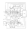
図1及び図2は本発明を適用するエンジンの概略構成を示す図である。なお、図2にはエンジンの1気筒の構成のみを示している。また、図2においてターボチャージャ及びEGR装置の図示は省略している。
-Engine-
1 and 2 are diagrams showing a schematic configuration of an engine to which the present invention is applied. FIG. 2 shows only the configuration of one cylinder of the engine. In FIG. 2, illustration of the turbocharger and the EGR device is omitted.
この例のエンジン1は、車両に搭載される4気筒ガソリンエンジンであって、その各気筒を構成するシリンダブロック1a内には上下方向に往復動するピストン1cが設けられている。ピストン1cはコネクティングロッド16を介してクランクシャフト15に連結されており、ピストン1cの往復運動がコネクティングロッド16によってクランクシャフト15の回転へと変換される。
The engine 1 of this example is a four-cylinder gasoline engine mounted on a vehicle, and a piston 1c that reciprocates in the vertical direction is provided in a cylinder block 1a constituting each cylinder. The piston 1c is connected to the
クランクシャフト15にはシグナルロータ17が取り付けられている。シグナルロータ17の外周面には複数の歯(突起)17aが等角度(この例では、例えば10°CA(クランク過度))ごとに設けられている。また、シグナルロータ17は、歯17aの2枚分が欠落した欠歯部17bを有している。
A
シグナルロータ17の側方近傍には、クランク角を検出するクランクポジションセンサ(エンジン回転数センサ)301が配置されている。クランクポジションセンサ301は、例えば電磁ピックアップであって、クランクシャフト15が回転する際にシグナルロータ17の歯17aに対応するパルス状の信号(電圧パルス)を発生する。このクランクポジションセンサ301の出力信号からエンジン回転数NEを算出することができる。
A crank position sensor (engine speed sensor) 301 for detecting a crank angle is disposed near the side of the
エンジン1のシリンダブロック1aにはエンジン冷却水の水温を検出する水温センサ303が配置されている。また、シリンダブロック1aの上端にはシリンダヘッド1bが設けられており、このシリンダヘッド1bとピストン1cとの間に燃焼室1dが形成されている。エンジン1の燃焼室1dには点火プラグ3が配置されている。点火プラグ3の点火タイミングはイグナイタ4によって調整される。イグナイタ4はECU(Electronic Control Unit)500によって制御される。
A
エンジン1のシリンダブロック1aの下部には、潤滑油(エンジンオイル)を貯留するオイルパン18が設けられている。オイルパン18に貯留された潤滑油は、エンジン1の運転時に、異物を除去するオイルストレーナを介してオイルポンプ(図示せず)によって汲み上げられて、ピストン1c、クランクシャフト15、コネクティングロッド16などエンジン各部に供給され、その各部の潤滑・冷却等に使用される。そして、このようにして供給された潤滑油は、エンジン各部の潤滑・冷却等のために使用された後、オイルパン18に戻され、再びオイルポンプによって汲み上げられるまでオイルパン18内に貯留される。
An
エンジン1の燃焼室1dには吸気通路11と排気通路12とが接続されている。吸気通路11の一部は吸気ポート11a及び吸気マニホールド11bによって形成されている。また、排気通路12の一部は排気ポート12a及び排気マニホールド12bによって形成されている。
An
吸気通路11には、吸入空気(新気)を濾過するエアクリーナ7、エアフロメータ304、後述するターボチャージャ100のコンプレッサインペラ102、ターボチャージャ100での過給によって昇温した吸入空気を強制冷却するためのインタークーラ8、エンジン1の吸入空気量を調整するためのスロットルバルブ5などが配置されている。また、吸気通路11(吸気マニホールド11b)には、吸気温センサ307及びインマニ圧センサ(過給圧センサ)308が配置されている。
In the
エアフロメータ304は、吸入空気量(新規空気量)を検出する。吸気温センサ307は、インタークーラ8にて冷却された後であって、エンジン1に吸入される前の空気の温度(吸気温)を検出する。インマニ圧センサ308は、吸気マニホールド11b内の圧力つまり過給圧(吸気圧)を検出する。
The
スロットルバルブ5のスロットル開度はECU500によって駆動制御される。具体的には、クランクポジションセンサ301の出力信号から算出されるエンジン回転数NE、及び、ドライバのアクセルペダル踏み込み量(アクセル開度)等のエンジン1の運転状態に応じた最適な吸入空気量(目標吸気量)が得られるようにスロットルバルブ5のスロットル開度を制御している。より詳細には、スロットル開度センサ305を用いてスロットルバルブ5の実際のスロットル開度を検出し、その実スロットル開度が、上記目標吸気量が得られるスロットル開度(目標スロットル開度)に一致するようにスロットルバルブ5のスロットルモータ6をフィードバック制御している。なお、こうしたスロットルバルブ5の制御システムは、「電子スロットルシステム」と称されており、アイドリング運転時などにおいて、ドライバのアクセルペダルの操作とは独立してスロットル開度を制御することも可能である。
The throttle opening of the
吸気通路11と燃焼室1dとの間に吸気バルブ13が設けられており、この吸気バルブ13を開閉駆動することにより、吸気通路11と燃焼室1dとが連通または遮断される。また、排気通路12と燃焼室1dとの間に排気バルブ14が設けられており、この排気バルブ14を開閉駆動することにより、排気通路12と燃焼室1dとが連通または遮断される。これら吸気バルブ13及び排気バルブ14の開閉駆動は、クランクシャフト15の回転がタイミングチェーン等を介して伝達される吸気カムシャフト21及び排気カムシャフト22の各回転によって行われる。
An
吸気カムシャフト21の近傍には、特定の気筒(例えば第1気筒#1)のピストン1cが圧縮上死点(TDC)に達したときにパルス状の信号を発生するカムポジションセンサ302が設けられている。カムポジションセンサ302は、例えば電磁ピックアップであって、吸気カムシャフト21に一体的に設けられたロータ外周面の1個の歯(図示せず)に対向するように配置されており、その吸気カムシャフト21が回転する際にパルス状の信号(電圧パルス)を出力する。なお、吸気カムシャフト21(及び排気カムシャフト22)は、クランクシャフト15の1/2の回転速度で回転するので、クランクシャフト15が2回転(720°回転)するごとにカムポジションセンサ302が1つのパルス状の信号を発生する。
In the vicinity of the
このようなカムポジションセンサ302及び上記クランクポジションセンサ301の各出力信号から、エンジン運転時において、各気筒(第1気筒#1〜第4気筒#4)のピストン位置(吸入行程・圧縮行程・爆発行程・排気行程)を認識することができ、精密な燃料噴射制御や点火時期制御などのエンジン運転制御を行うことができる。
From the output signals of the
一方、排気通路12には、ターボチャージャ100のタービンホイール101の下流側(排気流れの下流側)に三元触媒9が配置されている。三元触媒9においては、燃焼室1dから排気通路12に排気された排気ガス中のCO、HCの酸化及びNOxの還元が行われ、それらを無害なCO2、H2O、N2とすることで排気ガスの浄化が図られている。
On the other hand, the three-way catalyst 9 is disposed in the
三元触媒9の上流側(排気流れの上流側)の排気通路12に空燃比(A/F)センサ309が配置されている。空燃比センサ309は、空燃比に対してリニアな特性を示すセンサである。また、三元触媒9の下流側の排気通路12にはO2センサ310が配置されている。O2センサ310は、排気ガス中の酸素濃度に応じて起電力を発生するものであって、理論空燃比に相当する電圧(比較電圧)よりも出力が高いときはリッチと判定し、逆に比較電圧よりも出力が低いときはリーンと判定する。
An air-fuel ratio (A / F)
<燃料噴射系>
次に、エンジン1の燃料噴射系について説明する。
<Fuel injection system>
Next, the fuel injection system of the engine 1 will be described.
エンジン1の各気筒には、それぞれ、各燃焼室1d内に燃料を直接噴射することが可能な筒内噴射用インジェクタ(筒内用燃料噴射弁)2aが配置されている。これら筒内噴射用インジェクタ2a・・2aは、共通の高圧燃料用デリバリパイプ20aに接続されている。
Each cylinder of the engine 1 is provided with an in-cylinder injector (in-cylinder fuel injection valve) 2a capable of directly injecting fuel into each
また、エンジン1の吸気通路11には、各吸気ポート11a内に燃料を噴射可能なポート噴射用インジェクタ(吸気通路用燃料噴射弁)2bが配置されている。ポート噴射用インジェクタ2bは各気筒毎に設けられている。これらポート噴射用インジェクタ2b・・2bは共通の低圧燃料用デリバリパイプ20bに接続されている。
Further, in the
上記高圧燃料用デリバリパイプ20a、及び、上記低圧燃料用デリバリパイプ20bへの燃料供給は、低圧ポンプとしてのフィードポンプ401及び高圧ポンプ402によって行われる。フィードポンプ401は、燃料タンク400内の燃料(ガソリン等)を汲み上げて、低圧燃料用デリバリパイプ20b及び高圧ポンプ402に供給する。高圧ポンプ402は、フィードポンプ401からの低圧燃料を加圧して高圧燃料用デリバリパイプ20aに供給する。
Fuel supply to the high-pressure
筒内噴射用インジェクタ2aは、所定電圧が印加されたときに開弁して燃焼室1d内に燃料を直接噴射する電磁駆動式の開閉弁である。筒内噴射用インジェクタ2aの開閉(噴射時間・噴射タイミング)は、ECU500によってデューティ制御される。
The in-
ポート噴射用インジェクタ2bも、同様に、所定電圧が印加されたときに開弁して吸気ポート11a内に燃料を噴射する電磁駆動式の開閉弁である。ポート噴射用インジェクタ2bについても、ECU500によって開閉(噴射時間・噴射タイミング)がデューティ制御される。
Similarly, the
なお、筒内噴射用インジェクタ2aによる燃料噴射(DI噴射)と、ポート噴射用インジェクタ2bによる燃料噴射(PFi噴射)との噴き分け率(分担率)等については後述する。
An injection ratio (sharing ratio) between fuel injection (DI injection) by the in-
そして、以上の筒内噴射用インジェクタ2a及びポート噴射用インジェクタ2bのいずれか一方または両方のインジェクタからの燃料噴射により、燃焼室1b内に混合気(燃料+空気)が形成される。この混合気は点火プラグ3にて点火されて燃焼・爆発する。このときに生じた高温高圧の燃焼ガスによりピストン1cが往復動され、クランクシャフト15が回転されてエンジン1の駆動力(出力トルク)が得られる。燃焼室1d内で燃焼した燃焼ガスは、排気バルブ14の開弁にともない排気通路12に排出される。
An air-fuel mixture (fuel + air) is formed in the
−ターボチャージャ−
この例のエンジン1には、排気圧を利用して吸入空気を過給するターボチャージャ(過給機)100が装備されている。
-Turbocharger-
The engine 1 in this example is equipped with a turbocharger (supercharger) 100 that supercharges intake air using exhaust pressure.
ターボチャージャ100は、図1に示すように、排気通路12に配置されたタービンホイール101、吸気通路11に配置されたコンプレッサインペラ102、及び、これらタービンホイール101とコンプレッサインペラ102とを回転一体に連結する連結シャフト103などを備えており、排気通路12に配置のタービンホイール101が排気のエネルギによって回転し、これに伴って吸気通路11に配置のコンプレッサインペラ102が回転する。そして、コンプレッサインペラ102の回転により吸入空気が過給され、エンジン1の各気筒の燃焼室1dに過給空気が強制的に送り込まれる。
As shown in FIG. 1, the
タービンホイール101はタービンハウジング110内に収容されており、コンプレッサインペラ102はコンプレッサハウジング120内に収容されている。これらタービンハウジング110とコンプレッサハウジング120とはセンターハウジング130の両側に取り付けられている。そして、上記コンプレッサインペラ102及びコンプレッサハウジング120などによってコンプレッサ100Bが構成されており、また、上記タービンホイール101及びタービンハウジング110などによってタービン100Aが構成されている。
The
また、この例のターボチャージャ100においては、タービンホイール101の上流側と下流側とを連通(タービンホイール101をバイパス)する排気バイパス通路104、及び、その排気バイパス通路104を開閉するウエストゲートバルブ(WGV)105が設けられており、そのウエストゲートバルブ105の開度を調整し、タービンホイール101をバイパスする排気ガス量を調整することにより過給圧を制御することができる。ウエストゲートバルブ105の開度はECU500によって調整される。
Further, in the
なお、ターボチャージャ100としては、タービン100A側に可変ノズルベーン機構が設けられた可変ノズル式ターボチャージャ(VNT)を用いてもよい。
As the
−EGR装置−
また、エンジン1にはEGR装置(Exhaust Gas Recirculation装置)200が装備されている。EGR装置200は、吸入空気に排気ガスの一部を導入することで、燃焼室1d内の燃焼温度を低下させてNOxの発生量を低減させる装置である。
-EGR device-
The engine 1 is equipped with an EGR device (Exhaust Gas Recirculation device) 200. The
EGR装置200は、図1に示すように、ターボチャージャ100のタービンホイール101よりも上流側(排気ガス流れの上流)の排気通路12(排気マニホールド12b)と、インタークーラ8(ターボチャージャ100のコンプレッサインペラ102)の下流側(吸入空気流れの下流側)の吸気通路11(吸気マニホールド11b)とを連通するEGR通路(排気還流通路)201、このEGR通路201に設けられたEGRクーラ202、及び、EGRバルブ203などによって構成されている。
As shown in FIG. 1, the
このような構成のEGR装置200において、EGRバルブ203の開度を調整することにより、EGR率[EGR量/(EGR量+吸入空気量(新規空気量))(%)]を変更することができ、排気通路12から吸気通路11に導入されるEGR量(排気還流量)を調整することができる。
In the
なお、EGR装置200には、EGRクーラ202をバイパスするEGRバイパス通路及びEGRバイパス切替バルブを設けておいてもよい。
The
−ECU−
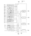
ECU500は、図3に示すように、CPU(Central Processing Unit)501、ROM(Read Only Memory)502、RAM(Random Access Memory)503、及び、バックアップRAM504などを備えている。
-ECU-
As shown in FIG. 3, the
ROM502は、各種制御プログラムや、それら各種制御プログラムを実行する際に参照されるマップ等が記憶されている。CPU501は、ROM502に記憶された各種制御プログラムやマップに基づいて各種の演算処理を実行する。また、RAM503は、CPU501での演算結果や各センサから入力されたデータ等を一時的に記憶するメモリであり、バックアップRAM504は、例えばエンジン1の停止時にその保存すべきデータ等を記憶する不揮発性のメモリである。
The
以上のCPU501、ROM502、RAM503及びバックアップRAM504は、バス507を介して互いに接続されるとともに、入力インターフェース505及び出力インターフェース506と接続されている。
The
入力インターフェース505には、クランクポジションセンサ(エンジン回転数センサ)301、カムポジションセンサ302、水温センサ303、エアフロメータ304、スロットル開度センサ305、アクセルペダルの踏み込み量に応じた検出信号を出力するアクセル開度センサ306、吸気温センサ307、インマニ圧センサ(過給圧センサ)308、空燃比センサ309、O2センサ310、筒内噴射用インジェクタ2aに供給する高圧燃料の圧力(燃圧)を検出する高圧燃料用燃圧センサ311、及び、ポート噴射用インジェクタ2bに供給する低圧燃料の圧力(燃圧)を検出する低圧燃料用燃圧センサ312などの各種センサ類が接続されている。また、入力インターフェース505にはイグニッションスイッチ313が接続されており、このイグニッションスイッチ313がオン操作されると、スタータモータ(図示せず)によるエンジン1のクランキングが開始される。
The
出力インターフェース506には、筒内噴射用インジェクタ2a、ポート噴射用インジェクタ2b、点火プラグ3のイグナイタ4、及び、スロットルバルブ5のスロットルモータ6などが接続されている。
The
そして、ECU500は、上記した各種センサの検出信号に基づいて、燃料噴射量制御(定常時の燃料噴射制御)、点火プラグ3の点火時期制御、及び、スロットルバルブ5のスロットルモータ6の駆動制御(吸入空気量制御)などを含むエンジン1の各種制御を実行する。さらに、ECU500は、下記の「加速時の燃料噴射制御」を実行する。
The
以上のECU500により実行されるプログラムによって本発明の過給機付き内燃機関(エンジン)の制御装置が実現される。
The control apparatus for the supercharged internal combustion engine (engine) according to the present invention is realized by the program executed by the
−燃料噴射量制御(定常時)−
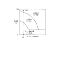
まず、ECU500のROM503には、図4に示す噴き分け率マップが記憶されている。
-Fuel injection amount control (steady state)-
First, the
図4の噴き分け率マップは、エンジン1の運転状態を示すエンジン回転数NE及び負荷率KLをパラメータとして、燃費(燃料消費率)特性や出力特性などを考慮して、燃料噴射形態を実験・シミュレーション等によって適合したマップであって、ポート噴射用インジェクタ2bのみによって燃料が噴射されるポート噴射領域(PFi領域)、ポート噴射用インジェクタ2b及び筒内噴射用インジェクタ2aによって燃料が噴射される分担領域(直噴及びポート噴射領域(PFi+DI))、及び、筒内噴射用インジェクタ2aのみによって燃料が噴射される直噴領域(DI領域)が設定されている。
In the injection ratio map of FIG. 4, the fuel injection mode is tested in consideration of fuel consumption (fuel consumption rate) characteristics and output characteristics using the engine speed NE and the load ratio KL indicating the operating state of the engine 1 as parameters. A map adapted by simulation or the like, and a port injection region (PFi region) in which fuel is injected only by the
なお、噴き分け率マップについては、エンジン回転数NE及び負荷率KL等のエンジン運転状態のパラメータに加えて、EGR量を考慮して噴き分け率を設定したマップを用いるようにしてもよい。 In addition, in addition to the engine operating state parameters such as the engine speed NE and the load factor KL, a map in which the injection ratio is set in consideration of the EGR amount may be used as the injection ratio map.
そして、ECU500は、クランクポジションセンサ301の出力信号から得られるエンジン回転数NE及びエンジン負荷率KLに基づいて、図4のマップを参照して燃料噴射の噴き分け率(筒内噴射用インジェクタ2aから噴射する燃料の分担率:Di率)R(%)を求め、その噴き分け率R及び要求噴射量に基づいて噴射時間及び噴射タイミングを算出して燃料噴射を実行する。
The
具体的には、エンジン運転状態(エンジン回転数・負荷率)が、PFi領域(噴き分け率R=0%)である場合、PFi要求噴射量、低圧燃料用燃圧センサ312の出力信号から得られる燃圧、及び、ポート噴射用インジェクタ2bの容量(流量サイズ)に基づいてポート噴射用インジェクタ2bから噴射する低圧燃料のPFi噴射時間、及び、PFi噴射タイミングを算出し、その算出したPFi噴射時間及びPFi噴射タイミングに基づいてポート噴射用インジェクタ2bを開閉制御して燃料噴射を実行する。
Specifically, when the engine operating state (engine speed / load factor) is in the PFi region (injection ratio R = 0%), it is obtained from the PFi required injection amount and the output signal of the
エンジン運転状態(エンジン回転数・負荷率)が、DI領域(噴き分け率R=100%)である場合、Di要求噴射量、高圧燃料用燃圧センサ311の出力信号から得られる燃圧、及び、筒内噴射用インジェクタ2aの容量(流量サイズ)に基づいて、筒内噴射用インジェクタ2aから噴射する高圧燃料のDI噴射時間及びDI噴射タイミングを算出し、その算出したDI噴射時間及びDI噴射タイミングに基づいて筒内噴射用インジェクタ2aを開閉制御して燃料噴射を実行する。
When the engine operating state (engine speed / load factor) is in the DI region (split ratio R = 100%), the Di required injection amount, the fuel pressure obtained from the output signal of the
エンジン運転状態(エンジン回転数・負荷率)が、分担領域(0%<噴き分け率R<100%)である場合、噴き分け率Rに基づいて筒内噴射用インジェクタ2aのDI要求噴射量(全体要求噴射量×噴き分け率R/100)と、ポート噴射用インジェクタ2bのPFi要求噴射量(全体要求噴射量×(1−噴き分け率R/100))とを求め、上記と同様にして、DI噴射時間及びDI噴射タイミングと、PFi噴射時間及びPFi噴射タイミングとを算出する。そして、その算出したDI噴射時間及びDI噴射タイミングに基づいて筒内噴射用インジェクタ2aを開閉制御するとともに、算出したPFi噴射時間及びPFi噴射タイミングに基づいてポート噴射用インジェクタ2bを開閉制御して燃料噴射を実行する。
When the engine operating state (engine speed / load factor) is in a shared region (0% <split distribution ratio R <100%), the DI required injection amount (injection amount for
ここで、上記要求噴射量は、エンジン1で燃焼された混合気の空燃比が理論空燃比となる燃料の量であって、例えば、エンジン運転状態(エンジン回転数NE及びエンジン負荷率KL)に基づいてマップ等を用いて算出することができる。また、エンジン負荷率KLは、例えば、エンジン回転速度NE、エアフロメータ304の出力信号から得られる吸入空気量、スロットル開度センサ305の出力信号から得られるスロットル開度などに基づいてマップ等を用いて算出することができる。
Here, the required injection amount is the amount of fuel in which the air-fuel ratio of the air-fuel mixture combusted in the engine 1 becomes the stoichiometric air-fuel ratio. For example, the engine injection state (engine speed NE and engine load factor KL) Based on this, it can be calculated using a map or the like. Further, the engine load factor KL uses a map or the like based on the engine speed NE, the intake air amount obtained from the output signal of the
−加速時の燃料噴射制御−
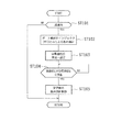
次に、ECU500が実行する加速時(エンジン1が加速される過渡時)の燃料噴射制御について図5のフローチャートを参照して説明する。図5の制御ルーチンは、ECU500において所定時間毎(例えば数msec毎)に繰り返して実行される。
-Fuel injection control during acceleration-
Next, fuel injection control performed by the
まず、ステップST101では、加速時(機関加速時)であるか否かを判定する。具体的には、例えば、アクセル開度センサ306の出力信号から得られるアクセル開度(アクセルペダルの踏み込み量)の単位時間当たりの変化量が、所定の加速判定閾値以上であるか否かを判定する。その判定結果が否定判定(NO)である場合(アクセル開度変化量<加速判定閾値である場合)はリターンする。ステップST101の判定結果が肯定判定(YES)である場合([アクセル開度変化量≧加速判定閾値]であり「加速時」と判定した場合)はステップST102に進む。
First, in step ST101, it is determined whether or not it is during acceleration (during engine acceleration). Specifically, for example, it is determined whether or not the amount of change per unit time of the accelerator opening (the amount of depression of the accelerator pedal) obtained from the output signal of the
ここで、ステップST101の判定に用いる加速判定閾値については、対象とするエンジン機種などを考慮して、実験・計算等によって適合した値を設定する。具体的には、例えば、加速判定閾値を20%/sec〜30%/secと設定して、「加速時」であるか否かを判定する。なお、この加速判定閾値はこれに限定されるものでなく、他の数値を採用してもよい。 Here, the acceleration determination threshold used for the determination in step ST101 is set to a value adapted by experiment / calculation in consideration of the target engine model. Specifically, for example, the acceleration determination threshold is set to 20% / sec to 30% / sec, and it is determined whether or not it is “acceleration”. In addition, this acceleration determination threshold value is not limited to this, You may employ | adopt another numerical value.
また、上記ステップST101での「加速時」の判定処理については、スロットル開度センサ305の出力信号から得られるスロットル開度などの他のエンジン運転状態に基づいて判定するようにしてもよいし、他の公知の手法で「加速時」を判定するようにしてもよい。
The determination process at the time of “acceleration” in step ST101 may be performed based on other engine operating conditions such as the throttle opening obtained from the output signal of the
ステップST102においては、エンジン1の運転状態に関らず、ポート噴射用インジェクタ2bからの燃料噴射(PFi噴射)のみを実行する。なお、このポート噴射用インジェクタ2bのみによる燃料噴射は、加速要求時(アクセルペダル踏み込み時:例えば図6のt1の時点)に開始する。
In step ST102, only fuel injection (PFi injection) from the
次に、ステップST103において、加速時における要求過給圧を算出する。具体的には、例えば、エンジン運転状態の1つである要求負荷(加速時のアクセルペダルの操作量(アクセル開度センサ306にて検出されるアクセル開度)に応じて決定)に基づいて、公知のマップ等を参照して目標過給圧を算出して設定する。なお、要求負荷は、アクセル開度が小さいほど小さく、アクセル開度が大きいほど大きくなる。また、目標過給圧は、要求負荷が大きいほど大きな値となる。 Next, in step ST103, a required supercharging pressure at the time of acceleration is calculated. Specifically, for example, based on a required load that is one of the engine operating states (determined according to the accelerator pedal operation amount during acceleration (accelerator opening detected by the accelerator opening sensor 306)), The target boost pressure is calculated and set with reference to a known map or the like. The required load is smaller as the accelerator opening is smaller and larger as the accelerator opening is larger. Further, the target supercharging pressure becomes a larger value as the required load is larger.
ステップST104では、インマニ圧センサ308の出力信号から現在の実過給圧を読み込み、その実過給圧が、上記ステップST103で算出した目標過給圧(加速時の目標過給圧)に到達したか否かを判定する。その判定結果が否定判定(NO)である場合(現在の実過給圧<目標過給圧である場合)は、ポート噴射用インジェクタ2bのみによる燃料噴射を継続する。このステップST104の判定処理は所定時間毎(例えば数msec毎)に繰り返して実行される。
In step ST104, the current actual boost pressure is read from the output signal of the intake
そして、ステップST104の判定結果が肯定判定(YES)となった時点、つまり、現在の実過給圧が上記目標過給圧にまで上昇した時点(過給圧が十分に立ち上った時点)で、定常時の燃料噴射制御に戻して、図4の噴き分け率マップを用いた燃料噴射制御を実行する(ステップST105)。 And when the determination result of step ST104 is affirmative (YES), that is, when the current actual boost pressure has increased to the target boost pressure (when the boost pressure has risen sufficiently), Returning to the regular fuel injection control, the fuel injection control using the injection ratio map of FIG. 4 is executed (step ST105).
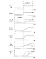
次に、この例の制御の具体的な例について、図6のタイミングチャートを参照して説明する。 Next, a specific example of the control of this example will be described with reference to the timing chart of FIG.
まず、例えば、アイドル運転状態から、図6のt1の時点でアクセルペダルが踏み込まれると(加速要求があると)、要求負荷(負荷率)がステップ状に上昇する(例えば、負荷率が100%付近にまで上昇する)。このとき、図4に示す噴き分け率マップ(定常時用)上では、エンジン運転条件がPaからPbに移行してDI領域に入る状況となり、従来制御では筒内噴射用インジェクタ2aのみによる噴射(DI噴射)が実行される。こうした状況(加速時にDI噴射のみを実行する状況)になると、スモークが発生して排気エミッションが悪化する場合がある。すなわち、筒内噴射用インジェクタ2aのみによる噴射は混合気の均質度が低いので、加速時のターボラグにより過給遅れが生じると、スモークが発生する場合がある。
First, for example, when the accelerator pedal is depressed at the time t1 in FIG. 6 from the idling state (when there is an acceleration request), the required load (load factor) increases stepwise (for example, the load factor is 100%). To the vicinity). At this time, on the injection ratio map (for steady state) shown in FIG. 4, the engine operating condition shifts from Pa to Pb and enters the DI region. In the conventional control, the injection by only the in-
このような不具合を解消するため、この例の制御では、上記した加速時のターボラグによる過給遅れを考慮して、図6に示すように、加速要求時t1から実過給圧が目標過給圧に上昇するまでの間(t1からt2までの間(過給圧が十分に立ち上るまでの間))については、ポート噴射用インジェクタ2bからの燃料噴射(PFi噴射)のみを行うようにする。このような燃料噴射により混合気の均質度が高くなって空気の利用効率が高くなるので、加速時におけるスモークの発生を抑制することが可能になる(従来制御は破線)。これによって排気エミッションの改善を図ることができる。また、混合気の均質度が高くなると燃焼状態が安定するので、図6に示すように、機関出力トルクを増大させることも可能になり(従来制御は破線)、ドライバビリティの改善を図ることができる。
In order to eliminate such a problem, in the control of this example, the supercharging delay due to the turbo lag at the time of acceleration described above is taken into consideration, as shown in FIG. Until the pressure rises (from t1 to t2 (until the boost pressure rises sufficiently)), only fuel injection (PFi injection) from the
なお、この例の制御(加速時の燃料噴射制御)は、アイドル運転状態からの加速時(アクセルペダル踏み込み時)に限られることなく、例えば、高速道路で定速運転している状態(定常運転状態)からアクセルペダルの踏み込みにより加速状態に移行した場合(図6に示す直噴領域(DI領域)に入った場合)など、他の定常運転状態からの加速の際においても、上記制御と同様に、実過給圧が目標過給圧に上昇するまでの間については、ポート噴射用インジェクタ2bからの燃料噴射のみを行うようにしてもよい。
The control (fuel injection control at the time of acceleration) in this example is not limited to the acceleration from the idling operation state (when the accelerator pedal is depressed), for example, a state in which a constant speed operation is performed on a highway (steady operation) In the case of acceleration from other steady operation states, such as when the acceleration state is entered by depressing the accelerator pedal (when entering the direct injection region (DI region) shown in FIG. 6) from the state) In addition, only the fuel injection from the
−他の実施形態−
以上の例では、4気筒ガソリンエンジンに本発明を適用した場合について説明したが、本発明はこれに限られることなく、例えば6気筒ガソリンエンジンなど他の任意の気筒数のガソリンエンジンにも適用可能である。また、直列多気筒ガソリンエンジンのほか、V型多気筒ガソリンエンジンの制御にも本発明を適用することができる。
-Other embodiments-
In the above example, the case where the present invention is applied to a four-cylinder gasoline engine has been described. It is. In addition to the in-line multi-cylinder gasoline engine, the present invention can be applied to control of a V-type multi-cylinder gasoline engine.
さらに、ガソリンエンジンに限られることなく、例えばガソリンとアルコールとを任意の割合で混合したアルコール含有燃料が使用可能なフレックス燃料内燃機関の制御にも本発明を適用することができる。 Further, the present invention is not limited to a gasoline engine, and can be applied to control of a flex-fuel internal combustion engine that can use, for example, an alcohol-containing fuel in which gasoline and alcohol are mixed at an arbitrary ratio.
本発明は、内燃機関の制御に利用可能であり、さらに詳しくは、燃焼室に吸入される空気を過給する過給機を備えた内燃機関において、加速時の燃料噴射制御に有効に利用することができる。 The present invention can be used for control of an internal combustion engine, and more specifically, is effectively used for fuel injection control during acceleration in an internal combustion engine including a supercharger that supercharges air sucked into a combustion chamber. be able to.
1 エンジン
1d 燃焼室
2a 筒内噴射用インジェクタ(筒内用燃料噴射弁)
2b ポート噴射用インジェクタ(吸気通路用燃料噴射弁)
11 吸気通路
12 排気通路
12b 排気マニホールド
100 ターボチャージャ
101 タービンホイール
102 コンプレッサインペラ
301 クランクポジションセンサ(エンジン回転数センサ)
305 スロットル開度センサ
306 アクセル開度センサ
308 インマニ圧センサ(過給圧センサ)
309 空燃比センサ
500 ECU
1
2b Injector for port injection (fuel injection valve for intake passage)
DESCRIPTION OF
305
309 Air-
Claims (3)
加速時に前記過給機による過給圧が目標過給圧に上昇するまでの間、前記吸気通路用燃料噴射弁からの燃料噴射のみを実行する燃料噴射制御手段を備えていることを特徴とする過給機付き内燃機関の制御装置。 An in-cylinder fuel injection valve that directly injects fuel into the combustion chamber, an intake passage fuel injection valve that injects fuel into the intake passage, and a supercharger that supercharges the air sucked into the combustion chamber. A control device for an internal combustion engine with a supercharger,
Fuel injection control means for performing only fuel injection from the fuel injection valve for the intake passage until the supercharging pressure by the supercharger rises to a target supercharging pressure during acceleration is provided. Control device for an internal combustion engine with a supercharger.
前記過給機にて過給された吸気の実過給圧を認識する実過給圧認識手段と、前記内燃機関の運転状態に基づいて目標過給圧を設定する目標過給圧設定手段とを備え、
前記燃料噴射制御手段は、加速時において前記実過給圧認識手段で認識される実過給圧が、前記目標過給圧設定手段にて設定される目標過給圧に上昇するまでの間、前記吸気通路用燃料噴射弁からの燃料噴射のみを実行することを特徴とする過給機付き内燃機関の制御装置。 The control device for an internal combustion engine with a supercharger according to claim 1,
Actual supercharging pressure recognition means for recognizing the actual supercharging pressure of the intake air supercharged by the supercharger, and target supercharging pressure setting means for setting a target supercharging pressure based on the operating state of the internal combustion engine; With
The fuel injection control means until the actual boost pressure recognized by the actual boost pressure recognition means during acceleration rises to the target boost pressure set by the target boost pressure setting means. A control apparatus for an internal combustion engine with a supercharger, wherein only fuel injection from the fuel injection valve for intake passage is executed.
前記実過給圧認識手段は、前記過給機の下流側の吸気通路に配置された過給圧センサであって、その過給圧センサの出力から実過給圧を認識するように構成されていることを特徴とする過給機付き内燃機関の制御装置。 The control apparatus for an internal combustion engine with a supercharger according to claim 2,
The actual supercharging pressure recognition means is a supercharging pressure sensor disposed in an intake passage on the downstream side of the supercharger, and is configured to recognize the actual supercharging pressure from the output of the supercharging pressure sensor. A control device for an internal combustion engine with a supercharger.
Priority Applications (1)
| Application Number | Priority Date | Filing Date | Title |
|---|---|---|---|
| JP2011029542A JP2012167607A (en) | 2011-02-15 | 2011-02-15 | Control apparatus for internal combustion engine with supercharger |
Applications Claiming Priority (1)
| Application Number | Priority Date | Filing Date | Title |
|---|---|---|---|
| JP2011029542A JP2012167607A (en) | 2011-02-15 | 2011-02-15 | Control apparatus for internal combustion engine with supercharger |
Publications (1)
| Publication Number | Publication Date |
|---|---|
| JP2012167607A true JP2012167607A (en) | 2012-09-06 |
Family
ID=46971984
Family Applications (1)
| Application Number | Title | Priority Date | Filing Date |
|---|---|---|---|
| JP2011029542A Withdrawn JP2012167607A (en) | 2011-02-15 | 2011-02-15 | Control apparatus for internal combustion engine with supercharger |
Country Status (1)
| Country | Link |
|---|---|
| JP (1) | JP2012167607A (en) |
Cited By (4)
| Publication number | Priority date | Publication date | Assignee | Title |
|---|---|---|---|---|
| JP2014163290A (en) * | 2013-02-25 | 2014-09-08 | Mitsubishi Motors Corp | Internal combustion engine of vehicle |
| WO2014208360A1 (en) * | 2013-06-27 | 2014-12-31 | 三菱自動車工業株式会社 | Engine control device |
| WO2014208361A1 (en) * | 2013-06-27 | 2014-12-31 | 三菱自動車工業株式会社 | Engine control device |
| JP2015010513A (en) * | 2013-06-27 | 2015-01-19 | 三菱自動車工業株式会社 | Control device for engine |
-
2011
- 2011-02-15 JP JP2011029542A patent/JP2012167607A/en not_active Withdrawn
Cited By (13)
| Publication number | Priority date | Publication date | Assignee | Title |
|---|---|---|---|---|
| JP2014163290A (en) * | 2013-02-25 | 2014-09-08 | Mitsubishi Motors Corp | Internal combustion engine of vehicle |
| WO2014208360A1 (en) * | 2013-06-27 | 2014-12-31 | 三菱自動車工業株式会社 | Engine control device |
| WO2014208361A1 (en) * | 2013-06-27 | 2014-12-31 | 三菱自動車工業株式会社 | Engine control device |
| JP2015010513A (en) * | 2013-06-27 | 2015-01-19 | 三菱自動車工業株式会社 | Control device for engine |
| JP2015010521A (en) * | 2013-06-27 | 2015-01-19 | 三菱自動車工業株式会社 | Engine control device |
| JP2015010522A (en) * | 2013-06-27 | 2015-01-19 | 三菱自動車工業株式会社 | Control device of engine |
| CN105358807A (en) * | 2013-06-27 | 2016-02-24 | 三菱自动车工业株式会社 | engine control equipment |
| CN105358806A (en) * | 2013-06-27 | 2016-02-24 | 三菱自动车工业株式会社 | engine control equipment |
| EP3015686A4 (en) * | 2013-06-27 | 2017-04-12 | Mitsubishi Jidosha Kogyo Kabushiki Kaisha | Engine control device |
| EP3015685A4 (en) * | 2013-06-27 | 2017-04-12 | Mitsubishi Jidosha Kogyo Kabushiki Kaisha | Engine control device |
| US9879617B2 (en) | 2013-06-27 | 2018-01-30 | Mitsubishi Jidosha Kogyo Kabushiki Kaisha | Control apparatus of engine |
| US9885293B2 (en) | 2013-06-27 | 2018-02-06 | Mitsubishi Jidosha Kogyo Kabushiki Kaisha | Control apparatus of engine |
| CN105358806B (en) * | 2013-06-27 | 2018-04-24 | 三菱自动车工业株式会社 | engine control equipment |
Similar Documents
| Publication | Publication Date | Title |
|---|---|---|
| KR100879486B1 (en) | engine | |
| US7532971B2 (en) | Engine control apparatus | |
| CN102852659B (en) | The control gear of direct injection engine | |
| JP5211997B2 (en) | Method and apparatus for controlling direct injection engine with turbocharger | |
| JPWO2012098644A1 (en) | Internal combustion engine with a supercharger | |
| EP3299608A2 (en) | Gasoline direct-injection compression-ignition engine for low octane fuels | |
| JP5196072B1 (en) | Control device for internal combustion engine | |
| US6513484B1 (en) | Boosted direct injection stratified charge gasoline engines | |
| JP2012167607A (en) | Control apparatus for internal combustion engine with supercharger | |
| US9556801B2 (en) | Driving force control device and driving force control method | |
| JP4134413B2 (en) | Diesel engine control device | |
| JP5229429B1 (en) | Fuel property determination device for internal combustion engine | |
| JP5093407B2 (en) | Combustion control device for internal combustion engine | |
| JP5786468B2 (en) | Control device for internal combustion engine | |
| JP2006132399A (en) | Control device and control method for supercharged engine | |
| JP2007332876A (en) | Diesel engine control device | |
| JPH10141115A (en) | Control device for in-cylinder injection internal combustion engine | |
| JP2002038990A (en) | Fuel injection device for diesel engine | |
| JP3269350B2 (en) | In-cylinder spark ignition internal combustion engine | |
| US11008970B2 (en) | Control device for engine | |
| JP3684968B2 (en) | Fuel injection device for internal combustion engine | |
| JP2007146854A (en) | In-cylinder injection engine with turbocharger and control method thereof | |
| JPH1047111A (en) | In-cylinder injection spark ignition internal combustion engine | |
| JPH1068350A (en) | Control device for in-cylinder injection internal combustion engine | |
| JPH08312402A (en) | Operation control device for internal combustion engine |
Legal Events
| Date | Code | Title | Description |
|---|---|---|---|
| A300 | Withdrawal of application because of no request for examination |
Free format text: JAPANESE INTERMEDIATE CODE: A300 Effective date: 20140513 |