JP2012166630A - Axle box support device for railroad vehicle - Google Patents
Axle box support device for railroad vehicle Download PDFInfo
- Publication number
- JP2012166630A JP2012166630A JP2011027978A JP2011027978A JP2012166630A JP 2012166630 A JP2012166630 A JP 2012166630A JP 2011027978 A JP2011027978 A JP 2011027978A JP 2011027978 A JP2011027978 A JP 2011027978A JP 2012166630 A JP2012166630 A JP 2012166630A
- Authority
- JP
- Japan
- Prior art keywords
- axle box
- fixed
- support device
- box support
- spring
- Prior art date
- Legal status (The legal status is an assumption and is not a legal conclusion. Google has not performed a legal analysis and makes no representation as to the accuracy of the status listed.)
- Granted
Links
- 241001669679 Eleotris Species 0.000 claims abstract description 53
- 238000005452 bending Methods 0.000 claims description 31
- 241000638935 Senecio crassissimus Species 0.000 claims description 13
- 239000000463 material Substances 0.000 claims description 5
- 238000006073 displacement reaction Methods 0.000 abstract description 56
- 230000001105 regulatory effect Effects 0.000 abstract description 4
- 241000270295 Serpentes Species 0.000 description 5
- 230000008878 coupling Effects 0.000 description 2
- 238000010168 coupling process Methods 0.000 description 2
- 238000005859 coupling reaction Methods 0.000 description 2
- 230000000149 penetrating effect Effects 0.000 description 1
Images


Abstract
Description
本発明は、軸箱と台車枠とを連結した軸梁の枕木方向の変位に対する剛性が変化するようにした鉄道車両用軸箱支持装置に関する。 The present invention relates to an axle box support device for a railway vehicle in which the rigidity with respect to displacement in the sleeper direction of an axle beam connecting an axle box and a carriage frame is changed.
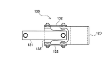
従来の鉄道車両用軸箱支持装置としては、例えば下記特許文献1に開示されたものを挙げることができる。図10は、同文献に記載された鉄道車両用軸箱支持装置を示した側面図であり、図11は、その軸梁部分を示した平面図である。この鉄道車両用軸箱支持装置(以下、単に「軸箱支持装置」とする)は、輪軸を回転可能に支持する軸箱120を有し、その軸箱120には軸バネを介して台車枠110が搭載されている。台車枠110と軸箱120とは、軸梁130によって連結されている。軸梁130は、上下一対の水平バネ131と、枕木方向に一対の垂直バネ132が連結ブロック133を介して連結されている。そして、水平バネ131は台車枠110側に固定され、垂直バネ132は軸箱120側に固定されている。
As a conventional rail car axle box support device, for example, one disclosed in
軸箱120を軸梁130によって台車枠110に連結した軸箱支持装置は、軸箱120に支持された輪軸をレール方向および枕木方向にガタ無く保持することができる。そして、走行中に生じる台車枠110と軸箱120との相対変位のうち、軸梁130の水平バネ131が上下方向変位を許容し、垂直バネ132が枕木方向変位を許容する。こうした軸箱支持装置100は、垂直バネ132が枕木方向変位を許容するため、高速走行時における枕木方向の振動に対して良好であり、摩耗部品が無いため保守が容易であるとするものである。
The axle box support device in which the
従来の軸箱支持装置は、垂直バネ132が枕木方向変位を許容することができるが、垂直バネ132の剛性が高いと曲線部の通過に際してアタック角が大きくなってしまい走行時の安定性がよくない。また、剛性が高いと細かい振動を伝達してしまうため、乗心地を悪くしてしまう。そこで、垂直バネ132の剛性を下げれば、輪軸の持つ自己操舵性によってアタック角が減少して横圧が下がり、走行安定性も高まる。しかし、輪軸蛇行動などが発生し易くなってしまい、有効な解決策ではなかった。
In the conventional axle box support device, the
本発明は、かかる課題を解決すべく、枕木方向の変位に対して剛性が変化するようにした軸梁を備える鉄道車両用軸箱支持装置を提供することを目的とする。 In order to solve such a problem, an object of the present invention is to provide a rail car axle box support device including a shaft beam whose rigidity is changed with respect to displacement in a sleeper direction.
本発明に係る鉄道車両用軸箱支持装置は、輪軸を回転可能に支持するとともに軸バネを介して台車枠を上部に搭載する軸箱と、その軸箱と台車枠とを車体のレール方向に連結する軸梁とを有するものであって、前記軸梁は、前記軸箱と台車枠とを連結する板バネによって構成され、前記軸箱及び台車枠の一方側が上下方向に固定され、他方側が枕木方向に固定され、各固定部に対して上下方向又は枕木方向に撓むものであり、前記軸梁の枕木方向の所定以上の撓みを停止させ又は枕木方向の所定以上の撓みを規制して当該撓みに対する荷重を大きくする規制手段が設けられたものであることを特徴とする。 An axle box support device for a railway vehicle according to the present invention includes an axle box that rotatably supports a wheel shaft and that has a carriage frame mounted thereon via an axle spring, and the axle box and the carriage frame in the rail direction of the vehicle body. The shaft beam is constituted by a leaf spring that connects the axle box and the carriage frame, and one side of the axle box and the carriage frame is fixed in the vertical direction, and the other side is It is fixed in the direction of sleepers and is bent in the vertical direction or the direction of sleepers with respect to each fixed part, and the bending of the axis beam in the direction of sleepers is stopped or the bending in the direction of sleepers is restricted and the bending is restricted. It is characterized in that a restricting means for increasing the load against bending is provided.
また、本発明に係る鉄道車両用軸箱支持装置は、前記軸梁が、前記軸箱側に上下方向に固定された水平部と、前記台車枠側に枕木方向に固定された垂直部と、前記水平部と垂直部が90度ずれるように捩った捩り部とを有する捩り板バネであって、前記規制手段は、前記垂直部の撓みを規制するために前記垂直部又は前記台車枠、若しくは両方に固定された当板であることが好ましい。
また、本発明に係る鉄道車両用軸箱支持装置は、前記軸梁が、前記軸箱側に上下方向に固定された水平板バネと、前記台車枠側に枕木方向に固定された垂直板バネとが車体のレール方向に連結されたものであり、前記規制手段は、前記垂直板バネの撓みを規制するために前記垂直板バネ又は前記台車枠、若しくは両方に固定された当板であることが好ましい。
Further, in the rail car axle box support device according to the present invention, the shaft beam has a horizontal part fixed in the vertical direction on the axle box side, and a vertical part fixed in the sleeper direction on the carriage frame side, A torsion leaf spring having a twisted portion twisted so that the horizontal portion and the vertical portion are shifted by 90 degrees, wherein the restricting means is configured to restrict the deflection of the vertical portion; Or it is preferable that it is the present board fixed to both.
In addition, the rail car axle box support device according to the present invention includes a horizontal leaf spring in which the shaft beam is fixed in the vertical direction on the axle box side, and a vertical leaf spring fixed in the sleeper direction on the carriage frame side. Are connected in the rail direction of the vehicle body, and the restricting means is a contact plate fixed to the vertical leaf spring or the bogie frame, or both in order to restrict the deflection of the vertical leaf spring. Is preferred.
また、本発明に係る鉄道車両用軸箱支持装置は、前記軸梁が、両端の平面部の間に湾曲部が形成された湾曲板バネと平板バネとが連結ブロックによって連結され、一対の前記湾曲板バネは、前記湾曲部が上下に広がる向きで略水平に配置され、その一端部が前記軸箱側に固定され、他端部が前記連結ブロックに固定され、一対の前記平板バネは、略垂直に配置され、その一端部が前記台車枠から下方に延びたブラケットに対し前記一対の湾曲板バネの間で連結され、他端部が前記連結ブロックに固定されたものであり、前記規制手段は、前記平板バネの撓みを規制するために前記平板バネ又は前記ブラケット、若しくは両方に固定された当板と、前記ブラケット側に固定して形成されたストッパを所定以上枕木方向へ移動しないようにした止め部とが形成されたものであることが好ましい。
また、本発明に係る鉄道車両用軸箱支持装置は、前記ブラケット側に固定して形成されたストッパが、前記湾曲板バネの撓みが所定量を超えた場合に、前記軸箱側や前記連結ブロックに当たるようにしたものであることが好ましい。
Further, in the rail car axle box support device according to the present invention, the shaft beam is formed by connecting a curved leaf spring in which a curved portion is formed between flat portions at both ends and a flat spring to each other by a coupling block. The curved leaf spring is disposed substantially horizontally in a direction in which the curved portion spreads up and down, its one end is fixed to the axle box side, the other end is fixed to the connecting block, and the pair of flat springs are It is arranged substantially vertically, one end of which is connected between the pair of curved leaf springs to a bracket extending downward from the carriage frame, and the other end is fixed to the connecting block, and the restriction The means does not move a contact plate fixed to the flat spring or the bracket, or both, and a stopper fixed to the bracket side in order to restrict the bending of the flat spring in the direction of the sleeper. Stop It is preferable that the parts and are formed.
Further, the rail car axle box support device according to the present invention is such that the stopper formed by being fixed to the bracket side has the axle box side and the connection when the bending of the curved leaf spring exceeds a predetermined amount. It is preferable that it is made to hit a block.
また、本発明に係る鉄道車両用軸箱支持装置は、前記軸梁が、両端の平面部の間に湾曲部が形成された湾曲板バネと平板バネとが連結ブロックによって連結され、一対の前記湾曲板バネは、前記湾曲部が上下に狭まる向きで略水平に配置され、その一端部が前記軸箱側に固定され、他端部が前記連結ブロックに固定され、一対の前記平板バネは、略垂直に配置され、その一端部が前記連結ブロックに固定され、他端部が前記台車枠に固定されたものであり、前記規制手段は、前記台車枠から突き出した顎部の左右両側にゴム材のストッパが固定され、前記ストッパを所定以上枕木方向へ移動しないようにした止め部が形成されたものであることが好ましい。
また、本発明に係る鉄道車両用軸箱支持装置は、前記軸梁は、前記湾曲板バネの向かい合った湾曲部に弾性部材を挟み込んだものであることが好ましい。
Further, in the rail car axle box support device according to the present invention, the shaft beam is formed by connecting a curved leaf spring in which a curved portion is formed between flat portions at both ends and a flat spring to each other by a coupling block. The curved leaf spring is disposed substantially horizontally with the curved portion narrowing up and down, one end thereof is fixed to the axle box side, the other end is fixed to the connecting block, and the pair of flat springs are The one end is fixed to the connection block and the other end is fixed to the bogie frame. The restricting means is provided with rubber on both left and right sides of the jaw protruding from the bogie frame. It is preferable that a stopper for the material is fixed and a stopper is formed to prevent the stopper from moving in the direction of the sleeper more than a predetermined amount.
In the rail car axle box support device according to the present invention, it is preferable that the shaft beam has an elastic member sandwiched between curved portions facing the curved leaf spring.
本発明では、軸箱と台車枠との間に相対的な変位が生じた場合でも、両者を連結する軸梁が各固定部に対して上下方向又は枕木方向に撓んで当該変位を許容する。その際、規制手段が、前記軸梁の枕木方向の所定以上の撓みを停止させ又は枕木方向の所定以上の撓みを規制して当該撓みに対する荷重を大きくする。そのため、例えば軸梁を構成する板バネの剛性を低くすることができるので、当初は輪軸の水平回転方向へ変位し易く曲線通過の際の自己操舵性能が良くなり、輪軸の持つ自己操舵性によってアタック角を減少することができるので、曲線走行時の横圧が低くなり走行安定性が高められる。その一方で、枕木方向については所定の撓み以降は規制手段によって剛性が高くなり、輪軸蛇行動などが発生しないようにした安定走行を可能にする。 In the present invention, even when a relative displacement occurs between the axle box and the bogie frame, the shaft beam connecting the two is deflected in the vertical direction or the sleeper direction with respect to each fixing portion to allow the displacement. At that time, the restricting means stops the bending of the shaft beam in the direction of sleepers more than a predetermined amount or restricts the bending in the direction of sleepers more than a predetermined amount to increase the load on the bending. For this reason, for example, the rigidity of the leaf spring constituting the shaft beam can be lowered, so that the self-steering performance at the time of passing through the curve is improved easily because it is easily displaced in the horizontal rotation direction of the wheel shaft. Since the attack angle can be reduced, the lateral pressure at the time of running on the curve is lowered and the running stability is improved. On the other hand, with respect to the sleeper direction, after the predetermined deflection, the rigidity is increased by the restricting means, and stable running is possible so as not to generate the wheel snake behavior.
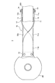
次に、本発明に係る鉄道車両用軸箱支持装置の実施形態について図面を参照しながら以下に説明する。なお、鉄道車両用軸箱支持装置を以下、単に「軸箱支持装置」とする。図1及び図2は、軸箱支持装置の第1実施形態を示した図であり、図1は平面図を、図2は側部断面図を示している。 Next, an embodiment of a rail car axle box support device according to the present invention will be described below with reference to the drawings. Hereinafter, the rail car axle box support device is simply referred to as “axle box support device”. 1 and 2 are views showing a first embodiment of the axle box support device, in which FIG. 1 is a plan view and FIG. 2 is a side sectional view.
軸箱支持装置1は、軸箱81と台車枠82とが車体のレール方向に軸梁10を介して連結されている。軸箱81の上にはバネ座83が配置され、台車枠82には側梁先端にバネ帽84が形成され、そこにバネ受85が取り付けられている。バネ座83とバネ受85との間には、二重のコイルバネが軸バネ86として入れられ、その軸バネ86は、台車枠82に対する軸箱81の上下方向の動きを吸収し、車体などの荷重バランスを調整する他、台車枠82に対する軸箱81の水平方向の動きを吸収するものである。
In the axle
軸梁10は、軸箱81の上下方向変位の他、水平方向すなわち枕木方向の首振りやレール方向の変位を許容するものであり、本実施形態では、捩られた形状の2枚の捩り板バネ11,12によって構成されている。軸箱81には固定部13が突き出し、側梁821の側面に形成された固定部14とは固定面の向きが90度ずれている。各固定部13,14と捩り板バネ11,12は、セレーションによって噛み合い、ネジ止めによって締結されている。
The
捩り板バネ11,12は、90度に捩られた捩り部11a,12aが中央部に形状され、軸箱81側には水平な平板状の水平部11b,12bが、そして台車枠82側には垂直な平板状の垂直部11c,12cが形成されている。こうした一対の捩り板バネ11,12は、互いが干渉しないように上下左右が逆になるように固定されている。
The
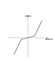
軸箱81と台車枠82との相対的な変位が上下および枕木方向に生じた場合、軸梁10は、捩り板バネ11,12の水平部11b,12bや垂直部11c,12cが撓んで上下方向及び枕木方向の変位を許容することができる。ただし、本実施形態では、側梁821の側面に当板15が固定され、捩り板バネ11,12の垂直部11c,12cに生じる撓みを抑える構成がとられている。ここで、図9は、枕木方向の変位に対する軸梁10のバネ剛性をグラフにして示した図である。
When the relative displacement between the
枕木方向への捩り板バネ11,12の撓みは、初め垂直部11c,12cの固定部14から先が撓んでいるが、当板15に当たった後は撓む寸法が短くなる。そのため、枕木方向変位に対する剛性変化は、図9に示すように、初めは変位に対する荷重が小さく剛性が低いが、戻り板バネ11,12の垂直部11c,12cが当板15に当たった後は変位に対する荷重が急激に大きくなる。本実施形態では、捩り板バネ11,12自体の剛性は低くしながらも、高い剛性が必要な変位に対して剛性が高くなるように、当板15を設けて捩り板バネ11,12が撓むよう構成されている。
The
よって、軸箱支持装置1によれば、捩り板バネ11,12の剛性が低いため、当初は輪軸の水平回転方向へ変位し易く曲線通過の際の自己操舵性能が良い。そして、輪軸の持つ自己操舵性によってアタック角を減少することができ、曲線走行時の横圧が低くなることにより走行安定性が高められる。また、細かい振動に対しても柔らかい板バネが撓むことによって振動を吸収し、乗心地を向上させることができる。その一方で、枕木方向については所定の変位以降は当板15によって変位が規制され、板バネの一部しか変位できなくなって高剛性になるため、輪軸蛇行動などが発生しないようにした安定走行を可能にする。更に、捩り板バネ11,12は、水平部11b,12bや垂直部11c,12cが上下方向及び枕木方向にそれぞれ撓んで変位を許容し、レール方向に対しても捩り部11a,12aが撓んで当該変位を許容するため、所定方向の変位を受け持つ弾性部材を取り付ける必要がなくなり、部品や部品交換が不要になる。
Therefore, according to the axle
(第2実施形態)
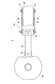
次に、図3及び図4は、第2実施形態の軸箱支持装置2を示した図であり、図3は平面図を、図4は側部断面図を示している。第1実施形態と同じ構成については同じ符号を付して説明する。本実施形態の軸箱支持装置2は、軸梁20が第1実施形態と同様に軸箱81と台車枠82との間に連結され、両者の相対的な上下方向の他、水平方向の変位を許容したものである。
(Second Embodiment)
Next, FIG.3 and FIG.4 is the figure which showed the axle
軸梁20は、長手方向に2分割され、上下に一対の板バネを略水平に配置した水平板バネ21と、枕木方向に一対の板バネを略垂直に配置した垂直板バネ22によって構成されている。軸箱81には固定部23が突き出し、上下の固定面にセレーションが形成されている。他方、台車枠82には、図示する側梁821の枕木方向の側面に固定部24が突設され、突き出した固定面にセレーションが形成されている。従って、軸箱81と台車枠82のそれぞれに形成された固定部23,24は、固定面の向きが90度ずれている。水平板バネ21と垂直板バネ22は、連結ブロック25を介して連結されている。連結ブロック25の上下左右の固定面と、水平板バネ21及び垂直板バネ22にはセレーションが形成され、噛み合った状態で締結されている。
The
軸梁20は、軸箱81と台車枠82との相対的な変位が上下方向および枕木方向に生じた場合に、水平板バネ21や垂直板バネ22が撓んで変位を許容することができる。ただし、垂直板バネ22の内側には、側梁821に当たる位置に当板26が固定され、垂直板バネ22に生じる撓みを規制する構成がとられている。枕木方向への垂直板バネ22の撓みは、初め固定部24から先が撓んでいるが、当板26が側梁821に当たった後は撓む寸法が短くなる。そのため、枕木方向変位に対する剛性変化は、図9に示すように、初めは小さいがその後は急激に大きくなる。よって、本実施形態でも、垂直板バネ22自体の剛性は低くしながらも、高い剛性が必要な変位に対して剛性が高くなるように、当板26を設けて垂直板バネ22が撓むよう構成されている。
When the relative displacement between the
本実施形態の軸箱支持装置2は、水平板バネ21や垂直板バネ22の剛性が低いため、当初は輪軸の水平回転方向へ変位し易く曲線通過の際の自己操舵性能が良い。そして、輪軸の持つ自己操舵性によってアタック角を減少することができ、曲線走行時の横圧が低くなることにより走行安定性が高められる。また、細かい振動に対しても柔らかい板バネが撓むことによって振動を吸収し、乗心地を向上させることができる。その一方で、枕木方向については所定の変位以降は当板26によって変位が規制されて高剛性になるため、輪軸蛇行動などが発生しないようにした安定走行を可能にする。また、水平板バネ21や垂直板バネ22が上下方向及び枕木方向にそれぞれ撓んで変位を許容するため、所定方向の変位を受け持つ弾性部材を取り付ける必要がなくなり、部品や部品交換が不要になる。
The axle
(第3実施形態)
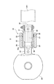
次に、図5及び図6は、第3実施形態の軸箱支持装置3を示した図であり、図5は平面図を、図6は側部断面図を示している。第1実施形態と同じ構成については同じ符号を付して説明する。本実施形態の軸箱支持装置3は、軸梁30が第1実施形態と同様に、連結した軸箱81と台車枠82との相対的な上下方向や枕木方向の変位、更にはレール方向の変位を許容したものである。
(Third embodiment)
Next, FIG.5 and FIG.6 is the figure which showed the axle
軸梁30は、2分割された構成であって、略水平に配置した上下一対の湾曲した湾曲板バネ31と、略垂直に配置した枕木方向に一対の平らな平板バネ32が連結されている。軸箱81には固定部33が突き出し、台車枠82には下方に延びた枕木方向に一対のブラケット34が形成されている。一対の湾曲板バネ31は、その一端部が軸箱81の固定部33に対してネジ止めによって締結され、他端部には連結ブロック35がネジ止めして一体になっている。湾曲板バネ31は、両端の平面部と中央の湾曲部とから構成され、上下一対の湾曲板バネ31は、図示するように中央の湾曲部が上下に広がるように取り付けられている。
The
一方、平板バネ32は、図6に示す側面側から見た場合に、上下一対の湾曲板バネ31の間に位置するように取り付けられている。平板バネ32は、連結ブロック35から軸箱方向に向けて配置され、一端部が連結ブロック35の側面にネジ止めされ、他端部は側梁821から垂れ下がったブラケット34の先端部に連結されている。一対の平板バネ32は、ブラケット34との連結部分において接続バー36によって一体になっている。
On the other hand, the
軸箱81と、台車枠82に形成されたブラケット34に対する、湾曲板バネ31と平板バネ32の固定面は90度ずれている。こうした軸梁30によれば、軸箱81と台車枠82との相対的な変位が上下方向の場合には湾曲板バネ31が撓み、枕木方向の場合には平板バネ32が撓むことにより、それぞれの変位を許容する。また、レール方向に変位が生じた場合でも、湾曲板バネ31の湾曲部が変形部分として撓むことにより、当該変位を許容する。このとき、大きな荷重によって湾曲部が押し縮められた場合、連結バー36に固定されたストッパ37が固定部33や連結ブロック35に当接し、それ以上に撓みが生じないようにして座屈が防止される。
The fixed surfaces of the
ところで、軸梁30には、平板バネ32とブラケット34に対し、それぞれ向かい合う位置に当板38が固定され、平板バネ32に生じる撓みを規制している。また、固定部33には凹部33aが形成され、そこへ連結バー36に固定されたストッパ37の先端部が入り込んでいる。従って、軸箱81と台車枠82が相対的に枕木方向に変位する場合、台車枠82側が変位すると、平板バネ32が連結ブロック35を支点に撓み、凹部33a内のストッパ37が固定部33に当たって止められる。逆に、軸箱81側が変位すると、平板バネ32は連結バー36側を支点に撓み、当板38同士が当たった後は、その当板38を支点に撓む。そのため本実施形態では、平板バネ32の剛性を低くしながらも、ストッパ37を設けて撓みを制限したり、当板38によって高い剛性が必要な変位に対して剛性が高くなるように構成されている。
By the way, the abutting
本実施形態の軸箱支持装置3は、湾曲板バネ31と平板バネ32の剛性が低いため、当初は輪軸の水平回転方向へ変位し易く、曲線通過の際の自己操舵性能が良い。そして、輪軸の持つ自己操舵性によってアタック角を減少することができ、曲線走行時の横圧が低くなることにより走行安定性が高められる。また、細かい振動に対しても柔らかい板バネが撓むことによって振動を吸収し、乗心地を向上させることができる。その一方で、枕木方向については所定の変位以降はストッパ37や当板38によって平板バネ32の撓みを抑えるため、輪軸蛇行動などが発生しないようにした安定走行を可能にする。また、湾曲板バネ31と平板バネ32が上下方向及び枕木方向にそれぞれ撓んで変位を許容し、レール方向に対しても湾曲板バネ31の湾曲部が撓んで当該変位を許容するため、所定方向の変位を受け持つ弾性部材を取り付ける必要がなくなり、部品や部品交換が不要になる。
The axle
(第4実施形態)
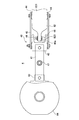
次に、図7及び図8は、第4実施形態の軸箱支持装置4を示した図であり、図7は平面図を、図8は側部断面図を示している。第1実施形態と同じ構成については同じ符号を付して説明する。本実施形態の軸箱支持装置4は、軸梁40が第1実施形態と同様に、連結した軸箱81と台車枠82との相対的な上下方向や枕木方向の変位、更にはレール方向の変位を許容したものである。
(Fourth embodiment)
Next, FIG.7 and FIG.8 is the figure which showed the axle
軸梁40は、長手方向に2分割された構成であって、略水平に配置した上下一対の湾曲した湾曲板バネ41と、略垂直に配置した枕木方向に一対の平板バネ42が連結されている。軸箱81には固定部43が突き出し、台車枠82には図示する側梁821の側面に固定部44が突設され、それぞれの固定部43,44に湾曲板バネ41と平板バネ42がネジ止めして締結されている。湾曲板バネ41と平板バネ42は90度向きを変えて配置され、両者は連結ブロック45を介して連結されている。
The
湾曲板バネ41は、両端の平面部と中央の湾曲部とから構成され、一対の湾曲板バネ41は上下対称であって、図示するように中央の湾曲部が互いに接近する向きで配置されている。上下一対の湾曲板バネ41は、間隔を狭めた湾曲部にゴム材などかなる弾性部材46が挟まれ、その上下に配置された同じゴム材などの弾性部材47とともに、上下に貫通したボルトとナットによって連結されている。湾曲板バネ41は、湾曲部の撓みによってレール方向の変位を許容するが、弾性部材46が湾曲板バネ41の過大な撓みを抑えて座屈を防止する。
The
こうした軸梁40によれば、軸箱81と台車枠82との相対的な変位が上下方向の場合には湾曲板バネ41が撓み、枕木方向の場合には平板バネ42が撓むことにより、それぞれの変位を許容する。また、レール方向に変位が生じても、湾曲板バネ41の湾曲部が変形部分として撓むことにより、当該変位を許容する。このとき、大きな荷重によって湾曲部が押し縮められる場合でも、弾性部材46が撓みを抑えて座屈を防止している。また、側梁821には、幅を狭くして軸箱81側に突き出した顎部825が形成され、そこには枕木方向の両側にゴム材からなるストッパ48が固定されている。一方、連結ブロック45には、その顎部825が入り込み、ストッパ48が枕木方向に当たるようにした凹部45aが形成されている。
According to such a
軸梁40は、軸箱81と台車枠82との相対的な変位が上下および枕木方向に生じた場合、更にレール方向に変位が生じた場合も湾曲板バネ41や平板バネ42が撓んで変位を許容することができる。ただし、平板バネ42の変位は、連結ブロック45がストッパ48に当たるまでであり、その後はストッパ48の変形によって枕木方向の変位が抑えられる。従って、図9に示す場合と同様に、初めは平板バネ42の低い剛性によって変位し、その後は変形し難くなって高い剛性で変位することになる。そのため、湾曲板バネ41や平板バネ42自体の剛性を高めることなく、枕木方向へ柔らかく撓みを生じさせるように構成されている。
When the relative displacement between the
本実施形態の軸箱支持装置4は、湾曲板バネ41や平板バネ42の剛性が低いため、当初は輪軸の水平回転方向へ変位し易く曲線通過の際の自己操舵性能が良い。そして、輪軸の持つ自己操舵性によってアタック角を減少することができ、曲線走行時の横圧が低くなることにより走行安定性が高められる。また、細かい振動に対しても柔らかい板バネが撓むことによって振動を吸収し、乗心地を向上させることができる。その一方で、枕木方向については所定の変位以降はストッパ48によって高剛性になるため、輪軸蛇行動などが発生しないようにした安定走行を可能にする。また、湾曲板バネ41や平板バネ42が上下、枕木方向及びレール方向にそれぞれ撓んで変位を許容するため、所定方向の変位を受け持つ弾性部材を取り付ける必要がなくなり、部品や部品交換が不要になる。
Since the rigidity of the
以上、本発明に係る鉄道車両用軸箱支持装置について実施形態を説明したが、本発明は、これに限定されることなく、その趣旨を逸脱しない範囲で様々な変更が可能である。
例えば、前記第1実施形態では、当板15が側梁821に固定されたものを示したが、捩りバネ11,12の垂直部11c,12cに固定されたもの、或いは両方に固定されたものであってもよい。この点については、他の実施形態についても同様である。
As mentioned above, although embodiment was described about the axle box support apparatus for rail vehicles which concerns on this invention, this invention is not limited to this, A various change is possible in the range which does not deviate from the meaning.
For example, in the first embodiment, the
1 鉄道車両用軸箱支持装置
10 軸梁
11,12 捩り板バネ
13,14 固定部
15 当板
81 軸箱
82 台車枠
DESCRIPTION OF
Claims (7)
前記軸梁は、前記軸箱と台車枠とを連結する板バネによって構成され、前記軸箱及び台車枠の一方側が上下方向に固定され、他方側が枕木方向に固定され、各固定部に対して上下方向又は枕木方向に撓むものであり、
前記軸梁の枕木方向の所定以上の撓みを停止させ又は枕木方向の所定以上の撓みを規制して当該撓みに対する荷重を大きくする規制手段が設けられたものであることを特徴とする鉄道車両用軸箱支持装置。 An axle box support for a railway vehicle that includes an axle box that rotatably supports the wheel shaft and that has a carriage frame mounted thereon via an axle spring, and an axle beam that connects the axle box and the carriage frame in the rail direction of the vehicle body. In the device
The shaft beam is configured by a leaf spring that connects the axle box and the carriage frame, one side of the axle box and the carriage frame is fixed in the vertical direction, the other side is fixed in the sleeper direction, It bends up and down or sleepers,
The railcar is characterized in that it is provided with a restricting means for stopping the bending of the shaft beam in the direction of the sleeper more than a predetermined value or restricting the bending in the direction of the sleeper more than a predetermined value to increase the load on the bending. Shaft box support device.
前記軸梁は、前記軸箱側に上下方向に固定された水平部と、前記台車枠側に枕木方向に固定された垂直部と、前記水平部と垂直部が90度ずれるように捩った捩り部とを有する捩り板バネであって、
前記規制手段は、前記垂直部の撓みを規制するために前記垂直部又は前記台車枠、若しくは両方に固定された当板であることを特徴とする鉄道車両用軸箱支持装置。 In the rail car axle box support device according to claim 1,
The shaft beam is twisted so that the horizontal part fixed in the vertical direction on the axle box side, the vertical part fixed in the sleeper direction on the cart frame side, and the horizontal part and the vertical part are shifted by 90 degrees. A torsion leaf spring having a torsion part,
The rail vehicle axle box support device according to claim 1, wherein the restricting means is a contact plate fixed to the vertical portion or the bogie frame or both to restrict the deflection of the vertical portion.
前記軸梁は、前記軸箱側に上下方向に固定された水平板バネと、前記台車枠側に枕木方向に固定された垂直板バネとが車体のレール方向に連結されたものであり、
前記規制手段は、前記垂直板バネの撓みを規制するために前記垂直板バネ又は前記台車枠、若しくは両方に固定された当板であることを特徴とする鉄道車両用軸箱支持装置。 In the rail car axle box support device according to claim 1,
The shaft beam is a horizontal leaf spring fixed in the vertical direction on the axle box side and a vertical leaf spring fixed in the sleeper direction on the carriage frame side connected in the rail direction of the vehicle body,
The rail vehicle axle box support device according to claim 1, wherein the restricting means is an abutting plate fixed to the vertical leaf spring, the bogie frame, or both to restrict the deflection of the vertical leaf spring.
前記軸梁は、両端の平面部の間に湾曲部が形成された湾曲板バネと平板バネとが連結ブロックによって連結され、一対の前記湾曲板バネは、前記湾曲部が上下に広がる向きで略水平に配置され、その一端部が前記軸箱側に固定され、他端部が前記連結ブロックに固定され、一対の前記平板バネは、略垂直に配置され、その一端部が前記台車枠から下方に延びたブラケットに対し前記一対の湾曲板バネの間で連結され、他端部が前記連結ブロックに固定されたものであり、
前記規制手段は、前記平板バネの撓みを規制するために前記平板バネ又は前記ブラケット、若しくは両方に固定された当板と、前記ブラケット側に固定して形成されたストッパを所定以上枕木方向へ移動しないようにした止め部とが形成されたものであることを特徴とする鉄道車両用軸箱支持装置。 In the rail car axle box support device according to claim 1,
In the axial beam, a curved leaf spring in which a curved portion is formed between flat portions at both ends and a flat spring are connected by a connecting block, and the pair of curved leaf springs are substantially oriented in a direction in which the curved portion extends vertically. It is horizontally arranged, one end thereof is fixed to the axle box side, the other end is fixed to the connecting block, the pair of flat springs are arranged substantially vertically, and one end thereof is below the cart frame. Connected to the bracket extending between the pair of curved leaf springs, the other end is fixed to the connection block,
The restricting means moves a contact plate fixed to the flat spring and / or the bracket, or both, and a stopper formed on the bracket side in order to limit the bending of the flat spring in the direction of the sleeper. An axle box supporting device for a railway vehicle, characterized in that a stop portion that is prevented from being formed is formed.
前記ブラケット側に固定して形成されたストッパは、前記湾曲板バネの撓みが所定量を超えた場合に、前記軸箱側や前記連結ブロックに当たるようにしたものであることを特徴とする鉄道車両用軸箱支持装置。 In the rail car axle box support device according to claim 4,
The stopper fixedly formed on the bracket side is adapted to hit the axle box side or the connecting block when the bending of the curved leaf spring exceeds a predetermined amount. Shaft box support device.
前記軸梁は、両端の平面部の間に湾曲部が形成された湾曲板バネと平板バネとが連結ブロックによって連結され、一対の前記湾曲板バネは、前記湾曲部が上下に狭まる向きで略水平に配置され、その一端部が前記軸箱側に固定され、他端部が前記連結ブロックに固定され、一対の前記平板バネは、略垂直に配置され、その一端部が前記連結ブロックに固定され、他端部が前記台車枠に固定されたものであり、
前記規制手段は、前記台車枠から突き出した顎部の左右両側にゴム材のストッパが固定され、前記ストッパを所定以上枕木方向へ移動しないようにした止め部が形成されたものであることを特徴とする鉄道車両用軸箱支持装置。 In the rail car axle box support device according to claim 1,
In the axial beam, a curved leaf spring having a curved portion formed between flat portions at both ends and a flat spring are connected by a connecting block, and the pair of curved leaf springs are substantially in a direction in which the curved portion narrows up and down. Disposed horizontally, one end thereof is fixed to the axle box side, the other end is fixed to the connection block, the pair of flat springs are disposed substantially vertically, and one end thereof is fixed to the connection block The other end is fixed to the bogie frame,
The restricting means is characterized in that rubber material stoppers are fixed on the left and right sides of the jaw portion protruding from the carriage frame, and a stopper portion is formed so as not to move the stopper in the direction of the sleeper more than a predetermined amount. An axle box support device for railway vehicles.
前記軸梁は、前記湾曲板バネの向かい合った湾曲部に弾性部材を挟み込んだものであることを特徴とする鉄道車両用軸箱支持装置。 In the rail car axle box support device according to claim 6,
The axle beam supporting device for a railway vehicle, wherein the shaft beam is obtained by sandwiching an elastic member between curved portions facing the curved leaf spring.
Priority Applications (1)
| Application Number | Priority Date | Filing Date | Title |
|---|---|---|---|
| JP2011027978A JP5734012B2 (en) | 2011-02-11 | 2011-02-11 | Rail car axle box support device |
Applications Claiming Priority (1)
| Application Number | Priority Date | Filing Date | Title |
|---|---|---|---|
| JP2011027978A JP5734012B2 (en) | 2011-02-11 | 2011-02-11 | Rail car axle box support device |
Publications (2)
| Publication Number | Publication Date |
|---|---|
| JP2012166630A true JP2012166630A (en) | 2012-09-06 |
| JP5734012B2 JP5734012B2 (en) | 2015-06-10 |
Family
ID=46971228
Family Applications (1)
| Application Number | Title | Priority Date | Filing Date |
|---|---|---|---|
| JP2011027978A Active JP5734012B2 (en) | 2011-02-11 | 2011-02-11 | Rail car axle box support device |
Country Status (1)
| Country | Link |
|---|---|
| JP (1) | JP5734012B2 (en) |
Cited By (2)
| Publication number | Priority date | Publication date | Assignee | Title |
|---|---|---|---|---|
| WO2017073002A1 (en) * | 2015-10-29 | 2017-05-04 | 川崎重工業株式会社 | Axle box support device for railroad vehicle bogie |
| FR3114292A1 (en) * | 2020-09-23 | 2022-03-25 | Alstom Transport Technologies | Railway vehicle bogie, vehicle and axle installation method thereof |
Families Citing this family (1)
| Publication number | Priority date | Publication date | Assignee | Title |
|---|---|---|---|---|
| WO2020153342A1 (en) * | 2019-01-22 | 2020-07-30 | 株式会社トクヤマ | Method for producing refined chlorosilane |
Citations (4)
| Publication number | Priority date | Publication date | Assignee | Title |
|---|---|---|---|---|
| JPS47655Y1 (en) * | 1970-03-21 | 1972-01-11 | ||
| JPS4898810U (en) * | 1972-02-26 | 1973-11-21 | ||
| JPS5338704U (en) * | 1976-09-08 | 1978-04-05 | ||
| GB2111006A (en) * | 1981-09-22 | 1983-06-29 | Maschf Augsburg Nuernberg Ag | A vehicle wheelset |
-
2011
- 2011-02-11 JP JP2011027978A patent/JP5734012B2/en active Active
Patent Citations (4)
| Publication number | Priority date | Publication date | Assignee | Title |
|---|---|---|---|---|
| JPS47655Y1 (en) * | 1970-03-21 | 1972-01-11 | ||
| JPS4898810U (en) * | 1972-02-26 | 1973-11-21 | ||
| JPS5338704U (en) * | 1976-09-08 | 1978-04-05 | ||
| GB2111006A (en) * | 1981-09-22 | 1983-06-29 | Maschf Augsburg Nuernberg Ag | A vehicle wheelset |
Cited By (5)
| Publication number | Priority date | Publication date | Assignee | Title |
|---|---|---|---|---|
| WO2017073002A1 (en) * | 2015-10-29 | 2017-05-04 | 川崎重工業株式会社 | Axle box support device for railroad vehicle bogie |
| JP2017081441A (en) * | 2015-10-29 | 2017-05-18 | 川崎重工業株式会社 | Axle box suspension for railroad vehicle truck |
| TWI607914B (en) * | 2015-10-29 | 2017-12-11 | Kawasaki Heavy Ind Ltd | Axle box supporting device for trolley for railway vehicles |
| FR3114292A1 (en) * | 2020-09-23 | 2022-03-25 | Alstom Transport Technologies | Railway vehicle bogie, vehicle and axle installation method thereof |
| EP3974283A1 (en) * | 2020-09-23 | 2022-03-30 | ALSTOM Transport Technologies | Railway vehicle bogie, associated vehicle and axle installation method |
Also Published As
| Publication number | Publication date |
|---|---|
| JP5734012B2 (en) | 2015-06-10 |
Similar Documents
| Publication | Publication Date | Title |
|---|---|---|
| KR101327576B1 (en) | Rail vehicle comprising a guide device | |
| US9352758B2 (en) | Flexible direct drive bogie | |
| JP5782617B2 (en) | Vehicle with flexible lateral connection to the vehicle | |
| US9994240B2 (en) | Chassis for rail vehicles | |
| JP6339444B2 (en) | Car body support device and railway vehicle | |
| WO2014141970A1 (en) | Guide device for guide rail-type vehicle, and guide rail-type vehicle | |
| CA2908870C (en) | Wheelset bearing for the wheelset of a rail vehicle having an internally mounted truck | |
| US20110094988A1 (en) | Heavy-duty pivot plate adjusting joint | |
| JP5734012B2 (en) | Rail car axle box support device | |
| KR20100136170A (en) | Wheel-axle set steering system of railway vehicle | |
| JP5838780B2 (en) | Steering device for steering vehicle for railway vehicles | |
| CN103241257B (en) | Anti-rolling torsion bar for railway vehicle transverse elasticity localization method and elastic thrust pad | |
| JP4838693B2 (en) | Track system | |
| JP5730052B2 (en) | Rail car axle box support device | |
| JP6309596B1 (en) | Rail car axle box support device | |
| JP6713346B2 (en) | Railcar body support device | |
| JP2013032092A (en) | Coupling device for rolling stock | |
| JP2017154559A5 (en) | ||
| JP4967358B2 (en) | Rail car axle box support device and rail car bogie | |
| RU2632035C2 (en) | Rail vehicle with antiroll bar | |
| JP2017154559A (en) | Rail type vehicle having guide device | |
| JP2009051420A (en) | Rolling restriction unit for railway vehicle hauling device | |
| JP2007182190A (en) | Mounting structure of vehicle body-truck coupling element in railway vehicle | |
| JP5126904B2 (en) | Rail car axle box support device | |
| JP6593217B2 (en) | Railway vehicle carriage and railway vehicle equipped with the carriage |
Legal Events
| Date | Code | Title | Description |
|---|---|---|---|
| A621 | Written request for application examination |
Free format text: JAPANESE INTERMEDIATE CODE: A621 Effective date: 20140116 |
|
| A977 | Report on retrieval |
Free format text: JAPANESE INTERMEDIATE CODE: A971007 Effective date: 20141016 |
|
| A131 | Notification of reasons for refusal |
Free format text: JAPANESE INTERMEDIATE CODE: A131 Effective date: 20141028 |
|
| A521 | Request for written amendment filed |
Free format text: JAPANESE INTERMEDIATE CODE: A523 Effective date: 20141208 |
|
| TRDD | Decision of grant or rejection written | ||
| A01 | Written decision to grant a patent or to grant a registration (utility model) |
Free format text: JAPANESE INTERMEDIATE CODE: A01 Effective date: 20150414 |
|
| A61 | First payment of annual fees (during grant procedure) |
Free format text: JAPANESE INTERMEDIATE CODE: A61 Effective date: 20150414 |
|
| R150 | Certificate of patent or registration of utility model |
Ref document number: 5734012 Country of ref document: JP Free format text: JAPANESE INTERMEDIATE CODE: R150 |
|
| R250 | Receipt of annual fees |
Free format text: JAPANESE INTERMEDIATE CODE: R250 |
|
| R250 | Receipt of annual fees |
Free format text: JAPANESE INTERMEDIATE CODE: R250 |
|
| R250 | Receipt of annual fees |
Free format text: JAPANESE INTERMEDIATE CODE: R250 |
|
| R250 | Receipt of annual fees |
Free format text: JAPANESE INTERMEDIATE CODE: R250 |
|
| R250 | Receipt of annual fees |
Free format text: JAPANESE INTERMEDIATE CODE: R250 |
|
| R250 | Receipt of annual fees |
Free format text: JAPANESE INTERMEDIATE CODE: R250 |