JP2012166509A - Liquid supply device and liquid injection device - Google Patents

Liquid supply device and liquid injection device Download PDF

Info

Publication number
JP2012166509A
JP2012166509A JP2011030958A JP2011030958A JP2012166509A JP 2012166509 A JP2012166509 A JP 2012166509A JP 2011030958 A JP2011030958 A JP 2011030958A JP 2011030958 A JP2011030958 A JP 2011030958A JP 2012166509 A JP2012166509 A JP 2012166509A
Authority
JP
Japan
Prior art keywords
pump chamber
ink
volume
liquid
liquid supply
Prior art date
Legal status (The legal status is an assumption and is not a legal conclusion. Google has not performed a legal analysis and makes no representation as to the accuracy of the status listed.)
Withdrawn
Application number
JP2011030958A
Other languages
Japanese (ja)
Inventor
Hitoshi Matsumoto
斉 松本
Kimitoshi Kimura
仁俊 木村
Current Assignee (The listed assignees may be inaccurate. Google has not performed a legal analysis and makes no representation or warranty as to the accuracy of the list.)
Seiko Epson Corp
Original Assignee
Seiko Epson Corp
Priority date (The priority date is an assumption and is not a legal conclusion. Google has not performed a legal analysis and makes no representation as to the accuracy of the date listed.)
Filing date
Publication date
Application filed by Seiko Epson Corp filed Critical Seiko Epson Corp
Priority to JP2011030958A priority Critical patent/JP2012166509A/en
Publication of JP2012166509A publication Critical patent/JP2012166509A/en
Withdrawn legal-status Critical Current

Links

Images

Landscapes

  • Ink Jet (AREA)

Abstract

PROBLEM TO BE SOLVED: To provide a liquid supply device which can prevent a change of liquid supply pressure caused by a change of a capacity of a pump chamber, and can stably supply liquid; and to provide a liquid injection device.SOLUTION: The liquid supply device 103 comprises: a liquid supply passage 125 which supplies the liquid to a downstream side; a pump 50 which is pump-driven by displacing a displacement member 51 so as to increase and decrease the capacity of the pump chamber 50a with a part of the liquid supply passage 125 as the pump chamber 50a; a capacity increase means 73 which displaces the displacement member 51 in a direction in which the capacity of the pump chamber 50a is increased; a capacity decrease means 70 which displaces the displacement member 51 in a direction in which the capacity of the pump chamber 50a is decreased. The capacity decrease means 70 comprises: a spring member 80 which biases the displacement member 51 in the direction in which the capacity of the pump chamber 50a is decreased; a first magnetic body 81 arranged at the displacement member 51; and a second magnetic body 82 which generates a pulling magnetic force between the first magnetic body 81 and itself.

Description

本発明は、液体供給装置、及び液体噴射装置に関するものである。   The present invention relates to a liquid supply apparatus and a liquid ejection apparatus.

従来、液体噴射ヘッドからターゲットに対して液体としてのインクを噴射させる液体噴射装置として、インクジェット式記録装置(以下、「プリンター」と称す)が広く知られている。このプリンターは、インクを収容するカートリッジから液体噴射ヘッドにインクが供給されるようになっている。例えば、下記特許文献1には、液体供給路の途中に配置したダイヤフラムポンプを収縮させることによりインクを液体噴射ヘッドに供給するようになっている。このプリンターでは、ダイヤフラムが圧縮バネで収縮した状態から該ダイヤフラムを収容する減圧室を減圧することによりダイヤフラムポンプを膨張させ、カートリッジからインクをポンプ室内に吸引し、減圧室を大気開放し、再び、圧縮バネによりダイヤフラムを収縮させることによりポンプ室内からインクを記録ヘッド側に供給することができる。   2. Description of the Related Art Conventionally, an ink jet recording apparatus (hereinafter referred to as “printer”) is widely known as a liquid ejecting apparatus that ejects ink as a liquid from a liquid ejecting head to a target. In this printer, ink is supplied from a cartridge containing ink to the liquid ejecting head. For example, in Patent Document 1 below, ink is supplied to the liquid ejecting head by contracting a diaphragm pump disposed in the middle of the liquid supply path. In this printer, the diaphragm pump is expanded by decompressing the decompression chamber containing the diaphragm from the state in which the diaphragm is contracted by the compression spring, the ink is sucked from the cartridge into the pump chamber, the decompression chamber is opened to the atmosphere, and again, Ink can be supplied from the pump chamber to the recording head side by contracting the diaphragm with the compression spring.

特開2009−160913号公報JP 2009-160913 A

しかしながら、上記従来技術では以下の問題があった。圧縮バネの発生する荷重は、圧縮バネの固定端とダイヤフラムとを押圧する他端との距離が長くなるにつれて小さくなるため、ポンプ室の容積が大きいほど押圧荷重が大きく、容積が小さくなるに従って押圧荷重が小さくなってしまい、これによりポンプ室のインク供給圧力が変化してしまうおそれがあった。そこで、インク供給圧力の下限を保持すべく圧縮バネとしてバネ荷重の大きいものを用いることも考えられるが、この場合、減圧室を減圧してダイヤフラムポンプを膨張させる際、大きいバネ荷重に抗してダイヤフラムを膨張させる必要があるため、吸引装置が大型化してしまう。また、変位によるバネ荷重の変化を小さくすべく、圧縮バネの自由長を長くすることも考えられるが、この場合、圧縮バネのダイヤフラムポンプ内への組立性が悪くなってしまう。   However, the above prior art has the following problems. The load generated by the compression spring becomes smaller as the distance between the fixed end of the compression spring and the other end that presses the diaphragm becomes longer. Therefore, the larger the pump chamber volume, the larger the pressure load. As a result, the load is reduced, which may change the ink supply pressure in the pump chamber. In order to maintain the lower limit of the ink supply pressure, it is conceivable to use a compression spring having a large spring load. In this case, when the diaphragm pump is expanded by depressurizing the decompression chamber, it resists the large spring load. Since it is necessary to inflate the diaphragm, the suction device becomes large. Further, it is conceivable to increase the free length of the compression spring in order to reduce the change in the spring load due to the displacement, but in this case, the assemblability of the compression spring into the diaphragm pump is deteriorated.

本発明はこのような事情に鑑みてなされたものであって、ポンプ室の容積変化による液体供給圧力の変化を防止し、液体を安定供給することができる液体供給装置、及び液体噴射装置を提供することを目的とする。   The present invention has been made in view of such circumstances, and provides a liquid supply device and a liquid ejection device that can prevent a change in liquid supply pressure due to a change in volume of a pump chamber and can stably supply a liquid. The purpose is to do.

上記の課題を解決するために、本発明の液体供給装置は、液体供給源側となる上流側から液体が消費される下流側に向けて前記液体を供給する液体供給流路と、該液体供給流路の一部をポンプ室として該ポンプ室の容積を増減させるように該ポンプ室の内面の少なくとも一部を構成する変位部材が変位することによりポンプ駆動するポンプと、前記ポンプ室の容積が増大する方向に前記変位部材を変位させる容積増大手段と、前記ポンプ室の容積が減少する方向に前記変位部材を変位させる容積減少手段と、を備え、前記容積減少手段が、前記変位部材の前記ポンプ室の外側に設けられ、該ポンプ室の容積を減少させる方向に該変位部材を付勢するバネ部材と、前記変位部材に設けられた第1の磁性体と、前記ポンプ室を形成するポンプ室形成部材の前記第1の磁性体と対向する位置に配置されて該第1の磁性体との間で引き合う磁力を発生させる第2の磁性体と、を備えることを特徴とする。   In order to solve the above problems, a liquid supply apparatus according to the present invention includes a liquid supply channel that supplies the liquid from an upstream side that is a liquid supply source side toward a downstream side where the liquid is consumed, and the liquid supply The displacement of a displacement member constituting at least a part of the inner surface of the pump chamber so as to increase or decrease the volume of the pump chamber with a part of the flow path as a pump chamber, and the volume of the pump chamber A volume increasing means for displacing the displacement member in an increasing direction; and a volume decreasing means for displacing the displacement member in a direction in which the volume of the pump chamber decreases. A spring member that is provided outside the pump chamber and biases the displacement member in a direction that reduces the volume of the pump chamber, a first magnetic body provided on the displacement member, and a pump that forms the pump chamber Room shape Characterized in that it comprises a second magnetic body for generating magnetic force attracting between said first magnetic body and arranged in opposing positions by the first magnetic member.

本発明の液体供給装置によれば、第1の磁性体及び第2の磁性体間で引き合う力が生じるので、ポンプ室の容積が減少するにつれて減少するバネ部材による荷重を、ポンプ室の容積が減少するにつれて増大する磁力によって補助(アシスト)することができる。よって、ポンプ室の容積変化によるバネ荷重の変化、すなわち液体の供給圧力の変化が低減され、液体供給源から下流側に液体を安定供給することができる。   According to the liquid supply apparatus of the present invention, since a pulling force is generated between the first magnetic body and the second magnetic body, the load of the spring member that decreases as the volume of the pump chamber decreases is reduced. It can be assisted by increasing magnetic force as it decreases. Therefore, a change in the spring load due to a change in the volume of the pump chamber, that is, a change in the supply pressure of the liquid is reduced, and the liquid can be stably supplied downstream from the liquid supply source.

また、上記液体供給装置においては、前記変位部材が非磁性体で形成され、前記第1の磁性体が前記変位部材の前記ポンプ室の外側に配置されているのが好ましい。
第1の磁性体及び第2の磁性体が直接接触してしまうと、吸着力が非常に大きくなるため、ポンプ室の容積を増大させるための荷重が大きくなってしまい、容積増大手段が大型化してしまう。そこで、本発明を採用すれば、第1の磁性体と第2の磁性体との間に非磁性体で形成された変位部材が配置されるので、第1の磁性体及び第2の磁性体が直接接触することで生じる上記不具合を防止できる。
In the liquid supply apparatus, it is preferable that the displacement member is formed of a non-magnetic material, and the first magnetic material is disposed outside the pump chamber of the displacement member.
If the first magnetic body and the second magnetic body are in direct contact with each other, the attracting force becomes very large, so that the load for increasing the volume of the pump chamber becomes large, and the volume increasing means becomes large. End up. Therefore, if the present invention is adopted, a displacement member formed of a non-magnetic material is disposed between the first magnetic material and the second magnetic material, so the first magnetic material and the second magnetic material. It is possible to prevent the above problems caused by direct contact.

また、上記液体供給装置においては、前記ポンプ室形成部材が非磁性体で形成され、前記第2の磁性体が前記ポンプ室形成部材の前記ポンプ室の外側に配置されているのが好ましい。
この構成によれば、第1の磁性体と第2の磁性体との間に非磁性体で形成されたポンプ室形成部材が配置されるので、第1の磁性体及び第2の磁性体が直接接触することが無く、上述のように容積増大手段が大型化するといった不具合の発生を防止できる。
In the liquid supply apparatus, it is preferable that the pump chamber forming member is formed of a non-magnetic material, and the second magnetic material is disposed outside the pump chamber of the pump chamber forming member.
According to this configuration, since the pump chamber forming member formed of a nonmagnetic material is disposed between the first magnetic material and the second magnetic material, the first magnetic material and the second magnetic material are There is no direct contact, and it is possible to prevent the occurrence of problems such as an increase in the size of the volume increasing means as described above.

また、上記液体供給装置においては、前記容積増大手段が、前記変位部材により前記ポンプ室と仕切られた減圧可能な減圧室と、該減圧室内の気体を吸引することで減圧する減圧手段と、を含むのが好ましい。
この構成によれば、減圧手段により減圧室内を減圧することで変位部材が減圧室側に変位し、ポンプ室の容積を増大させることができる。
Further, in the liquid supply device, the volume increasing means includes: a decompression chamber that can be decompressed and separated from the pump chamber by the displacement member; and a decompression means that decompresses by sucking a gas in the decompression chamber. It is preferable to include.
According to this configuration, when the decompression unit decompresses the decompression chamber, the displacement member is displaced toward the decompression chamber, and the volume of the pump chamber can be increased.

また、上記液体供給装置においては、前記第1の磁性体の変位を磁電変換素子により検出することにより前記変位部材の変位を検出する変位検出部と、該変位検出部の検出結果に基づいて前記減圧手段の駆動を制御する制御部と、を備えるのが好ましい。
この構成によれば、第1の磁性体の変位を磁電変換素子に検出することにより検出される変位部材の変位に基づいて減圧手段を駆動するタイミングを制御できるので、所望のタイミングでポンプ室の容積を増大させることができる。
In the liquid supply apparatus, the displacement detection unit detects the displacement of the displacement member by detecting the displacement of the first magnetic body by a magnetoelectric conversion element, and the detection is based on the detection result of the displacement detection unit. And a controller that controls driving of the decompression means.
According to this configuration, it is possible to control the timing of driving the decompression means based on the displacement of the displacement member detected by detecting the displacement of the first magnetic body with the magnetoelectric conversion element. The volume can be increased.

また、上記液体供給装置においては、前記ポンプ室形成部材は、前記ポンプ室の容積を減少させる方向に変位した前記変位部材に当接可能な突起部が前記ポンプ室側に形成されているのが好ましい。
この構成によれば、変位部材とポンプ室形成部材との間に突起部が介在するので、第1の磁性体と第2の磁性体とが近接し過ぎるのを防止できる。
In the liquid supply apparatus, the pump chamber forming member is formed with a protrusion on the pump chamber side that can contact the displacement member displaced in the direction of decreasing the volume of the pump chamber. preferable.
According to this configuration, since the protrusion is interposed between the displacement member and the pump chamber forming member, it is possible to prevent the first magnetic body and the second magnetic body from being too close to each other.

本発明の液体噴射装置は、液体を噴射する液体噴射ヘッドと、該液体噴射ヘッドに前記液体を供給する上記液体供給装置とを備えることを特徴とする。   According to another aspect of the invention, a liquid ejecting apparatus includes a liquid ejecting head that ejects liquid and the liquid supply device that supplies the liquid to the liquid ejecting head.

本発明の液体噴射装置によれば、上記液体供給装置を備えるため、液体供給源から下流側の液体噴射ヘッドに液体を安定供給することができ、液体噴射ヘッドから液体を良好に吐出できる信頼性の高いものとなる。   According to the liquid ejecting apparatus of the present invention, since the liquid supply apparatus is provided, the liquid can be stably supplied from the liquid supply source to the downstream liquid ejecting head, and the liquid can be discharged favorably from the liquid ejecting head. Will be expensive.

本実施形態に係るプリンターの構成を示す図。1 is a diagram illustrating a configuration of a printer according to an embodiment. インク供給構造の概略を示す図。FIG. 3 is a diagram illustrating an outline of an ink supply structure. インク供給機構の要部構成を示す図。FIG. 3 is a diagram illustrating a main configuration of an ink supply mechanism. (a),(b)は磁性体間の距離と磁力との関係に関する実験結果を示すグラフ。(A), (b) is a graph which shows the experimental result regarding the relationship between the distance between magnetic bodies, and magnetic force. ヘッドの構成を示す側断面図。FIG. 3 is a side sectional view showing a configuration of a head. ヘッドの構成を説明する要部断面図。FIG. 3 is a cross-sectional view of a main part illustrating the configuration of the head. 変形例に係るダイヤフラムポンプの構成を示した図。The figure which showed the structure of the diaphragm pump which concerns on a modification.

以下、図面を参照して、本発明の液体供給装置を含む液体噴射装置の一実施形態として、例えばインクジェット方式のプリンターを例に挙げて説明する。     Hereinafter, as an embodiment of a liquid ejecting apparatus including a liquid supply apparatus of the present invention, an ink jet printer will be described as an example with reference to the drawings.

図1に示すプリンター(液体噴射装置)1は、例えば、紙、プラスチックシートなどのシート状の媒体Mを搬送しつつ、該媒体Mにインク(液体)を噴射して所定の印刷処理を行う装置である。プリンター1は、筐体101と、媒体Mにインクを噴射するインクジェット機構102と、当該インクジェット機構102にインクを供給するインク供給機構(液体供給装置)103と、媒体Mを搬送する搬送機構104と、インクジェット機構102の保全動作を行うメンテナンス機構105と、これら各機構を制御する制御装置106とを備えている。   A printer (liquid ejecting apparatus) 1 illustrated in FIG. 1 is an apparatus that performs a predetermined printing process by ejecting ink (liquid) onto a medium M while conveying a sheet-like medium M such as paper or a plastic sheet. It is. The printer 1 includes a housing 101, an ink jet mechanism 102 that ejects ink onto the medium M, an ink supply mechanism (liquid supply device) 103 that supplies ink to the ink jet mechanism 102, and a transport mechanism 104 that transports the medium M. A maintenance mechanism 105 that performs a maintenance operation of the inkjet mechanism 102 and a control device 106 that controls these mechanisms are provided.

以下、XYZ直交座標系を設定し、当該XYZ直交座標系を適宜参照しつつ各構成要素の位置関係を説明する。本実施形態では、媒体Mの搬送方向をX方向とし、当該媒体Mの搬送面においてX方向に直交する方向をY方向とし、X軸及びY軸を含む平面に垂直な方向をZ方向と表記する。   Hereinafter, an XYZ rectangular coordinate system is set, and the positional relationship of each component will be described with reference to the XYZ rectangular coordinate system as appropriate. In this embodiment, the transport direction of the medium M is the X direction, the direction perpendicular to the X direction on the transport surface of the medium M is the Y direction, and the direction perpendicular to the plane including the X axis and the Y axis is the Z direction. To do.

筐体101は、Y方向を長手とするように形成されている。筐体101には、上記のインクジェット機構102、インク供給機構103、搬送機構104、メンテナンス機構105及び制御装置106の各部が取り付けられている。筐体101には、プラテン13が設けられている。プラテン13は、媒体Mを支持する支持部材である。プラテン13は、筐体101のうちX方向の中央部に配置されている。プラテン13は、+Z方向に向けられた平坦面13aを有している。当該平坦面13aは、媒体Mを支持する支持面として用いられる。   The casing 101 is formed so that the Y direction is the longitudinal direction. The casing 101 is provided with the above-described inkjet mechanism 102, ink supply mechanism 103, transport mechanism 104, maintenance mechanism 105, and control device 106. The casing 101 is provided with a platen 13. The platen 13 is a support member that supports the medium M. The platen 13 is disposed in the central portion of the housing 101 in the X direction. The platen 13 has a flat surface 13a oriented in the + Z direction. The flat surface 13a is used as a support surface that supports the medium M.

搬送機構104は、搬送ローラーや当該搬送ローラーを駆動するモーターなどを有している。搬送機構104は、筐体101の−X側から当該筐体101の内部に媒体Mを搬送し、当該筐体101の+X側から当該筐体101の外部に排出する。搬送機構104は、筐体101の内部において、媒体Mがプラテン13上を通過するように当該媒体Mを搬送する。搬送機構104は、制御装置106によって搬送のタイミングや搬送量などが制御されるようになっている。   The transport mechanism 104 includes a transport roller and a motor that drives the transport roller. The transport mechanism 104 transports the medium M from the −X side of the housing 101 into the housing 101 and discharges the medium M from the + X side of the housing 101 to the outside of the housing 101. The transport mechanism 104 transports the medium M so that the medium M passes over the platen 13 inside the housing 101. The transport mechanism 104 is controlled by a control device 106 such as transport timing and transport amount.

インクジェット機構102は、インクを噴射するヘッド110を含むヘッドユニット100と、当該ヘッドユニット100を保持して移動させるヘッド移動機構107とを有している。ヘッドユニット100は、ヘッド110と該ヘッド110に設けられる自己封止弁2を含む。   The ink jet mechanism 102 includes a head unit 100 including a head 110 that ejects ink, and a head moving mechanism 107 that holds and moves the head unit 100. The head unit 100 includes a head 110 and a self-sealing valve 2 provided on the head 110.

ヘッド110は、プラテン13上に送り出された媒体Mに向けてインクを噴射する。ヘッド110は、インクを噴射する噴射面(ノズル形成面)110aを有している。噴射面110aは、Z方向に向けられており、例えばプラテン13の平坦面13aに対向するように配置されている。   The head 110 ejects ink toward the medium M sent onto the platen 13. The head 110 has an ejection surface (nozzle formation surface) 110a that ejects ink. The ejection surface 110a is oriented in the Z direction, and is disposed so as to face the flat surface 13a of the platen 13, for example.

ヘッド移動機構107は、キャリッジ4を有している。ヘッド110は、当該キャリッジ4に固定されている。キャリッジ4は、筐体101の長手方向(X方向)に架けられたガイド軸8に当接されている。ヘッド110及びキャリッジ4は、プラテン13の+Z方向に配置されている。   The head moving mechanism 107 has a carriage 4. The head 110 is fixed to the carriage 4. The carriage 4 is in contact with a guide shaft 8 that extends in the longitudinal direction (X direction) of the housing 101. The head 110 and the carriage 4 are arranged in the + Z direction of the platen 13.

ヘッド移動機構107は、キャリッジ4の他、パルスモーター9と、当該パルスモーター9によって回転駆動される駆動プーリー10と、駆動プーリー10とは筐体101の幅方向の反対側に設けられた遊転プーリー11と、駆動プーリー10と遊転プーリー11との間に掛け渡されてキャリッジ4に接続されたタイミングベルト12とを有している。   In addition to the carriage 4, the head moving mechanism 107 includes a pulse motor 9, a drive pulley 10 that is rotationally driven by the pulse motor 9, and the drive pulley 10 that is provided on the opposite side in the width direction of the housing 101. A pulley 11, and a timing belt 12 that is stretched between the drive pulley 10 and the idle pulley 11 and connected to the carriage 4 are provided.

キャリッジ4は、当該タイミングベルト12に接続されている。キャリッジ4は、タイミングベルト12の回転に伴ってY方向に移動可能に設けられている。Y方向へ移動する際、キャリッジ4は、ガイド軸8によって案内されるようになっている。   The carriage 4 is connected to the timing belt 12. The carriage 4 is provided to be movable in the Y direction as the timing belt 12 rotates. When moving in the Y direction, the carriage 4 is guided by a guide shaft 8.

インク供給機構103は、インクジェット機構102のヘッド110にインク供給源としてのインクカートリッジ6に収容されているインクをヘッド110に供給するためのものである。インク供給機構103には、複数のインクカートリッジ6が収容されている。本実施形態のプリンター1は、インクカートリッジ6がヘッド110とは異なる位置に収容される構成(オフキャリッジ型)である。   The ink supply mechanism 103 is for supplying the head 110 of the inkjet mechanism 102 with the ink contained in the ink cartridge 6 as an ink supply source. A plurality of ink cartridges 6 are accommodated in the ink supply mechanism 103. The printer 1 of the present embodiment has a configuration (off-carriage type) in which the ink cartridge 6 is accommodated at a position different from the head 110.

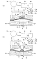
図2はプリンター1のインク供給構造の概略を示す図である。図2に示すように、インク供給機構103には、インクカートリッジ6に上流端が接続されると共に、ヘッド110に下流端が接続された状態で、インクカートリッジ6側となる上流側からヘッド110側となる下流側に向けてインクを供給するインク流路(液体供給流路)125が設けられている。   FIG. 2 is a diagram showing an outline of the ink supply structure of the printer 1. As shown in FIG. 2, the ink supply mechanism 103 has an upstream end connected to the ink cartridge 6 and a downstream end connected to the head 110 to the head 110 side from the upstream side, which is the ink cartridge 6 side. An ink flow path (liquid supply flow path) 125 for supplying ink toward the downstream side is provided.

なお、プリンター1には、そのプリンター1で使用するインクの色数(種類)に対応して複数のインク供給機構103が設けられている。なお、それらの構成は同じであるため、図2には何れか一色のインクを供給する一つのインク供給機構103をヘッド110及び一つのインクカートリッジ6と共に図示している。そして、以下においては、この図2に示す一つのインク供給機構103のインク流路125を介して上流側のインクカートリッジ6から下流側のヘッド110に向けてインクを供給する場合を例にして説明することにする。   The printer 1 is provided with a plurality of ink supply mechanisms 103 corresponding to the number of colors (types) of ink used in the printer 1. Since these configurations are the same, FIG. 2 shows one ink supply mechanism 103 that supplies ink of any one color together with the head 110 and one ink cartridge 6. In the following, an example in which ink is supplied from the upstream ink cartridge 6 toward the downstream head 110 via the ink flow path 125 of one ink supply mechanism 103 shown in FIG. 2 will be described. I will do it.

インクカートリッジ6は、内部にインクを収容するインク収容部6aと、該インク収容部6aを覆う略箱体形状のケース6bと、を備えている。また、インク収容部6aの一端側には筒部7が突出形成され、筒部7の先端にはインクを導出可能なインク供給口7aが形成されている。そして、インクカートリッジ6をインク供給機構103に接続する際には、このインク供給口7aに対してインク供給機構103からインク流路125の上流端を構成するべく突設されたインク供給針128が挿入されるようになっている。   The ink cartridge 6 includes an ink storage portion 6a that stores ink therein, and a substantially box-shaped case 6b that covers the ink storage portion 6a. Further, a cylindrical portion 7 is formed to project from one end side of the ink containing portion 6a, and an ink supply port 7a through which ink can be led out is formed at the tip of the cylindrical portion 7. When the ink cartridge 6 is connected to the ink supply mechanism 103, an ink supply needle 128 that protrudes from the ink supply mechanism 103 to form the upstream end of the ink flow path 125 with respect to the ink supply port 7a is provided. It is supposed to be inserted.

インク供給機構103は、ヘッド110を含むヘッドユニット100と、インクカートリッジ6との間を接続するインク流路125と、ダイヤフラムポンプ50と、容積減少手段70と、容積増大手段73と、を備えている。   The ink supply mechanism 103 includes a head unit 100 including the head 110, an ink flow path 125 connecting between the ink cartridges 6, a diaphragm pump 50, a volume decreasing unit 70, and a volume increasing unit 73. Yes.

インク流路125はチューブ状の樹脂材料を主体に構成されるものであり、ヘッドユニット100とダイヤフラムポンプ50との間を接続する第1のインク流路125aと、ダイヤフラムポンプ50とインクカートリッジ6との間を接続する第2のインク流路125bと、上記ダイヤフラムポンプ50内のポンプ室50aと、を含む。第1のインク流路125a及び第2のインク流路125bの構成材料としては、例えばポリプロピレンやポリエチレン等を用いることができる。   The ink flow path 125 is mainly composed of a tube-shaped resin material, and includes a first ink flow path 125 a that connects the head unit 100 and the diaphragm pump 50, the diaphragm pump 50, the ink cartridge 6, and the like. A second ink flow path 125b that connects the two, and a pump chamber 50a in the diaphragm pump 50. As a constituent material of the first ink flow path 125a and the second ink flow path 125b, for example, polypropylene or polyethylene can be used.

第1のインク流路125aの途中にはチョーク弁61が設けられている。チョーク弁61は制御装置106に電気的に接続されており、その開閉が制御されるようになっている。チョーク弁61は、第1のインク流路125aを必要に応じて閉塞することで、インクカートリッジ6からヘッド110側にインクを初期充填する場合或いはヘッド110のクリーニング時に用いられる。   A choke valve 61 is provided in the middle of the first ink flow path 125a. The choke valve 61 is electrically connected to the control device 106, and its opening and closing is controlled. The choke valve 61 is used when initially filling the ink from the ink cartridge 6 to the head 110 side or cleaning the head 110 by closing the first ink flow path 125a as necessary.

第1のインク流路125aとダイヤフラムポンプ50とは逆止弁62を介して接続されている。また、第2のインク流路125bとダイヤフラムポンプ50とは逆止弁63を介して接続されている。逆止弁62はダイヤフラムポンプ50側からヘッドユニット100側に向かってインクを流入させるとともに、ヘッドユニット100側からダイヤフラムポンプ50側へのインクの逆流を防止するためのものである。また、逆止弁63はインクカートリッジ6側からダイヤフラムポンプ50側に向かってインクを流入させるとともに、ダイヤフラムポンプ50側からインクカートリッジ6側へのインクの逆流を防止するためのものである。   The first ink flow path 125 a and the diaphragm pump 50 are connected via a check valve 62. Further, the second ink flow path 125 b and the diaphragm pump 50 are connected via a check valve 63. The check valve 62 serves to prevent ink from flowing back from the head unit 100 side to the diaphragm pump 50 side while allowing ink to flow from the diaphragm pump 50 side toward the head unit 100 side. The check valve 63 allows ink to flow from the ink cartridge 6 side toward the diaphragm pump 50 side, and prevents backflow of ink from the diaphragm pump 50 side to the ink cartridge 6 side.

ダイヤフラムポンプ50は、ダイヤフラム(変位部材)51と、インク流路125の一部を構成するポンプ室形成部材55と、該ポンプ室形成部材55及び上記ダイヤフラム51から構成される上記ポンプ室50aと、を含み、該ポンプ室50aの容積を増減させるようにダイヤフラム51を変位することによりポンプ駆動するものである。   The diaphragm pump 50 includes a diaphragm (displacement member) 51, a pump chamber forming member 55 constituting a part of the ink flow path 125, the pump chamber 50a including the pump chamber forming member 55 and the diaphragm 51, The pump 51 is driven by displacing the diaphragm 51 so as to increase or decrease the volume of the pump chamber 50a.

ダイヤフラム51は、例えばブチルゴムやフィルムで形成することができる。すなわち、本実施形態においては、ダイヤフラム51は非磁性体から構成されている。なお、フィルムを用いてダイヤフラム51を構成する場合、上記ポンプ室形成部材55と同じ非磁性体材料(上述のポリプロピレン又はポリエチレン等)で形成するのが望ましい。この場合、ダイヤフラム51とポンプ室形成部材55とを熱溶着することでポンプ室50aを構成することができる。   The diaphragm 51 can be formed of, for example, butyl rubber or a film. That is, in this embodiment, the diaphragm 51 is made of a nonmagnetic material. When the diaphragm 51 is formed using a film, it is desirable that the diaphragm 51 be formed of the same nonmagnetic material as the pump chamber forming member 55 (such as the above-described polypropylene or polyethylene). In this case, the pump chamber 50a can be configured by thermally welding the diaphragm 51 and the pump chamber forming member 55.

また、ダイヤフラム51は、上記容積減少手段70及び容積増大手段73により変位されるようになっている。容積増大手段73は、ダイヤフラムポンプ50のポンプ室50aの容積が増大する方向にダイヤフラム51を変位させるためのものである。容積増大手段73は、ダイヤフラム51によりポンプ室50aと仕切られた減圧室71と、該減圧室71を区画する減圧室形成部材34と、該減圧室形成部材34に接続される負圧発生装置(減圧手段)73aと、大気開放機構74と、を備えている。   Further, the diaphragm 51 is displaced by the volume reducing means 70 and the volume increasing means 73. The volume increasing means 73 is for displacing the diaphragm 51 in the direction in which the volume of the pump chamber 50a of the diaphragm pump 50 increases. The volume increasing means 73 includes a decompression chamber 71 partitioned from the pump chamber 50 a by the diaphragm 51, a decompression chamber forming member 34 partitioning the decompression chamber 71, and a negative pressure generating device connected to the decompression chamber forming member 34 ( Decompression means) 73a and an atmosphere release mechanism 74.

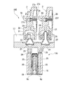
図3はインク供給機構103の要部構成を示す図である。図3に示すように、減圧室形成部材34の凹部34aには、二股に分岐した空気流路47を介して気体としての空気を吸引する吸引ポンプ等からなる負圧発生装置としての減圧ポンプ73aと大気開放機構74が接続されている。減圧ポンプ73aは、正逆回転可能な駆動モーター49が正転駆動した場合に図示しないワンウェイクラッチを介して伝達される駆動力により駆動して負圧を発生し、空気流路47を介して接続された減圧室形成部材34の凹部34a内にも同様に負圧を発生させ得るように構成されている。この構成により、減圧室形成部材34の凹部34aとダイヤフラム51とで囲み形成される容積可変の空間域は、減圧ポンプ73aの駆動に伴い負圧状態となる減圧室71として機能するようになっている。駆動モーター49は、制御装置106に電気的に接続されており、負圧発生装置73aの駆動が制御されるようになっている。   FIG. 3 is a diagram illustrating a main configuration of the ink supply mechanism 103. As shown in FIG. 3, a decompression pump 73 a as a negative pressure generating device such as a suction pump that sucks air as gas through a bifurcated air flow path 47 is provided in the recess 34 a of the decompression chamber forming member 34. And an air release mechanism 74 are connected. The decompression pump 73 a is driven by a driving force transmitted through a one-way clutch (not shown) when a forward / reverse rotation driving motor 49 is driven in a forward direction to generate a negative pressure, and is connected via an air flow path 47. Similarly, a negative pressure can be generated in the recess 34a of the decompression chamber forming member 34. With this configuration, the variable volume space region surrounded by the concave portion 34a of the decompression chamber forming member 34 and the diaphragm 51 functions as the decompression chamber 71 that becomes a negative pressure state when the decompression pump 73a is driven. Yes. The drive motor 49 is electrically connected to the control device 106, and the drive of the negative pressure generating device 73a is controlled.

一方、大気開放機構74は、大気開放孔76が形成されたボックス74d内にシール部材74aを大気開放孔76側に付設してなる大気開放弁74bが収容され、その大気開放弁74bが常にはコイルスプリング74cの付勢力により大気開放孔76を封止する閉弁方向に付勢された構成をしている。そして、大気開放機構74は、制御装置106により駆動モーター49が逆転駆動した場合に、図示しないワンウェイクラッチを介して伝達される駆動力に基づき作動するカム機構48が作動し、そのカム機構48の作動により大気開放弁74bがコイルスプリング74cの付勢力に抗して開弁方向に変位するように構成されている。すなわち、大気開放機構74は、空気流路47を介して接続された減圧室71が負圧状態になっている場合に大気開放弁74bが開弁動作することにより、その減圧室71内を大気に開放して負圧状態を解消できるようになっている。   On the other hand, the air release mechanism 74 includes an air release valve 74b in which a seal member 74a is attached to the air release hole 76 in a box 74d in which the air release hole 76 is formed. The coil spring 74c is biased in the valve closing direction for sealing the air opening hole 76 by the biasing force of the coil spring 74c. When the drive motor 49 is reversely driven by the control device 106, the air release mechanism 74 is operated by a cam mechanism 48 that operates based on a driving force transmitted through a one-way clutch (not shown). By operation, the atmosphere release valve 74b is configured to displace in the valve opening direction against the urging force of the coil spring 74c. That is, the atmosphere release mechanism 74 opens the atmosphere in the decompression chamber 71 by opening the atmosphere release valve 74b when the decompression chamber 71 connected via the air flow path 47 is in a negative pressure state. The negative pressure state can be eliminated by opening the

また、減圧室71内にはダイヤフラム51の変位を検出するための変位検出部としてのホール素子(磁電変換素子)75が設けられている。また、ホール素子75は制御装置106に電気的に接続されている。具体的にホール素子75は磁性体81の変位を検出し、該検出結果を制御装置106に送信するようになっている。制御装置106は、磁性体81の変位量からダイヤフラム51の変位量を導き、これによりポンプ室50aの容積を算出するようになっている。   In the decompression chamber 71, a hall element (magnetoelectric conversion element) 75 is provided as a displacement detector for detecting the displacement of the diaphragm 51. The hall element 75 is electrically connected to the control device 106. Specifically, the Hall element 75 detects the displacement of the magnetic body 81 and transmits the detection result to the control device 106. The controller 106 derives the displacement amount of the diaphragm 51 from the displacement amount of the magnetic body 81, and thereby calculates the volume of the pump chamber 50a.

このような構成に基づいて、容積増大手段73は、駆動モーター49を正転駆動することで減圧ポンプ73aを駆動することで減圧室71内を減圧し、ポンプ室50aに対して減圧室71を負圧とすることでダイヤフラム51をポンプ室50aの容積を増大させる方向、すなわち減圧室形成部材34側に変位させるようになっている。なお、減圧ポンプ73aとしては、後述する第1の磁性体81及び第2の磁性体82間に生じている磁力及びバネ部材50の付勢力に逆らってダイヤフラム51を変位させるだけの強さの負圧を発生させることが可能な能力のものが用いられる。   Based on such a configuration, the volume increasing means 73 depressurizes the decompression chamber 71 by driving the decompression pump 73a by driving the drive motor 49 in the normal direction, and the decompression chamber 71 with respect to the pump chamber 50a. By setting the negative pressure, the diaphragm 51 is displaced in the direction in which the volume of the pump chamber 50a is increased, that is, the decompression chamber forming member 34 side. The decompression pump 73a is a negative pressure enough to displace the diaphragm 51 against the magnetic force generated between the first magnetic body 81 and the second magnetic body 82, which will be described later, and the biasing force of the spring member 50. The one capable of generating pressure is used.

具体的に制御装置106は、ポンプ室50aの容積が下限値に到達すると該ポンプ室50a内にインクカートリッジ6側からインクを供給すべく、上記減圧ポンプ73aを駆動させるようにしている。これにより、制御装置106はポンプ室50a内にインクを供給する場合のみ減圧ポンプ73aを選択的に駆動させるので、必要以上に減圧ポンプ73aを駆動させることでプリンター1の消費電力が大きくなったり、減圧ポンプ73aのポンプの寿命を縮めてしまうといった不具合の発生を防止している。   Specifically, when the volume of the pump chamber 50a reaches the lower limit value, the control device 106 drives the decompression pump 73a to supply ink from the ink cartridge 6 side into the pump chamber 50a. As a result, the control device 106 selectively drives the decompression pump 73a only when supplying ink into the pump chamber 50a. Therefore, driving the decompression pump 73a more than necessary increases the power consumption of the printer 1. The occurrence of problems such as shortening the pump life of the decompression pump 73a is prevented.

ポンプ室50aの容積が増大するとインクカートリッジ6側から逆止弁63を介してポンプ室50a内にインクが供給されるようになっている。大気開放機構74は、ポンプ室50a内にインクを供給した後、大気開放弁74bを開弁動作することにより減圧室71内を大気に開放して負圧状態を解消するようになっている。   When the volume of the pump chamber 50a increases, ink is supplied from the ink cartridge 6 side through the check valve 63 into the pump chamber 50a. The atmosphere release mechanism 74 supplies the ink into the pump chamber 50a, and then opens the atmosphere release valve 74b, thereby opening the decompression chamber 71 to the atmosphere and eliminating the negative pressure state.

一方、容積減少手段70は、ダイヤフラムポンプ50のポンプ室50aの容積が減少する方向にダイヤフラム51を変位させるためのものである。容積減少手段70は、ダイヤフラム51のポンプ室50aの外側であって減圧室形成部材34の凹部34a内に設けられたバネ部材50と、第1の磁性体81と、第2の磁性体82と、を含む。   On the other hand, the volume reducing means 70 is for displacing the diaphragm 51 in the direction in which the volume of the pump chamber 50a of the diaphragm pump 50 decreases. The volume reducing means 70 includes a spring member 50 provided outside the pump chamber 50a of the diaphragm 51 and in the recess 34a of the decompression chamber forming member 34, a first magnetic body 81, and a second magnetic body 82. ,including.

バネ部材50は一端がダイヤフラム51に固定されており、他端が上記凹部34aに固定されている。バネ部材50は例えば圧縮バネから構成されており、弾性変形した状態で取り付けられている。そのため、バネ部材50はポンプ室50aの容量を減少する方向にダイヤフラム51を付勢した状態に取り付けられている。   One end of the spring member 50 is fixed to the diaphragm 51, and the other end is fixed to the recess 34a. The spring member 50 is composed of a compression spring, for example, and is attached in an elastically deformed state. Therefore, the spring member 50 is attached in a state in which the diaphragm 51 is urged in a direction to reduce the capacity of the pump chamber 50a.

第1の磁性体81は、ダイヤフラム51におけるポンプ室50aの外側に配置されている。一方、第2の磁性体82は、ポンプ室形成部材55のポンプ室50aの外側であって第1の磁性体81と対向する位置に配置されている。第1の磁性体81と第2の磁性体82との間には、互いが引き合う磁力が発生するようになっている。本実施形態では、第1の磁性体81が磁石から構成されており、第2の磁性体82が金属板から構成されている。なお、第1の磁性体81及び第2の磁性体82の組み合わせとして採用可能な材料は、これらに限られない。すなわち、第1の磁性体81と第2の磁性体82とは互いが引き合う磁力を発生させるもの同士であれば種々の磁性材料(一方が金属で他方が磁石の場合、或いは両方が磁石の場合を含む)を用いることができる。   The first magnetic body 81 is disposed outside the pump chamber 50 a in the diaphragm 51. On the other hand, the second magnetic body 82 is disposed outside the pump chamber 50 a of the pump chamber forming member 55 and at a position facing the first magnetic body 81. A magnetic force attracting each other is generated between the first magnetic body 81 and the second magnetic body 82. In this embodiment, the 1st magnetic body 81 is comprised from the magnet, and the 2nd magnetic body 82 is comprised from the metal plate. Note that materials that can be used as the combination of the first magnetic body 81 and the second magnetic body 82 are not limited to these. That is, as long as the first magnetic body 81 and the second magnetic body 82 can generate magnetic forces attracting each other, various magnetic materials (one is a metal and the other is a magnet, or both are magnets) Can be used.

ところで、ダイヤフラム51に取り付けられたバネ部材50は、ポンプ室50aの容積が減少するに従って自由長に近づくため、付勢力が減少してくる。すると、バネ部材50によるダイヤフラム51を圧縮する力、すなわちポンプ室50aからヘッド110側に送られるインクの供給圧力が低下しまうおそれがある。インクの供給圧力が低下するとヘッド110にインクを安定供給することが難しくなる。   Incidentally, since the spring member 50 attached to the diaphragm 51 approaches the free length as the volume of the pump chamber 50a decreases, the urging force decreases. Then, there is a possibility that the force for compressing the diaphragm 51 by the spring member 50, that is, the supply pressure of the ink sent from the pump chamber 50a to the head 110 side is lowered. When the ink supply pressure decreases, it becomes difficult to stably supply ink to the head 110.

これに対し、本実施形態に係る容積減少手段70は、ダイヤフラム51が圧縮されてポンプ室50aの容量が小さくなるに従って接近した第1の磁性体81及び第2の磁性体82間で生じる引き合う力(磁力)を利用し、バネ部材50が伸びるに従って減少していく付勢力を補助(アシスト)するようにしている。これにより、ダイヤフラムポンプ50は、上記容積減少手段70の作用により、ダイヤフラム51を安定した力で圧縮することができ、ポンプ室50a内のインクをヘッドユニット100(ヘッド110)側に供給することができるようになっている。   On the other hand, the volume reducing means 70 according to the present embodiment has an attractive force generated between the first magnetic body 81 and the second magnetic body 82 that approach each other as the diaphragm 51 is compressed and the capacity of the pump chamber 50a decreases. (Magnetic force) is used to assist (assist) a biasing force that decreases as the spring member 50 extends. As a result, the diaphragm pump 50 can compress the diaphragm 51 with a stable force by the action of the volume reducing means 70, and supply the ink in the pump chamber 50a to the head unit 100 (head 110) side. It can be done.

ここで、上述した第1の磁性体81及び第2の磁性体82間に発生する磁力は後述の実験結果に示されるように両磁性体81,82間の距離によって変化する。図4は磁性体間の距離と磁力との関係に関する実験結果を示すグラフであり、具体的に同図(a)は空間磁束密度と磁性体間の距離との関係を示し、同図(b)は磁性体間の距離と吸引力(磁力)との関係を示している。なお、本実験では一方の磁性体としてφ20×10mmのネオジム磁石を用い、他方の磁性体として鉄板を用い、両者の距離を変化させた際、両者の間に生じる磁力(吸引力)及び空間磁束密度の変化について測定した。   Here, the magnetic force generated between the first magnetic body 81 and the second magnetic body 82 described above varies depending on the distance between the two magnetic bodies 81 and 82 as shown in the experimental results described later. FIG. 4 is a graph showing experimental results regarding the relationship between the distance between the magnetic bodies and the magnetic force. Specifically, FIG. 4A shows the relation between the spatial magnetic flux density and the distance between the magnetic bodies, and FIG. ) Shows the relationship between the distance between magnetic bodies and the attractive force (magnetic force). In this experiment, a φ20 × 10 mm neodymium magnet is used as one magnetic body, and an iron plate is used as the other magnetic body. When the distance between the two is changed, the magnetic force (attraction force) and spatial magnetic flux generated between the two are changed. The change in density was measured.

図4(a)、(b)に示すように、磁石及び鉄板間の距離が大きくなると、空間磁束密度及び磁力が低下することが確認できる。また、磁石及び鉄板間の距離が0の場合、すなわち磁石及び鉄板が接触している場合、空間磁束密度及び磁力が最大となることが確認できる。   As shown in FIGS. 4A and 4B, it can be confirmed that the spatial magnetic flux density and the magnetic force decrease as the distance between the magnet and the iron plate increases. Moreover, when the distance between a magnet and an iron plate is 0, ie, when a magnet and an iron plate are contacting, it can confirm that space magnetic flux density and magnetic force become the maximum.

上述の結果に示されるように、ポンプ室50aの容積を最小とする位置までダイヤフラム51が移動した際、第1の磁性体81及び第2の磁性体82間の距離が近すぎると、両者81,82間に生じる磁力が強くなってしまう。容積増大手段73の減圧ポンプ73aは、第1の磁性体81及び第2の磁性体82間に生じている強い磁力に逆らってダイヤフラム51をポンプ室50aの容積を増大させる方向に変位させる必要があるため、大容量のものを採用する必要が生じてしまう。減圧ポンプ73aとして負圧発生能力の高いものを採用するとプリンター1のコストが嵩むため好ましくない。   As shown in the above results, when the diaphragm 51 moves to a position where the volume of the pump chamber 50a is minimized, if the distance between the first magnetic body 81 and the second magnetic body 82 is too close, both 81 , 82 becomes stronger. The decompression pump 73a of the volume increasing means 73 needs to displace the diaphragm 51 in the direction of increasing the volume of the pump chamber 50a against the strong magnetic force generated between the first magnetic body 81 and the second magnetic body 82. Therefore, it becomes necessary to adopt a large capacity. If a vacuum pump 73a having a high negative pressure generation capability is used, the cost of the printer 1 increases, which is not preferable.

そこで、本実施形態では、容量の小さい減圧ポンプ73aがダイヤフラム51を移動させることができるように、ポンプ室50aの容積が最小となった際、磁力が大きくなりすぎない位置に第1の磁性体81及び第2の磁性体82を配置させるようにしている。これにより、減圧ポンプ73aが大型化することでプリンター1のコストが嵩むのを防止している。   Therefore, in the present embodiment, the first magnetic body is located at a position where the magnetic force does not become too large when the volume of the pump chamber 50a is minimized so that the vacuum pump 73a having a small capacity can move the diaphragm 51. 81 and the second magnetic body 82 are arranged. This prevents the cost of the printer 1 from increasing due to an increase in the size of the decompression pump 73a.

具体的には、図2、3に示したように第1の磁性体81及び第2の磁性体82をいずれもポンプ室50aの外側に配置している。これにより、ポンプ室50aの容積が最小となった場合においても、第1の磁性体81及び第2の磁性体82間に非磁性体材料で形成されるダイヤフラム51及びポンプ室形成部材55が介在することで第1の磁性体81及び第2の磁性体82同士が直接接触してしまうことを防止している。   Specifically, as shown in FIGS. 2 and 3, both the first magnetic body 81 and the second magnetic body 82 are disposed outside the pump chamber 50a. Thereby, even when the volume of the pump chamber 50a is minimized, the diaphragm 51 and the pump chamber forming member 55 formed of the nonmagnetic material are interposed between the first magnetic body 81 and the second magnetic body 82. This prevents the first magnetic body 81 and the second magnetic body 82 from coming into direct contact with each other.

メンテナンス機構105は、ヘッド110の噴射面110aを払拭するワイピング機構111と、当該噴射面110aを覆うキャッピング機構112と、を有している。キャッピング機構112は、ヘッド110の噴射面110aを覆いつつ当該噴射面110a上の空間を吸引することでノズルNZ(図5,6参照)からインクを排出させる吸引動作時に用いられる吸引用キャップ部112aを有している。   The maintenance mechanism 105 includes a wiping mechanism 111 that wipes the ejection surface 110a of the head 110, and a capping mechanism 112 that covers the ejection surface 110a. The capping mechanism 112 covers the ejection surface 110a of the head 110 and sucks the space on the ejection surface 110a, thereby sucking the ink from the nozzles NZ (see FIGS. 5 and 6). have.

吸引用キャップ部112aには、吸引ポンプなどの吸引機構113が接続されており、内部にインク吸収部材114が設けられている。吸引用キャップ部112aは、吸引機構113により、噴射面110aを覆いつつ当該噴射面110aとの間に生じる内部空間を吸引できるようになっている。ヘッド110から吸引機構113側に排出された廃インクは、廃インク回収機構115において回収されるようになっている。   A suction mechanism 113 such as a suction pump is connected to the suction cap portion 112a, and an ink absorbing member 114 is provided inside. The suction cap portion 112a can suck the internal space generated between the suction cap 110a and the ejection surface 110a while covering the ejection surface 110a. The waste ink discharged from the head 110 to the suction mechanism 113 side is collected by the waste ink collection mechanism 115.

また、メンテナンス機構105は、図1に示したように、ヘッド110のホームポジションに配置されている。このホームポジションは、媒体Mに対して印刷が行われる領域から外れた領域に設定されている。本実施形態では、プラテン13の+Y側にホームポジションが設定されている。ホームポジションは、例えばプリンター1の電源がオフである時や長時間に亘って記録が行われない時、或いはメンテナス作業を行う際にヘッド110が待機する場所である。   In addition, the maintenance mechanism 105 is disposed at the home position of the head 110 as shown in FIG. This home position is set in an area outside the area where printing is performed on the medium M. In the present embodiment, the home position is set on the + Y side of the platen 13. The home position is a place where the head 110 waits when the printer 1 is turned off, when recording is not performed for a long time, or when maintenance work is performed.

図5は、ヘッドユニット100の構成を示す側断面図である。図6は、ヘッド110の構成を説明する要部断面図である。図5,6に示されるように、ヘッド110は、導入針ユニット17、ヘッドケース18、流路ユニット19及びアクチュエータユニット20を備えている。   FIG. 5 is a side sectional view showing the configuration of the head unit 100. FIG. 6 is a cross-sectional view of a main part for explaining the configuration of the head 110. As shown in FIGS. 5 and 6, the head 110 includes an introduction needle unit 17, a head case 18, a flow path unit 19, and an actuator unit 20.

導入針ユニット17の上面には、フィルター21を介在させた状態で2本のインク導入針22が並んで取り付けられている。導入針ユニット17の内部には、各インク導入針22に対応したインク導入路23が形成されている。インク導入路23の上端は、フィルター21を介してインク導入針22に接続されている。インク導入路23の下端は、パッキン24を介してヘッドケース18内部のケース流路25に接続されている。インク導入針22には、それぞれ自己封止弁2が装着されている。   Two ink introduction needles 22 are mounted side by side on the upper surface of the introduction needle unit 17 with the filter 21 interposed. An ink introduction path 23 corresponding to each ink introduction needle 22 is formed inside the introduction needle unit 17. The upper end of the ink introduction path 23 is connected to the ink introduction needle 22 through the filter 21. The lower end of the ink introduction path 23 is connected to a case flow path 25 inside the head case 18 via a packing 24. A self-sealing valve 2 is attached to each ink introduction needle 22.

自己封止弁2は、例えばポリプロピレン等の樹脂製材料を用いて形成されている。自己封止弁2には、インク室27が設けられている。インク室27は、例えばすり鉢状に形成された凹部27aを有している。凹部27aは、開口部27bを有している。開口部27bには、透明な弾性シート26が貼り付けられている。凹部27aの底部には、連通孔27cが形成されている。連通孔27cは、インク室27の凹部27aとインク供給室27dとの間を連通するように形成されている。インク供給室27dは、インク流路125に接続されている。インク供給室27dのうちインク流路125との接続部分には、例えば不図示のフィルタなどが設けられている。   The self-sealing valve 2 is formed using a resin material such as polypropylene, for example. The self-sealing valve 2 is provided with an ink chamber 27. The ink chamber 27 has a concave portion 27a formed in a mortar shape, for example. The recess 27a has an opening 27b. A transparent elastic sheet 26 is attached to the opening 27b. A communication hole 27c is formed at the bottom of the recess 27a. The communication hole 27c is formed to communicate between the recess 27a of the ink chamber 27 and the ink supply chamber 27d. The ink supply chamber 27d is connected to the ink flow path 125. For example, a filter (not shown) is provided at a portion of the ink supply chamber 27d connected to the ink flow path 125.

弾性シート26は、開口部27bを塞ぐように貼り付けられている。弾性シート26は、インク室27の圧力に応じて変位するようになっている。弾性シート26は、例えば後述する付勢部材27fの付勢力によってインク室27の容積が増加する方向に付勢力を受け、凹部27aの外側へ向けて突出した状態となっており、インク室27の圧力が外部の圧力よりも低い所定の圧力になるとインク室27の容積が減少する方向に変位する。   The elastic sheet 26 is stuck so as to close the opening 27b. The elastic sheet 26 is displaced according to the pressure in the ink chamber 27. The elastic sheet 26 receives a biasing force in a direction in which the volume of the ink chamber 27 increases due to a biasing force of a biasing member 27f described later, for example, and protrudes toward the outside of the recess 27a. When the pressure reaches a predetermined pressure lower than the external pressure, the volume of the ink chamber 27 is displaced in a decreasing direction.

弾性シート26には、弁27eが取り付けられている。弁27eは、凹部27aから連通孔27cを介してインク供給室27dに接続されており、インク供給室27d側から連通孔27cを開閉するように形成されている。弁27eは、弾性シート26のインク室の容積が増減による変位に連動して連通孔27cを開閉するようになっている。具体的には、インク室27の容積が減少する方向に弾性シート26が変位したときに連通孔27cが開状態となり、インク室27の容積が増加する方向に弾性シート26が変位したときには連通孔27cが閉状態となる。弁27eの弾性シート26側の端部には、所定の付勢力を付与する付勢部材27fが取り付けられており、その付勢力により弾性シート26がインク室27の容積が減少する方向に変位して連通孔27cが開状態となるインク室27の外部の圧力より低い所定の圧力が設定されている。   A valve 27 e is attached to the elastic sheet 26. The valve 27e is connected to the ink supply chamber 27d from the recess 27a through the communication hole 27c, and is formed to open and close the communication hole 27c from the ink supply chamber 27d side. The valve 27e opens and closes the communication hole 27c in conjunction with a displacement caused by an increase or decrease in the volume of the ink chamber of the elastic sheet 26. Specifically, the communication hole 27c is opened when the elastic sheet 26 is displaced in a direction in which the volume of the ink chamber 27 decreases, and the communication hole is opened when the elastic sheet 26 is displaced in a direction in which the volume of the ink chamber 27 increases. 27c is closed. An urging member 27f that applies a predetermined urging force is attached to an end of the valve 27e on the elastic sheet 26 side, and the urging force causes the elastic sheet 26 to be displaced in a direction in which the volume of the ink chamber 27 decreases. Thus, a predetermined pressure lower than the pressure outside the ink chamber 27 where the communication hole 27c is opened is set.

自己封止弁2は、針接続部28に接続されている。針接続部28は、インク導入針22自己封止弁2とインク導入針22とを接続する部分である。インク室27の凹部27aには、当該針接続部28に接続される接続流路29が形成されている。針接続部28の内部空間には、インク導入針22がほぼ隙間無く嵌め込まれるシール材31が設けられている。インク導入針22がシール材31に嵌め込まれることで、自己封止弁2と導入針ユニット17との間がほぼ漏れの無い状態で接続されるようになっている。   The self-sealing valve 2 is connected to the needle connection portion 28. The needle connecting portion 28 is a portion that connects the ink introduction needle 22 self-sealing valve 2 and the ink introduction needle 22. In the concave portion 27 a of the ink chamber 27, a connection channel 29 connected to the needle connection portion 28 is formed. A seal material 31 into which the ink introduction needle 22 is fitted with almost no gap is provided in the internal space of the needle connection portion 28. The ink introduction needle 22 is fitted into the sealing material 31 so that the self-sealing valve 2 and the introduction needle unit 17 are connected with almost no leakage.

図5に示すように、ヘッドケース18は、合成樹脂などを用いて形成されている。ヘッドケース18は、例えば中空部を有するように箱型に形成されている。ヘッドケース18は、上端側がパッキン24を介して導入針ユニット17を取り付けられている。ヘッドケース18の下端面には、流路ユニット19が接合されている。ヘッドケース18の内部に形成された中空部37内には、アクチュエータユニット20が収容されている。   As shown in FIG. 5, the head case 18 is formed using a synthetic resin or the like. The head case 18 is formed in a box shape so as to have a hollow portion, for example. The head case 18 has an introduction needle unit 17 attached to the upper end side via a packing 24. A flow path unit 19 is joined to the lower end surface of the head case 18. The actuator unit 20 is accommodated in a hollow portion 37 formed inside the head case 18.

ヘッドケース18の内部には、高さ方向を貫通してケース流路25が設けられている。
ケース流路25の上端は、パッキン24を介して導入針ユニット17のインク導入路23に連通されている。ケース流路25の下端は、流路ユニット19内の共通インク室44に連通されている。このため、インク導入針22から導入されたインクは、インク導入路23及びケース流路25を通じて共通インク室44側に供給されるようになっている。
A case channel 25 is provided inside the head case 18 so as to penetrate the height direction.
The upper end of the case flow path 25 communicates with the ink introduction path 23 of the introduction needle unit 17 through the packing 24. The lower end of the case flow path 25 communicates with the common ink chamber 44 in the flow path unit 19. Therefore, the ink introduced from the ink introduction needle 22 is supplied to the common ink chamber 44 side through the ink introduction path 23 and the case flow path 25.

アクチュエータユニット20は、例えば櫛歯状に配置された複数の圧電振動子38と、当該圧電振動子38を保持する固定板39と、圧電振動子38に対して制御装置106からの駆動信号を供給するフレキシブルケーブル40とを有している。   The actuator unit 20 supplies, for example, a plurality of piezoelectric vibrators 38 arranged in a comb shape, a fixed plate 39 that holds the piezoelectric vibrator 38, and a drive signal from the control device 106 to the piezoelectric vibrator 38. And a flexible cable 40.

圧電振動子38は、図中下側端部が固定板39の下端面から突出するように固定されている。このように、各圧電振動子38は、所謂片持ち梁の状態で固定板39上に取り付けられている。各圧電振動子38を支持する固定板39は、例えば厚さ1mm程度のステンレス鋼によって構成されている。固定板39のうち圧電振動子38の固定された面とは異なる面が中空部37を区画するケース内壁面に接着されている。   The piezoelectric vibrator 38 is fixed so that the lower end portion in the figure protrudes from the lower end surface of the fixed plate 39. Thus, each piezoelectric vibrator 38 is mounted on the fixed plate 39 in a so-called cantilever state. The fixed plate 39 that supports each piezoelectric vibrator 38 is made of, for example, stainless steel having a thickness of about 1 mm. A surface of the fixing plate 39 different from the surface on which the piezoelectric vibrator 38 is fixed is bonded to the inner wall surface of the case that defines the hollow portion 37.

流路ユニット19は、振動板41、流路基板42及びノズル基板43を有している。振動板41、流路基板42及びノズル基板43は、積層された状態で接着されている。流路ユニット19は、共通インク室44からインク供給口45、圧力室46を通り、ノズルNZに至るまでの一連のインク流路(液体流路)を構成している。圧力室46は、ノズルNZの配列方向(ノズル列方向)に対して直交する方向が長手方向となるように形成されている。   The flow path unit 19 includes a vibration plate 41, a flow path substrate 42 and a nozzle substrate 43. The diaphragm 41, the flow path substrate 42, and the nozzle substrate 43 are bonded in a stacked state. The flow path unit 19 constitutes a series of ink flow paths (liquid flow paths) from the common ink chamber 44 through the ink supply port 45 and the pressure chamber 46 to the nozzle NZ. The pressure chamber 46 is formed such that the direction perpendicular to the arrangement direction (nozzle row direction) of the nozzles NZ is the longitudinal direction.

共通インク室44は、ケース流路25に接続されている。共通インク室44には、インク導入針22側からのインクが導入される室である。また、共通インク室44は、インク供給口45に接続されている。共通インク室44に導入されたインクは、当該インク供給口45を通じて各圧力室46に分配されるようになっている。   The common ink chamber 44 is connected to the case flow path 25. The common ink chamber 44 is a chamber into which ink from the ink introduction needle 22 side is introduced. The common ink chamber 44 is connected to the ink supply port 45. The ink introduced into the common ink chamber 44 is distributed to each pressure chamber 46 through the ink supply port 45.

ノズル基板43は、流路ユニット19の底部に配置されている。ノズル基板43には、媒体Mに形成される画像などのドット形成密度に対応したピッチ(例えば180dpi)で複数のノズルNZが形成されている。ノズル基板43としては、例えばステンレス鋼などの金属製の板材が用いられる。   The nozzle substrate 43 is disposed at the bottom of the flow path unit 19. A plurality of nozzles NZ are formed on the nozzle substrate 43 at a pitch (for example, 180 dpi) corresponding to the dot formation density of an image or the like formed on the medium M. As the nozzle substrate 43, for example, a metal plate material such as stainless steel is used.

このような構成のヘッド110では、ケース流路25から共通インク室44及び圧力室46を通ってノズルNZに至る一連のインク流路が形成されている。上記の圧電振動子を素子長手方向に伸縮させると振動板41が変形し、圧力室46の容積が変化する。これにより、圧力室46内のインク圧力が変化する。そして、この圧力室46内のインク圧力の変化を利用することで、ノズルNZからインク滴を吐出させることができる。   In the head 110 having such a configuration, a series of ink flow paths are formed from the case flow path 25 through the common ink chamber 44 and the pressure chamber 46 to the nozzle NZ. When the piezoelectric vibrator is expanded and contracted in the longitudinal direction of the element, the vibration plate 41 is deformed and the volume of the pressure chamber 46 is changed. Thereby, the ink pressure in the pressure chamber 46 changes. Ink droplets can be ejected from the nozzles NZ by utilizing the change in ink pressure in the pressure chamber 46.

次に、上記プリンター1の動作として本発明の特徴部分であるインク供給機構103の動作を主体に説明する。プリンター1は、チョーク弁61を閉塞した状態で行われるインクの初期充填動作により、インクカートリッジ6からヘッドユニット100のヘッド110にインクが充填された状態となっている。   Next, the operation of the ink supply mechanism 103, which is a characteristic part of the present invention, will be mainly described as the operation of the printer 1. The printer 1 is in a state where ink is filled from the ink cartridge 6 to the head 110 of the head unit 100 by the initial ink filling operation performed with the choke valve 61 closed.

プリンター1は、圧電振動子38に駆動信号を入力し、圧電振動子38を伸縮させることで圧力室46の容積を変化させ、インクを収容した圧力室46の圧力を変動させる。この圧力の変動によって、ノズルNZからインクが噴射される。ノズルNZからインクが噴射されると自己封止弁2のインク室27の容積が減少する。このとき、弾性シート26が弁27eが開く方向に変位することで第1のインク流路125aを介してインク室27内にインクが補充される。   The printer 1 inputs a drive signal to the piezoelectric vibrator 38 and expands / contracts the piezoelectric vibrator 38 to change the volume of the pressure chamber 46 and to change the pressure of the pressure chamber 46 containing ink. Ink is ejected from the nozzle NZ due to the fluctuation of the pressure. When ink is ejected from the nozzle NZ, the volume of the ink chamber 27 of the self-sealing valve 2 decreases. At this time, the elastic sheet 26 is displaced in the direction in which the valve 27e opens, so that the ink is replenished into the ink chamber 27 via the first ink flow path 125a.

このとき、ダイヤフラムポンプ50は、ダイヤフラム51がポンプ室50aの容積を減少させる方向に変位し、第1のインク流路125aを介してヘッドユニット100(自己封止弁2)にインクを供給する。ノズルNZからインクが噴射されるに従って、ポンプ室50aは内部に収容されているインクが無くなるまで容積が減少し続ける。   At this time, the diaphragm pump 50 is displaced in a direction in which the diaphragm 51 decreases the volume of the pump chamber 50a, and supplies ink to the head unit 100 (self-sealing valve 2) via the first ink flow path 125a. As ink is ejected from the nozzles NZ, the volume of the pump chamber 50a continues to decrease until there is no ink stored inside.

このとき、ダイヤフラムポンプ50では容積減少手段70が機能する。具体的に、ポンプ室50aの容積を減少させる方向に変位するダイヤフラム51はバネ部材50の付勢力によって一定の圧縮力が付与される。これにより、ポンプ室50a内からヘッドユニット100側にインクを安定した圧力で供給することができる。なお、容積減少手段70の機能時は、制御装置106は大気開放機構74の大気開放弁74bを解放させるようにしておく。   At this time, the volume reducing means 70 functions in the diaphragm pump 50. Specifically, the diaphragm 51 that is displaced in the direction of decreasing the volume of the pump chamber 50 a is given a certain compressive force by the urging force of the spring member 50. Thereby, ink can be supplied from the pump chamber 50a to the head unit 100 side at a stable pressure. When the volume reducing means 70 is functioning, the control device 106 opens the atmosphere release valve 74b of the atmosphere release mechanism 74.

容積減少手段70は、バネ部材50はポンプ室50aの容積減少に伴って自由長に近づくにつれて付勢力が減少してくるものの、第1の磁性体81及び第2の磁性体82間で引力(磁力)が発生させることができる。これによりバネ部材50が伸びるに従って減少していく付勢力を補助(アシスト)し、ダイヤフラム51を安定した力で圧縮することができ、ポンプ室50a内のインクをヘッドユニット100(ヘッド110)側に供給することができる。   Although the urging force of the spring member 50 decreases as the spring member 50 approaches the free length as the volume of the pump chamber 50a decreases, the volume reducing means 70 has an attractive force between the first magnetic body 81 and the second magnetic body 82. Magnetic force) can be generated. As a result, the urging force that decreases as the spring member 50 is extended is assisted (assisted), and the diaphragm 51 can be compressed with a stable force, and the ink in the pump chamber 50a is moved to the head unit 100 (head 110) side. Can be supplied.

一方、制御装置106は、ホール素子75の検出結果に基づいてポンプ室50aの容積を算出し、ポンプ室50aの容積が下限値に到達すると判断した場合、容積増大手段73の減圧ポンプ73aを駆動させる。   On the other hand, the control device 106 calculates the volume of the pump chamber 50a based on the detection result of the Hall element 75, and drives the decompression pump 73a of the volume increasing means 73 when determining that the volume of the pump chamber 50a reaches the lower limit value. Let

具体的に、制御装置106により駆動モーター49が正転駆動することで、空気流路47を介して接続された減圧室71内を減圧し、ポンプ室50aに対して減圧室71が負圧となる。本実施形態では、第1の磁性体81及び第2の磁性体82間に発生する磁力が大きくなりすぎない位置に該第1の磁性体81及び第2の磁性体82が配置されているので、上記負圧によってダイヤフラム51がポンプ室50aの容積を増大させる方向、すなわち減圧室形成部材34側に変位する。ポンプ室50aの容積の増大に伴ってインクカートリッジ6側から逆止弁63を介して該ポンプ室50a内にインクを供給することができる。   Specifically, when the drive motor 49 is rotated forward by the control device 106, the inside of the decompression chamber 71 connected via the air flow path 47 is decompressed, and the decompression chamber 71 is set to a negative pressure with respect to the pump chamber 50a. Become. In the present embodiment, the first magnetic body 81 and the second magnetic body 82 are disposed at a position where the magnetic force generated between the first magnetic body 81 and the second magnetic body 82 does not become too large. Due to the negative pressure, the diaphragm 51 is displaced in the direction of increasing the volume of the pump chamber 50a, that is, toward the decompression chamber forming member 34 side. As the volume of the pump chamber 50a increases, ink can be supplied from the ink cartridge 6 side through the check valve 63 into the pump chamber 50a.

制御装置106は、ポンプ室50a内にインクが補充されると減圧ポンプ73aの駆動を停止した後、大気開放機構74を駆動する。具体的に、制御装置106により駆動モーター49を逆転駆動させることで図示しないワンウェイクラッチを介して伝達される駆動力に基づきカム機構48を作動させ、そのカム機構48の作動により大気開放弁74bをコイルスプリング74cの付勢力に抗して開弁方向に変位させる。これにより、大気開放機構74は大気開放弁74bを開弁させることで減圧室71内を大気に開放して負圧状態を解消する。これにより、ダイヤフラムポンプ50はポンプ室50a内のインクをヘッドユニット100(ヘッド110)側に供給可能な状態となる。   When the ink is replenished in the pump chamber 50a, the control device 106 stops driving the decompression pump 73a and then drives the atmosphere release mechanism 74. More specifically, the control device 106 drives the drive motor 49 in the reverse direction to operate the cam mechanism 48 based on the driving force transmitted through a one-way clutch (not shown), and the cam mechanism 48 activates the air release valve 74b. It is displaced in the valve opening direction against the urging force of the coil spring 74c. As a result, the atmosphere release mechanism 74 opens the atmosphere release valve 74b to release the inside of the decompression chamber 71 to the atmosphere and eliminate the negative pressure state. As a result, the diaphragm pump 50 can supply the ink in the pump chamber 50a to the head unit 100 (head 110) side.

同様にして、ダイヤフラムポンプ50は上記容積減少手段70及び容積増大手段73を交互に駆動させることでヘッドユニット100側にインクを安定供給することができる。したがって、本実施形態に係るプリンター1によれば、ヘッド110にインクが安定して供給されるため、各ノズルNZからインクを良好に噴射可能な信頼性の高いものとなる。   Similarly, the diaphragm pump 50 can stably supply ink to the head unit 100 side by alternately driving the volume reducing means 70 and the volume increasing means 73. Therefore, according to the printer 1 according to this embodiment, since ink is stably supplied to the head 110, the ink can be ejected from each nozzle NZ with high reliability.

以上、本発明に係る一実施形態について説明したが、本発明はこれに限定されることはなく、発明の趣旨を逸脱しない範囲内において適宜変更可能である。例えば、上記実施形態では、第1の磁性体81及び第2の磁性体82を両方ともポンプ室50aの外側に配置しているが、少なくとも一方をポンプ室50a内に配置する構成であっても構わない。この場合、ポンプ室50a内に配置する磁性体としては、インク耐性を有する磁性ステンレス(例えば、SUS430、SUS401等)を用いるのが好ましい。   As mentioned above, although one Embodiment concerning this invention was described, this invention is not limited to this, In the range which does not deviate from the meaning of invention, it can change suitably. For example, in the above embodiment, both the first magnetic body 81 and the second magnetic body 82 are arranged outside the pump chamber 50a, but at least one of them may be arranged inside the pump chamber 50a. I do not care. In this case, it is preferable to use magnetic stainless steel (for example, SUS430, SUS401, etc.) having ink resistance as the magnetic body disposed in the pump chamber 50a.

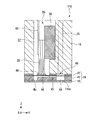
また、図7に示すようにポンプ室50aの容積を減少させる方向に変位したダイヤフラム51に当接可能な突起部90をポンプ室形成部材55に設けるようにしても構わない。この構成によれば、ポンプ室形成部材55に設けられた突起部90がダイヤフラム51に当接することで、ダイヤフラム51とポンプ室形成部材55との間に突起部90が介在するので、第1の磁性体81と第2の磁性体82とが接近し過ぎるのを防止することができ、第1の磁性体81及び第2の磁性体82間に生じる磁力の大きさを調整することができる。   Further, as shown in FIG. 7, the pump chamber forming member 55 may be provided with a protrusion 90 capable of contacting the diaphragm 51 displaced in the direction of decreasing the volume of the pump chamber 50 a. According to this configuration, since the protrusion 90 provided on the pump chamber forming member 55 contacts the diaphragm 51, the protrusion 90 is interposed between the diaphragm 51 and the pump chamber forming member 55. It is possible to prevent the magnetic body 81 and the second magnetic body 82 from being too close to each other, and the magnitude of the magnetic force generated between the first magnetic body 81 and the second magnetic body 82 can be adjusted.

1…プリンター(液体噴射装置)、6…インクカートリッジ(液体供給源)、34…減圧室形成部材、50a…ポンプ室、51…ダイヤフラム(変位部材)、55…ポンプ室形成部材、70…容積減少手段、71…減圧室、73…容積増大手段、75…ホール素子(変位検出部)、81…第1の磁性体、82…第2の磁性体、90…突起部、103…インク供給機構(液体供給装置)、106…制御装置(制御部)、110…ヘッド(液体噴射ヘッド) DESCRIPTION OF SYMBOLS 1 ... Printer (liquid ejecting apparatus), 6 ... Ink cartridge (liquid supply source), 34 ... Decompression chamber forming member, 50a ... Pump chamber, 51 ... Diaphragm (displacement member), 55 ... Pump chamber forming member, 70 ... Volume reduction Means 71: Decompression chamber 73 ... Volume increasing means 75 ... Hall element (displacement detection part) 81 ... First magnetic body 82 ... Second magnetic body 90 ... Projection part 103 ... Ink supply mechanism ( (Liquid supply device), 106... Control device (control unit), 110... Head (liquid ejection head)

Claims (7)

液体供給源側となる上流側から液体が消費される下流側に向けて前記液体を供給する液体供給流路と、
該液体供給流路の一部をポンプ室として該ポンプ室の容積を増減させるように該ポンプ室の内面の少なくとも一部を構成する変位部材が変位することによりポンプ駆動するポンプと、
前記ポンプ室の容積が増大する方向に前記変位部材を変位させる容積増大手段と、
前記ポンプ室の容積が減少する方向に前記変位部材を変位させる容積減少手段と、
を備え、
前記容積減少手段が、前記変位部材の前記ポンプ室の外側に設けられ、該ポンプ室の容積を減少させる方向に該変位部材を付勢するバネ部材と、前記変位部材に設けられた第1の磁性体と、前記ポンプ室を形成するポンプ室形成部材の前記第1の磁性体と対向する位置に配置されて該第1の磁性体との間で引き合う磁力を発生させる第2の磁性体と、を備える液体供給装置。
A liquid supply flow path for supplying the liquid from the upstream side which is the liquid supply source side toward the downstream side where the liquid is consumed;
A pump that drives the pump by displacing a displacement member that constitutes at least a part of the inner surface of the pump chamber so as to increase or decrease the volume of the pump chamber using a part of the liquid supply flow path as a pump chamber;
Volume increasing means for displacing the displacement member in a direction in which the volume of the pump chamber increases;
Volume reducing means for displacing the displacement member in a direction in which the volume of the pump chamber decreases;
With
The volume reduction means is provided outside the pump chamber of the displacement member, a spring member that biases the displacement member in a direction to reduce the volume of the pump chamber, and a first member provided in the displacement member A magnetic body and a second magnetic body that is disposed at a position facing the first magnetic body of the pump chamber forming member that forms the pump chamber, and generates a magnetic force attracting the first magnetic body; A liquid supply apparatus comprising:
前記変位部材が非磁性体で形成され、前記第1の磁性体が前記変位部材の前記ポンプ室の外側に配置されている請求項1に記載の液体供給装置。   The liquid supply device according to claim 1, wherein the displacement member is formed of a non-magnetic material, and the first magnetic material is disposed outside the pump chamber of the displacement member. 前記ポンプ室形成部材が非磁性体で形成され、前記第2の磁性体が前記ポンプ室形成部材の前記ポンプ室の外側に配置されている請求項1又は2に記載の液体供給装置。   3. The liquid supply apparatus according to claim 1, wherein the pump chamber forming member is formed of a nonmagnetic material, and the second magnetic material is disposed outside the pump chamber of the pump chamber forming member. 前記容積増大手段が、前記変位部材により前記ポンプ室と仕切られた減圧可能な減圧室と、該減圧室内の気体を吸引することで減圧する減圧手段と、を含む請求項1〜3のいずれか一項に記載の液体供給装置。   The volume increasing means includes a decompression-reducing decompression chamber partitioned from the pump chamber by the displacement member, and decompression means for decompressing by sucking a gas in the decompression chamber. The liquid supply apparatus according to one item. 前記第1の磁性体の変位を磁電変換素子により検出することにより前記変位部材の変位を検出する変位検出部と、該変位検出部の検出結果に基づいて前記減圧手段の駆動を制御する制御部と、を備える請求項4に記載の液体供給装置。   A displacement detector that detects the displacement of the displacement member by detecting the displacement of the first magnetic body with a magnetoelectric transducer, and a controller that controls the driving of the decompression means based on the detection result of the displacement detector And a liquid supply apparatus according to claim 4. 前記ポンプ室形成部材は、前記ポンプ室の容積を減少させる方向に変位した前記変位部材に当接可能な突起部が前記ポンプ室側に形成されている請求項1〜5のいずれか一項に記載の液体供給装置。   6. The pump chamber forming member according to any one of claims 1 to 5, wherein a protrusion that can contact the displacement member displaced in a direction to reduce the volume of the pump chamber is formed on the pump chamber side. The liquid supply apparatus as described. 液体を噴射する液体噴射ヘッドと、該液体噴射ヘッドに前記液体を供給する請求項1〜6のいずれか一項に記載の液体供給装置とを備える液体噴射装置。   A liquid ejecting apparatus comprising: a liquid ejecting head that ejects liquid; and the liquid supply apparatus according to claim 1 that supplies the liquid to the liquid ejecting head.
JP2011030958A 2011-02-16 2011-02-16 Liquid supply device and liquid injection device Withdrawn JP2012166509A (en)

Priority Applications (1)

Application Number Priority Date Filing Date Title
JP2011030958A JP2012166509A (en) 2011-02-16 2011-02-16 Liquid supply device and liquid injection device

Applications Claiming Priority (1)

Application Number Priority Date Filing Date Title
JP2011030958A JP2012166509A (en) 2011-02-16 2011-02-16 Liquid supply device and liquid injection device

Publications (1)

Publication Number Publication Date
JP2012166509A true JP2012166509A (en) 2012-09-06

Family

ID=46971135

Family Applications (1)

Application Number Title Priority Date Filing Date
JP2011030958A Withdrawn JP2012166509A (en) 2011-02-16 2011-02-16 Liquid supply device and liquid injection device

Country Status (1)

Country Link
JP (1) JP2012166509A (en)

Cited By (4)

* Cited by examiner, † Cited by third party
Publication number Priority date Publication date Assignee Title
JP2016538154A (en) * 2013-10-22 2016-12-08 ヒューレット−パッカード インダストリアル プリンティング リミテッド Control of ink flow to the printhead
US10059117B2 (en) 2016-08-12 2018-08-28 Seiko Epson Corporation Liquid ejecting apparatus and liquid supply method of liquid ejecting apparatus
US10421286B2 (en) 2017-02-24 2019-09-24 Seiko Epson Corporation Liquid ejecting apparatus and liquid supply method for liquid ejecting apparatus
US10525720B2 (en) 2017-06-02 2020-01-07 Seiko Epson Corporation Liquid ejecting apparatus and maintenance method for liquid ejecting apparatus

Cited By (5)

* Cited by examiner, † Cited by third party
Publication number Priority date Publication date Assignee Title
JP2016538154A (en) * 2013-10-22 2016-12-08 ヒューレット−パッカード インダストリアル プリンティング リミテッド Control of ink flow to the printhead
US10022976B2 (en) 2013-10-22 2018-07-17 Hewlett-Packard Development Company, L.P. Controlling an ink flow to a print head
US10059117B2 (en) 2016-08-12 2018-08-28 Seiko Epson Corporation Liquid ejecting apparatus and liquid supply method of liquid ejecting apparatus
US10421286B2 (en) 2017-02-24 2019-09-24 Seiko Epson Corporation Liquid ejecting apparatus and liquid supply method for liquid ejecting apparatus
US10525720B2 (en) 2017-06-02 2020-01-07 Seiko Epson Corporation Liquid ejecting apparatus and maintenance method for liquid ejecting apparatus

Similar Documents

Publication Publication Date Title
US7278718B2 (en) Liquid injecting apparatus
JP5655519B2 (en) Liquid supply valve unit and liquid ejecting apparatus
JP2017140760A (en) Liquid jetting head, liquid jetting device and method for controlling liquid jetting device
JP2012166509A (en) Liquid supply device and liquid injection device
JP4600328B2 (en) Liquid ejector
WO2005100031A1 (en) Liquid ejector cleaning method and liquid ejector
US10773526B2 (en) Liquid ejecting apparatus and maintenance method of liquid ejecting apparatus
JP2007152821A (en) Liquid container
JP6492816B2 (en) Valve device and control method thereof, and liquid jet device and control method thereof
JP2009160931A (en) Liquid ejecting device, printing apparatus and liquid supplying method
JP4415733B2 (en) Liquid ejecting apparatus and driving method thereof
JP2012210769A (en) Liquid ejection head and liquid ejection apparatus
JP4296954B2 (en) Circulation pump for liquid discharge device
JP4645750B2 (en) Liquid ejecting apparatus and driving method thereof
JP4935449B2 (en) Valve unit and fluid ejection device
JP4962486B2 (en) Suction cap device
JP2012192668A (en) Liquid injection head and liquid injection device
JP5791250B2 (en) Recording device
JP2012192661A (en) Valve mechanism and liquid ejecting apparatus
JP2009226881A (en) Fluid ejection device
JP2007261033A (en) Liquid ejector, and method for regulating pressure of liquid ejector
US20130187978A1 (en) Liquid ejection apparatus
JP2016147468A (en) Liquid jet device
JP2016155312A (en) Liquid discharge device and method of controlling the same
JP2011206956A (en) Liquid injection device and abnormality determination method of liquid detection part of the liquid injection device

Legal Events

Date Code Title Description
A300 Withdrawal of application because of no request for examination

Free format text: JAPANESE INTERMEDIATE CODE: A300

Effective date: 20140513