JP2012166346A - Image processor, image recorder and image processing method - Google Patents
Image processor, image recorder and image processing method Download PDFInfo
- Publication number
- JP2012166346A JP2012166346A JP2011026425A JP2011026425A JP2012166346A JP 2012166346 A JP2012166346 A JP 2012166346A JP 2011026425 A JP2011026425 A JP 2011026425A JP 2011026425 A JP2011026425 A JP 2011026425A JP 2012166346 A JP2012166346 A JP 2012166346A
- Authority
- JP
- Japan
- Prior art keywords
- image
- evaluation function
- recording
- drawing performance
- performance evaluation
- Prior art date
- Legal status (The legal status is an assumption and is not a legal conclusion. Google has not performed a legal analysis and makes no representation as to the accuracy of the status listed.)
- Withdrawn
Links
Images


Landscapes
- Ink Jet (AREA)
Abstract
Description
本発明は画像処理装置及び画像記録装置並びに画像処理方法に係り、特に記録画像の描画性能を補正する画像処理技術に関する。 The present invention relates to an image processing apparatus, an image recording apparatus, and an image processing method, and more particularly to an image processing technique for correcting a drawing performance of a recorded image.
汎用の画像記録装置として、インクジェット記録装置が知られている。インクジェット記録装置は、インクジェットヘッドに設けられた多数のノズルからインク液滴を吐出させて、記録媒体上の所望のカラー画像を記録する。 An ink jet recording apparatus is known as a general-purpose image recording apparatus. An ink jet recording apparatus records a desired color image on a recording medium by ejecting ink droplets from a number of nozzles provided in an ink jet head.
インクジェット方式の画像記録では、インクの増粘や異物の付着によりノズル詰まりが発生すると吐出異常の原因になる。吐出異常が発生すると、本来ドットが形成されるべき位置に描画がされず、画像品質を著しく低下させてしまう。 In the ink jet type image recording, if nozzle clogging occurs due to thickening of ink or adhesion of foreign matter, it causes ejection failure. When the ejection abnormality occurs, drawing is not performed at a position where a dot should be originally formed, and the image quality is significantly deteriorated.
特に、記録媒体の全幅に対応する長さにわたってノズルが設けられたフルライン型のインクジェットヘッドを用いて、記録媒体とインクジェットヘッドとを相対的に一回だけ操作させて、記録媒体の全域に対して画像記録を行うシングルパス方式の画像記録では、吐出異常ノズルに対応する画像上の位置にすじ状のむらが発生してしまう。 In particular, using a full-line type ink jet head provided with nozzles over a length corresponding to the entire width of the recording medium, the recording medium and the ink jet head are operated only once relative to the entire area of the recording medium. In single-pass image recording in which image recording is performed, streaky irregularities occur at positions on the image corresponding to ejection abnormal nozzles.
特許文献1は、複数の画素から構成される画像データに基づいて、同じノズルに割り当てられる画素群ごとに液体を噴射すべき画素数を算出し、噴射不良が発生する不良ノズルを検出して、不良ノズルが担う画素数が最小になるように画像の媒体上の位置が調整される液体噴射方法を開示している。
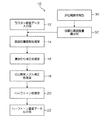
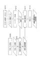
図13は、特許文献1に記載された液体噴射方法に適用される画像処理を簡略化して図示したフローチャートである。同図に示すフローチャートは、画像の媒体上の記録位置を調整する工程(ステップS200,ステップS202)と、画像を出力する工程(ステップS210〜ステップS216)に大別される。
FIG. 13 is a flowchart illustrating the image processing applied to the liquid ejecting method described in
画像の媒体上の記録位置を調整する工程では、インクジェットヘッドの不良ノズル検出が実行され、不良ノズル情報が取得される(ステップS200)。この不良ノズル情報は描画位置調整量算出(ステップS202)に用いられる。 In the step of adjusting the recording position of the image on the medium, defective nozzle detection of the inkjet head is executed, and defective nozzle information is acquired (step S200). This defective nozzle information is used for calculating the drawing position adjustment amount (step S202).
画像を出力する工程では、ラスター画像データが入力され(ステップS210)、入力されたラスター画像データに対してハーフトーン処理が施される(ステップS212)。ここで、「ラスター画像データ」とは、RGBの色空間で表される多階調値(例えば、0〜255)を有するデジタル画像データであり、ハーフトーン処理とは、多階調の画像データを二値又は多値(元の階調値よりも小さい階調値)のデータに変換する処理である。 In the step of outputting an image, raster image data is input (step S210), and halftone processing is performed on the input raster image data (step S212). Here, “raster image data” is digital image data having multi-gradation values (for example, 0 to 255) represented in an RGB color space, and halftone processing is multi-gradation image data. Is converted into binary or multi-valued data (gradation value smaller than the original gradation value).
ハーフトーン処理工程において得られたハーフトーン画像データと、予め求められている不良ノズル情報に基づいて、不良ノズルが担う画素数が最小になるように、画像の媒体上の位置(描画位置)の調整量が算出され(ステップS202)、該描画位置調整量に基づいて描画位置が調整される(ステップS214)。 Based on the halftone image data obtained in the halftone processing step and the defective nozzle information obtained in advance, the position of the image on the medium (drawing position) so that the number of pixels that the defective nozzle takes is minimized. An adjustment amount is calculated (step S202), and the drawing position is adjusted based on the drawing position adjustment amount (step S214).
このようにして描画位置が調整されたドットデータに基づいて画像出力(描画)が実行され(ステップS216)、不良ノズルの影響が抑制された描画位置調整済みの描画画像が記録される。 Image output (drawing) is executed based on the dot data whose drawing position has been adjusted in this way (step S216), and a drawing image whose drawing position has been adjusted with the influence of defective nozzles suppressed is recorded.
なお、特許文献1に開示された補正方法の他にも、吐出異常ノズルによる打滴を補正する方法は多数提案されている。例えば、吐出異常ノズルの近傍の正常ノズルを吐出異常ノズルの補正ノズルとし、該補正ノズルによる描画濃度を上げることで吐出異常ノズルに起因するすじ状のむらの視認性を下げる方法が挙げられる。
In addition to the correction method disclosed in
描画濃度を上げるには、ドット径を大きくする、画像データ上の濃度階調値を上げる、などが考えられる。なお、上記の吐出異常ノズルの補正方法は、補正性能の階調依存性によって吐出異常ノズルに起因する濃度むらを補正しきれないことがありうるので、この点について考慮する必要がある。 To increase the drawing density, it is conceivable to increase the dot diameter or increase the density gradation value on the image data. Note that the above-mentioned correction method for abnormal discharge nozzles may not be able to correct uneven density due to abnormal discharge nozzles due to the gradation dependence of the correction performance, so this point needs to be considered.
吐出異常ノズルに起因する画像品質の低下は、画像上のすじ状のむらとして視認される。画像品質の低下と認識される他のむらとして、インクジェットヘッドを構成するヘッドモジュールの固体差によるもの、インクの吐出むら(ノズルごとの吐出特性の違い)により発生する濃度むら、描画プロセス中における装置の振動に起因して発生する振動むら、などが挙げられる。 The deterioration of the image quality caused by the abnormal ejection nozzle is visually recognized as a stripe-like unevenness on the image. Other non-uniformities recognized as degradation in image quality are due to differences in the solidity of the head modules that make up the inkjet head, non-uniformity in the density of ink that occurs due to non-uniformity in ink ejection (difference in ejection characteristics for each nozzle), Examples include vibration unevenness caused by vibration.
特許文献1に記載された液体噴射方法は、不良ノズルに起因する濃度むらのみに着目して画像位置の調整をしているが、上記に挙げたような他のむらの発生について考慮されていない。
The liquid ejecting method described in
また、特許文献1に記載された液体噴射方法は、不良ノズルに割り当てられた画素群の画素数の積算値を評価対象としている。不良ノズルに割り当てられた画素群の画素数を算出するには、ラスターイメージ形式などの元画像データ(各画素の濃度値を多階調で表したデータ)に対してハーフトーン処理(量子化処理)などの処理を施して、ドットの位置情報を取得する必要がある。
In addition, the liquid ejection method described in
しかし、ドットの位置情報に基づいて不良ノズルの補正処理を行うと、各画素の濃度情報を用いることができず、不良ノズルに起因する濃度むら以外のむらの影響を考慮することができない。 However, when the defective nozzle correction process is performed based on the dot position information, the density information of each pixel cannot be used, and the influence of unevenness other than the uneven density due to the defective nozzle cannot be considered.
本発明はこのような事情に鑑みてなされたもので、吐出異常(不良)ノズルに起因する濃度むらや他の要因に起因するむらの影響が抑制された好ましい画像記録が実現される画像処理装置及び画像記録装置並びに画像処理方法を提供することを目的とする。 The present invention has been made in view of such circumstances, and an image processing apparatus that realizes preferable image recording in which the influence of uneven density due to abnormal discharge (defective) nozzles and unevenness due to other factors is suppressed. It is another object of the present invention to provide an image recording apparatus and an image processing method.
上記目的を達成するために、本発明に係る画像処理装置は、記録ヘッドに具備された記録素子を動作させて記録される画像の描画性能を定量的に表す評価値を求めるための描画性能評価関数を、少なくとも一つ取得する描画性能評価関数取得手段と、複数の画素から構成される多階調の画像を表すラスター画像データを取得するラスター画像データ取得部と、前記取得されたラスター画像データに対して、前記記憶されている描画性能評価関数により求められた評価値が最良の描画性能を示すように、記録画像の記録媒体上における位置を算出する描画位置算出手段と、前記算出された記録媒体上の位置に画像が記録されるように、前記ラスター画像データを調整する描画位置調整手段と、を備えたことを特徴とする。 In order to achieve the above object, an image processing apparatus according to the present invention provides a drawing performance evaluation for obtaining an evaluation value that quantitatively represents a drawing performance of an image recorded by operating a recording element provided in a recording head. A drawing performance evaluation function acquisition unit that acquires at least one function, a raster image data acquisition unit that acquires raster image data representing a multi-tone image composed of a plurality of pixels, and the acquired raster image data On the other hand, the drawing position calculating means for calculating the position of the recorded image on the recording medium so that the evaluation value obtained by the stored drawing performance evaluation function shows the best drawing performance, and the calculated And a drawing position adjusting means for adjusting the raster image data so that an image is recorded at a position on the recording medium.
本発明によれば、ラスター画像データに対して、描画性能を定量的に表す評価値を算出するための描画性能関数が適用されて該評価値が求められ、当該評価値が最良の描画性能を示すように記録媒体上の記録画像の位置が算出され、当該算出された位置に記録画像が記録されるようにラスター画像データが調整されるので、各種のむらが抑制された好ましい画像記録を行うことが可能である。 According to the present invention, a rendering performance function for calculating an evaluation value that quantitatively represents rendering performance is applied to raster image data to obtain the evaluation value, and the evaluation value has the best rendering performance. As shown, the position of the recorded image on the recording medium is calculated, and the raster image data is adjusted so that the recorded image is recorded at the calculated position, so that preferable image recording in which various irregularities are suppressed is performed. Is possible.
以下、添付図面に従って本発明の好ましい実施の形態について詳説する。 Hereinafter, preferred embodiments of the present invention will be described in detail with reference to the accompanying drawings.
〔画像処理装置(方法)の説明〕
図1は、本発明の実施形態に係る画像処理装置の概略構成を示すブロック図である。同図に示す画像処理装置10は、インクジェット方式による画像記録において、ラスター画像データ(多階調のデジタル画像データ)を二値又は多値のハーフトーン画像データ(ドット情報を表すデータ)に変換するものであり、描画性能評価関数に基づいて、ラスター画像データに対して記録媒体上における画像位置の調整処理が行われ、ハーフトーン画像データが出力されるように構成されている。
[Description of Image Processing Apparatus (Method)]
FIG. 1 is a block diagram showing a schematic configuration of an image processing apparatus according to an embodiment of the present invention. The image processing apparatus 10 shown in FIG. 1 converts raster image data (multi-tone digital image data) into binary or multi-value halftone image data (data representing dot information) in image recording by an inkjet method. According to the drawing performance evaluation function, the raster image data is subjected to image position adjustment processing on the recording medium, and halftone image data is output.
すなわち、画像処理装置10は、ラスター画像データ(例えば、RGB色空間で表現される0から255の階調値で表されるデジタル形式のシリアルデータ)が入力されるラスター画像データ入力部12と、描画性能評価関数を用いて求められた描画位置調整量に基づいて、ラスター画像データに対して描画位置調整処理が施される描画位置調整処理部14と、描画位置が調整されたラスター画像データに対して、記録ヘッドの固体差に起因する濃度むら補正処理が施される濃度むら補正処理部16と、吐出異常ノズル(異常記録素子)の補正処理が施される吐出異常ノズル補正処理部18と、補正処理後のラスター画像データに対してハーフトーン処理が施されるハーフトーン処理部20と、ハーフトーン処理後のハーフトーン画像データが出力されるハーフトーン画像データ出力部22と、を備えて構成されている。
That is, the image processing apparatus 10 includes a raster image
また、画像処理装置10は、描画性能評価関数、又は描画性能評価関数を構成する要因別の描画性能評価関数(むら評価関数)が取得される評価関数取得部30と、取得された描画性能評価関数又は要因別の描画性能評価関数に基づいて算出された描画性能評価関数の評価値が算出され、該評価値が最良の描画性能を示すように記録画像の描画位置の調整量が算出される描画位置調整量算出部32と、を具備している。なお、取得されたむら評価関数が記憶されるむら評価関数記憶部を備える形態も可能である。
The image processing apparatus 10 also includes an evaluation
詳細は後述するが、「描画性能評価関数」は、記録媒体上に記録された記録画像に発生する描画性能(描画むら)を定量的に評価するための評価値の導出に適用され、複数の種類の描画むらの影響や、当該描画むらの補正性能の画像階調への依存性を考慮するために、ラスターイメージ分布(ラスター画像データ)Iを処理して導出される。 As will be described in detail later, the “drawing performance evaluation function” is applied to derivation of an evaluation value for quantitatively evaluating the drawing performance (drawing unevenness) generated in the recorded image recorded on the recording medium. In order to consider the influence of the type of unevenness of drawing and the dependency of the correction performance of the unevenness of drawing on the image gradation, the raster image distribution (raster image data) I is processed and derived.
すなわち、描画性能評価関数により求められた評価値の大小を比較することで、描画性能の良し悪しを把握することができる。 That is, it is possible to grasp whether the drawing performance is good or bad by comparing the evaluation values obtained by the drawing performance evaluation function.
描画性能評価関数F(X,Y)は、次式(1)により表される。 The drawing performance evaluation function F (X, Y) is expressed by the following equation (1).
![]()
![]()
ここで、(X,Y)は、直交座標系により表される記録画像上の位置であり、(x,y)は直交座標系により表される画像内の座標である。例えば、X(x)を記録媒体と記録ヘッドの相対搬送方向と直交するノズル配列方向とし、Y(y)を記録媒体と記録ヘッドの相対搬送方向とする形態がある。 Here, (X, Y) is a position on the recorded image represented by the orthogonal coordinate system, and (x, y) is a coordinate in the image represented by the orthogonal coordinate system. For example, there is a form in which X (x) is the nozzle arrangement direction orthogonal to the relative conveyance direction of the recording medium and the recording head, and Y (y) is the relative conveyance direction of the recording medium and the recording head.
要因別の描画性能評価関数(以下、むら評価関数と記載することがある。)Mn(X,Y,I)は、記録画像の位置を(X,Y)に移動させたときの描画むらの発生度合いと補正性能を評価する関数である。nはむらの種類(属性、発生要因)を表す添字である。むら評価関数Mnの添字nは、1から順に付けられた正の整数により表されることや、むらの種類を示す記号、文字、文字列により表されることがある。 Drawing performance evaluation function for each factor (hereinafter sometimes referred to as unevenness evaluation function) M n (X, Y, I) is unevenness of drawing when the position of the recorded image is moved to (X, Y). This is a function for evaluating the degree of occurrence and correction performance. n is a subscript representing the type of unevenness (attribute, generation factor). The subscript n of the unevenness evaluation function Mn may be represented by a positive integer attached in order from 1, or may be represented by a symbol, character, or character string indicating the type of unevenness.
上記式(1)に示すように、描画性能評価関数F(X,Y)は、描画むらの種類が一種類の場合は当該むらに対応するむら評価関数Mと一致し、描画むらの種類が複数の場合は描画むらの種類ごとのむら評価関数Mn(X,Y,I)が合成された合成関数として表される。 As shown in the above equation (1), the drawing performance evaluation function F (X, Y) matches the unevenness evaluation function M corresponding to the unevenness when the kind of unevenness in drawing is one, and the type of unevenness in drawing is as follows. In the case of multiple, the unevenness evaluation function M n (X, Y, I) for each type of drawing unevenness is expressed as a combined function.
上記式(1)に図示された描画性能評価関数F(X,Y)から求められる評価値が最小化されることで、記録媒体上の記録画像の位置(X,Y)が最適化される。すなわち、描画位置調整量算出部32は、描画性能評価関数F(X,Y)に基づき算出される評価値が最小となる記録媒体上の記録画像の位置(X,Y)が算出され、該記録画像の位置(X,Y)に基づいてラスター画像データ上の記録画像の位置が調整される。
The position (X, Y) of the recorded image on the recording medium is optimized by minimizing the evaluation value obtained from the drawing performance evaluation function F (X, Y) shown in the above equation (1). . That is, the drawing position adjustment
ラスター画像データにおける記録画像の位置を調整する形態には、記録画像の書き出し位置を変更する形態でもよいし、ラスター画像データ内の記録画像に対応するデータの分布を変更する形態でもよい。 The form for adjusting the position of the recording image in the raster image data may be a form for changing the writing position of the recording image, or a form for changing the distribution of data corresponding to the recording image in the raster image data.
また、画像を微小角度回転させる形態がありうる。例えば、直線を描画するときに、記録媒体の搬送方向と吐出異常によるすじ状の濃度むら(白すじ)の方向が完全に平行であるとすると、当該すじ状の濃度むらが目立ってしまうが、記録媒体の搬送方向に対して直線を微小角度だけ回転させてずらすと、その影響が下がり、すじ状の濃度むらの視認性を低減化させることが可能である。 There may be a form in which the image is rotated by a minute angle. For example, when a straight line is drawn, if the conveyance direction of the recording medium and the direction of stripe-like density unevenness (white stripes) due to ejection abnormality are completely parallel, the stripe-like density unevenness becomes conspicuous. When the straight line is rotated by a minute angle and shifted with respect to the recording medium conveyance direction, the influence is reduced, and the visibility of streaky density unevenness can be reduced.
描画性能評価関数F(X,Y)は、装置ごと(記録ヘッドごと)に描画むらの種類に対応して、描画むらの種類ごとに導出され、装置(記録ヘッド)及び描画むらの種類に対応付けされる。 The drawing performance evaluation function F (X, Y) is derived for each type of drawing unevenness corresponding to the type of drawing unevenness for each device (for each recording head), and corresponds to the type of device (recording head) and drawing unevenness. Attached.
図2は、図1に示す画像処理装置10に適用される画像処理方法の流れを示すフローチャートである。 FIG. 2 is a flowchart showing a flow of an image processing method applied to the image processing apparatus 10 shown in FIG.
ラスター画像データが入力されると(ステップS12)、入力されたラスター画像データ40に対して、色変換処理(RGB→CMY)、ガンマ補正処理が施された後に、図1の描画位置調整処理部14において、描画むらの発生が最大限に抑制され、描画性能が最適化されるように記録媒体上の記録画像の位置が調整される(図2のステップS14)。
When the raster image data is input (step S12), the input
次に、図1の濃度むら補正処理部16において、描画位置が調整されたラスター画像データに対して、ノズル(記録素子)ごとの記録特性(記録ヘッドの固体差)に起因する濃度むらの補正処理が施される(図2のステップS16)。
Next, the density unevenness
さらに、図1の吐出異常ノズル補正処理部18において、描画位置が調整されたラスター画像データに対して、吐出異常ノズルに起因する描画むら(すじ状のむら)の補正処理が施される(図2のステップS18)。
Further, the ejection abnormal nozzle
ここでいう「吐出異常ノズル」とは、液滴の吐出を行うことができない不吐出ノズルと、液滴の吐出を行うことができるものの、吐出量の異常や吐出方向の異常が発生するノズルと、を含む概念である。 The term “discharge abnormal nozzle” as used herein refers to a non-discharge nozzle that cannot discharge liquid droplets, and a nozzle that can discharge liquid droplets but generates abnormal discharge amounts or abnormal discharge directions. This is a concept that includes
上述したように、描画位置調整工程(ステップS14)、濃度むら補正処理工程(ステップS16)、及び吐出異常ノズル補正処理工程(ステップS18)を経たラスター画像データは、図1のハーフトーン処理部20において、ハーフトーン処理が施され(ステップS20)、ハーフトーン画像データ42が生成される。
As described above, the raster image data that has undergone the drawing position adjustment step (step S14), the density unevenness correction processing step (step S16), and the ejection abnormal nozzle correction processing step (step S18) is the
このハーフトーン画像データ42は、二値又は多値のドット情報が含まれている。例えば、1画素を1ドットで表すと二階調を表現することができで、1画素を4ドットで表すと四階調を表現できる。このハーフトーン画像データが表すドット情報に基づいてインクジェットヘッドを動作させるための駆動信号(駆動電圧)が生成される(詳細後述)。 The halftone image data 42 includes binary or multivalued dot information. For example, if one pixel is expressed by one dot, two gradations can be expressed, and if one pixel is expressed by four dots, four gradations can be expressed. A drive signal (drive voltage) for operating the inkjet head is generated based on dot information represented by the halftone image data (details will be described later).
このようにして生成された駆動信号を用いてインクジェットヘッドを動作させて、描画位置調整済みの記録(描画)画像44が出力される(ステップS22)。 The inkjet head is operated using the drive signal generated in this way, and the recording (drawing) image 44 with the drawing position adjusted is output (step S22).
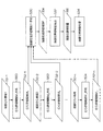
図3は、図2に示した描画位置調整工程(ステップS14)の詳細を示すフローチャートである。同図に示すように、n個(nは正の整数)の描画むら情報1、2、…、n(符号50‐1、50‐2、…、50‐nを付して図示)に基づいて、n個の描画むら評価関数M(M1〜Mn、符号52‐1〜52‐nを付して図示)が生成されており(ステップS50〜ステップS54)、このn個のむら評価関数M1〜Mnの中から少なくとも1つのむら評価関数Mが選択的に取得される。
FIG. 3 is a flowchart showing details of the drawing position adjusting step (step S14) shown in FIG. As shown in the figure, based on n pieces (n is a positive integer) drawing
2つ以上のむら評価関数Mが取得された場合は、取得された複数のむら評価関数Mの合成関数である描画性能評価関数Fが生成される(ステップS30)。符号54を付して図示した描画性能評価関数Fにより算出される評価値が最小となるように、描画位置調整量56(x−X,y−y)が算出され(ステップS32)、該描画位置調整量56に基づいて、ラスター画像データ上の描画位置の調整処理が施される(ステップS34)。
When two or more unevenness evaluation functions M are acquired, a drawing performance evaluation function F that is a composite function of the acquired multiple unevenness evaluation functions M is generated (step S30). The drawing position adjustment amount 56 (x−X, y−y) is calculated so that the evaluation value calculated by the drawing performance evaluation function F illustrated with
なお、描画むら情報50−1〜50−nに基づくむら評価関数M1〜Mn(52−1〜52−n)の作成工程を、当該画像処理装置において実行する形態や、複数のむら評価関数Mに基づいて予め作成された描画性能評価関数F(54)を取得する形態も可能である。
Note that the creation process of drawing unevenness information 50-1 to 50-n
〔むら評価関数Mの具体例〕
次に、むら評価関数Mの具体例について説明する。以下の説明では、むら評価関数のパラメータとして直交座標系(x,y)が用いられる。本例では、x方向は記録媒体と記録ヘッドとの相対移動方向と直交するノズルの実質的な配列方向とし、y方向は記録媒体と記録ヘッドとの相対移動方向とする。
[Specific example of unevenness evaluation function M]
Next, a specific example of the unevenness evaluation function M will be described. In the following description, an orthogonal coordinate system (x, y) is used as a parameter of the unevenness evaluation function. In this example, the x direction is a substantial arrangement direction of nozzles orthogonal to the relative movement direction between the recording medium and the recording head, and the y direction is the relative movement direction between the recording medium and the recording head.
フルライン型記録ヘッドを具備する形態では、x方向は実質的なノズル配列方向(記録媒体の幅方向)であり、y方向は記録媒体と記録ヘッドとの相対移動方向(記録媒体の搬送方向)である。一方、シリアル型記録ヘッドを具備する形態では、x方向はノズルの配列方向であり、y方向は記録ヘッドの走査方向(記録媒体の幅方向)である。 In an embodiment having a full-line type recording head, the x direction is a substantial nozzle arrangement direction (the width direction of the recording medium), and the y direction is the relative movement direction of the recording medium and the recording head (the conveyance direction of the recording medium). It is. On the other hand, in the embodiment having a serial type recording head, the x direction is the nozzle arrangement direction, and the y direction is the scanning direction of the recording head (the width direction of the recording medium).
(記録ヘッドの固体差に起因する濃度むら評価関数Mdensityの説明)
図4(a),(b)は、記録ヘッドの固体差に起因する濃度むらの説明図である。図4(a)は記録ヘッド60の固体差に起因する濃度むらが発生している状態が模式的に図示されている。
(Explanation of density unevenness evaluation function M density caused by individual difference of recording head)
FIGS. 4A and 4B are explanatory diagrams of density unevenness caused by individual differences in the recording head. FIG. 4A schematically shows a state in which density unevenness due to the solid difference of the
記録ヘッド60はフルライン型記録ヘッドであり、複数のノズル60がx方向に沿って一列に配置された構造を有している。複数のノズル62のうち、同図中左から三番目のノズル64、四番目のノズル65の吐出特性が他のノズル62と異なり、飛翔方向がずれてしまう傾向がある。
The
そうすると、ノズル64,65によって形成されるドットの位置にずれが生じ、記録媒体66上の座標(x,y)に形成される記録画像68に濃度むら70が発生する。なお、記録媒体66上の記録画像68の座標(x,y)は、同図中左上の角部の座標としている。
Then, the positions of the dots formed by the
記録ヘッドの固体差には、記録ヘッドを構成するヘッドモジュール(図6、7参照)の固体差、ヘッドモジュールの取り付けのばらつき、インクの吐出特性の違い(ノズルの機械加工のばらつき)などが挙げられる。 The individual difference of the recording head includes the individual difference of the head modules (see FIGS. 6 and 7) constituting the recording head, the variation in the mounting of the head module, the difference in the ink ejection characteristics (variation in the machining of the nozzle), and the like. It is done.
一般に、このような吐出特性が異なるノズル64は複数存在するので、かかる吐出特性に起因して周期的な濃度むらが生じる。該濃度むらの空間周波数が人間の目により視認される範囲であると記録画像の品質を著しく低下させてしまう。
In general, since there are a plurality of
図4(a)に図示された濃度むら70を補正するために、濃度むらを計測するためのテストチャートを出力し、当該濃度むらを計測するためのテストチャートを光学読取装置により読み取って濃度むら情報を計測し、計測された濃度むら情報に基づいて濃度むら補正処理が実行される。
In order to correct the
しかし、ヘッドモジュール間のつなぎ部(オーバーラップ部)の位置や、吐出異常ノズルが密集している位置などでは、濃度むら補正性能が低下してしまい、十分な補正性能が発揮されないことがありうる。 However, the density unevenness correction performance may deteriorate at the position of the connecting portion (overlap portion) between the head modules, the position where the abnormal discharge nozzles are dense, and the like, and sufficient correction performance may not be exhibited. .
そこで、濃度むら補正性能が低下する可能性が高い位置に対応するノズルの使用を極力避けるために、濃度むら補正性能を表す濃度むら評価関数Mdensity(X,Y,I)が用意される。 Therefore, in order to avoid the use of a nozzle corresponding to a position where the density unevenness correction performance is likely to be reduced, a density unevenness evaluation function M density (X, Y, I) representing the density unevenness correction performance is prepared.
濃度むら評価関数MDensity(X,Y,I)は、次式(2)により表される。 The density unevenness evaluation function M Density (X, Y, I) is expressed by the following equation (2).
![]()
![]()
上記式(2)におけるCDensity(x,y,liquid,I(x−X,y−Y,liquid))は、ある座標(x,y)、液種(liquid)、階調(I)における濃度むら補正性能を表す評価関数とする。評価関数CDensityは、ヘッドモジュールの設計情報(ノズルの飛翔曲がりの情報、ノズル径のばらつきの情報、ノズルのモジュール内(ヘッド内)位置情報(モジュール内の何番目のノズルであるかの情報、位相情報等))、や、吐出異常ノズルの発生情報(吐出異常ノズルの位置情報、吐出異常ノズル間の間隔情報、各ノズルからのインク吐出量(ドット径)の設計値からのずれ量等)などに基づいて、予めルックアップテーブルとして作成しておけばよい。 C Density (x, y, liquid, I (x-X, y-Y, liquid)) in the above formula (2) is a certain coordinate (x, y), liquid type (liquid), and gradation (I). The evaluation function represents density unevenness correction performance. The evaluation function C Density is the design information of the head module (nozzle flying curve information, nozzle diameter variation information, nozzle module (within the head) position information (information about the number of nozzles in the module, Phase information, etc.), occurrence information of abnormal discharge nozzles (position information of abnormal discharge nozzles, spacing information between abnormal discharge nozzles, deviation amount of ink discharge amount (dot diameter) from each nozzle, etc.) Based on the above, a lookup table may be created in advance.
上記式(2)を、式(1)に与えてF(X,Y)を最小化することにより、記録ヘッドの固体差に起因する濃度むら補正性能が考慮された記録媒体66上の記録画像68の最適位置(X,Y)が求められる。
The above-described expression (2) is given to expression (1) to minimize F (X, Y), so that the recorded image on the
図4(b)は、記録媒体66上の最適位置(X,Y)に記録画像68を移動させた状態が模式的に図示されている。記録ヘッド60の固体差に起因する濃度むら70の発生位置(一点破線により図示)が避けられて、記録画像68の最適位置(X,Y)が決められている。
FIG. 4B schematically shows a state in which the recorded
なお、当該記録画像の位置調整によっても、ノズル65の吐出特性に起因する濃度むらは解消されていないように思われるが、ノズル64の吐出特性に起因する濃度むらを抑制することでむらの視認性を低下させている。また、濃度むら補正の効果によって、当該濃度むらの視認性をさらに低下させることができる。
Although it seems that the density unevenness due to the ejection characteristics of the
(吐出異常ノズルに起因するむら評価関数Mnzlの説明)
次に、吐出異常ノズルに起因するむらを対象とした、むら評価関数Mnzlについて説明する。なお、以下の説明では、先に説明した構成と同一又は類似する構成は同一の符号を付し、その説明は省略する。
(Explanation of unevenness evaluation function M nzl caused by ejection abnormal nozzle)
Next, a non-uniformity evaluation function M nz1 for non-uniformity caused by abnormal ejection nozzles will be described. In the following description, the same or similar components as those described above are denoted by the same reference numerals, and the description thereof is omitted.
図5(a),(b)は、吐出異常ノズルに起因するむらの説明図である。図5(a)は吐出異常ノズル64’に起因するすじ状のむら72が発生している状態が模式的に図示されている。
FIGS. 5A and 5B are explanatory diagrams of unevenness caused by abnormal ejection nozzles. FIG. 5A schematically shows a state in which streak-
かかる吐出異常ノズルに起因するすじ状のむら72を補正するために、吐出異常ノズルの周辺に位置する正常ノズルに対応する画素の濃度値を上げるように、ラスター画像データ又はハーフトーン画像データのいずれかが補正される。
Either raster image data or halftone image data is used to increase the density value of pixels corresponding to normal nozzles located around the abnormal discharge nozzles in order to correct
しかし、吐出異常ノズルが密集する場合は、補正性能が低下してしまい、十分な補正性能が発揮されないことがありうる。 However, when the abnormal discharge nozzles are densely packed, the correction performance is deteriorated, and the sufficient correction performance may not be exhibited.
そこで、補正性能が低下する可能性が高い位置に対応するノズルの使用を極力避けるために、吐出異常ノズルの発生度合い及び吐出異常ノズルの補正性能を表すむら評価関数Mnzl(X,Y,I)が用意される。むら評価関数Mnzl(X,Y,I)は、次式(3)により表される。 Therefore, in order to avoid the use of the nozzle corresponding to the position where the correction performance is likely to be reduced as much as possible, the unevenness evaluation function M nzl (X, Y, I) representing the occurrence degree of the abnormal discharge nozzle and the correction performance of the abnormal discharge nozzle. ) Is prepared. The unevenness evaluation function M nzl (X, Y, I) is expressed by the following equation (3).
![]()
![]()
上記式(3)におけるN(x,color)は、吐出異常ノズルの情報等に基づいて各ノズルに与えられる重み付け値であり、座標(ノズル位置)(x)と色(ヘッド)(color)がパラメータとなる。 In the above equation (3), N (x, color) is a weighting value given to each nozzle based on the information of the ejection abnormal nozzle and the coordinates (nozzle position) (x) and color (head) (color) are It becomes a parameter.
また、Cnzl(x,liquid,I(x−X,y−Y,liquid))は、あるノズル位置(x)、液種(liquid)、階調(I)における吐出異常ノズル補正性能を表す評価関数である。 Further, C nzl (x, liquid, I (x−X, y−Y, liquid)) represents ejection abnormal nozzle correction performance at a certain nozzle position (x), liquid type (liquid), and gradation (I). An evaluation function.
この重み付け値N(x,color)及び評価関数Cnzl(x,liquid,I)は、吐出異常ノズル情報及び吐出異常ノズルの補正性能を予め計測しておき、ルックアップテーブルとして作成しておけばよい。 The weighting value N (x, color) and the evaluation function C nzl (x, liquid, I) should be prepared as a lookup table by measuring the ejection abnormal nozzle information and the correction performance of the ejection abnormal nozzle in advance. Good.
上記式(3)を、式(1)に与えてF(X,Y)を最小化することにより、吐出異常ノズルの補正性能が考慮された記録媒体上の記録画像の最適位置(X,Y)が求められる。 By giving the above equation (3) to equation (1) and minimizing F (X, Y), the optimum position (X, Y) of the print image on the print medium in consideration of the correction performance of the ejection abnormal nozzle is considered. ) Is required.
図5(b)は、記録媒体66上の最適位置(X,Y)に記録画像68を移動させた状態が模式的に図示されている。吐出異常ノズル64’に起因するすじ状のむら72の発生位置(一点破線により図示)が避けられて、記録画像68の最適位置(X,Y)が決められている。
FIG. 5B schematically shows a state in which the recorded
(振動むら評価関数Mvibeの説明)
画像記録プロセスや装置の設計により、画像記録中にそのプロセス(装置)に固有の振動(共振現象)が発生してしまうことがある。この振動は記録媒体の搬送方向(例えば、y方向)、記録媒体の搬送方向と直交する方向(例えば、x方向)のいずれにも発生する可能性がある。かかる振動の発生に起因して記録画像にむら(振動むら)が発生してしまうことがある。
(Explanation of the vibration unevenness evaluation function M vibe )
Depending on the design of the image recording process and the apparatus, vibration (resonance phenomenon) inherent to the process (apparatus) may occur during image recording. This vibration may occur both in the recording medium conveyance direction (for example, the y direction) and in a direction orthogonal to the recording medium conveyance direction (for example, the x direction). Due to the occurrence of such vibration, unevenness (vibration unevenness) may occur in the recorded image.
振動むらの多くは、画像記録プロセスの周期性や装置動作の周期性に起因して発生するので、記録媒体上における振動むらの発生位置は比較的安定している(再現性が高い)。また、記録媒体上に発生する振動むらによる影響は記録媒体の端部になるほど大きくなる傾向があるために、振動むらの発生位置は特定することが可能である。 Since most of the vibration unevenness occurs due to the periodicity of the image recording process and the periodicity of the apparatus operation, the occurrence position of the vibration unevenness on the recording medium is relatively stable (high reproducibility). In addition, since the influence of vibration unevenness generated on the recording medium tends to increase as the end of the recording medium is reached, the occurrence position of vibration unevenness can be specified.
図6(a)は、x方向に沿う振動むら76が発生した記録媒体66上の記録画像68が模式的に図示されている。該振動むら76のy座標をy1とする。
FIG. 6A schematically shows a recorded
かかる振動むらの発生度合いを表す振動むら評価関数Mvibeは、次式(4)により表される。 The vibration unevenness evaluation function M vibe representing the degree of occurrence of such vibration unevenness is expressed by the following equation (4).
![]()
![]()
上記式(4)におけるCvibe(x,y,liquid,I(x−X,y−Y,liquid))は、座標(x,y)、液種(liquid)、階調(I)をパラメータとする振動むらの発生度合いを表す評価関数である。 C vibe (x, y, liquid, I (x-X, y-Y, liquid)) in the above equation (4) is a parameter of coordinates (x, y), liquid type (liquid), and gradation (I). Is an evaluation function representing the degree of occurrence of vibration unevenness.
上記式(4)を、式(1)に与えてF(X,Y)を最小化することにより、振動むらの発生度合いが考慮された記録媒体上の記録画像の最適位置(X,Y)が求められる。 By giving the above equation (4) to equation (1) and minimizing F (X, Y), the optimum position (X, Y) of the recorded image on the recording medium in consideration of the degree of occurrence of vibration unevenness. Is required.
図6(b)は、記録媒体66上の最適位置(X,Y)に記録画像68を移動させた状態が模式的に図示されている。振動むら76の発生位置y1(一点破線により図示)が避けられて、記録画像68の最適位置(X,Y)が決められている。
FIG. 6B schematically shows a state in which the recorded
なお、上述したむら評価関数Mの具体例以外にも、記録媒体上の位置(x,y)を特定できるむらであれば、当該むらの発生度合いや補正性能を表す評価関数(Cdensity等)に基づきむら評価関数Mを作成し、当該むら補正関数Mを上記式(1)に与えて、F(X,Y)を最小化することにより、当該むらの発生度合い、当該むらの補正性能が考慮された記録媒体上の記録画像の最適位置(X,Y)を求めることが可能である。 In addition to the specific example of the unevenness evaluation function M described above, if the unevenness can identify the position (x, y) on the recording medium, an evaluation function (C density, etc.) representing the degree of occurrence of the unevenness and the correction performance. The unevenness evaluation function M is created based on the above, and the unevenness correction function M is given to the above equation (1) to minimize F (X, Y). It is possible to determine the optimum position (X, Y) of the recorded image on the considered recording medium.
上記の如く構成された画像処理装置及び画像処理方法によれば、予め生成された描画性能評価関数F(むら評価関数M)計算により、描画性能が最適化された描画位置調整量(X,Y)によりラスター画像データが調整されるので、ハーフトーン処理後のハーフトーン画像データ(ハーフトーンイメージ分布)に対して記録画像の位置が調整される画像処理と比較して、より画像劣化を抑制することが可能となる。 According to the image processing apparatus and the image processing method configured as described above, the drawing position adjustment amount (X, Y) in which the drawing performance is optimized by the calculation of the drawing performance evaluation function F (unevenness evaluation function M) generated in advance. ) Adjusts the raster image data, so that the image deterioration is further suppressed as compared with the image processing in which the position of the recorded image is adjusted with respect to the halftone image data (halftone image distribution) after the halftone processing. It becomes possible.
特に、ラスター画像データを対象とすることで、ハーフトーン画像データを対象とするときには考慮することができない吐出特性に起因する濃度むらについての考慮が可能となる。 In particular, by targeting raster image data, it is possible to consider density unevenness due to ejection characteristics that cannot be considered when halftone image data is targeted.
〔応用例〕
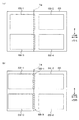
次に、描画性能評価関数F(X,Y)に基づく、ラスター画像データの調整処理の応用例について説明する。本応用例では、面付け(ページ割り当て)に応用した例について説明する。
[Application example]
Next, an application example of raster image data adjustment processing based on the drawing performance evaluation function F (X, Y) will be described. In this application example, an example applied to imposition (page allocation) will be described.
図7(a),(b)は、本応用例に係る記録画像の位置調整処理を模式的に図示した説明図である。 FIGS. 7A and 7B are explanatory views schematically showing a position adjustment process of a recorded image according to this application example.
図7(a)は、菊全判サイズ(939mm×639mm)の記録媒体66に、A4切サイズ(440mm×312mm)に対応する4つの記録画像68‐1,68‐2,68‐3,68‐4が形成された状態が図示されている。
FIG. 7A shows four recording images 68-1, 68-2, 68-3, 68- corresponding to an A4 cut size (440 mm × 312 mm) on a
同図に符号74を付して破線により図示した吐出異常ノズル(図5に符号64’を付して図示)に起因するすじ状のむら74が発生している。このすじ状のむら74は、記録画像68‐1,68‐3の品質を著しく低下させてしまう。
A streak-
本応用例に係る記録画像の位置調整処理では、記録画像68‐1を符号68’‐1を付して図示した位置に移動させるとともに、記録画像68‐3を符号68’‐3を付して図示した位置に移動させて、すじ状のむら74を避けている。 In the position adjustment processing of the recorded image according to this application example, the recorded image 68-1 is moved to the position shown in the figure with the reference numeral 68'-1, and the recorded image 68-3 is attached with the reference numeral 68'-3. As shown in FIG.
面付けする記録画像の枚数をiとすると、描画性能評価関数Fは、次式(5)により表される。 When the number of imprinted recording images is i, the drawing performance evaluation function F is expressed by the following equation (5).
![]()
![]()
上記式(5)のF(X1Y1,…,XiYi)を最小化することにより、むらの発生度合いが考慮された記録媒体66上の記録画像68‐1,68‐2,68‐3,68‐4の最適位置(X1Y1,…,XiYi)が求められる。
By minimizing F (X 1 Y 1 ,..., X i Y i ) in the above formula (5), the recorded images 68-1, 68-2 on the
なお、上記式(5)中、むら評価関数Mnは、むらの発生要因ごとに予め求められるものであり、例えば、記録ヘッドの固体差に起因する濃度むら評価関数Mdensityや、吐出異常ノズルに起因するむら評価関数Mnzl、振動に起因するむら評価関数Mvibeなどが適宜用いられる。 In the above formula (5), the unevenness evaluation function M n is obtained in advance for each cause of unevenness. For example, the unevenness evaluation function M density due to the individual difference of the print head, the abnormal discharge nozzle, and the like. The unevenness evaluation function M nzl caused by, the unevenness evaluation function M vibe caused by vibration, and the like are appropriately used.
図7(b)には、図7(a)に図示した吐出異常ノズルの使用を避けるように、記録画像68‐1は符号68’‐1を付した位置に調整され、記録画像68‐3は符号68’‐3を付した位置に調整された状態が、模式的に図示されている。
In FIG. 7B, the recorded image 68-1 is adjusted to the position denoted by
なお、図7(b)に図示した例では、むらの影響を受ける記録画像68‐1,68‐3のみを移動させる態様を例示したが、4枚の記録画像68‐1,68‐2,68‐3,68‐4を一括して(1つの画像として)移動させる態様も可能である。 In the example illustrated in FIG. 7B, an example in which only the recorded images 68-1 and 68-3 affected by the unevenness are moved is illustrated, but four recorded images 68-1, 68-2 are illustrated. A mode in which 68-3 and 68-4 are moved collectively (as one image) is also possible.
かかる応用例によれば、描画性能評価関数Fを用いて一枚の記録媒体66に複数の記録画像68を形成する場合に、記録媒体66上におけるむらの発生位置を避けて各記録画像の位置が決められるので、記録媒体66の描画可能スペースを有効に活用することができる。
According to this application example, when a plurality of recorded
〔画像記録装置の説明〕
上述した画像処理装置(方法)が適用される画像記録装置の例として、複数のノズルからKCMYのカラーインクを吐出させて、記録媒体上にカラー画像を形成するインクジェット記録装置について説明する。
[Description of Image Recording Device]
As an example of an image recording apparatus to which the above-described image processing apparatus (method) is applied, an ink jet recording apparatus that forms a color image on a recording medium by discharging KCMY color ink from a plurality of nozzles will be described.
(全体構成)
図8は、本発明に係る画像記録装置の一形態である、インクジェット記録装置100の全体構成図である。
(overall structure)
FIG. 8 is an overall configuration diagram of an
同図に示すインクジェット記録装置100は、記録媒体102を保持して搬送する記録媒体搬送部104と、記録媒体搬送部104に保持された記録媒体102に対して、K(黒)、C(シアン)、M(マゼンタ)、Y(イエロー)に対応するカラーインクを吐出させるインクジェットヘッド106K,106C,106M,106Yを含む印字部106と、を含んで構成されている。
The
記録媒体搬送部104は、記録媒体102が保持される記録媒体保持領域に多数の吸着穴(不図示)が設けられた無端状の搬送ベルト108と、搬送ベルト108が巻き掛けられる搬送ローラ(駆動ローラ、従動ローラ)110,112と、記録媒体保持領域の搬送ベルト108の裏側(記録媒体102が保持される記録媒体保持面と反対側の面)に設けられ、記録媒体保持領域に設けられた不図示の吸着穴に負圧を発生させるチャンバー114と、チャンバー114に負圧を発生させる真空ポンプ116と、を含んでいる。
The recording
記録媒体102が搬入される搬入部118には、記録媒体102の浮きを防止するための押圧ローラ120が設けられるとともに、記録媒体102が排出される排出部122にもまた、押圧ローラ124が設けられている。
The carry-in
搬入部118から搬入された記録媒体102は、記録媒体保持領域に設けられた吸着穴から負圧が付与され、搬送ベルト108の記録媒体保持領域に保持される。
The
記録媒体102の搬送路上には、印字部106の前段側(記録媒体搬送方向上流側)に、記録媒体102の表面温度を所定範囲に調整するための温度調節部126が設けられるとともに、印字部106の後段側(記録媒体搬送方向下流側)に、記録媒体102上に記録された画像を読み取る読取装置(読取センサ)128が設けられている。
On the conveyance path of the
搬入部118から搬入された記録媒体102は、搬送ベルト108の記録媒体保持領域に吸着保持され、温度調節部126による温度調節処理が施された後に、印字部106において画像記録が行われる。
The
画像記録がされた記録媒体102は、読取装置128によって記録画像(テストパターン)が読み取られた後に、排出部122から排出される。
The
(印字部の構成)
図9は、印字部106の概略構成を示す平面図である。同図に示す印字部106は、記録媒体102の全幅LMを超える長さLNにわたって複数のノズル(図11に符号150を付して図示)が配置されたフルライン型のインクジェットヘッド106K,106C,106M,106Yが具備されている。
(Composition of printing part)
FIG. 9 is a plan view illustrating a schematic configuration of the
インクジェットヘッド106K,106C,106M,106Yは、記録媒体搬送方向の上流側からこの順番で配置されている。フルライン型のインクジェットヘッド106K,106C,106M,106Yと記録媒体102とを相対的に一回だけ移動させるシングルパス方式により、記録媒体102全域にわたって記録画像を記録することができる。
The inkjet heads 106K, 106C, 106M, and 106Y are arranged in this order from the upstream side in the recording medium conveyance direction. A recorded image can be recorded over the entire area of the
なお、印字部106は上述した形態に限定されない。例えば、LC(ライトシアン)やLM(ライトマゼンタ)に対応するインクジェットヘッド106を具備してもよい。また、インクジェットヘッド106K,106C,106M,106Yの配置順も適宜変更可能である。
The
(インクジェットヘッドの構造)
次に、印字部106に具備されるインクジェットヘッド106K,106C,106M,106Yの構造の一例について説明する。なお、各色に対応するインクジェットヘッド106K,106C,106M,106Yの構造は共通しているので、以下、これらを代表して符号140によってインクジェットヘッド(以下、単に「ヘッド」ともいう。)を示すものとする。
(Inkjet head structure)
Next, an example of the structure of the inkjet heads 106K, 106C, 106M, and 106Y provided in the
図10は、インクジェットヘッド140の概略構成図であり、同図はインクジェットヘッド140から記録媒体の記録面を見た図(ヘッドの平面透視図)となっている。同図に示すヘッド140は、n個のヘッドモジュール142‐j(jは1からmの整数)をヘッド140の長手方向に沿って一列につなぎ合わせてマルチヘッドを構成している。また、各ヘッドモジュール142‐jは、ヘッド140の短手方向の両側からヘッドカバー144,146によって支持されている。なお、図示は省略するが、ヘッドモジュール142を千鳥状に配置してマルチヘッドを構成することも可能である。
FIG. 10 is a schematic configuration diagram of the
ヘッド140を構成するヘッドモジュール142‐jは、略平行四辺形の平面形状を有し、隣接するサブヘッド間にオーバーラップ部が設けられている。オーバーラップ部とは、サブヘッドのつなぎ部分であり、ヘッドモジュール142‐jの並び方向について、隣接するドットが異なるサブヘッドに属するノズルによって形成される。
The head module 142-j constituting the
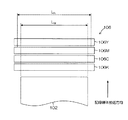
図11は、ヘッドモジュール142‐jのノズル配列を示す平面透視図である。同図に示すように、各ヘッドモジュール142‐jは、ノズル150が二次元状に並べられた構造を有し、かかるヘッドモジュール142‐jを備えたヘッドは、いわゆるマトリクスヘッドと呼ばれるものである。
FIG. 11 is a perspective plan view showing the nozzle arrangement of the head module 142-j. As shown in the figure, each head module 142-j has a structure in which the
図11に図示したヘッドモジュール142‐jは、副走査方向Sに対して角度αをなす列方向W、及び主走査方向Mに対して角度βをなす行方向Vに沿って多数のノズル150が並べられた構造を有し、主走査方向Mの実質的なノズル配置密度が高密度化されている。
The head module 142-j illustrated in FIG. 11 includes a number of
図11では、行方向Vに沿って並べられたノズル群(ノズル行)は符号152を付し、列方向Wに沿って並べられたノズル群(ノズル列)は符号154を付して図示されている。
In FIG. 11, nozzle groups (nozzle rows) arranged along the row direction V are denoted by
なお、ノズル150のマトリクス配置の他の例として、主走査方向Mに沿う行方向、及び主走査方向Mに対して斜め方向の列方向に沿って複数のノズル150を配置する構成が挙げられる。
As another example of the matrix arrangement of the
本例では、フルライン型の記録ヘッドを具備する形態を例示したが、記録媒体102に幅方向に短尺のインクジェットヘッドを走査させて同方向への画像記録を行い、同方向への一回の画像記録が終了すると、記録媒体102をインクジェットヘッドの走査方向と直交する方向へ所定量移動させて、次の領域に対してインクジェットヘッドを走査させながら画像記録を行う動作を繰り返して、記録媒体102の全域にわたって画像記録を行うシリアル方式を適用することも可能である。
In this example, an example in which a full-line type recording head is provided is illustrated. However, a short inkjet head is scanned in the width direction on the
本例に示すインクジェットヘッドの吐出方式は、圧電素子のたわみ変形を利用した圧電方式を適用してもよいし、ノズルと連通する液室内のインクの膜沸騰現象を利用したサーマル方式を適用してもよい。 The ink jet head ejection method shown in this example may be a piezoelectric method that utilizes the flexural deformation of the piezoelectric element, or a thermal method that utilizes the film boiling phenomenon of ink in the liquid chamber communicating with the nozzle. Also good.
圧電方式における記録素子は、ノズルと、ノズルと連通する圧力室と、圧力室を構成する壁に形成される圧電素子と、を含む形態がある。また、サーマル方式における記録素子は、ノズルと、ノズルと連通する液室と、液室内の液を加熱する加熱素子(ヒータ)と、を含む形態がある。 A recording element in the piezoelectric system has a form including a nozzle, a pressure chamber communicating with the nozzle, and a piezoelectric element formed on a wall constituting the pressure chamber. In addition, the recording element in the thermal method includes a nozzle, a liquid chamber communicating with the nozzle, and a heating element (heater) for heating the liquid in the liquid chamber.
(制御系の構成)
次に、本例に示すインクジェット記録装置100の制御系について説明する。図12は、インクジェット記録装置100の制御系の概略構成を示すブロック図である。
(Control system configuration)
Next, a control system of the ink
インクジェット記録装置100は、通信インターフェース170、システム制御部172、搬送制御部174、画像処理部176、ヘッド駆動部178を備えるとともに、画像メモリ180、ROM182を備えている。
The
通信インターフェース170は、ホストコンピュータ184から送られてくるラスター画像データを受信するインターフェース部である。通信インターフェース170は、USB(Universal Serial Bus)などのシリアルインターフェースを適用してもよいし、セントロニクスなどのパラレルインターフェースを適用してもよい。通信インターフェース170は、通信を高速化するためのバッファメモリ(不図示)を搭載してもよい。
The
システム制御部172は、中央演算処理装置(CPU)及びその周辺回路等から構成され、所定のプログラムに従ってインクジェット記録装置100の全体を制御する制御装置として機能するとともに、各種演算を行う演算装置として機能し、さらに、画像メモリ180及びROM182のメモリコントローラとして機能する。
The
すなわち、システム制御部172は、通信インターフェース170、搬送制御部174等の各部を制御し、ホストコンピュータ184との間の通信制御、画像メモリ180及びROM182の読み書き制御等を行うとともに、上記の各部を制御する制御信号を生成する。
That is, the
ホストコンピュータ184から送出された画像データは通信インターフェース170を介してインクジェット記録装置100に取り込まれ、画像処理部176によって所定の画像処理が施される。
Image data sent from the
画像処理部176は、画像データから印字制御用の信号を生成するための各種加工、補正などの処理を行う信号(画像)処理機能を有し、生成した印字データ(ドットデータ)をヘッド駆動部178に供給する制御部である。
The
上述したラスター画像データに対する記録画像の位置調整処理は、図12の画像処理部176において実行される。すなわち、通信インターフェース170は、図1のラスター画像データ入力部12及びむら評価関数取得部30に相当し、図12の画像処理部176は、図1の描画位置調整処理部14、濃度むら補正処理部16、吐出異常ノズル補正処理部18、ハーフトーン処理部20、ハーフトーン画像データ出力部22及び描画位置調整量算出部32に相当する。
The recorded image position adjustment process for the raster image data described above is executed by the
画像処理部176において所要の信号処理が施されると、該印字データ(ハーフトーン画像データ)に基づいて、ヘッド駆動部178を介してインクジェットヘッド140の吐出液滴量(打滴量)や吐出タイミングの制御が行われる。
When required signal processing is performed in the
これにより、所望のドットサイズやドット配置が実現される。なお、図12に示すヘッド駆動部178には、インクジェットヘッド140の駆動条件を一定に保つためのフィードバック制御系を含んでいてもよい。
Thereby, a desired dot size and dot arrangement are realized. The
搬送制御部174は、画像処理部176により生成された印字データに基づいて記録媒体102(図8,9参照)の搬送タイミング及び搬送速度を制御する。図12における搬送駆動部186は、記録媒体102を搬送する記録媒体搬送部104の駆動ローラ110(112)を駆動するモータが含まれており、搬送制御部174は該モータのドライバーとして機能している。
The
画像メモリ(一時記憶メモリ)180は、通信インターフェース170を介して入力された画像データを一旦格納する一時記憶手段としての機能や、ROM182に記憶されている各種プログラムの展開領域及びCPUの演算作業領域(例えば、画像処理部176の作業領域)としての機能を有している。画像メモリ180には、逐次読み書きが可能な揮発性メモリ(RAM)が用いられる。
An image memory (temporary storage memory) 180 functions as temporary storage means for temporarily storing image data input via the
ROM182は、システム制御部172のCPUが実行するプログラムや、装置各部の制御に必要な各種データ、制御パラメータなどが格納されており、システム制御部172を通じてデータの読み書きが行われる。ROM182は、半導体素子からなるメモリに限らず、ハードディスクなど磁気媒体を用いてもよい。また、外部インターフェースを備え、着脱可能な記憶媒体を用いてもよい。
The
読取装置128は、記録媒体102の搬送路上において画像(テストチャート)を読み取る撮像素子(CCDラインセンサ)と、該撮像素子から出力される読取信号にノズル除去や増幅、波形整形などの所定の信号処理を施す信号処理部と、を含む処理ブロックである。
The
読取装置128によって記録媒体102の余白等に形成されたテストチャートが読み取られ、その読取結果に基づいて各ノズルの吐出異常の有無が判断される。吐出異常が発生しているノズルは、吐出異常ノズルとして登録される。吐出異常ノズルが所定数を超えると、インクジェットヘッド140のメンテナンスが実行される。
A test chart formed in a margin or the like of the
読取装置128を備えるインクジェット記録装置100では、吐出異常ノズルの検出を定期的に行うことができ、吐出異常ノズルの情報を随時更新することができる。すなわち、画像形成ごと、ジョブ間、所定期間ごとにインクジェットヘッド140から吐出異常ノズル検出用のテストチャートを出力させ、読取装置128によって該テストチャートを読み取り、その読取結果に基づいて吐出異常ノズルを検出しうる。
In the ink
パラメータ記憶部190は、インクジェット記録装置100の動作に必要な各種制御パラメータが記憶されている。システム制御部172は、制御に必要なパラメータを適宜読み出すとともに、必要に応じて各種パラメータの更新(書換)を実行する。
The
パラメータ記憶部190は、上述したむら評価関数M(描画性能評価関数F)が記憶される記憶部や、吐出異常ノズル情報が記憶される記憶部として機能している。すなわち、通信インターフェース170を介して取得されたむら評価関数M(描画性能評価関数F)は、システム制御部172を介してパラメータ記憶部190に記憶され、画像処理部176における画像処理に応じて適宜読み出される。
The
プログラム格納部192は、インクジェット記録装置100を動作させるための制御プログラムが格納されている記憶手段である。システム制御部172(又は装置各部)は、装置各部の制御を実行する際にプログラム格納部192から必要な制御プログラムが読み出され、該制御プログラムは適宜実行される。
The
プログラム格納部192は、上述した記録媒体102上における記録画像の位置を調整する画像処理方法を実行するためのプログラムや、他の画像処理方法を実行するためのプログラムを格納することが可能である。
The
本例では、複数のノズルを具備するインクジェットヘッドからインク液滴を吐出させて記録媒体上にカラー画像を記録するインクジェット方式の画像記録を例示したが、本発明の適用範囲はこれに限定されず、記録素子としてLED素子を具備する記録ヘッドを用いた電子写真方式の画像記録や、他の方式の画像記録にも本発明を適用することが可能である。 In this example, ink-jet type image recording in which a color image is recorded on a recording medium by ejecting ink droplets from an ink-jet head having a plurality of nozzles is illustrated, but the scope of application of the present invention is not limited thereto. The present invention can also be applied to electrophotographic image recording using a recording head including an LED element as a recording element, and other types of image recording.
以上、本発明の実施形態に係る画像処理装置及び画像記録装置並びに画像処理方法について詳細に説明したが、上述した構成は本発明の趣旨を逸脱しない範囲で、適宜変更が可能である。 As described above, the image processing apparatus, the image recording apparatus, and the image processing method according to the embodiment of the present invention have been described in detail. However, the above-described configuration can be appropriately changed without departing from the gist of the present invention.
〔付記〕
上記に詳述した発明の実施形態についての記載から把握されるとおり、本明細書は少なくとも以下に示す発明を含む多様な技術思想の開示を含んでいる。
[Appendix]
As will be understood from the description of the embodiments of the invention described in detail above, the present specification includes disclosure of various technical ideas including at least the invention described below.
(発明1):記録ヘッドに具備された記録素子を動作させて記録される画像の描画性能を定量的に表す評価値を求めるための描画性能評価関数を、少なくとも一つ取得する描画性能評価関数取得手段と、複数の画素から構成される多階調の画像を表すラスター画像データを取得するラスター画像データ取得部と、前記取得されたラスター画像データに対して、前記取得された描画性能評価関数により求められた評価値が最良の描画性能を示すように、記録画像の記録媒体上における位置を算出する描画位置算出手段と、前記算出された記録媒体上の位置に画像が記録されるように、前記ラスター画像データを調整する描画位置調整手段と、を備えたことを特徴とする画像処理装置。 (Invention 1): A drawing performance evaluation function for obtaining at least one drawing performance evaluation function for obtaining an evaluation value quantitatively representing the drawing performance of an image recorded by operating a recording element provided in the recording head. An acquisition unit; a raster image data acquisition unit that acquires raster image data representing a multi-tone image composed of a plurality of pixels; and the acquired drawing performance evaluation function for the acquired raster image data. A drawing position calculating means for calculating a position of the recorded image on the recording medium, and an image is recorded at the calculated position on the recording medium so that the evaluation value obtained by An image processing apparatus comprising: a drawing position adjusting unit that adjusts the raster image data.
本発明によれば、ラスター画像データに対して、描画性能を定量的に表す評価値を算出するための描画性能関数が適用されて、当該描画性能関数による評価値が最良の描画性能を示すように記録媒体上の記録画像の位置が算出され、当該算出された位置に記録画像が記録されるようにラスター画像データが調整されるので、各種のむらが抑制された好ましい画像記録を行うことが可能である。 According to the present invention, a rendering performance function for calculating an evaluation value that quantitatively represents rendering performance is applied to raster image data so that the evaluation value based on the rendering performance function indicates the best rendering performance. Since the position of the recorded image on the recording medium is calculated and the raster image data is adjusted so that the recorded image is recorded at the calculated position, it is possible to perform preferable image recording with various irregularities suppressed. It is.
記録ヘッドとして、複数のノズルが具備されるインクジェットヘッドを適用することができる。インクジェットヘッドを備える形態における「記録素子」は、液滴を吐出するノズルと、ノズルと連通する圧力室と、圧力室を加圧する加圧素子と、を含む形態がある。 As the recording head, an inkjet head having a plurality of nozzles can be applied. The “recording element” in the form including the ink jet head includes a form including a nozzle for ejecting liquid droplets, a pressure chamber communicating with the nozzle, and a pressure element for pressurizing the pressure chamber.
ラスター画像データは、記録画像を構成する画素の濃度値が多階調で表されたデジタル形式のデータが含まれる。ラスター画像データを処理対象とすることで、ラスター画像データに含まれる階調値(濃度値、画素値)を描画性能の評価において考慮することができる。 The raster image data includes digital format data in which the density values of the pixels constituting the recorded image are expressed in multiple gradations. By setting the raster image data as a processing target, it is possible to consider the gradation values (density values and pixel values) included in the raster image data in the evaluation of the drawing performance.
描画性能評価関数とは、描画性能を低下させる要因の出現度合い、及び当該要因の補正性能を表す評価関数であり、描画性能評価関数の評価値に応じて描画性能を低下させる程度が把握される。 The drawing performance evaluation function is an evaluation function representing the degree of appearance of a factor that degrades drawing performance and the correction performance of the factor, and the degree to which the drawing performance is reduced according to the evaluation value of the drawing performance evaluation function is grasped. .
取得された描画性能評価関数が記憶される記憶手段を備える態様が好ましい。 It is preferable that the storage unit stores the acquired drawing performance evaluation function.
(発明2):発明1に記載の画像処理装置において、前記調整されたラスター画像データに対して、ハーフトーン処理を施すことを特徴とする。
(Invention 2): The image processing apparatus according to
かかる態様におけるハーフトーン処理とは、多階調で表された画素値(濃度値)を二値又は多値のドットデータに変換する処理である。 The halftone process in this aspect is a process for converting pixel values (density values) expressed in multiple gradations into binary or multivalued dot data.
(発明3):発明1又は2に記載の画像処理装置において、前記描画性能評価関数取得手段は、各画素の階調値に応じて算出される前記描画性能評価関数を取得することを特徴とする。
(Invention 3): In the image processing apparatus according to
かかる態様によれば、各画素の階調値が考慮された好ましい描画性能の評価がされる。 According to this aspect, the preferable drawing performance is evaluated in consideration of the gradation value of each pixel.
ここでいう「階調値」には、画素値、濃度値と呼ばれる値が含まれる。 The “gradation value” here includes values called pixel values and density values.
(発明4):発明1から3のいずれか1項に記載の画像処理装置において、前記描画性能評価関数取得手段は、記録媒体上の位置をパラメータとする前記描画性能評価関数を取得することを特徴とする。
(Invention 4): In the image processing apparatus according to any one of
かかる態様によれば、記録媒体上の位置を変えながら描画性能評価関数の評価値を算出し、評価値を比較して最良の描画性能となる記録媒体上の位置を求めることが可能となる。 According to this aspect, it is possible to calculate the evaluation value of the drawing performance evaluation function while changing the position on the recording medium and compare the evaluation value to obtain the position on the recording medium that provides the best drawing performance.
(発明5):発明1から4のいずれかに記載の画像処理装置において、前記描画位置算出手段は、複数の前記描画性能評価関数が合成された合成描画性能評価関数により求められた評価値が最良の描画性能を示すように記録画像の記録媒体上における位置を算出することを特徴とする。
(Invention 5): In the image processing device according to any one of
かかる態様によれば、描画性能を低下させる要因が複数存在する場合にも、当該複数の要因の相関が考慮された好ましい描画性能の評価がされる。 According to this aspect, even when there are a plurality of factors that lower the drawing performance, the preferable drawing performance is evaluated in consideration of the correlation between the plurality of factors.
(発明6):発明1から5のいずれかに記載の画像処理装置において、前記描画性能評価関数取得手段は、記録画像における濃度むらの情報、及び前記濃度むらの補正性能から算出される第1の描画性能評価関数を取得することを特徴とする。
(Invention 6): In the image processing apparatus according to any one of
かかる態様によれば、記録画像に発生する濃度むらに起因する描画性能の低下が抑制された好ましい記録画像を得ることができる。 According to this aspect, it is possible to obtain a preferable recorded image in which a decrease in drawing performance due to density unevenness occurring in the recorded image is suppressed.
「記録画像における濃度むら」には、記録ヘッドの固体差に起因する濃度むらが含まれる。 “Density unevenness in a recorded image” includes density unevenness caused by a solid difference of a recording head.
記録ヘッドの固体差の要因として、記録素子の記録特性のばらつきや、記録ヘッドの組み立て等のばらつきなどに起因するものが挙げられる。 As a cause of the individual difference of the recording head, there are causes caused by a variation in recording characteristics of the recording element, a variation in assembly of the recording head, and the like.
(発明7):発明1から6のいずれかに記載の画像処理装置において、前記描画性能評価関数取得手段は、前記記録ヘッド内の異常記録素子の情報、及び前記異常記録素子の補正性能から算出される第2の描画性能評価関数を取得することを特徴とする。
(Invention 7): In the image processing apparatus according to any one of
かかる態様によれば、異常記録素子に起因する描画性能を低下が抑制された好ましい記録画像を得ることができる。 According to this aspect, it is possible to obtain a preferable recorded image in which a reduction in drawing performance due to the abnormal recording element is suppressed.
「異常記録素子」には、記録を行うことができない記録素子、及び記録はできるものの正常な動作をできない記録素子が含まれる。 The “abnormal recording element” includes a recording element that cannot perform recording and a recording element that can perform recording but cannot operate normally.
(発明8):発明1から7のいずれかに記載の画像処理装置において、前記描画性能評価関数取得手段は、画像記録中の振動により発生する記録画像における濃度むらの情報から算出される第3の描画性能評価関数を取得することを特徴とする。
(Invention 8): In the image processing apparatus according to any one of
かかる態様によれば、画像記録中の振動に起因する描画性能の低下が抑制された好ましい記録画像を得ることができる。 According to this aspect, it is possible to obtain a preferable recorded image in which a decrease in drawing performance due to vibration during image recording is suppressed.
(発明9):発明8に記載の画像処理装置において、前記描画位置算出手段は、前記第1の描画性能評価関数、及び前記第2の描画性能評価関数、前記第3の描画性能評価関数を合成した第4の描画性能評価関数により求められた評価値が最良の描画性能を示すように記録画像の記録媒体上における位置を算出することを特徴とする。
(Invention 9): In the image processing apparatus according to
かかる態様によれば、記録画像における濃度むらに起因する描画性能の低下、異常記録素子に起因する描画性能の低下、及び画像記録中の振動に起因する描画性能の低下が考慮され、それぞれの相関が考慮された描画性能の評価が可能となる。 According to such an aspect, a decrease in drawing performance due to density unevenness in a recorded image, a decrease in drawing performance due to an abnormal recording element, and a decrease in drawing performance due to vibration during image recording are considered, and the respective correlations are considered. It is possible to evaluate the drawing performance considering the above.
(発明10):発明1から9のいずれかに記載の画像処理装置において、前記描画位置算出手段は、1枚の記録媒体に複数の記録画像を記録する際に、記録画像ごとに位置を算出することを特徴とする。
(Invention 10): In the image processing device according to any one of
かかる態様によれば、描画性能を低下させる要因を避ける際に、個別の記録画像についての調整とすることができ、描画性能を低下させる要因が多岐にわたり複雑な場合にも対応が可能となる。 According to this aspect, when a factor that lowers drawing performance is avoided, adjustments can be made for individual recorded images, and it is possible to cope with a variety of complicated factors that reduce drawing performance.
(発明11):発明1から9のいずれかに記載の画像処理装置において、前記描画位置算出手段は、1枚の記録媒体に複数の記録画像を記録する際に、前記複数の記録画像全体の位置を算出することを特徴とする。
(Invention 11): In the image processing device according to any one of
かかる態様によれば、描画性能を低下させる要因を避ける際に、必要最小限の画像の調整とすることができ、演算負荷の低減化に寄与する。 According to this aspect, it is possible to adjust the necessary minimum image when avoiding a factor that deteriorates the drawing performance, which contributes to a reduction in calculation load.
(発明12):発明1から11のいずれかに記載の画像処理装置において、前記調整後のラスター画像データに対して濃度むらに対する補正処理を施す濃度むら補正処理手段を備えたことを特徴とする。
(Invention 12): The image processing apparatus according to any one of
かかる態様によれば、濃度むらが補正された好ましい画像記録が実現される。 According to this aspect, preferable image recording in which density unevenness is corrected is realized.
(発明13):発明1から12のいずれかに記載の画像処理装置において、前記調整後のラスター画像データに対して前記異常記録素子に対する補正処理を施す異常記録素子補正処理手段を備えたことを特徴とする。
(Invention 13): The image processing apparatus according to any one of
かかる態様によれば、異常記録素子に起因する描画性能の低下が補正された好ましい画像記録が実現される。 According to this aspect, preferable image recording in which a decrease in drawing performance due to the abnormal recording element is corrected is realized.
(発明14):記録ヘッドに具備された記録素子を動作させて記録される画像の描画性能を定量的に表す評価値を算出するための描画性能評価関数を、少なくとも一つ取得する描画性能評価関数取得手段と、複数の画素から構成される多階調の画像を表すラスター画像データを取得するラスター画像データ取得部と、前記取得されたラスター画像データに対して、前記取得された描画性能評価関数により求められた評価値が最良の描画性能を示すように記録画像の記録媒体上における位置を算出する描画位置算出手段と、前記算出された記録媒体上の位置に画像が記録されるように、前記ラスター画像データを調整する描画位置調整手段と、前記調整されたラスターイメージに基づいて、記録媒体上に記録画像を記録するように前記記録ヘッドに具備される前記記録素子を動作させる記録制御手段と、を備えたことを特徴とする画像記録装置。 (Invention 14): Drawing performance evaluation for obtaining at least one drawing performance evaluation function for calculating an evaluation value quantitatively representing the drawing performance of an image recorded by operating a recording element provided in the recording head A function acquisition unit, a raster image data acquisition unit that acquires raster image data representing a multi-gradation image composed of a plurality of pixels, and the acquired drawing performance evaluation for the acquired raster image data Drawing position calculation means for calculating the position of the recorded image on the recording medium so that the evaluation value obtained by the function shows the best drawing performance, and the image is recorded at the calculated position on the recording medium. A drawing position adjusting means for adjusting the raster image data; and the recording head so as to record a recorded image on a recording medium based on the adjusted raster image. The image recording apparatus characterized by comprising a recording control means for operating the printing elements provided in the.
本発明に係る画像記録の一態様として、インクジェットヘッドからインク液滴を吐出させて、記録媒体上にカラー画像を記録するインクジェット記録装置が挙げられる。 As one aspect of the image recording according to the present invention, there is an ink jet recording apparatus that records a color image on a recording medium by ejecting ink droplets from an ink jet head.
(発明15):記録ヘッドに具備された記録素子を動作させて記録される画像の描画性能を定量的に表す評価値を算出するための描画性能評価関数を、少なくとも一つ取得する描画性能評価関数取得工程と、複数の画素から構成される多階調の画像を表すラスター画像データを取得するラスター画像データ取得工程と、前記取得されたラスター画像データに対して、前記取得された描画性能評価関数により求められた評価値が最良の描画性能を示すように記録画像の記録媒体上における位置を算出する描画位置算出工程と、前記算出された記録媒体上の位置に画像が記録されるように、前記ラスター画像データを調整する描画位置調整工程と、を含むことを特徴とする画像処理方法。 (Invention 15): Drawing performance evaluation for obtaining at least one drawing performance evaluation function for calculating an evaluation value that quantitatively represents the drawing performance of an image recorded by operating a recording element provided in the recording head A function acquisition step, a raster image data acquisition step of acquiring raster image data representing a multi-tone image composed of a plurality of pixels, and the acquired drawing performance evaluation for the acquired raster image data A drawing position calculating step for calculating the position of the recorded image on the recording medium so that the evaluation value obtained by the function shows the best drawing performance, and the image is recorded at the calculated position on the recording medium. And a drawing position adjusting step for adjusting the raster image data.
本発明において、調整されたラスター画像データに対して、ハーフトーン処理を施すハーフトーン工程を含む態様が好ましい。 In the present invention, an aspect including a halftone process for performing halftone processing on the adjusted raster image data is preferable.
また、描画位置算出工程は、前記記憶されている描画性能評価関数により求められた評価値が最小値を示すように記録画像の記録媒体上における位置を算出する態様が好ましい。 The drawing position calculating step preferably calculates the position of the recorded image on the recording medium so that the evaluation value obtained by the stored drawing performance evaluation function shows a minimum value.
また、描画性能評価関数取得工程は、各画素の階調値に応じて算出される少なくとも一つの前記描画性能評価関数を取得する態様が好ましい。 Further, it is preferable that the drawing performance evaluation function acquisition step acquires at least one drawing performance evaluation function calculated according to the gradation value of each pixel.
さらに、描画位置算出工程は、複数の前記描画性能評価関数が合成された合成描画性能評価関数により求められた評価値が最良の描画性能を示すように記録画像の記録媒体上における位置を算出する態様が好ましい。 Further, the drawing position calculation step calculates the position of the recorded image on the recording medium so that the evaluation value obtained by the combined drawing performance evaluation function obtained by combining the plurality of drawing performance evaluation functions shows the best drawing performance. Embodiments are preferred.
また、描画性能評価関数取得手段は、記録画像における濃度むらの情報、及び前記濃度むらの補正性能から算出される第1の描画性能評価関数を取得する態様や、前記記録ヘッド内の異常記録素子の情報、及び前記異常記録素子の補正性能から算出される第2の描画性能評価関数を取得する態様、画像記録中の振動により発生する記録画像における濃度むらの情報から算出される第3の描画性能評価関数を取得する態様、第1の描画性能評価関数、及び第2の描画性能評価関数、第3の描画性能評価関数を合成した第4の描画性能評価関数により求められた評価値が最良の描画性能を示すように記録画像の記録媒体上における位置を算出する態様が好ましい。 Further, the drawing performance evaluation function acquisition unit acquires a first drawing performance evaluation function calculated from density unevenness information in the recorded image and the density unevenness correction performance, or an abnormal recording element in the recording head. And a second drawing performance evaluation function calculated from the correction performance of the abnormal recording element, a third drawing calculated from density unevenness information in a recorded image generated by vibration during image recording The evaluation value obtained by the aspect of acquiring the performance evaluation function, the first drawing performance evaluation function, the second drawing performance evaluation function, and the fourth drawing performance evaluation function obtained by synthesizing the third drawing performance evaluation function is the best. It is preferable to calculate the position of the recorded image on the recording medium so as to show the drawing performance.
また、描画位置算出手段は、1枚の記録媒体に複数の記録画像を記録する際に、記録画像ごとに位置を算出する態様が好ましい。 Further, it is preferable that the drawing position calculating unit calculates the position for each recording image when recording a plurality of recording images on one recording medium.
一方、描画位置算出手段は、1枚の記録媒体に複数の記録画像を記録する際に、前記複数の記録画像全体の位置を算出する態様も好ましい。 On the other hand, it is also preferable that the drawing position calculation means calculates the positions of the plurality of recorded images when recording the plurality of recorded images on one recording medium.
調整後のラスター画像データに対して濃度むらに対する補正処理を施す濃度むら補正処理工程を含む態様や、調整後のラスター画像データに対して前記異常記録素子に対する補正処理を施す異常記録素子補正処理工程を含む態様が好ましい。 A mode including a density unevenness correction process for performing correction processing for density unevenness on the adjusted raster image data, or an abnormal recording element correction process for performing correction processing for the abnormal recording element on the adjusted raster image data The aspect containing is preferable.
10…画像処理装置、12…ラスター画像データ入力部、14…描画位置調整処理部、16…濃度むら補正処理部、18…吐出異常ノズル補正処理部、20…ハーフトーン処理部、22…ハーフトーン画像データ出力部、30…むら評価関数取得部、32…描画位置調整量算出部、60…記録ヘッド、62,150…ノズル、66,102…記録媒体、68…記録画像、100…インクジェット記録装置、106…印字部、106K,106C,106M,106Y,140…インクジェットヘッド、170…通信インターフェース、172…システム制御部、176…画像処理部、190…パラメータ記憶部 DESCRIPTION OF SYMBOLS 10 ... Image processing apparatus, 12 ... Raster image data input part, 14 ... Drawing position adjustment process part, 16 ... Density unevenness correction process part, 18 ... Discharge abnormal nozzle correction process part, 20 ... Halftone process part, 22 ... Halftone Image data output unit, 30 ... unevenness evaluation function acquisition unit, 32 ... drawing position adjustment amount calculation unit, 60 ... recording head, 62, 150 ... nozzle, 66, 102 ... recording medium, 68 ... recorded image, 100 ... inkjet recording apparatus , 106 ... printing unit, 106K, 106C, 106M, 106Y, 140 ... inkjet head, 170 ... communication interface, 172 ... system control unit, 176 ... image processing unit, 190 ... parameter storage unit
Claims (15)
複数の画素から構成される多階調の画像を表すラスター画像データを取得するラスター画像データ取得部と、
前記取得されたラスター画像データに対して、前記取得された描画性能評価関数により求められた評価値が最良の描画性能を示すように、記録画像の記録媒体上における位置を算出する描画位置算出手段と、
前記算出された記録媒体上の位置に画像が記録されるように、前記ラスター画像データを調整する描画位置調整手段と、
を備えたことを特徴とする画像処理装置。 A drawing performance evaluation function acquisition means for acquiring at least one drawing performance evaluation function for obtaining an evaluation value that quantitatively represents the drawing performance of an image recorded by operating a recording element provided in the recording head;
A raster image data acquisition unit for acquiring raster image data representing a multi-tone image composed of a plurality of pixels;
A drawing position calculating means for calculating the position of the recorded image on the recording medium so that the evaluation value obtained by the acquired drawing performance evaluation function shows the best drawing performance for the acquired raster image data. When,
A drawing position adjusting means for adjusting the raster image data so that an image is recorded at the calculated position on the recording medium;
An image processing apparatus comprising:
複数の画素から構成される多階調の画像を表すラスター画像データを取得するラスター画像データ取得部と、
前記取得されたラスター画像データに対して、前記取得された描画性能評価関数により求められた評価値が最良の描画性能を示すように記録画像の記録媒体上における位置を算出する描画位置算出手段と、
前記算出された記録媒体上の位置に画像が記録されるように、前記ラスター画像データを調整する描画位置調整手段と、
前記調整されたラスターイメージに基づいて、記録媒体上に記録画像を記録するように前記記録ヘッドに具備される前記記録素子を動作させる記録制御手段と、
を備えたことを特徴とする画像記録装置。 A drawing performance evaluation function acquisition means for acquiring at least one drawing performance evaluation function for obtaining an evaluation value that quantitatively represents the drawing performance of an image recorded by operating a recording element provided in the recording head;
A raster image data acquisition unit for acquiring raster image data representing a multi-tone image composed of a plurality of pixels;
A drawing position calculating means for calculating a position of the recorded image on the recording medium so that the evaluation value obtained by the acquired drawing performance evaluation function indicates the best drawing performance with respect to the acquired raster image data; ,
Drawing position adjusting means for adjusting the raster image data so that an image is recorded at the calculated position on the recording medium;
Recording control means for operating the recording element provided in the recording head to record a recording image on a recording medium based on the adjusted raster image;
An image recording apparatus comprising:
複数の画素から構成される多階調の画像を表すラスター画像データを取得するラスター画像データ取得工程と、
前記取得されたラスター画像データに対して、前記取得された描画性能評価関数により求められた評価値が最良の描画性能を示すように記録画像の記録媒体上における位置を算出する描画位置算出工程と、
前記算出された記録媒体上の位置に画像が記録されるように、前記ラスター画像データを調整する描画位置調整工程と、
を含むことを特徴とする画像処理方法。 A drawing performance evaluation function acquisition step for acquiring at least one drawing performance evaluation function for obtaining an evaluation value that quantitatively represents the drawing performance of an image recorded by operating a recording element provided in the recording head;
A raster image data acquisition step of acquiring raster image data representing a multi-tone image composed of a plurality of pixels;
A drawing position calculating step for calculating a position of the recorded image on the recording medium such that an evaluation value obtained by the acquired drawing performance evaluation function indicates the best drawing performance for the acquired raster image data; ,
A drawing position adjusting step of adjusting the raster image data so that an image is recorded at the calculated position on the recording medium;
An image processing method comprising:
Priority Applications (1)
| Application Number | Priority Date | Filing Date | Title |
|---|---|---|---|
| JP2011026425A JP2012166346A (en) | 2011-02-09 | 2011-02-09 | Image processor, image recorder and image processing method |
Applications Claiming Priority (1)
| Application Number | Priority Date | Filing Date | Title |
|---|---|---|---|
| JP2011026425A JP2012166346A (en) | 2011-02-09 | 2011-02-09 | Image processor, image recorder and image processing method |
Publications (2)
| Publication Number | Publication Date |
|---|---|
| JP2012166346A true JP2012166346A (en) | 2012-09-06 |
| JP2012166346A5 JP2012166346A5 (en) | 2013-10-03 |
Family
ID=46971002
Family Applications (1)
| Application Number | Title | Priority Date | Filing Date |
|---|---|---|---|
| JP2011026425A Withdrawn JP2012166346A (en) | 2011-02-09 | 2011-02-09 | Image processor, image recorder and image processing method |
Country Status (1)
| Country | Link |
|---|---|
| JP (1) | JP2012166346A (en) |
Cited By (4)
| Publication number | Priority date | Publication date | Assignee | Title |
|---|---|---|---|---|
| JP2016198967A (en) * | 2015-04-10 | 2016-12-01 | キヤノン株式会社 | Image recording device and control method for the same |
| JPWO2019012989A1 (en) * | 2017-07-12 | 2020-04-16 | 富士フイルム株式会社 | Image forming apparatus and image forming method |
| US10744774B2 (en) | 2018-03-15 | 2020-08-18 | Kyocera Document Solutions Inc. | Inkjet recording apparatus |
| CN118295608A (en) * | 2024-04-02 | 2024-07-05 | 广州彩色新电子技术有限公司 | Printer state monitoring and evaluating method and system |
-
2011
- 2011-02-09 JP JP2011026425A patent/JP2012166346A/en not_active Withdrawn
Cited By (4)
| Publication number | Priority date | Publication date | Assignee | Title |
|---|---|---|---|---|
| JP2016198967A (en) * | 2015-04-10 | 2016-12-01 | キヤノン株式会社 | Image recording device and control method for the same |
| JPWO2019012989A1 (en) * | 2017-07-12 | 2020-04-16 | 富士フイルム株式会社 | Image forming apparatus and image forming method |
| US10744774B2 (en) | 2018-03-15 | 2020-08-18 | Kyocera Document Solutions Inc. | Inkjet recording apparatus |
| CN118295608A (en) * | 2024-04-02 | 2024-07-05 | 广州彩色新电子技术有限公司 | Printer state monitoring and evaluating method and system |
Similar Documents
| Publication | Publication Date | Title |
|---|---|---|
| JP5311688B2 (en) | Density unevenness correction value calculation method, image processing method, and image processing apparatus | |
| EP2842749B1 (en) | Image processing method, image processing device, image forming device, and inkjet recording device | |
| JP4721118B2 (en) | Image processing apparatus and method, and image forming apparatus and method | |
| JP4736766B2 (en) | Printing apparatus, printing program, printing method and image processing apparatus, image processing program, image processing method, and recording medium recording the program | |
| US6830306B2 (en) | Compensating for drop volume variation in an inkjet printer | |
| JP4419947B2 (en) | Printing apparatus, printing apparatus control program, printing apparatus control method, printing data generation apparatus, printing data generation program, and printing data generation method | |
| JP3890220B2 (en) | Recording apparatus and recording method | |
| JP4428362B2 (en) | Printing apparatus, printing program, printing method and printing control apparatus, printing control program, printing control method, and recording medium recording the program | |
| US9064327B2 (en) | Image processing method, image processing device, image forming device and inkjet recording device | |
| KR20070024421A (en) | Printing apparatus, a recording media having recorded thereon a printing program, printing method, image processing apparatus, a recording media having recorded thereon an image processing program, and image processing method | |
| JP6220029B2 (en) | Inkjet printing system, undischarge correction method and program thereof | |
| JP6398199B2 (en) | Print control apparatus, print control method, and print control program | |
| JP2014100795A (en) | Image processing apparatus, recording device, and image processing method | |
| JP5843400B2 (en) | Image processing apparatus, method and program, and ink jet recording apparatus | |
| JP2007237398A (en) | System and method for recording image | |
| JP2012066516A (en) | Image recording apparatus, and device, method, and program for calculating correction value | |
| JP2009241564A (en) | Image recording device, image recording method, ejection characteristic inspection chart, and ejection characteristic inspection method | |
| JP6018994B2 (en) | Inkjet printing system, undischarge correction method and program thereof | |
| JP6113102B2 (en) | Position misalignment detection method, image position misalignment correction method, streak unevenness correction table creation method, and streak unevenness correction method | |
| JP2012166346A (en) | Image processor, image recorder and image processing method | |
| JP2014072851A (en) | Image recorder, image processing method and image processing program | |
| JP5702621B2 (en) | Image recording apparatus and image recording method | |
| JP6109110B2 (en) | Unevenness correction apparatus and unevenness correction method | |
| JP2007290171A (en) | Method for evaluating improvement of printing quality of image, and apparatus and program for evaluating improvement of printing quality of image | |
| JP2013180564A (en) | Image forming method and image forming apparatus |
Legal Events
| Date | Code | Title | Description |
|---|---|---|---|
| A621 | Written request for application examination |
Free format text: JAPANESE INTERMEDIATE CODE: A621 Effective date: 20130702 |
|
| A521 | Written amendment |
Free format text: JAPANESE INTERMEDIATE CODE: A523 Effective date: 20130820 |
|
| A761 | Written withdrawal of application |
Free format text: JAPANESE INTERMEDIATE CODE: A761 Effective date: 20131209 |