JP2012166235A - Press molding method and press molding device - Google Patents
Press molding method and press molding device Download PDFInfo
- Publication number
- JP2012166235A JP2012166235A JP2011028971A JP2011028971A JP2012166235A JP 2012166235 A JP2012166235 A JP 2012166235A JP 2011028971 A JP2011028971 A JP 2011028971A JP 2011028971 A JP2011028971 A JP 2011028971A JP 2012166235 A JP2012166235 A JP 2012166235A
- Authority
- JP
- Japan
- Prior art keywords
- punch
- die
- temperature
- press molding
- molding apparatus
- Prior art date
- Legal status (The legal status is an assumption and is not a legal conclusion. Google has not performed a legal analysis and makes no representation as to the accuracy of the status listed.)
- Withdrawn
Links
Images
Abstract
Description
本発明は、パンチに形成された凸部と、ダイスに形成された凹部とによって、軟化させた素材を挟持しつつ押圧し、該素材にプレス成形を施すプレス成形方法およびプレス成形装置の技術に関する。 The present invention relates to a technology of a press molding method and a press molding apparatus in which a softened material is sandwiched and pressed by a convex portion formed on a punch and a concave portion formed on a die, and the material is press-molded. .
従来から、例えばモータコア(より具体的には、ステーターなど。以下、同じ。)などのような、積層構造からなる部品については、プレス成形によって成形されることが多い。
より具体的には、前記モータコアは、積層された複数枚の電磁鋼板をカシメにより固定保持し、その後、加熱して全体的に軟化させた後、パンチに形成された凸部と、ダイスに形成された凹部とによって挟持しながら押圧する(プレス成形する)ことで、所定の形状に打ち抜かれて成形されるのである。
Conventionally, a component having a laminated structure such as a motor core (more specifically, a stator or the like; hereinafter the same) is often formed by press molding.
More specifically, the motor core is formed by forming a plurality of laminated electromagnetic steel plates by caulking, then heating and softening the entire plate, and then forming convex portions and punches formed on the punch. By being pressed (press-molded) while being sandwiched between the formed recesses, it is punched into a predetermined shape and molded.
ところで、このようなプレス成形される成形品(モータコア)の品質向上を図ることは、該モータコアが備えられたモータの効率を向上させるための有効的な一手段である。
そして、モータコアのプレス成形においては、従来から品質向上を図るための様々な対策が施されており、その一例として、パンチおよびダイスの温度を同一、且つ一定温度に保持しつつ、プレス加工を行う技術が知られている(例えば、「特許文献1」を参照。)。
より具体的には、例えば、プレス成形装置において、パンチとダイスとを各々固定保持するパンチホルダーとダイスホルダーとに対して、オイル循環機能をそれぞれ設け、これらオイル循環機能を介して、所定の温度に温調された循環オイルを循環させて、これらパンチホルダーとダイスホルダーとを同一温度に調節することで、前記パンチとダイスとの温度を同一且つ一定に保持し、プレス加工を行う技術が知られている。
また、例えば、プレス成形装置全体を一定温度に保温された恒温室内に配設することで、前記パンチとダイスとの温度を同一且つ一定に保持し、プレス加工を行う技術が知られている。
By the way, improving the quality of a press-molded product (motor core) is an effective means for improving the efficiency of a motor provided with the motor core.
In the press molding of the motor core, various countermeasures have been conventionally taken to improve the quality. As an example, press working is performed while maintaining the punch and die temperatures at the same and constant temperature. A technique is known (see, for example, “Patent Document 1”).
More specifically, for example, in a press molding apparatus, an oil circulation function is provided for each of a punch holder and a die holder for fixing and holding the punch and the die, and a predetermined temperature is set via the oil circulation function. The technology is known in which the temperature of the punch and the die holder is adjusted to the same temperature by circulating the temperature-controlled circulating oil to keep the temperature of the punch and the die constant and constant. It has been.
Further, for example, a technique is known in which the entire press molding apparatus is placed in a temperature-controlled room kept at a constant temperature, so that the temperature of the punch and the die is kept the same and constant and press working is performed.
このような、パンチおよびダイスの温度を同一且つ一定温度に保持しつつ、プレス加工を行う技術を用いれば、前記パンチとダイスとの温度差によって引き起こされる悪影響を取り除いて、成形品であるモータコアの品質を向上させることが可能となる。
即ち、プレス成形時における、パンチの凸部の外周面と、ダイスの凹部の内周面とによって形成される隙間(以下、「抜きクリアランス」と記載する)が増加すると、前記凸部と凹部とによって素材(本例においては、積層された電磁鋼板)に加えられる剪断応力が低下し、プレス成形される成形品(本例においては、モータコア)には「加工歪み」が発生するが、前述した技術を用いれば、前記パンチとダイスとの温度差により熱膨張量の差が生じて「抜きクリアランス」が増加するようなこともなく、成形品であるモータコアの品質を向上させることが可能である。
しかし、パンチおよびダイスの「抜きクリアランス」が、当初は適正な値に調整されていたとしても、プレス成形が続けられるに従って、パンチの凸部とダイスの凹部との摩耗が進行し、「抜きクリアランス」が徐々に増加する。その結果、成形品であるモータコアには「加工歪み」が発生するため、向上させた該モータコアの品質を、長期間に渡って確実に維持することは困難であった。
また、現実的な問題として、これらパンチやダイスの製作誤差や、プレス装置に組付ける際の組付け誤差などによるバラツキを考慮した場合、「抜きクリアランス」については、前記バラツキを十分に吸収し得る大きさをもって、予め設定する必要があり、成形品であるモータコアの品質向上を図るため、前記「抜きクリアランス」の大きさを極力小さくするにも限度があった。
By using such a technique for pressing while maintaining the punch and die temperatures at the same and constant temperature, the adverse effect caused by the temperature difference between the punch and the die is eliminated, and the motor core that is a molded product is removed. Quality can be improved.
That is, when a gap formed by the outer peripheral surface of the convex portion of the punch and the inner peripheral surface of the concave portion of the die during press molding increases (hereinafter referred to as “punch clearance”), the convex portion and the concave portion As a result, the shear stress applied to the material (in this example, laminated magnetic steel sheets) is reduced, and a “working distortion” occurs in the press-formed product (in this example, the motor core). If the technology is used, it is possible to improve the quality of the motor core, which is a molded product, without causing a difference in thermal expansion due to the temperature difference between the punch and the die and increasing the “punch clearance”. .
However, even if the punch and die “punch clearance” was initially adjusted to an appropriate value, as the press molding continued, the wear of the punch convex portion and the die concave portion progressed, and the “punch clearance” Will gradually increase. As a result, since “processing distortion” occurs in the molded motor core, it has been difficult to reliably maintain the improved quality of the motor core over a long period of time.
Moreover, as a practical problem, when considering variations due to manufacturing errors of these punches and dies, assembling errors when assembling to the press machine, etc., the “clearance” can sufficiently absorb the variations. In order to improve the quality of the motor core, which is a molded product, it is necessary to set the size in advance, and there has been a limit to reducing the size of the “pull-out clearance” as much as possible.
本発明は、以上に示した現状の問題点を鑑みてなされたものであり、パンチに形成された凸部と、ダイスに形成された凹部とによって、軟化させた素材を挟持しつつ押圧し、該素材にプレス成形を施すプレス成形方法およびプレス成形装置であって、プレス成形時において、前記凸部の外周面と、前記凹部の内周面との間に形成される隙間(「抜きクリアランス」)の大きさを極力小さくすることで、成形品の品質向上を図ったプレス成形方法およびプレス成形装置を提供することを課題とする。 The present invention has been made in view of the above-described current problems, and presses while holding a softened material between a convex portion formed on a punch and a concave portion formed on a die, A press molding method and a press molding apparatus for performing press molding on the material, and a gap formed between the outer peripheral surface of the convex portion and the inner peripheral surface of the concave portion ("punch clearance") during press molding It is an object of the present invention to provide a press molding method and a press molding apparatus that improve the quality of a molded product by minimizing the size of).
本発明の解決しようとする課題は以上の如くであり、次にこの課題を解決するための手段を説明する。 The problem to be solved by the present invention is as described above. Next, means for solving the problem will be described.
即ち、請求項1においては、パンチと、該パンチに対向して配設されるダイスと、を備え、前記パンチにおいて前記ダイスとの対向側には凸部が形成され、前記ダイスにおいて前記パンチとの対向側には凹部が形成され、前記パンチおよび前記ダイスが対向方向に沿って相対的に近接離間するように、前記パンチおよび前記ダイスの少なくとも一方が移動可能に設けられ、前記パンチおよび前記ダイスが近接することで、前記凸部が前記凹部に隙間を有して嵌合されるプレス成形装置を用いたプレス成形方法であって、前記パンチおよび/または前記ダイスの温度を変更し、前記パンチと前記ダイスとの温度差を調節することで、前記凸部と前記凹部との間の隙間を調節するものである。 That is, according to the first aspect of the present invention, a punch and a die disposed opposite to the punch are provided, and a convex portion is formed on the side facing the die in the punch, and the punch includes A recess is formed on the opposite side of the punch, and at least one of the punch and the die is movably provided so that the punch and the die are relatively close to each other along the facing direction. Is a press molding method using a press molding apparatus in which the convex portion is fitted with a gap in the concave portion, the temperature of the punch and / or the die is changed, and the punch The gap between the convex part and the concave part is adjusted by adjusting the temperature difference between the convex part and the die.
請求項2においては、請求項1に記載のプレス成形方法であって、前記パンチと前記ダイスとの温度差の調節は、前記パンチおよび/または前記ダイスを加熱し、加熱された前記パンチおよび/または前記ダイスの温度を、所定の温度に保持することによって行われることによって行われるものである。 The press molding method according to claim 1, wherein the temperature difference between the punch and the die is adjusted by heating the punch and / or the die and heating the punch and / or the die. Alternatively, it is performed by maintaining the temperature of the die at a predetermined temperature.
請求項3においては、請求項1に記載のプレス成形方法であって、前記パンチと前記ダイスとの温度差の調節は、前記パンチおよび/または前記ダイスを冷却し、冷却された前記パンチおよび/または前記ダイスの温度を、所定の温度に保持することによって行われるものである。 The press molding method according to claim 1, wherein the temperature difference between the punch and the die is adjusted by cooling the punch and / or the die, and the cooled punch and / or Alternatively, it is performed by maintaining the temperature of the die at a predetermined temperature.
請求項4においては、パンチと、該パンチに対向して配設されるダイスと、を備え、前記パンチにおいて前記ダイスとの対向側には凸部が形成され、前記ダイスにおいて前記パンチとの対向側には凹部が形成され、前記パンチおよび前記ダイスが対向方向に沿って相対的に近接離間するように、前記パンチおよび前記ダイスの少なくとも一方が移動可能に設けられ、前記パンチおよび前記ダイスが近接することで、前記凸部が前記凹部に隙間を有して嵌合されるプレス成形装置であって、前記パンチおよび/または前記ダイスには温度調節機能がそれぞれ備えられ、該温度調節機能によって、前記パンチおよび/または前記ダイスの温度を変更し、前記パンチと前記ダイスとの温度差を調節することで、前記凸部と前記凹部との間の隙間を調節するものである。 According to a fourth aspect of the present invention, the punch includes a punch and a die disposed so as to face the punch, and a convex portion is formed on the side facing the die in the punch, and the die faces the punch. A recess is formed on the side, and at least one of the punch and the die is movably provided so that the punch and the die are relatively close to each other along the facing direction, and the punch and the die are close to each other. By doing so, the convex part is a press molding apparatus fitted with a gap in the concave part, the punch and / or the die is provided with a temperature adjustment function, respectively, by the temperature adjustment function, The gap between the convex portion and the concave portion is adjusted by changing the temperature of the punch and / or the die and adjusting the temperature difference between the punch and the die. It is intended to.
請求項5においては、請求項4に記載のプレス成形装置であって、前記温度調節機能は、前記パンチおよび/または前記ダイスを加熱する加熱手段と、前記パンチおよび/または前記ダイスの温度を検出する温度検出手段と、を有して構成されるものである。 5. The press molding apparatus according to claim 4, wherein the temperature adjusting function detects a heating means for heating the punch and / or the die, and a temperature of the punch and / or the die. Temperature detecting means.
請求項6においては、請求項4に記載のプレス成形装置であって、前記温度調節機能は、前記パンチおよび/または前記ダイスを冷却する冷却手段と、前記パンチおよび/または前記ダイスの温度を検出する温度検出手段と、を有して構成されるものである。 6. The press molding apparatus according to claim 4, wherein the temperature adjusting function detects a cooling means for cooling the punch and / or the die, and a temperature of the punch and / or the die. Temperature detecting means.
本発明の効果として、以下に示すような効果を奏する。 As effects of the present invention, the following effects can be obtained.
即ち、本発明におけるプレス成形方法およびプレス成形装置によれば、パンチに形成された凸部と、ダイスに形成された凹部とによって、軟化させた素材を挟持しつつ押圧し、該素材にプレス成形を施す際、前記凸部の外周面と、前記凹部の内周面との間に形成される隙間(「抜きクリアランス」)の大きさを極力小さくすることが可能となり、成形品の品質向上を図ることができる。 That is, according to the press molding method and the press molding apparatus of the present invention, the softened material is pressed and sandwiched between the convex portion formed on the punch and the concave portion formed on the die, and the material is press molded. , The size of the gap formed between the outer peripheral surface of the convex portion and the inner peripheral surface of the concave portion (“extraction clearance”) can be reduced as much as possible to improve the quality of the molded product. Can be planned.
次に、発明の実施の形態を説明する。 Next, embodiments of the invention will be described.
[プレス成形装置1(第一実施例)の全体構成]
先ず、本発明を具現化する、第一実施例におけるプレス成形装置1の全体的な構成について、図1を用いて説明する。
なお、以下の説明に関しては便宜上、図1の上下方向をプレス成形装置1の上下方向と規定して説明する。
[Overall configuration of press forming apparatus 1 (first embodiment)]
First, the overall configuration of a press forming apparatus 1 in the first embodiment embodying the present invention will be described with reference to FIG.
In addition, regarding the following description, for convenience, the vertical direction in FIG. 1 is described as the vertical direction of the press forming apparatus 1.
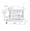
本実施例におけるプレス成形装置1は、パンチ2に形成された凸部2aと、ダイス3に形成された凹部3aとによって、軟化させた素材100を挟持しつつ押圧し、該素材100にプレス成形を施す装置である。
より具体的には、本実施例におけるプレス成形装置1は、パンチ2およびダイス3を個別に加熱し、あるいはパンチ2およびダイス3のうちの何れか一方を加熱して、両者間の温度差が所定の値となるように調節(温調)することによって、熱膨張後におけるパンチ2およびダイス3の膨張率の差を調節し、凸部2aの外周面と、凹部3aの内周面とによって形成される隙間(以下、「抜きクリアランス」と記載する)を極力小さな値とすることを可能にした装置である。
The press molding apparatus 1 according to the present embodiment presses the softened
More specifically, the press molding apparatus 1 in the present embodiment heats the punch 2 and the die 3 individually, or heats one of the punch 2 and the die 3, and the temperature difference between the two is increased. By adjusting (temperature control) so as to be a predetermined value, the difference in expansion coefficient between the punch 2 and the die 3 after thermal expansion is adjusted, and the outer peripheral surface of the
なお、本実施例においては、複数枚の電磁鋼板からなる積層体を素材100とし、成形品としてモータコア(より具体的には、ステーターなど。以下、同じ。)をプレス成形する場合について説明するが、本発明に係るプレス成形装置の加工対象とする素材および成形品は、これら素材100やモータコアに限定されるものではなく、およそプレス成形によって一般的に成形される成形品や、該成形品の基となる素材の全てを含むものである。
In the present embodiment, a case will be described in which a laminated body composed of a plurality of electromagnetic steel sheets is used as the
プレス成形装置1は、一対のパンチ2およびダイス3や、同じく一対のパンチホルダー21およびダイスホルダー31や、プレス成形装置1全体の運転を制御する制御装置4などを有して構成される。
The press molding apparatus 1 includes a pair of punches 2 and a die 3, a pair of
パンチ2およびダイス3は、素材100に対してプレス成形を行う際に、該素材100に直接当接される部位である。
パンチ2およびダイス3は、互いに対向して配設され、後述するように、パンチホルダー21およびダイスホルダー31を介して、対向方向(本実施例においては、上下方向。以下同じ。)に沿って相対的に近接離間するように、パンチ2およびダイス3の少なくとも一方が移動可能に設けられる。
The punch 2 and the die 3 are portions that are in direct contact with the
The punch 2 and the die 3 are arranged to face each other and, as will be described later, through the
パンチ2において、ダイス3との対向側の側面(本実施例においては、下面)には、下方に向かって突出する凸部2aが形成される。
一方、ダイス3において、パンチ2との対向側の側面(本実施例においては、上面)には、前記凸部2aの形状に即した凹部3aが形成される。
なお、これら凸部2aおよび凹部3aは、互いに嵌合可能に構成される。
In the punch 2, a
On the other hand, in the die 3, a
In addition, these
そして、これらパンチ2およびダイス3が、相対的に近接する方向に移動され、互いに当接された状態(以下、「型閉じ状態」と記載する)になることで、凸部2aは凹部3aの内周部(内周面によって囲まれた空間。以下同じ。)に嵌合される。
なお、前記「型閉じ状態」において、凸部2aの外周面と、凹部3aの内周面との間には、寸法値dからなる「抜きクリアランス」が形成される。
Then, when the punch 2 and the die 3 are moved in a relatively close direction and are brought into contact with each other (hereinafter referred to as “mold closed state”), the
In the “mold closed state”, a “pull-out clearance” having a dimension value d is formed between the outer peripheral surface of the
パンチホルダー21およびダイスホルダー31は、パンチ2およびダイス3を、各々固定保持しつつ、対向方向に沿って相対的に移動させる部位である。
パンチホルダー21およびダイスホルダー31は、上下方向(パンチ2およびダイス3に関する対向方向)に配設される。また、パンチホルダー21の下面には、パンチ2が、凸部2aを下方に向けた姿勢で着脱可能に固定保持され、ダイスホルダー31の上面には、ダイス3が、凹部3aを上方に向かって開口させた姿勢で着脱可能に固定保持される。
つまり、プレス成形装置1においては、上方から下方へ向けて、パンチホルダー21、パンチ2、ダイス3、ダイスホルダー31と順に配設されるとともに、パンチ2の凸部2aと、ダイス3の凹部3aとは、同軸上に位置するようになっている。
The
The
That is, in the press molding apparatus 1, the
そして、ダイスホルダー31には図示せぬ昇降機構(例えば、油圧シリンダーなど)が備えられ、該昇降機構によってダイスホルダー31を上昇させることで、パンチ2とダイス3とは相対的に近接するように移動される。
ダイス3の上昇により、パンチ2の凸部2aが、ダイス3の凹部3aの内周部に嵌合され、パンチ2とダイス3とは「型閉じ状態」となるのである。
The die holder 31 is provided with a lifting mechanism (not shown) such as a hydraulic cylinder, and the die holder 31 is lifted by the lifting mechanism so that the punch 2 and the die 3 are relatively close to each other. Moved.
Due to the rise of the die 3, the
なお、前記昇降機構が備えられる対象としては、特にダイスホルダー31に限定されるものではなく、パンチ2とダイス3とが相対的に近接離間するように、パンチ2およびダイス3の少なくとも一方が移動可能な構成となるものであればよい。例えば、パンチホルダー21に前記昇降機構が備えられることとしてもよく、あるいはパンチホルダー21とダイスホルダー31との双方に前記昇降機構が備えられることとしてもよい。
The object provided with the lifting mechanism is not particularly limited to the die holder 31, and at least one of the punch 2 and the die 3 moves so that the punch 2 and the die 3 are relatively close to each other. Any configuration is possible as long as it is possible. For example, the
ここで、パンチホルダー21およびダイスホルダー31には、第一温度調節機能25および第二温度調節機能35が各々備えられている。
前記第一温度調節機能25および前記第二温度調節機能35は、パンチホルダー21およびダイスホルダー31を直接加熱して、これらパンチホルダー21およびダイスホルダー31を通じて、パンチ2およびダイス3の温度を各々個別に調節するための機能である。
Here, the
The first
第一温度調節機能25は、第一加熱手段22や第一温度検出手段23などを有して構成される。また、第二温度調節機能35は、第二加熱手段32や第二温度検出手段33などを有して構成される。
なお、これらの第一温度調節機能25および第二温度調節機能35は、互いに同等な構成からなるため、以下においては、第一温度調節機能25についての説明のみを行い、第二温度調節機能35に関する説明を省略する。
The first
Since the first
第一加熱手段22は、パンチホルダー21を介して、パンチ2を所定の温度にまで加熱し、調節(温調)するための手段である。
第一加熱手段22は、例えば、既知の帯状電気ヒーターなどによって構成され、パンチホルダー21の外周面に貼接される。また、第一加熱手段22は、電気コードなどを介して、制御装置4と電気的に接続される。
The first heating means 22 is a means for heating the punch 2 to a predetermined temperature and adjusting (temperature adjustment) via the
The 1st heating means 22 is comprised by the known strip | belt-shaped electric heater etc., for example, and is affixed on the outer peripheral surface of the
そして、第一加熱手段22は制御装置4からの出力信号によって作動し、パンチホルダー21を加熱する。
すると、パンチホルダー21の熱がパンチ2に伝わり、該パンチ2は加熱される。
つまり、第一加熱手段22は、パンチホルダー21を介して、パンチ2を加熱するのである。
The first heating means 22 is activated by an output signal from the control device 4 to heat the
Then, the heat of the
That is, the first heating means 22 heats the punch 2 via the
なお、第一加熱手段22は、本実施例に示すような帯状電気ヒーターにて構成したものに限定されるものではなく、例えば、プレス成形装置1に対してバーナー(燃焼装置)を別途設けたり、パンチホルダー21およびダイスホルダー31の内部に配管経路を形成するとともに、該配管経路の中途部に電磁弁を設け、該配管経路を介して温調された液体を流動させたりしてもよい。
The first heating means 22 is not limited to a belt-shaped electric heater as shown in this embodiment. For example, a separate burner (combustion device) may be provided for the press molding device 1. In addition, a piping path may be formed inside the
第一温度検出手段23は、パンチホルダー21を介して、加熱後のパンチ2の温度を測定するための手段である。
第一温度検出手段23は、例えば、既知の接触式温度センサーなどによって構成され、パンチホルダー21の外周面に常に触接するようにして配設される。また、第一温度検出手段23は、電気コードなどを介して、制御装置4と電気的に接続される。
The first temperature detection means 23 is a means for measuring the temperature of the heated punch 2 through the
The first temperature detection means 23 is constituted by, for example, a known contact temperature sensor, and is disposed so as to always touch the outer peripheral surface of the
そして、第一加熱手段22によるパンチ2(より具体的には、パンチホルダー21。以下同じ。)の加熱が開始される。加熱されるパンチ2の温度、即ち熱伝導の影響によってパンチ2と同等になったパンチホルダー21の温度は、第一温度検出手段23によって、ある一定の周期ごとに逐一検出され、該検出値が所定の温度に達すると、第一加熱手段22は、制御装置4により、パンチ2(より具体的には、パンチホルダー21。以下同じ。)の温度が前記所定温度に保持されるように制御される。
このように、第一温度検出手段23は、パンチホルダー21を介してパンチ2の温度を検出するのである。
Then, heating of the punch 2 (more specifically, the
As described above, the first
なお、第一温度検出手段23の構成については、本実施例に示すような接触式温度センサーに特に限定されるものではなく、例えば、赤外線を利用した非接触式温度センサーなどであってもよい。
The configuration of the first
このように、本実施例におけるプレス成形装置1においては、パンチホルダー21およびダイスホルダー31の双方に対して、第一温度調節機能25および第二温度調節機能35が各々設けられることとしているが、本発明に係るプレス成形装置は、これに限定されるものではない。
Thus, in the press molding apparatus 1 in the present embodiment, the first
即ち、本発明を具現化するプレス成形装置1は、パンチ2とダイス3との温度差を変更し、両者の熱膨張量の差を調節することを特徴とするため、例えば、パンチホルダー21およびダイスホルダー31のうちの何れか一方にのみ、第一温度調節機能25、あるいは第二温度調節機能35が設けられる構成としてもよい。
That is, the press molding apparatus 1 embodying the present invention is characterized by changing the temperature difference between the punch 2 and the die 3 and adjusting the difference in thermal expansion amount between the punch 2 and the die 3. Only one of the die holders 31 may be provided with the first
制御装置4は、記憶部や演算部を有して構成され、該記憶部には第一温度調節機能25および第二温度調節機能35の運転に関するプログラムとともに、ダイスホルダー31に備えられる昇降機構の運転に関するプログラムなどが予め格納されている。また、制御装置4にはタッチパネルなどからなる入力手段が備えられるとともに、モニターなどからなる出力手段が備えられている。
そして、制御装置4は、プレス成形装置1全体の運転を制御するように構成されている。
The control device 4 includes a storage unit and a calculation unit, and the storage unit includes a program related to the operation of the first
And the control apparatus 4 is comprised so that the operation | movement of the press molding apparatus 1 whole may be controlled.
[プレス成形装置1(第一実施例)の成形方法]
次に、第一実施例におけるプレス成形装置1の成形方法について、図1を用いて説明する。
[Molding method of press molding apparatus 1 (first embodiment)]
Next, a forming method of the press forming apparatus 1 in the first embodiment will be described with reference to FIG.
先ず、ダイスホルダー31が、予め定められた最も下方の所定位置(以下、「下限位置」と記載する)に停止しており、ダイス3がパンチ2に対して最も離間した状態(以下、「型開き状態」と記載する)にあるプレス成形装置1において、該プレス成形装置1の運転開始に関する電気信号(以下、「運転開始指令」と記載する)が、入力手段を介して制御装置4に入力される。
すると、制御装置4は、前記「運転開始指令」に基づいて、パンチホルダー21およびダイスホルダー31に対する加熱制御を開始する。
First, the die holder 31 is stopped at a predetermined lowermost predetermined position (hereinafter referred to as “lower limit position”), and the die 3 is most separated from the punch 2 (hereinafter referred to as “die”). In the press molding apparatus 1 in the “open state”), an electrical signal related to the start of operation of the press molding apparatus 1 (hereinafter referred to as “operation start command”) is input to the control device 4 via the input means. Is done.
Then, the control device 4 starts heating control for the
即ち、制御装置4は、「運転開始指令」に基づいて、第一加熱手段22および第二加熱手段32の動作を開始させ、動作を開始した第一加熱手段22および第二加熱手段32は、パンチホルダー21およびダイスホルダー31に対する加熱を開始する。
That is, the control device 4 starts the operation of the
一方、制御装置4は、前記「運転開始指令」が入力されると、それ以後、予め定められた一定の時間(以下、「測定時間」と記載する)ごとに、第一温度検出手段23および第二温度検出手段33によるパンチ2およびダイス3の温度の検出値が入力される。
On the other hand, when the “operation start command” is input, the control device 4 thereafter performs the first
即ち、プレス成形装置1の運転中においては、第一温度検出手段23によって検出されたパンチホルダー21の温度は、パンチ2の「現状温度(t1)」として制御装置4に逐一入力されている。また、第二温度検出手段33によって検出されたダイスホルダー31の温度は、ダイス3の「現状温度(t2)」として制御装置4に逐一入力されている。
そして、制御装置4に入力された「現状温度(t1)」および「現状温度(t2)」は、制御装置4の記憶部に一旦格納される。
That is, during the operation of the press molding apparatus 1, the temperature of the
The “current temperature (t1)” and “current temperature (t2)” input to the control device 4 are temporarily stored in the storage unit of the control device 4.
ここで、制御装置4の記憶部には、パンチ2およびダイス3の「設定温度(T1)」および「設定温度(T2)」が予め格納されている。
「設定温度(T1)」および「設定温度(T2)」は、「抜きクリアランス」の大きさが所定の大きさとなる、パンチ2とダイス3との温度差に基づいて、これらパンチ2およびダイス3に対して予め設定された温度である。
Here, the “set temperature (T1)” and “set temperature (T2)” of the punch 2 and the die 3 are stored in advance in the storage unit of the control device 4.
The “set temperature (T1)” and “set temperature (T2)” are determined based on the temperature difference between the punch 2 and the die 3 at which the “extraction clearance” has a predetermined size. Is a preset temperature.
そして、制御装置4においては、記憶部に一旦格納された「現状温度(t1)」および「現状温度(t2)」と、同じく記憶部に格納される「設定温度(T1)」および「設定温度(T2)」とが、それぞれ比較される。 In the control device 4, “current temperature (t 1)” and “current temperature (t 2)” temporarily stored in the storage unit, and “set temperature (T 1)” and “set temperature” that are also stored in the storage unit. (T2) "is compared with each other.
その結果、例えば、パンチ2において、「現状温度(t1)」が、未だ「設定温度(T1)」に到達していない場合は(t1<T1)、第一加熱手段22によるパンチホルダー21の加熱が継続される。一方、「現状温度(t1)」が「設定温度(T1)」に到達した場合は、制御装置4は、パンチ2を「設定温度(T1)」に保持するように第一加熱手段22を制御する。また、「現状温度(t1)」が「設定温度(T1)」を超えていた場合は、第一加熱手段22によるパンチ2の加熱が一旦停止され、パンチ2の温度が「設定温度(T1)」まで低下した後に、パンチ2の温度が「設定温度(T1)」に保持されるように、第一加熱手段22を制御する。
As a result, for example, in the punch 2, when the “current temperature (t1)” has not yet reached the “set temperature (T1)” (t1 <T1), the first heating means 22 heats the
また、ダイス3において、「現状温度(t2)」が、未だ「設定温度(T2)」に到達していない場合は(t2<T2)、第二加熱手段32によるダイスホルダー31の加熱が継続される。一方、「現状温度(t2)」が「設定温度(T2)」に到達した場合は、制御装置4は、ダイス3を「設定温度(T2)」に保持するように第二加熱手段32を制御する。また、「現状温度(t2)」が「設定温度(T2)」を超えていた場合は、第二加熱手段32によるダイス3の加熱が一旦停止され、ダイス3の温度が「設定温度(T2)」まで低下した後に、ダイス3の温度が「設定温度(T2)」に保持されるように、第二加熱手段32を制御する。 In the die 3, when the “current temperature (t2)” has not yet reached the “set temperature (T2)” (t2 <T2), the heating of the die holder 31 by the second heating means 32 is continued. The On the other hand, when the “current temperature (t2)” reaches the “set temperature (T2)”, the control device 4 controls the second heating means 32 so as to hold the die 3 at the “set temperature (T2)”. To do. When the “current temperature (t2)” exceeds the “set temperature (T2)”, the heating of the die 3 by the second heating means 32 is temporarily stopped, and the temperature of the die 3 is set to the “set temperature (T2)”. After the temperature decreases to “”, the second heating means 32 is controlled so that the temperature of the die 3 is maintained at “set temperature (T2)”.
そして、パンチ2およびダイス3の双方において、「現状温度(t1)(t2)」が、「設定温度(T1)(T2)」に到達すると、プレス成形装置1によるプレス成形が開始する。
即ち、パンチ2およびダイス3が、ともに「設定温度(T1)(T2)」にまで加熱され、且つ「型開き状態」にあるプレス成形装置1に対して、シート状の積層体からなる素材100が、予め軟化された状態で投入される。
Then, in both the punch 2 and the die 3, when the “current temperature (t1) (t2)” reaches the “set temperature (T1) (T2)”, press molding by the press molding apparatus 1 is started.
That is, the
投入された素材100は、パンチ2およびダイス3の間において、その積層方向がパンチ2およびダイス3の対向方向と同じ方向となるように配設される。
その後、ダイスホルダー31の昇降機構が制御装置4により上昇制御されて、ダイスホルダー31が上昇する。
The
Thereafter, the raising / lowering mechanism of the die holder 31 is controlled to be raised by the control device 4, and the die holder 31 is raised.
上昇を開始したダイスホルダー31は、やがて予め定められた最も上方の所定位置(以下、「上限位置」と記載する)に到達する。すると、前記昇降機構は制御装置4により停止され、ダイスホルダー31が「上限位置」に停止して、パンチ2およびダイス3が「型閉じ状態」となる。 The die holder 31 that has started to rise eventually reaches a predetermined uppermost predetermined position (hereinafter referred to as “upper limit position”). Then, the lifting mechanism is stopped by the control device 4, the die holder 31 is stopped at the "upper limit position", and the punch 2 and the die 3 are in the "die closed state".
このように、パンチ2およびダイス3の状態が「型閉じ状態」へと変化する際、素材100は、パンチ2の凸部2aとダイス3の凹部3aとによって、挟持されつつ押圧される。
そして、パンチ2およびダイス3が「型閉じ状態」となった時点で、素材100は凹部3aの内周面に沿った形状に完全に押し抜かれ、プレス成形が終了する。
Thus, when the state of the punch 2 and the die 3 changes to the “die closed state”, the
When the punch 2 and the die 3 are in the “mold closed state”, the
ダイスホルダー31が「上限位置」に停止して素材100のプレス成形が終了した後、前記昇降機構が制御装置4により下降制御されて、ダイスホルダー31が下降を開始する。
下降を開始したダイスホルダー31は、やがて「下限位置」に到達する。すると、制御装置4による前記昇降機構の下降制御が停止され、ダイスホルダー31が「下限位置」に停止してパンチ2およびダイス3が「型開き状態」となり、プレス成形された成形品(モータコア)が、ダイス3の凹部3a内より取り出される。
After the die holder 31 stops at the “upper limit position” and the press molding of the
The die holder 31 that has started descending eventually reaches the “lower limit position”. Then, the lowering control of the raising / lowering mechanism by the control device 4 is stopped, the die holder 31 is stopped at the “lower limit position”, the punch 2 and the die 3 are in the “die open state”, and the press-molded molded product (motor core) Is taken out from the
ダイス3の凹部3a内より成形品(モータコア)が取り出されると、プレス成形装置1に対して、再び素材100が投入される。
その後、前述したように、ダイスホルダー31が上昇し、パンチ2およびダイス3が「型閉じ状態」となることで、素材100にプレス成形が施され、ダイスホルダー31が下降し、パンチ2およびダイス3が「型開き状態」となった後、プレス成形された成形品(モータコア)が、ダイス3の凹部3a内より取り出される。
こうして、素材100に対するプレス成形が連続的に繰り返され、予め定められた個数分の成形品(モータコア)が成形されると、プレス成形装置1の運転が終了するのである。
When the molded product (motor core) is taken out from the
After that, as described above, the die holder 31 is raised and the punch 2 and the die 3 are in the “mold closed state”, so that the
In this way, when the press molding of the
なお、本実施例のプレス成形装置1における成形方法においては、素材100に対するプレス成形が開始された後も、制御装置4によって、パンチ2およびダイス3の「現状温度(t1)(t2)」が、各々「設定温度(T1)(T2)」に保持されているかどうかを監視し、プレス成形装置1の運転中は、常にパンチ2およびダイス3が「設定温度(T1)(T2)」に保持されるように、温度調節(温調)が行われる。
In the molding method in the press molding apparatus 1 of the present embodiment, the “current temperature (t1) (t2)” of the punch 2 and the die 3 is set by the control device 4 even after the press molding of the
このように、本実施例(第一実施例)におけるプレス成形方法およびプレス成形装置1においては、パンチホルダー21およびダイスホルダー31に対して、第一温度調節機能25および第二温度調節機能35が各々設けられ、これらの第一温度調節機能25および第二温度調節機能35を用いて、パンチホルダー21およびダイスホルダー31を個別に加熱することによって、パンチ2およびダイス3の温度を個別に調節する構成となっている。
Thus, in the press molding method and the press molding apparatus 1 in the present embodiment (first embodiment), the first
このように、パンチ2およびダイス3の温度を個別に調節することで、パンチ2とダイス3との温度差を自由に変更することが可能となり、これに基づいて、加熱後におけるパンチ2およびダイス3の熱膨張量の差を調節することが可能となり、「抜きクリアランス」の大きさ(図1における寸法値d。以下同じ。)を、自由に変更することができるのである。 Thus, by adjusting the temperatures of the punch 2 and the die 3 individually, the temperature difference between the punch 2 and the die 3 can be freely changed, and based on this, the punch 2 and the die after heating are changed. 3 can be adjusted, and the size of the “pull-out clearance” (dimension value d in FIG. 1; the same applies hereinafter) can be freely changed.
従って、従来のプレス成形装置においては、パンチおよびダイスの製作誤差や組付け誤差などを考慮して、これら誤差によるバラツキを十分に吸収し得るように、「抜きクリアランス」の大きさを予め大きな値(およそ数十μm)に設定する必要があったが、本実施例におけるプレス成形装置1によれば、実際のパンチ2およびダイス3(より具体的には、凸部2aおよび凹部3a)の形状や組付け位置を考慮しながら、自由に前記「抜きクリアランス」の大きさを調節して、極力小さな値(およそ数μm)に設定することが可能となる。
また、従来のプレス成形装置においては、凸部および凹部に発生する摩耗によって、前記隙間が徐々に増加する傾向にあったが、本実施例におけるプレス成形装置1によれば、これら凸部2aおよび凹部3aに発生する摩耗量に応じて、パンチ2とダイス3との温度差を変更し、パンチ2およびダイス3の熱膨張量の差を調節することができるため、前記「抜きクリアランス」の大きさを常に一定に保つことが可能となる。
Therefore, in the conventional press molding apparatus, the “clearance clearance” is set to a large value in advance so that variations due to these errors can be sufficiently absorbed in consideration of punch and die manufacturing errors and assembly errors. However, according to the press molding apparatus 1 in the present embodiment, the actual shape of the punch 2 and the die 3 (more specifically, the
Further, in the conventional press molding apparatus, the gap tends to gradually increase due to wear generated in the convex portions and the concave portions, but according to the press molding apparatus 1 in the present embodiment, these
これらのことから、本実施例(第一実施例)におけるプレス成形方法およびプレス成形装置1によれば、従来のプレス成形方法およびプレス成形装置に比べて、「抜きクリアランス」の大きさを、極力小さく、且つ常に一定に保つことが可能となり、プレス成形時における「加工歪み」の発生は低減され、成形品であるモータコアの品質向上を図ることができるのである。 From these facts, according to the press molding method and press molding apparatus 1 in the present embodiment (first embodiment), the size of the “punch clearance” is as much as possible as compared with the conventional press molding method and press molding apparatus. It becomes small and can always be kept constant, the occurrence of “working distortion” during press molding is reduced, and the quality of the motor core, which is a molded product, can be improved.
また、本実施例(第一実施例)におけるプレス成形方法およびプレス成形装置1においては、パンチ2とダイス3との温度差を変更するための手段として、第一温度調節機能25および第二温度調節機能35を用いて、これらパンチ2およびダイス3を個別に「加熱」することとしている。
よって、例えば、本実施例に示すような帯状電気ヒーターなどのように、比較的容易な構成からなる機器によって、第一温度調節機能25および第二温度調節機能35を各々実現することが可能であり、他に別途複雑な構成からなる装置類を設ける必要もなく、設備コストが嵩張ることもないのである。
Moreover, in the press molding method and press molding apparatus 1 in the present embodiment (first embodiment), the first
Therefore, for example, the first
なお、本発明者が行った実証検査によると、第一実施例における成形方法に基づいて、プレス成形装置1によってプレス成形を行う場合、「抜きクリアランス」の大きさは、従来の20〜30[μm]に対して、約5[μm]にまで小さくできることが確認されている。
そして、このようなプレス成形によって成形された、モータコア(成形品)を備えるモータの効率は、従来のモータに比べておよそ3%も改善されることが分かっており、第一実施例における成形方法に基づいて、プレス成形装置1によってプレス成形を行う場合、成形品の品質を確実に向上させることが可能であることが確認されている。
According to the verification test conducted by the present inventor, when press molding is performed by the press molding apparatus 1 based on the molding method in the first embodiment, the size of the “punch clearance” is 20-30 [ It has been confirmed that it can be reduced to about 5 [μm] with respect to [μm].
And it has been found that the efficiency of a motor provided with a motor core (molded product) formed by such press molding is improved by about 3% compared to a conventional motor. On the basis of the above, it has been confirmed that when press molding is performed by the press molding apparatus 1, it is possible to reliably improve the quality of the molded product.
[プレス成形装置201(第二実施例)の全体構成]
次に、本発明を具現化する、第二実施例におけるプレス成形装置201の全体的な構成について、図2を用いて説明する。
なお、以下の説明に関しては便宜上、図2の上下方向をプレス成形装置201の上下方向と規定して説明する。
[Overall configuration of press forming apparatus 201 (second embodiment)]
Next, the overall configuration of the
In addition, regarding the following description, for convenience, the vertical direction in FIG. 2 will be defined as the vertical direction of the
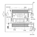
本実施例(第二実施例)におけるプレス成形装置201は、前述した第一実施例におけるプレス成形装置1に対して、主な構成を同じくする一方、プレス成形装置1の第一温度調節機能25および第二温度調節機能35に代えて、第一温度調整機能225および第二温度調節機能235を備えている点で、プレス成形装置1と異なっている。
なお、以下において、第一実施例におけるプレス成形装置1と同じくする構成についての説明は省略し、主に、第一温度調整機能225および第二温度調節機能235の構成について説明する。
The
In addition, below, description about the structure similar to the press molding apparatus 1 in a 1st Example is abbreviate | omitted, and mainly the structure of the 1st
第一温度調節機能225は、第一冷却手段222や第一温度検出手段223などを有して構成される。また、第二温度調節機能235は、第二冷却手段232や第二温度検出手段233などを有して構成される。
なお、これらの第一温度調節機能225および第二温度調節機能235は、互いに同等な構成からなるため、以下においては、第一温度調節機能225についての説明のみ行い、第二温度調節機能235に関する説明を省略する。
The first
Since the first
第一冷却手段222は、パンチホルダー221を介して、パンチ202を所定の温度にまで冷却し、調節(温調)するための手段である。
第一冷却手段222は、例えば、本体部222aや冷却板222bなどからなる冷却ユニットによって構成される。
The first cooling means 222 is a means for cooling the
The 1st cooling means 222 is comprised by the cooling unit which consists of the main-
本体部222aは、冷却水を貯溜するタンクや、該冷却水を本体部222aの外部に導くための配管経路や、該配管経路の中途部に設けられる吐出ポンプなどを有して構成される。また、冷却板222bは、熱伝導率の高いシート状部材や、該シート状部材上にて、蛇行しつつ配設される流通経路などを有して構成される。
The
そして、本体部222aの配管経路と冷却板222bの流通経路とは互いに連通されており、本体部222aより吐出された冷却水は、冷却板222b内を通って、再び本体部222a内に導かれる。また、本体部222aは、電気コードなどを介して、制御装置204と電気的に接続され、冷却板222bは、パンチホルダー221の外周面に沿って配設される。
The piping path of the
このような構成からなる第一冷却手段222においては、本体部222aが制御装置204の制御により作動し、該本体部222aより吐出された冷却水が、冷却板222b内に導かれる。その結果、パンチホルダー221が第一冷却手段222によって冷却され、パンチホルダー221とパンチ202との間の熱伝導により、該パンチ202が冷却される。つまり、第一冷却手段222は、パンチホルダー221を介して、パンチ202を冷却するのである。
なお、第一冷却手段222の構成については、本実施例に示すような冷却ユニットに限定されるものではなく、例えば、空冷式のクーラーなどであってもよい。
In the first cooling means 222 having such a configuration, the
In addition, about the structure of the 1st cooling means 222, it is not limited to a cooling unit as shown in a present Example, For example, an air-cooled cooler etc. may be sufficient.
第一温度検出手段223は、パンチホルダー221を介して、冷却後のパンチ202の温度を測定するための手段である。
第一温度検出手段223は、例えば、既知の接触式温度センサーなどによって構成され、パンチホルダー221の外周面に常に触接するようにして配設される。また、第一温度検出手段223は、電気コードなどを介して、制御装置204と電気的に接続される。
The first temperature detection means 223 is a means for measuring the temperature of the
The first temperature detection means 223 is constituted by, for example, a known contact temperature sensor, and is disposed so as to always come into contact with the outer peripheral surface of the
そして、第一冷却手段222によるパンチ202(より具体的には、パンチホルダー221。以下同じ。)の冷却が開始された後、該パンチ202の温度、即ち熱伝導の影響によってパンチ202と同等になったパンチホルダー221の温度は、第一温度検出手段223によって、ある一定の周期ごとに逐一検出され、該検出値が所定の温度に達すると、第一冷却手段222は、制御装置4により、パンチ202(より具体的には、パンチホルダー221。以下同じ。)の温度が所定温度に保持されるように制御される。
このように、第一温度検出手段223は、パンチホルダー221を介してパンチ202の温度を検出するのである。
After the cooling of the punch 202 (more specifically, the
As described above, the first temperature detecting means 223 detects the temperature of the
なお、第一温度検出手段223の構成については、本実施例に示すような接触式温度センサーに特に限定されるものではなく、例えば、赤外線を利用した非接触式温度センサーなどであってもよい。 The configuration of the first temperature detecting means 223 is not particularly limited to the contact temperature sensor as shown in the present embodiment, and may be, for example, a non-contact temperature sensor using infrared rays. .
このように、本実施例(第二実施例)におけるプレス成形装置201においては、パンチホルダー221およびダイスホルダー231の双方に対して、第一温度調節機能225および第二温度調節機能235が各々設けられることとしているが、本発明に係るプレス成形装置は、これに限定されるものではない。
Thus, in the
即ち、本発明を具現化するプレス成形装置201は、パンチ202とダイス203との温度差を変更し、両者の熱膨張量の差を調節することを特徴とするため、例えば、パンチホルダー221およびダイスホルダー231のうちの何れか一方にのみ、第一温度調節機能225、あるいは第二温度調節機能235が設けられる構成としてもよい。
That is, the
[プレス成形装置201(第二実施例)の成形方法]
次に、第二実施例におけるプレス成形装置201の成形方法について、図2を用いて説明する。
[Molding method of press molding apparatus 201 (second embodiment)]
Next, a forming method of the
第二実施例における成形方法は、前述した第一実施例における成形方法に対して、主な手順を同じくする一方、パンチ202とダイス203との温度差を変更するための手順として、これらパンチ202およびダイス203を個別に冷却することによって行う点について相異する。
なお、以下において、第一実施例における成形方法と、手順を同じくする箇所についての説明は省略し、主に、第一温度調整機能225および第二温度調節機能235による、これらパンチ202およびダイス203の冷却手順について説明する。
The molding method in the second embodiment has the same main procedure as the molding method in the first embodiment described above. On the other hand, as a procedure for changing the temperature difference between the
In the following description, the description of the part having the same procedure as the molding method in the first embodiment is omitted, and the
先ず、パンチ202およびダイス203が「型開き状態」にあるプレス成形装置201において、「運転開始指令」が、入力手段を介して制御装置204に入力される。
すると、制御装置4は、前記「運転開始指令」に基づいて、パンチホルダー221およびダイスホルダー231に対する冷却制御を開始する。
First, in the
Then, the control device 4 starts cooling control for the
即ち、制御装置204は、「運転開始指令」に基づいて、第一冷却手段222の本体部222a、および第二冷却手段232の本体部232aの動作を開始させ、動作を開始した本体部222a・232aは、冷却板222b・232bに冷却水を流入させて、パンチホルダー221およびダイスホルダー231に対する冷却を開始する。
That is, the
一方、制御装置204は、前記「運転開始指令」が入力されると、それ以後前記「測定時間」ごとに、第一温度検出手段223および第二温度検出手段233によるパンチ2およびダイス3の温度の検出値が入力される。
On the other hand, when the “operation start command” is inputted, the
即ち、プレス成形装置1の運転中においては、第一温度検出手段223によって検出されたパンチホルダー221の温度は、パンチ202の「現状温度(t21)」として制御装置204に逐一入力されている。また、第二温度検出手段233によって検出されたダイスホルダー231の温度は、ダイス203の「現状温度(t22)」として制御装置204に逐一入力されている。
そして、制御装置204に入力された「現状温度(t21)」および「現状温度(t22)」は、制御装置4の記憶部に一旦格納される。
That is, during the operation of the press molding apparatus 1, the temperature of the
The “current temperature (t21)” and “current temperature (t22)” input to the
ここで、制御装置204の記憶部には、パンチ202およびダイス203の「設定温度(T21)」および「設定温度(T22)」が予め格納されている。
「設定温度(T21)」および「設定温度(T22)」は、「抜きクリアランス」の大きさが所定の大きさとなる、パンチ202とダイス203との温度差に基づいて、これらパンチ202およびダイス203に対して予め設定された温度である。
Here, the “set temperature (T21)” and “set temperature (T22)” of the
The “set temperature (T21)” and “set temperature (T22)” are based on the temperature difference between the
そして、制御装置4においては、記憶部に一旦格納された「現状温度(t21)」および「現状温度(t22)」と、同じく記憶部に格納される「設定温度(T21)」および「設定温度(T22)」とが、それぞれ比較される。 In the control device 4, “current temperature (t 21)” and “current temperature (t 22)” temporarily stored in the storage unit, and “set temperature (T 21)” and “set temperature” that are also stored in the storage unit. (T22) "is compared with each other.
その結果、例えば、パンチ202において、「現状温度(t21)」が、未だ「設定温度(T1)」をよりも高い場合は(t1>T1)、第一冷却手段222によるパンチホルダー221の冷却が継続される。一方、「現状温度(t21)」が「設定温度(T21)」となるまで低下した場合は、制御装置4は、パンチ202を「設定温度(T21)」に保持するように第一冷却手段222を制御する。また、「現状温度(t21)」が「設定温度(T21)」よりも低くなっていた場合は、第一冷却手段222によるパンチ2の冷却が一旦停止され、パンチ2の温度が「設定温度(T21)」まで低下した後に、パンチ2の温度が「設定温度(T21)」に保持されるように、第一冷却手段222を制御する。
As a result, for example, in the
また、ダイス203において、「現状温度(t22)」が、未だ「設定温度(T22)」よりも高い場合は(t2>T2)、第二冷却手段232によるダイスホルダー231の冷却が継続される。一方、「現状温度(t22)」が「設定温度(T22)」に到達した場合は、制御装置4は、ダイス3を「設定温度(T22)」に保持するように第二冷却手段232を制御する。また、「現状温度(t2)」が「設定温度(T2)」よりも低くなっていた場合は、第二冷却手段232によるダイス3の冷却が一旦停止され、ダイス3の温度が「設定温度(T2)」まで低下した後に、ダイス3の温度が「設定温度(T2)」に保持されるように、第二冷却手段232を制御する。
When the “current temperature (t22)” is still higher than the “set temperature (T22)” in the die 203 (t2> T2), the cooling of the
そして、パンチ202およびダイス203の双方において、「現状温度(t21)(t22)」が、「設定温度(T21)(T22)」に到達すると、プレス成形装置201によるプレス成形が開始する。
Then, when “current temperature (t21) (t22)” reaches “set temperature (T21) (T22)” in both the
即ち、前述した第一実施例における成形方法と同様に、シート状の積層体からなる素材100が、予め軟化された状態でプレス成形装置201に投入される。
投入された素材100は、パンチ202およびダイス203の間において、その積層方向がパンチ202およびダイス203の対向方向と同じ方向となるように配設される。
That is, similar to the molding method in the first embodiment described above, the
The
そして、ダイスホルダー231が上昇し、パンチ202およびダイス203が「型閉じ状態」となることで、素材100にプレス成形が施される。素材100のプレス成形後、ダイスホルダー231が下降し、パンチ202およびダイス203が「型開き状態」となった後、プレス成形された成形品(モータコア)が、ダイス203の凹部203a内より取り出される。
Then, the
その後、プレス成形装置201に対して、再び素材100が投入され、プレス成形が連続的に繰り返され、予め定められた個数分の成形品(モータコア)が成形されると、プレス成形装置201の運転が終了するのである。
Thereafter, the
なお、前述した第一実施例における成形方法と同様に、本実施例のプレス成形装置201における成形方法においては、素材100に対するプレス成形が開始された後も、制御装置204によって、パンチ202およびダイス203の「現状温度(t21)(t22)」が、各々「設定温度(T21)(T22)」に保持されているかどうかを監視し、プレス成形装置201の運転中は、常にパンチ202およびダイス203が「設定温度(T21)(T22)」に保持されるように、温度調節(温調)が行われる。
Similar to the molding method in the first embodiment described above, in the molding method in the
このように、本実施例(第二実施例)におけるプレス成形方法およびプレス成形装置201においては、パンチホルダー221およびダイスホルダー231に対して、第一温度調節機能225および第二温度調節機能235が各々設けられ、これらの第一温度調節機能225および第二温度調節機能235を用いて、パンチホルダー221およびダイスホルダー231を個別に冷却することによって、パンチ202およびダイス203の温度を個別に調節する構成となっている。
Thus, in the press molding method and press
これにより、前述した第一実施例におけるプレス成形方法およびプレス成形装置201と同様に、従来のプレス成形方法およびプレス成形装置に比べて、「抜きクリアランス」の大きさを、極力小さく、且つ常に一定に保つことが可能となり、プレス成形時における「加工歪み」の発生が低減され、成形品であるモータコアの品質向上を図ることができるのである。
As a result, like the press forming method and press forming
また、本実施例(第二実施例)におけるプレス成形方法およびプレス成形装置201においては、パンチ202とダイス203との温度差を変更するための手段として、第一温度調節機能225および第二温度調節機能235を用いて、これらパンチ202およびダイス203を個別に「冷却」することとしている。
よって、前述した第一実施例におけるプレス成形方法およびプレス成形装置1と比べて、パンチ202およびダイス203が高温状態になることもなく、比較的溶解温度の低い部材からなる素材であっても、プレス成形時における「加工歪み」の発生を低減させて、成形品の品質向上を図ることができるのである。
Further, in the press molding method and press
Therefore, compared with the press molding method and press molding apparatus 1 in the first embodiment described above, the
以上、前述した第一実施例および第二実施例に示したように、本発明を具現化するプレス成形方法は、パンチ2(202)と、該パンチ2(202)に対向して配設されるダイス3(203)と、を備え、前記パンチ2(202)において前記ダイス3(203)との対向側には凸部2a(202a)が形成され、前記ダイス3(203)において前記パンチ2(202)との対向側には凹部3a(203a)が形成され、前記パンチ2(202)および前記ダイス3(203)が対向方向に沿って相対的に近接離間するように、前記パンチ2(202)および前記ダイス3(203)の少なくとも一方が移動可能に設けられ、前記パンチ2(202)および前記ダイス3(203)が近接することで、前記凸部2a(202a)が前記凹部3a(203a)に「抜きクリアランス」(隙間。図1における寸法値d。)を有して嵌合されるプレス成形装置1(201)を用いたプレス成形方法であって、前記パンチ2(202)および/または前記ダイス3(203)の温度を変更し、前記パンチ2(202)と前記ダイス3(203)との温度差を調節することで、前記凸部2a(202a)と前記凹部3a(203a)との間の「抜きクリアランス」(隙間)を調節することとしている。
As described above, as shown in the first embodiment and the second embodiment described above, the press molding method embodying the present invention is provided with the punch 2 (202) and facing the punch 2 (202). A
また、前述した第一実施例および第二実施例に示したように、本発明を具現化するプレス成形装置は、パンチ2(202)と、該パンチ2(202)に対向して配設されるダイス3(203)と、を備え、前記パンチ2(202)において前記ダイス3(203)との対向側には凸部2a(202a)が形成され、前記ダイス3(203)において前記パンチ2(202)との対向側には凹部3a(203a)が形成され、前記パンチ2(202)および前記ダイス3(203)が対向方向に沿って相対的に近接離間するように、前記パンチ2(202)および前記ダイス3(203)の少なくとも一方が移動可能に設けられ、前記パンチ2(202)および前記ダイス3(203)が近接することで、前記凸部2a(202a)が前記凹部3a(203a)に「抜きクリアランス」(隙間。図1における寸法値d)を有して嵌合されるプレス成形装置1(201)であって、前記パンチ2(202)および/または前記ダイス3(203)には第一温度調節機能25(225)および/または第二温度調節機能35(235)がそれぞれ備えられ、これらの第一温度調節機能25(225)および/または第二温度調節機能35(235)によって、前記パンチ2(202)および/または前記ダイス3(203)の温度を変更し、前記パンチ2(202)と前記ダイス3(203)との温度差を調節することで、前記凸部2aと前記凹部3a(203a)との間の「抜きクリアランス」(隙間)を調節することとしている。
Further, as shown in the first and second embodiments described above, the press molding apparatus embodying the present invention is provided with a punch 2 (202) and facing the punch 2 (202). A
このような構成を有することで、本実施例(第一実施例および第二実施例)におけるプレス成形方法およびプレス成形装置1(201)によれば、パンチ2(202)に形成された凸部2a(202a)と、ダイス3(203)に形成された凹部3a(203a)とによって、軟化させた素材100を挟持しつつ押圧し、該素材100にプレス成形を施す際、前記凸部2a(202a)の外周面と、前記凹部3a(203a)の内周面との間に形成される隙間(「抜きクリアランス」)の大きさを極力小さくすることが可能となり、成形品の品質向上を図ることができる。
By having such a configuration, according to the press molding method and press molding apparatus 1 (201) in the present embodiment (first embodiment and second embodiment), the convex portion formed on the punch 2 (202). 2a (202a) and the
即ち、本実施例(第一実施例および第二実施例)におけるプレス成形方法およびプレス成形装置1(201)によれば、実際のパンチ2(202)およびダイス3(203)(より具体的には、凸部2a(202a)および凹部3a(203a))の形状や組付け位置を考慮しながら、自由に前記「抜きクリアランス」の大きさを調節して、極力小さな値(およそ数μm)に設定することが可能となる。
また、これら凸部2a(202a)および凹部3a(203a)に発生する摩耗量に基づいて、パンチ2(202)とダイス3(203)との温度差を変更し、熱膨張量の差を調節することができるため、前記「抜きクリアランス」の大きさを常に一定に保つことが可能となる。
従って、「抜きクリアランス」の大きさを、極力小さく、且つ常に一定に保つことが可能となり、長期にわたって、プレス成形時における「加工歪み」の発生を低減して、成形品の品質向上を図り、維持することができるのである。
That is, according to the press molding method and press molding apparatus 1 (201) in the present embodiment (first embodiment and second embodiment), the actual punch 2 (202) and die 3 (203) (more specifically, In consideration of the shape and assembly position of the
Further, the temperature difference between the punch 2 (202) and the die 3 (203) is changed based on the amount of wear generated in the
Therefore, it is possible to keep the size of the “punch clearance” as small as possible and always constant, reduce the occurrence of “working distortion” during press molding over a long period of time, and improve the quality of the molded product. It can be maintained.
また、前述した第一実施例に示したように、本発明を具現化するプレス成形方法において、前記パンチ2と前記ダイス3との温度差の調節は、前記パンチ2および/または前記ダイス3を加熱し、加熱された前記パンチ2および/または前記ダイス3の温度(「現状温度(t1)」および/または「現状温度(t2)」)を、所定の温度(「設定温度(T1)」および/または「設定温度(T2)」)に保持することによって行われることとしている。 Further, as shown in the first embodiment, in the press molding method embodying the present invention, the temperature difference between the punch 2 and the die 3 is adjusted by adjusting the punch 2 and / or the die 3. The temperature of the heated punch 2 and / or the die 3 (“current temperature (t1)” and / or “current temperature (t2)”) is changed to a predetermined temperature (“set temperature (T1)” and / Or “set temperature (T2)”).
また、前述した第一実施例に示したように、本発明を具現化すプレス成形装置1において、前記第一温度調節機能25および/または第二温度調節機能35は、前記パンチ2および/または前記ダイス3を加熱する第一加熱手段22および/または第二加熱手段32と、前記パンチ2および/または前記ダイス3の温度を検出する第一温度検出手段23および/または第二温度検出手段33と、を有して構成されることとしている。
Further, as shown in the first embodiment described above, in the press molding apparatus 1 embodying the present invention, the first
このような構成を有することで、本実施例(第一実施例)におけるプレス成形方法およびプレス成形装置1によれば、例えば、帯状電気ヒーターなどのように、比較的容易な構成からなる機器によって、第一温度調節機能25および第二温度調節機能35を各々実現することが可能であり、他に別途複雑な構成からなる装置類を設ける必要もなく、設備コストが嵩張ることもないのである。
By having such a configuration, according to the press molding method and the press molding apparatus 1 in the present embodiment (first embodiment), for example, by a device having a relatively easy configuration, such as a strip-shaped electric heater. In addition, the first
また、前述した第二実施例に示したように、本発明を具現化すプレス成形方法において、前記パンチ202と前記ダイス203との温度差の調節は、前記パンチ202および/または前記ダイス203を冷却し、冷却された前記パンチ202および/または前記ダイス203の温度(「現状温度(t21)」および/または「現状温度(t22)」)を、所定の温度(「設定温度(T21)」および/または「設定温度(T22)」)に保持することによって行われることとしている。
Further, as shown in the second embodiment, in the press molding method embodying the present invention, the temperature difference between the
また、前述した第二実施例に示したように、本発明を具現化すプレス成形装置201において、前記第一温度調節機能225および/または第二温度調節機能235は、前記パンチ202および/または前記ダイス203を冷却する第一冷却手段222および/または第二冷却手段232と、前記パンチ202および/または前記ダイス203の温度を検出する第一温度検出手段223および/または第二温度検出手段233と、を有して構成されることとしている。
In addition, as shown in the second embodiment described above, in the
このような構成を有することで、本実施例(第二実施例)におけるプレス成形方法およびプレス成形装置201によれば、前述した第一実施例におけるプレス成形方法およびプレス成形装置1と比べて、パンチ202およびダイス203が高温状態になることもなく、比較的溶解温度の低い部材からなる素材であっても、プレス成形時における「加工歪み」の発生を低減させて、成形品の品質向上を図ることができるのである。
By having such a configuration, according to the press molding method and press
1 プレス成形装置
2 パンチ
2a 凸部
3 ダイス
3a 凹部
22 第一加熱手段
23 第一温度検出手段
25 第一温度調節機能
32 第二加熱手段
33 第二温度検出手段
35 第二温度調節機能
201 プレス成形装置
202 パンチ
202a 凸部
203 ダイス
203a 凹部
222 第一冷却手段
223 第一温度検出手段
225 第一温度調節機能
232 第二冷却手段
233 第二温度検出手段
235 第二温度調節機能
DESCRIPTION OF SYMBOLS 1 Press molding apparatus 2
Claims (6)
前記パンチおよび/または前記ダイスの温度を変更し、前記パンチと前記ダイスとの温度差を調節することで、前記凸部と前記凹部との間の隙間を調節する、
ことを特徴とするプレス成形方法。 A punch and a die disposed opposite to the punch, wherein the punch has a convex portion formed on the side facing the die, and the die has a concave portion formed on the side facing the punch. And at least one of the punch and the die is movably provided so that the punch and the die are relatively close to and separated from each other in the opposing direction. A press molding method using a press molding apparatus in which a portion is fitted with a gap in the concave portion,
By changing the temperature of the punch and / or the die and adjusting the temperature difference between the punch and the die, the gap between the convex portion and the concave portion is adjusted,
The press molding method characterized by the above-mentioned.
前記パンチおよび/または前記ダイスを加熱し、加熱された前記パンチおよび/または前記ダイスの温度を、所定の温度に保持することによって行われる、
ことを特徴とする、請求項1に記載のプレス成形方法。 Adjustment of the temperature difference between the punch and the die is
The punch and / or the die is heated, and the temperature of the heated punch and / or the die is maintained at a predetermined temperature.
The press molding method according to claim 1, wherein:
前記パンチおよび/または前記ダイスを冷却し、冷却された前記パンチおよび/または前記ダイスの温度を、所定の温度に保持することによって行われる、
ことを特徴とする、請求項1に記載のプレス成形方法。 Adjustment of the temperature difference between the punch and the die is
The punch and / or the die is cooled, and the temperature of the cooled punch and / or the die is maintained at a predetermined temperature.
The press molding method according to claim 1, wherein:
前記パンチおよび/または前記ダイスには温度調節機能がそれぞれ備えられ、
該温度調節機能によって、前記パンチおよび/または前記ダイスの温度を変更し、前記パンチと前記ダイスとの温度差を調節することで、前記凸部と前記凹部との間の隙間を調節する、
ことを特徴とするプレス成形装置。 A punch and a die disposed opposite to the punch, wherein the punch has a convex portion formed on the side facing the die, and the die has a concave portion formed on the side facing the punch. And at least one of the punch and the die is movably provided so that the punch and the die are relatively close to and separated from each other in the opposing direction. A press molding apparatus in which a portion is fitted with a gap in the recess,
The punch and / or the die are each provided with a temperature control function,
By changing the temperature of the punch and / or the die by the temperature adjustment function, and adjusting the temperature difference between the punch and the die, the gap between the convex portion and the concave portion is adjusted.
A press molding apparatus characterized by that.
前記パンチおよび/または前記ダイスを加熱する加熱手段と、
前記パンチおよび/または前記ダイスの温度を検出する温度検出手段と、
を有して構成される、
ことを特徴とする、請求項4に記載のプレス成形装置。 The temperature control function is
Heating means for heating the punch and / or the die;
Temperature detecting means for detecting the temperature of the punch and / or the die;
Configured with
The press molding apparatus according to claim 4, wherein
前記パンチおよび/または前記ダイスを冷却する冷却手段と、
前記パンチおよび/または前記ダイスの温度を検出する温度検出手段と、
を有して構成される、
ことを特徴とする、請求項4に記載のプレス成形装置。
The temperature control function is
Cooling means for cooling the punch and / or the die;
Temperature detecting means for detecting the temperature of the punch and / or the die;
Configured with
The press molding apparatus according to claim 4, wherein
Priority Applications (1)
| Application Number | Priority Date | Filing Date | Title |
|---|---|---|---|
| JP2011028971A JP2012166235A (en) | 2011-02-14 | 2011-02-14 | Press molding method and press molding device |
Applications Claiming Priority (1)
| Application Number | Priority Date | Filing Date | Title |
|---|---|---|---|
| JP2011028971A JP2012166235A (en) | 2011-02-14 | 2011-02-14 | Press molding method and press molding device |
Publications (1)
| Publication Number | Publication Date |
|---|---|
| JP2012166235A true JP2012166235A (en) | 2012-09-06 |
Family
ID=46970921
Family Applications (1)
| Application Number | Title | Priority Date | Filing Date |
|---|---|---|---|
| JP2011028971A Withdrawn JP2012166235A (en) | 2011-02-14 | 2011-02-14 | Press molding method and press molding device |
Country Status (1)
| Country | Link |
|---|---|
| JP (1) | JP2012166235A (en) |
Cited By (3)
| Publication number | Priority date | Publication date | Assignee | Title |
|---|---|---|---|---|
| JP6110548B1 (en) * | 2016-06-20 | 2017-04-05 | 東芝産業機器システム株式会社 | Iron core manufacturing method, iron core manufacturing equipment |
| JP2018507115A (en) * | 2015-02-06 | 2018-03-15 | ブルックス オートメーション インコーポレイテッド | Tube sealer |
| US11298739B2 (en) | 2018-09-20 | 2022-04-12 | Toyota Jidosha Kabushiki Kaisha | Method for manufacturing iron core |
-
2011
- 2011-02-14 JP JP2011028971A patent/JP2012166235A/en not_active Withdrawn
Cited By (6)
| Publication number | Priority date | Publication date | Assignee | Title |
|---|---|---|---|---|
| JP2018507115A (en) * | 2015-02-06 | 2018-03-15 | ブルックス オートメーション インコーポレイテッド | Tube sealer |
| US10875255B2 (en) | 2015-02-06 | 2020-12-29 | Brooks Automation, Inc. | Tube sealer |
| US11179898B2 (en) | 2015-02-06 | 2021-11-23 | Brooks Automation, Inc. | Tube sealer |
| JP6110548B1 (en) * | 2016-06-20 | 2017-04-05 | 東芝産業機器システム株式会社 | Iron core manufacturing method, iron core manufacturing equipment |
| JP2017225978A (en) * | 2016-06-20 | 2017-12-28 | 東芝産業機器システム株式会社 | Method for manufacturing iron core and device for manufacturing iron core |
| US11298739B2 (en) | 2018-09-20 | 2022-04-12 | Toyota Jidosha Kabushiki Kaisha | Method for manufacturing iron core |
Similar Documents
| Publication | Publication Date | Title |
|---|---|---|
| KR101706100B1 (en) | Tester for obtaining forming limit diagram | |
| JP5011531B2 (en) | Deep drawing machine | |
| JP5934272B2 (en) | Hot press deep drawing method and apparatus | |
| JP5405398B2 (en) | Warm forming mold | |
| JP6667208B2 (en) | Press forming apparatus and press forming method | |
| JPWO2012011224A1 (en) | Steel plate forming method by hot pressing | |
| JP5515774B2 (en) | Hot press molding method and hot press molding apparatus | |
| EP2743062B1 (en) | Fiber reinforced composite panel shaping method | |
| KR101438453B1 (en) | Hot stamping method and mold device for forming and trimming of blank | |
| JP2015142928A (en) | Press device and hot pressing method | |
| JP2012166235A (en) | Press molding method and press molding device | |
| US9815103B2 (en) | Warm working method for stainless steel foil and mold for warm working | |
| JP2011031285A (en) | Heating structure of die | |
| JP2018103266A (en) | Press device | |
| JP6378960B2 (en) | Press machine | |
| US11298739B2 (en) | Method for manufacturing iron core | |
| JP2013094793A (en) | Hot press forming method, formed object by hot press forming, as well as die for hot press forming | |
| JP2007260761A (en) | Hot press forming device | |
| JP5856515B2 (en) | Hot press molding apparatus and hot press molding method | |
| JP5786728B2 (en) | Press forming method and apparatus | |
| KR101553662B1 (en) | Hot plate structure of press molding device and continuous molding method using the same | |
| JP2018083223A (en) | Press device | |
| JP2014079801A (en) | Hot forging device | |
| KR20150051014A (en) | Apparatus for warm press and method having the same | |
| KR101913095B1 (en) | Draw type warm press mold device |
Legal Events
| Date | Code | Title | Description |
|---|---|---|---|
| A300 | Withdrawal of application because of no request for examination |
Free format text: JAPANESE INTERMEDIATE CODE: A300 Effective date: 20140513 |