JP2012165488A - Cooling device for rotary electric machine - Google Patents
Cooling device for rotary electric machine Download PDFInfo
- Publication number
- JP2012165488A JP2012165488A JP2011021774A JP2011021774A JP2012165488A JP 2012165488 A JP2012165488 A JP 2012165488A JP 2011021774 A JP2011021774 A JP 2011021774A JP 2011021774 A JP2011021774 A JP 2011021774A JP 2012165488 A JP2012165488 A JP 2012165488A
- Authority
- JP
- Japan
- Prior art keywords
- rotor
- oil
- cooling device
- microbubble
- electrical machine
- Prior art date
- Legal status (The legal status is an assumption and is not a legal conclusion. Google has not performed a legal analysis and makes no representation as to the accuracy of the status listed.)
- Withdrawn
Links
Images


Abstract
Description
本発明は、回転電機の冷却装置に関する。 The present invention relates to a cooling device for a rotating electrical machine.
従来、自動車等の車両の駆動装置としてモータや発電機などの回転電機を備えたものが知られている。回転電機は、作動に伴って熱を発生する。この発熱は回転電機の運転効率を低下させる虞があるので、作動中に回転電機を冷却する必要がある。 2. Description of the Related Art Conventionally, a drive device for a vehicle such as an automobile is known that includes a rotating electrical machine such as a motor or a generator. The rotating electrical machine generates heat as it operates. Since this heat generation may reduce the operating efficiency of the rotating electrical machine, it is necessary to cool the rotating electrical machine during operation.
例えば、特許文献1には、シャフト内に導入された冷媒を、ロータの回転で発生する遠心力によりステータ側に供給して回転電機を冷却する冷却装置が記載されている。 For example, Patent Document 1 describes a cooling device that cools a rotating electrical machine by supplying a refrigerant introduced into a shaft to a stator side by centrifugal force generated by rotation of a rotor.
しかしながら、特許文献1のように、回転電機内に冷媒を供給する冷却装置では、供給された冷媒がロータとステータとの間に浸入し、この浸入した冷媒の影響でロータが回転すると引き摺りトルクが発生し、この結果、運転効率が低下して燃費を悪化させる虞がある。 However, as in Patent Document 1, in a cooling device that supplies refrigerant into a rotating electrical machine, the supplied refrigerant enters between the rotor and the stator, and drag torque is generated when the rotor rotates due to the influence of the entered refrigerant. As a result, there is a possibility that the driving efficiency is lowered and the fuel consumption is deteriorated.
本発明は、上記の事情に鑑みてなされたものであって、引き摺りトルクの発生を抑制し、燃費悪化を抑制することができる回転電機の冷却装置を提供することを目的とする。 The present invention has been made in view of the above circumstances, and an object of the present invention is to provide a cooling device for a rotating electrical machine that can suppress the generation of drag torque and suppress deterioration in fuel consumption.
本発明は、回転可能に設けられたシャフト内に導入された冷媒を、前記シャフトの周囲に固設されたロータの回転で発生する遠心力により、前記ロータの外周に配置されたステータ側に供給して回転電機を冷却する冷却装置において、前記ロータの外周上に設けられ、前記ロータの回転によりマイクロバブルを発生するマイクロバブル発生部を備えることを特徴とする。 According to the present invention, the refrigerant introduced into the shaft provided rotatably is supplied to the stator side disposed on the outer periphery of the rotor by centrifugal force generated by the rotation of the rotor fixed around the shaft. Then, the cooling device for cooling the rotating electrical machine includes a microbubble generator provided on the outer periphery of the rotor and generating microbubbles by the rotation of the rotor.
前記マイクロバブル発生部は、前記ロータの外周上に形成された凹形状部であることが好ましい。 The microbubble generating part is preferably a concave part formed on the outer periphery of the rotor.
または、前記マイクロバブル発生部は、前記ロータの外周上に形成された凸形状部であることが好ましい。 Or it is preferable that the said microbubble generation | occurrence | production part is a convex-shaped part formed on the outer periphery of the said rotor.
本発明に係る回転電機の冷却装置において、前記シャフト内に導入される冷媒にマイクロバブルを混入するマイクロバブル発生装置を備えることが好ましい。 The cooling device for a rotating electrical machine according to the present invention preferably includes a microbubble generator that mixes microbubbles into the refrigerant introduced into the shaft.
本発明にかかる回転電機の冷却装置は、ロータの外周上に設けられたマイクロバブル発生部においてロータの回転に伴いマイクロバブルを発生させ、このマイクロバブルによりロータ表面に空気膜を形成させる。この結果、引き摺りトルクの発生を抑制し、燃費悪化を抑制することができるというという効果を奏する。 The cooling device for a rotating electrical machine according to the present invention generates microbubbles along with the rotation of a rotor in a microbubble generator provided on the outer periphery of the rotor, and forms an air film on the rotor surface by the microbubbles. As a result, there is an effect that generation of drag torque can be suppressed and fuel consumption deterioration can be suppressed.
以下に、本発明に係る回転電機の冷却装置の実施形態を図面に基づいて詳細に説明する。なお、以下の図面において、同一または相当する部分には同一の参照番号を付し、その説明は繰り返さない。 Hereinafter, embodiments of a cooling apparatus for a rotating electrical machine according to the present invention will be described in detail with reference to the drawings. In the following drawings, the same or corresponding parts are denoted by the same reference numerals, and the description thereof will not be repeated.
〔第一実施形態〕
まず、図1〜6を参照して、本発明の第一実施形態について説明する。図1は、本実施形態に係る回転電機の冷却装置の概略構成を示す断面図である。図中に示す回転電機は、ガソリンエンジンやディーゼルエンジン等の内燃機関と、充放電可能な2次電池(バッテリ)から電力供給されるモータとを動力源とするハイブリッド自動車に搭載されたモータである。そして、回転電機とは、電力が供給されてモータとしての機能と、発電機(ジェネレータ)としての機能との少なくとも一方の機能を有するモータジェネレータを意味する。
[First embodiment]
First, with reference to FIGS. 1-6, 1st embodiment of this invention is described. FIG. 1 is a cross-sectional view illustrating a schematic configuration of a cooling device for a rotating electrical machine according to the present embodiment. The rotating electrical machine shown in the figure is a motor mounted on a hybrid vehicle that uses an internal combustion engine such as a gasoline engine or a diesel engine and a motor powered by a chargeable / dischargeable secondary battery (battery) as a power source. . The rotating electric machine means a motor generator having at least one of a function as a motor and a function as a generator (generator) when electric power is supplied.
図1を参照して、回転電機100は、ロータ10と、ロータ10の外周に配置されたステータ50とを備える。ロータ10は、中心線101に沿って延びるシャフト58に設けられている。ロータ10は、シャフト58の周囲に固設され、シャフト58とともに中心線101を中心に回転する。なお、ロータ10及びステータ50は、シャフト58を回転可能に保持するハウジング(図示せず)の内部に収納されている。
Referring to FIG. 1, rotating
ロータ10は、ロータコア20と、ロータコア20に埋設された永久磁石31とを有する。すなわち、回転電機100は、IPM(Interior Permanent Magnet)モータである。ロータコア20は、中心線101に沿った円筒形状を有する。ロータコア20は、中心線101の軸方向に積層された複数の電磁鋼板21から構成されている。
The
中心線101方向に位置するロータ10の軸方向端面には、エンドプレート29が設けられている。
An
ステータ50は、ステータコア55と、ステータコア55に巻回されたコイル51とを有する。ステータコア55は、中心線101の軸方向に積層された複数の電磁鋼板52から構成されている。なお、ロータコア20およびステータコア55は、電磁鋼板に限定されず、たとえば圧粉磁心から構成されても良い。
The
コイル51は、3相ケーブル60によって制御装置70に電気的に接続されている。3相ケーブル60は、U相ケーブル61、V相ケーブル62およびW相ケーブル63からなる。コイル51は、U相コイル、V相コイルおよびW相コイルからなり、これらの3つのコイルの端子に、それぞれ、U相ケーブル61、V相ケーブル62およびW相ケーブル63が接続されている。
The
制御装置70には、ハイブリッド自動車に搭載されたECU(Electrical Control Unit)80から、回転電機100が出力すべきトルク指令値が送られる。制御装置70は、そのトルク指令値によって指定されたトルクを出力するためのモータ制御電流を生成し、そのモータ制御電流を、3相ケーブル60を介してコイル51に供給する。
A torque command value to be output by the rotating
図2は、図1に示すロータ10の一部を拡大視した拡大断面図である。図2に示すように、回転電機100は、シャフト58に導入される冷却用のオイル(冷媒)Aによって永久磁石31を冷却する磁石冷却通路40を備えている。この磁石冷却通路40は、シャフト58内部に形成された冷媒通路45と、この冷媒通路45に連通し、エンドプレート29に形成された冷媒通路43と、冷媒通路43に連通する排出孔44とを備えている。
FIG. 2 is an enlarged cross-sectional view in which a part of the
冷媒通路45は、中心線101方向に延びる軸方向通路41と、この軸方向通路41に連設され、シャフト58の径方向に向けて延びる径方向通路42とを備えている。
The
冷媒通路43は、径方向通路42に接続され、永久磁石31に向けて延びる流路43aと、この流路43aの外径方向端部に接続され、この径方向端部からロータ10の径方向内方に向けて延びる流路43bとを備えている。
The
流路43aは、エンドプレート29の主表面29a〜29dのうち、ロータ10の軸方向端面10bと対向する主表面29c,29dに形成された溝部と、ロータ10の軸方向端面10a,10bとによって規定されている。流路43aは、永久磁石31の表面のうち、ロータコア20の軸方向に位置する軸方向端面31a,31bを経由している。これにより、耐熱性の低い永久磁石31をオイルによって冷却することができる。
Of the
そして、図2において、流路43bは、流路43aの外径方向端部に接続され、この流路43aの外径方向端部からロータ10の径方向内方に向けて延びる。このように、エンドプレート29内において、冷媒通路43が長尺に形成されることで、オイルとエンドプレート29との接触面積を増大させることができ、エンドプレート29を良好に冷却することができ、エンドプレート29内の発熱による磁石の温度上昇の低減を図ることができる。
In FIG. 2, the
排出孔44は、エンドプレート29の主表面29a,29bに開口している。この排出孔44からオイルは、外部に排出される。
The
次に、本実施形態の冷却装置による回転電機の冷却構造について説明する。中空のシャフト58の内部に形成された冷媒通路45内へ外部から供給されたオイルAは、軸方向通路41の内部を中心線101の方向に沿うように流れる。シャフト58は回転しているので遠心力が発生し、オイルAは軸方向通路41の壁面に沿って流れる。この遠心力の作用によって、径方向通路42に到達したオイルAの一部は径方向通路42へ流入し、シャフト58の径方向外側に向かって、径方向通路42の内部を流れる。
Next, the cooling structure of the rotating electrical machine by the cooling device of this embodiment will be described. Oil A supplied from the outside into the
そして、オイルAは、エンドプレート29内の冷媒通路43へ流入し、冷媒通路43の内部を流通して、ロータ10の軸方向端面10a,10b、永久磁石31の軸方向端面31a,31b、及びエンドプレート29を冷却する。その後に、オイルAは排出孔44へ到り、排出孔44から回転電機の内部空間へと流れ出る。
Then, the oil A flows into the
さらに、オイルAにはロータ10の回転により発生する遠心力が作用しているため、オイルAは、この遠心力により排出孔44からロータ10の外周側(ステータ50側)へ向かって供給され、噴霧されて飛散する。そしてこのように飛散したオイルAは、ステータ50のコイル51の回転半径方向内方側の表面51aに到達して、コイル51を冷却する。このように、シャフト58に導入されたオイルAによって、ロータ10(ロータ10の軸方向端面10a,10b、永久磁石31の軸方向端面31a,31b、及びエンドプレート29)及びステータ50(コイル51)を含む回転電機100が冷却される。
Furthermore, since the centrifugal force generated by the rotation of the
ここで、このような冷却構造において、ロータ10の排出孔44からステータ方向にオイルが噴霧されて飛散する際に、飛散したオイルの一部がロータ10とステータ50とのなす隙間に浸入する場合がある。隙間にオイルが浸入すると、オイルの粘性により引き摺りトルクが発生し、ロータの回転が妨げられ、この結果運転効率の悪化や燃費の悪化を引き起こす虞がある。
Here, in such a cooling structure, when oil is sprayed and scattered from the
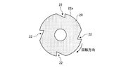
そこで、特に本実施形態では、このような状況を回避すべく、ロータ10の外周上、より詳細にはロータコア20の外周面20a(図3、4参照)にマイクロバブル発生部22が設けられている。マイクロバブル発生部22とは、ロータ10の回転によりロータ10の周囲にマイクロバブルBを発生させるものであり、具体的には、ロータ10(ロータコア20)の外周面20aに形成された複数の凹形状をなす部分である。
Therefore, in particular, in the present embodiment, in order to avoid such a situation, the
図3は、ロータコア20を中心線101の方向からみた図であり、図4は、図3に示すマイクロバブル発生部22の1つを拡大視した図である。図3及び図4に示すように、マイクロバブル発生部22は、ロータコア20の軸線方向視において、それぞれが三角形状の断面形状をなす凹形状部であり、より詳細には、ロータコア20の軸線方向視において、ロータ10(ロータコア20)の回転方向に対する前部22aでは、外周面20aから略直角(または鋭角)に窪み、最下点22bから緩やかに外周面20aへ復帰する断面形状をなしている。
FIG. 3 is a view of the
このようなマイクロバブル発生部22は、ロータ10とステータ50との間にオイルAが浸入すると、ロータ10の回転にともなってマイクロバブル発生部22の前部22aにおいて負圧を発生させる。負圧が発生すると、オイルAに溶解している空気が膨張してマイクロバブルBとして析出される。
When the oil A enters between the
マイクロバブルBが発生すると、ロータ10とステータ50との間にはオイルA及びマイクロバブルBが混在するようになる。ここで、オイルAの密度はマイクロバブルBのものより大きいため、オイルAはマイクロバブルBに比べてより大きな遠心力がかかり、ロータ10の回転に伴ってオイルAはステータ50側へ移動する。一方、マイクロバブルBはロータ側に滞留し、これによりロータ表面(ロータコア20の外周面20a)に空気膜が形成される。
When microbubbles B are generated, oil A and microbubbles B are mixed between the
この結果、ロータ10は、形成された空気膜によってロータ10とステータ50との間に浸入したオイルAと接触しにくくなり、回転時にオイルAの影響を受けにくくなるため、引き摺りトルクが低減する。
As a result, the
このように、本実施形態に係る回転電機の冷却装置によれば、ロータ10の外周上(ロータコア20の外周面20a)にマイクロバブル発生部22を備えるので、ロータ10の回転に応じてロータ10の外周にマイクロバブルBを発生させ、引き摺りトルクの発生を抑制し、燃費悪化を抑制できる。また、発生したマイクロバブルBによって、ロータ10とステータ50との間にオイルがさらに浸入することが抑制される。
As described above, according to the cooling apparatus for a rotating electrical machine according to the present embodiment, the
また、マイクロバブル発生部22は、ロータ10(ロータコア20)の外周上に形成された凹形状部であるため、引き摺りトルクの発生を抑制しつつ、ロータ10及びステータ50間のクリアランスを小さくすることができ、この結果、最大発生トルクが向上する。また、マイクロバブル発生部22は既存のロータ10の電磁鋼板21を切削加工すれば設置することができるので、別途部材を設ける必要がなく、低コスト化を図ることができる。
Moreover, since the
なお、上記実施形態では、マイクロバブル発生部22の凹形状として、ロータコア20の軸線方向視において三角形状の断面形状をなすものを例示したが、負圧を発生させることさえできれば、四角形、多角形、半円など他の断面形状としてもよい。また、オイルの流れ方向に対してロータ10の外周形状を急激に変化するほど負圧が大きくなるので、マイクロバブル発生部22の断面形状は、ロータ10(ロータコア20)の回転方向に対する前部22aにおいて、鋭角または直角に凹むようにとることが好ましい。また、マイクロバブル発生部22の凹形状部の個数は、単数でも複数でもよい。
In the above-described embodiment, the concave shape of the
また、マイクロバブル発生部22の形状は、上記のようにロータ10の回転方向に沿った複数の凹形状の他に、オイルの流れ方向(ロータ10の回転方向)と交差するように(例えばらせん状)にロータコア20の外周面20aに設けられた溝としてもよい。
In addition to the plurality of concave shapes along the rotation direction of the
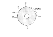
さらに、上記実施形態では、マイクロバブル発生部の形状として凹形状部を例示したが、この代わりに、図5及び図6に示すように、ロータコア20の軸線方向視において、それぞれが三角形状の断面形状をなす複数の凸形状部から成るマイクロバブル発生部23としてもよい。このようなマイクロバブル発生部23は、ロータ10とステータ50との間にオイルが流入すると、図6に示すように、ロータの回転にともなって、ロータ10(ロータコア20)の回転方向に対してマイクロバブル発生部23の後方において負圧を発生させる。したがって、凸形状のマイクロバブル発生部23も、上記の凹形状のマイクロバブル発生部22と同様の作用効果を奏することができる。
Furthermore, in the said embodiment, although the concave shape part was illustrated as a shape of a microbubble generation | occurrence | production part, as shown in FIG.5 and FIG.6, in axial direction view of the
なお、マイクロバブル発生部23の凸形状は、凹形状と同様に、負圧を発生させることさえできれば、図5,6に示した、ロータコア20の軸線方向視において三角形状の断面形状をなすもの以外にも、四角形、多角形、半円など他の断面形状としてもよい。また、オイルの流れ方向に対してロータ外周形状を急激に変化させるほど負圧が大きくなるので、マイクロバブル発生部23の凸形状は、図5,6に示すように、ロータ10(ロータコア20)の回転方向に対し後端23aにおいて、略直角方向にロータ10の外径まで戻るようにとることが好ましい。また、マイクロバブル発生部23の凸形状部の個数は、単数でも複数でもよい。
Note that the convex shape of the
また、マイクロバブル発生部23の形状は、ロータ10の回転方向に沿った複数の凸形状の他に、オイルの流れ方向(ロータの回転方向)と交差するように(例えばらせん状)にロータ外周面に設けられた線条部材としてもよい。
In addition to the plurality of convex shapes along the rotation direction of the
マイクロバブル発生部22の凹形状と、マイクロバブル発生部23の凸形状とを組み合わせ、両方をロータ10の外周上に設けることも可能である。
It is also possible to combine the concave shape of the
〔第二実施形態〕
次に、図7を参照して、本発明の第二実施形態について説明する。本実施形態は、シャフト58へオイルAが導入される前に、冷却用のオイルAにマイクロバブルBを混入するマイクロバブル発生装置90を備える点において、上述の第一実施形態と異なるものである。
[Second Embodiment]
Next, a second embodiment of the present invention will be described with reference to FIG. The present embodiment is different from the first embodiment described above in that it includes a
マイクロバブル発生装置90は、旋回流方式、加圧溶解式、微細孔式などの方式を用いて、オイル供給源(図示せず)からシャフト58へ導入されるオイルAに空気を混入して溶解させ、マイクロバブルBを混入する。
The
このようなマイクロバブル発生装置90によりマイクロバブルBを混入されたオイルが回転電機100内に導入されると、マイクロバブルBが混入されたオイルAがロータ10の外周(ロータ10とステータ50とのなす間隙)に吸い込まれ、さらに、オイルAに溶解している空気がマイクロバブル発生部22,23によりマイクロバブルBとして析出されるので、ロータ10とステータ50との間により一層多くのマイクロバブルBを滞留させることができ、ロータ表面(ロータコア20の外周面20a)により厚い空気膜を形成することができ、この結果、ロータ10とステータ50との間の引き摺りトルクをより一層低減させることができる。
When the oil mixed with the microbubbles B is introduced into the rotating
また、導入されたオイルAには、マイクロバブル発生装置90により、空気が溶解度近傍まで溶け込まれている。このため、小さな負圧(低回転時)でもマイクロバブルBが析出でき、ロータ10とステータ50との間の引き摺りトルクをより一層低減させることができる。
Further, air is dissolved in the introduced oil A to the vicinity of the solubility by the
また、マイクロバブル発生装置90によりオイルAにマイクロバブルBが混入されるため、マイクロバブルBの混入率に応じてオイルAの見かけ密度が低減する。オイルAの密度が低減すると、エンドプレート29側面でのオイル攪拌抵抗が低下するため、オイル攪拌損失が低減する。また、オイルAの密度が低減すると、オイルAの流速が増加する。ここで、熱伝達率は流速と比例関係にあるので、オイルAの流速が増加すれば、熱伝達率も向上する。これにより、ロータ10の冷媒通路43内を通るオイルAによる熱吸収が促進されるので、ロータ10の冷却性が向上する。
In addition, since the microbubbles B are mixed into the oil A by the
以上、本発明について好適な実施形態を示して説明したが、本発明はこれらの実施形態により限定されるものではない。例えば、上記実施形態では、回転電機100を冷却するための冷媒としてオイルAを例示したが、冷却効果のある他のものを使用してもよい。また、ロータ10のエンドプレート29に形成された冷媒通路43の構成や、冷媒通路43に連通する排出孔44の設置位置などは、上記実施形態に例示したものと別の構成や位置としてもよい。
As mentioned above, although preferred embodiment was shown and demonstrated about this invention, this invention is not limited by these embodiment. For example, in the above-described embodiment, the oil A is exemplified as the refrigerant for cooling the rotating
10…ロータ、22,23…マイクロバブル発生部、50…ステータ、58…シャフト、90…マイクロバブル発生装置、100…回転電機、A…冷却用オイル(冷媒)、B…マイクロバブル。
DESCRIPTION OF
Claims (4)
前記ロータの外周上に設けられ、前記ロータの回転によりマイクロバブルを発生するマイクロバブル発生部を備えることを特徴とする回転電機の冷却装置。 The refrigerant introduced into the rotatable shaft is supplied to the stator side disposed on the outer periphery of the rotor by a centrifugal force generated by the rotation of the rotor fixed around the shaft. In the cooling device for cooling
A cooling device for a rotating electrical machine, comprising a microbubble generator provided on an outer periphery of the rotor and generating microbubbles by rotation of the rotor.
Priority Applications (1)
| Application Number | Priority Date | Filing Date | Title |
|---|---|---|---|
| JP2011021774A JP2012165488A (en) | 2011-02-03 | 2011-02-03 | Cooling device for rotary electric machine |
Applications Claiming Priority (1)
| Application Number | Priority Date | Filing Date | Title |
|---|---|---|---|
| JP2011021774A JP2012165488A (en) | 2011-02-03 | 2011-02-03 | Cooling device for rotary electric machine |
Publications (1)
| Publication Number | Publication Date |
|---|---|
| JP2012165488A true JP2012165488A (en) | 2012-08-30 |
Family
ID=46844316
Family Applications (1)
| Application Number | Title | Priority Date | Filing Date |
|---|---|---|---|
| JP2011021774A Withdrawn JP2012165488A (en) | 2011-02-03 | 2011-02-03 | Cooling device for rotary electric machine |
Country Status (1)
| Country | Link |
|---|---|
| JP (1) | JP2012165488A (en) |
Cited By (2)
| Publication number | Priority date | Publication date | Assignee | Title |
|---|---|---|---|---|
| JP2019103352A (en) * | 2017-12-07 | 2019-06-24 | アイシン精機株式会社 | Vehicle motor cooling structure |
| US20190238030A1 (en) * | 2018-01-30 | 2019-08-01 | Honda Motor Co., Ltd. | Stator-cooling structure and rotary electric machine |
-
2011
- 2011-02-03 JP JP2011021774A patent/JP2012165488A/en not_active Withdrawn
Cited By (3)
| Publication number | Priority date | Publication date | Assignee | Title |
|---|---|---|---|---|
| JP2019103352A (en) * | 2017-12-07 | 2019-06-24 | アイシン精機株式会社 | Vehicle motor cooling structure |
| US20190238030A1 (en) * | 2018-01-30 | 2019-08-01 | Honda Motor Co., Ltd. | Stator-cooling structure and rotary electric machine |
| CN110098696A (en) * | 2018-01-30 | 2019-08-06 | 本田技研工业株式会社 | Cooling structure of stator and rotating electric machine |
Similar Documents
| Publication | Publication Date | Title |
|---|---|---|
| JP5202143B2 (en) | Outer rotor type vehicle generator | |
| US8242646B2 (en) | Rotating electric machine and drive device | |
| US9729027B2 (en) | Cooling structure of rotary electric machine | |
| JP4949983B2 (en) | Rotating electric machine | |
| JP5751065B2 (en) | End plate of rotor and rotating electric machine | |
| JP5772544B2 (en) | Cooling structure of rotating electric machine | |
| US9030062B2 (en) | Cooling structure of rotating electric machine | |
| JP2009027837A (en) | Rotary electric machine | |
| JP2012223075A (en) | Cooling structure of rotary electric machine | |
| JP2009118712A (en) | Dynamo-electric machine | |
| JP2009195082A (en) | Cooling structure of stator | |
| JP5417960B2 (en) | Rotating electric machine | |
| JP2009017700A (en) | Cooling device of rotating electric machine | |
| JP2011217438A (en) | Cooling system for rotating electric machine | |
| JP2011114987A (en) | Cooling structure of electric motor | |
| JP2005253263A (en) | Cooling device for motor | |
| JP2012165488A (en) | Cooling device for rotary electric machine | |
| JP2005073351A (en) | Cooling structure of rotating electric machine | |
| JP2007336677A (en) | Electric rotating machine and vehicle | |
| JP5630418B2 (en) | Cooling device for rotating electrical machine for vehicle | |
| JP2011142787A (en) | Cooling structure for electric motor | |
| JP2011114986A (en) | Cooling structure of electric motor | |
| JP2019170030A (en) | Motor cooling system | |
| JP2010273504A (en) | Rotor, rotary electric machine, and vehicle | |
| KR20140004313A (en) | Cooling structure for motor rotator |
Legal Events
| Date | Code | Title | Description |
|---|---|---|---|
| A300 | Withdrawal of application because of no request for examination |
Free format text: JAPANESE INTERMEDIATE CODE: A300 Effective date: 20140513 |