JP2012165468A - Single user detection - Google Patents
Single user detection Download PDFInfo
- Publication number
- JP2012165468A JP2012165468A JP2012118591A JP2012118591A JP2012165468A JP 2012165468 A JP2012165468 A JP 2012165468A JP 2012118591 A JP2012118591 A JP 2012118591A JP 2012118591 A JP2012118591 A JP 2012118591A JP 2012165468 A JP2012165468 A JP 2012165468A
- Authority
- JP
- Japan
- Prior art keywords
- data vector
- channel response
- spread data
- calculating
- matrix
- Prior art date
- Legal status (The legal status is an assumption and is not a legal conclusion. Google has not performed a legal analysis and makes no representation as to the accuracy of the status listed.)
- Pending
Links
- 238000001514 detection method Methods 0.000 title description 19
- 239000013598 vector Substances 0.000 claims abstract description 92
- 238000004891 communication Methods 0.000 claims abstract description 57
- 238000001228 spectrum Methods 0.000 claims abstract description 9
- 239000011159 matrix material Substances 0.000 claims description 82
- 238000000034 method Methods 0.000 claims description 57
- 238000004364 calculation method Methods 0.000 claims description 43
- 238000005070 sampling Methods 0.000 claims description 33
- 238000009792 diffusion process Methods 0.000 claims description 14
- 239000002131 composite material Substances 0.000 claims description 12
- 238000012545 processing Methods 0.000 claims description 2
- 230000002194 synthesizing effect Effects 0.000 claims 1
- 238000006467 substitution reaction Methods 0.000 description 15
- 230000005540 biological transmission Effects 0.000 description 14
- 230000014509 gene expression Effects 0.000 description 11
- 238000000354 decomposition reaction Methods 0.000 description 6
- 238000010586 diagram Methods 0.000 description 6
- 238000013459 approach Methods 0.000 description 4
- 125000004122 cyclic group Chemical group 0.000 description 2
- 230000000694 effects Effects 0.000 description 2
- 238000012549 training Methods 0.000 description 2
- 238000011161 development Methods 0.000 description 1
- 238000003780 insertion Methods 0.000 description 1
- 230000037431 insertion Effects 0.000 description 1
- 230000010363 phase shift Effects 0.000 description 1
- 230000008707 rearrangement Effects 0.000 description 1
- 230000003252 repetitive effect Effects 0.000 description 1
- 238000001308 synthesis method Methods 0.000 description 1
Images


Classifications
-
- H—ELECTRICITY
- H04—ELECTRIC COMMUNICATION TECHNIQUE
- H04B—TRANSMISSION
- H04B1/00—Details of transmission systems, not covered by a single one of groups H04B3/00 - H04B13/00; Details of transmission systems not characterised by the medium used for transmission
- H04B1/69—Spread spectrum techniques
- H04B1/707—Spread spectrum techniques using direct sequence modulation
- H04B1/7097—Interference-related aspects
- H04B1/7103—Interference-related aspects the interference being multiple access interference
- H04B1/7105—Joint detection techniques, e.g. linear detectors
-
- H—ELECTRICITY
- H04—ELECTRIC COMMUNICATION TECHNIQUE
- H04B—TRANSMISSION
- H04B1/00—Details of transmission systems, not covered by a single one of groups H04B3/00 - H04B13/00; Details of transmission systems not characterised by the medium used for transmission
- H04B1/69—Spread spectrum techniques
- H04B1/707—Spread spectrum techniques using direct sequence modulation
- H04B1/7073—Synchronisation aspects
- H04B1/7075—Synchronisation aspects with code phase acquisition
- H04B1/7077—Multi-step acquisition, e.g. multi-dwell, coarse-fine or validation
-
- H—ELECTRICITY
- H04—ELECTRIC COMMUNICATION TECHNIQUE
- H04B—TRANSMISSION
- H04B1/00—Details of transmission systems, not covered by a single one of groups H04B3/00 - H04B13/00; Details of transmission systems not characterised by the medium used for transmission
- H04B1/69—Spread spectrum techniques
- H04B1/707—Spread spectrum techniques using direct sequence modulation
- H04B1/7097—Interference-related aspects
- H04B1/7103—Interference-related aspects the interference being multiple access interference
- H04B1/7105—Joint detection techniques, e.g. linear detectors
- H04B1/71052—Joint detection techniques, e.g. linear detectors using decorrelation matrix
-
- H—ELECTRICITY
- H04—ELECTRIC COMMUNICATION TECHNIQUE
- H04B—TRANSMISSION
- H04B2201/00—Indexing scheme relating to details of transmission systems not covered by a single group of H04B3/00 - H04B13/00
- H04B2201/69—Orthogonal indexing scheme relating to spread spectrum techniques in general
- H04B2201/707—Orthogonal indexing scheme relating to spread spectrum techniques in general relating to direct sequence modulation
- H04B2201/70707—Efficiency-related aspects
-
- H—ELECTRICITY
- H04—ELECTRIC COMMUNICATION TECHNIQUE
- H04L—TRANSMISSION OF DIGITAL INFORMATION, e.g. TELEGRAPHIC COMMUNICATION
- H04L25/00—Baseband systems
- H04L25/02—Details ; arrangements for supplying electrical power along data transmission lines
- H04L25/0202—Channel estimation
- H04L25/0212—Channel estimation of impulse response
Landscapes
- Engineering & Computer Science (AREA)
- Computer Networks & Wireless Communication (AREA)
- Signal Processing (AREA)
- Physics & Mathematics (AREA)
- Mathematical Physics (AREA)
- Mobile Radio Communication Systems (AREA)
- Cable Transmission Systems, Equalization Of Radio And Reduction Of Echo (AREA)
- Monitoring And Testing Of Transmission In General (AREA)
Abstract
Description
この発明は概括的には無線通信システムに関する。さらに詳細にいうと、この発明は無線通信システムにおけるデータ検出に関する。 The present invention generally relates to wireless communication systems. More particularly, the present invention relates to data detection in a wireless communication system.
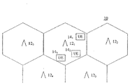
図1は無線通信システム10を示す。無線通信システム10はユーザ装置(UEs)141〜143(14)と通信する基地局121〜125(12)を有する。各基地局には対応する稼働範囲があり、その範囲内で基地局はユーザ装置UEs14と通信する。
FIG. 1 shows a
幾つかの通信システム、例えば符号分割多元接続(CDMA)方式や符号分割多元接続を用いる時分割複信(TDD/CDMA)方式の通信システムでは、多重通信が同一の周波数スペクトラムでなされる。これらの多重通信信号はチャンネル毎に互いに異なる符号を用いることで区別されている。更に効率的に無線周波数スペクトラムを使用するため、TDD/CDMA通信システムでは、通信用に複数の時間スロットに分割された繰返しフレームを使用する。このようなシステムで送られる通信信号では、それぞれが一つの或いは複数の対応する符号とそれに割当てられた時間スロットを有する。一つの時間スロットでの一つの符号使用は資源ユニットと呼ばれる。 In some communication systems, for example, time division duplex (TDD / CDMA) communication systems using code division multiple access (CDMA) or code division multiple access, multiplex communication is performed with the same frequency spectrum. These multiplex communication signals are distinguished by using different codes for each channel. In order to use the radio frequency spectrum more efficiently, the TDD / CDMA communication system uses repetitive frames divided into a plurality of time slots for communication. Each communication signal sent in such a system has one or more corresponding codes and a time slot assigned to it. One code use in one time slot is called a resource unit.
多重通信は同一の無線周波数スペクトラムで同時になされることから、このような通信システムにおける受信機は多数の通信信号を相互に区別する必要がある。このような信号の検出のための一つの手法は多数ユーザ検出法である。多数ユーザ検出法では、全てのユーザ、すなわちユーザ装置UEs14と対応する信号を同時に検出する。多数ユーザ検出を実行する手法は、コレスキー(Cholesky)分解或いは近似コレスキー分解を用いる同時検出を基にするブロック線形等化(BLE-JD)を含む。これらの検出手段は高度の複雑さを伴っている。この複雑さは電力消費を増加させ、ひいてはユーザ装置UEs14の電池寿命の低下をもたらす。そこで、受信データを検出する代替手段の開発が求められている。 Since multiplex communication is performed simultaneously in the same radio frequency spectrum, a receiver in such a communication system needs to distinguish a large number of communication signals from each other. One technique for detecting such signals is the multi-user detection method. In the multi-user detection method, signals corresponding to all users, that is, user apparatuses UEs 14 are detected simultaneously. Techniques for performing multi-user detection include block linear equalization (BLE-JD) based on simultaneous detection using Cholesky decomposition or approximate Cholesky decomposition. These detection means are associated with a high degree of complexity. This complexity increases the power consumption and thus reduces the battery life of the user equipment UEs14. Therefore, development of alternative means for detecting received data is required.
符号分割多元接続通信システムにおいては、送信側は複数のデータ信号を共用周波数スペクトラム経由で送信する。送信されるデータ信号の各々は同様のチャネル応答を受ける。受信側では、それら送信されてきたデータ信号の合成信号が受信される。その合成信号をチップ速度のある倍数の速度でサンプリングする。これにより、受信合成信号に対する共通のチャネル応答を推算する。次に、拡散データベクトルの第1の要素を、上記合成信号のサンプル値とチャネル応答推算値とを使用して算定する。第1のベクトル要素の算定からの係数を用いて、拡散データベクトルの残りのベクトル要素も算定する。データ信号のデータを、算定ずみの拡散データベクトル要素を用いて算定する。 In a code division multiple access communication system, the transmission side transmits a plurality of data signals via a shared frequency spectrum. Each transmitted data signal undergoes a similar channel response. On the receiving side, a composite signal of the transmitted data signals is received. The synthesized signal is sampled at a multiple of the chip speed. Thereby, a common channel response to the received composite signal is estimated. Next, the first element of the spread data vector is calculated using the sample value of the composite signal and the estimated channel response value. The remaining vector elements of the diffusion data vector are also calculated using the coefficients from the calculation of the first vector element. Data of the data signal is calculated using the calculated diffusion data vector element.
CDMA方式と共用周波数スペクトラムによる多重通信の受信装置を単純化し、受信装置の小型化および消費電力の低減を可能にする。 This simplifies the CDMA communication receiver using the CDMA system and the shared frequency spectrum, and enables downsizing the receiver and reducing power consumption.
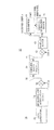
図2にはTDD/CDMA通信システムにおける送信機26と単一ユーザ検出(SUD)手法を用いた受信機28とを単純化した形で示す。単一ユーザ検出手法は他の通信システム、周波数分割複信(FDD)CDMA方式などの通信システムにも適用できる。通常の通信システムにおいては、送信機26は各ユーザ装置UE14内にあり、多重通信を行う多重伝送回路26は各基地局12内にある。SUD受信機28は基地局12、複数のUE14、またはこれらの両者に配置できる。通常、SUD手法はある特定の送信機からの単一符号或いは多符号伝送時におけるデータを検出するのに用いられる。全ての伝送信号が同一の送信機から送られる場合、個々のチャネル符号信号の各々は、多符号伝送では同一のチャネルインパルス応答を受ける。SUD手法は特にダウンリンク、すなわち全ての送信信号が一つの基地局の一つのアンテナ或いはアンテナアレイから輻射されるダウンリンクに有用である。この手法は、単一ユーザが単一符号伝送または多符号伝送で一つのスロットを占有するアップリンクにも有用である。
FIG. 2 shows in simplified form a
送信機26は無線伝送チャネル30経由でデータを送る。受信機26内のデータ発生器32は、受信機28に送信すべきデータを生ずる。変調/拡散系列挿入装置34はデータをスペクトラム拡散し、この拡散ずみ基準データを適切な割当て時間スロット内でミドアンブルトレーニング系列およびデータ拡散用の符号と時分割多重化し、一つの或いは複数の通信信号バーストを発生させる。
The
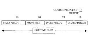
通常の通信信号バースト16は図3に示すとおり、一つのミドアンブル20、一つのガード期間18および二つのデータ領域22,24から成る。ミドアンブル20は二つのデータ領域を分離し、ガード期間18は、互いに異なる送信機26からのバーストの到着時間の差を許容するように通信信号バーストを分離している。二つのデータ領域22、24は通信信号バーストデータを含む。
As shown in FIG. 3, the normal
これらの通信信号バーストで変調器36において無線周波数(RF)を変調する。RF信号はアンテナ38により輻射され、無線伝送チャネル30経由で受信機28のアンテナに達する。この通信信号送信に用いられる変調方式は、直角位相偏位変調(QPSK)やM次直角位相変調(QAM)など当業者に周知の方式のどれであっても差し支えない。
The
受信機28のアンテナ40は種々のRF信号を受信する。受信されたRF信号を復調器42で復調してベースバンド信号を再生する。このベースバンド信号を、単一型または複合型のA−D変換器などのサンプリング装置43によって、送信バースト信号のチップ速度で、あるいはそのチップ速度のある倍数の速さでサンプリングする。サンプリングされた出力を、チャネル推算装置44やSUD装置46などの装置により、受信信号バーストに割当てられたその時間スロット内に適切な符号で処理される。チャネル推算装置44は、ベースバンドサンプルの中のミドアンブルトレーニング系列コンポーネントを用い、チャネルインパルス応答などのチャネル情報を提供する。このチャネルインパルス応答は行列Hとして表わされる。このチャネル情報はSUD装置46で用いられ、それにより、ソフトシンボル受信通信バーストの中の送信されてきたデータが推算される。
The
SUD装置46は、チャネル推算装置44からのチャネル情報および送信機26の用いた既知の拡散符号を使用して、所望の受信した通信バーストのデータを推算する。ここで、SUDは、第三世代パートナシッププロジェクト(3GPP)のユニバーサル地上無線接続(UTRA)TDDシステムを背景の通信システムとして説明するが、このSUDは他のシステムにも適用できる。そのシステムとは、直接拡散方式の広帯域CDMA(W-CDMA)システム、すなわちアップリンク信号およびダウンリンク伝送信号を互いに別々の時間スロットに制限した広帯域CDMA(W-CDMA)である。
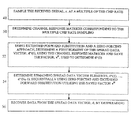
受信機28はそのアンテナ40を用いて同時到達の合計でK個のバースト信号を受信する(48)。これらK個のバースト信号を一つの観察間隔内で互いに重畳させる。3GPP UTRA TDDシステムについては、時間スロットの各データ領域が一つの観察間隔に対応する。
The SUD
The
一つの観察間隔に対し、データ検出課題は式1により表わされる。
For one observation interval, the data detection task is represented by

ここで、rは受信したサンプル値で、Hはチャネル応答行列、dは拡散データベクトルである。拡散データ行列は、各チャネルで伝送されてきたデータとそのチャネルの拡散符号とを含んでいる。 Here, r is a received sample value, H is a channel response matrix, and d is a spread data vector. The spread data matrix includes data transmitted through each channel and the spread code of that channel.
受信信号をオーバーサンプリングした場合は、各送信チップの複数サンプル値を生じ、結果として受信ベクトルr1、…、rNを生ずる(48)。同様に、チャネル推算装置44は、受信ベクトルr1、…、rNに対応するチャネル応答H1、…、HNを算定する(50)。チップ速度の2倍でのサンプリングでは、式1は式2に書き替えられる。
If the received signal is oversampled, a plurality of sample values for each transmission chip are generated, resulting in reception vectors r 1 ,..., R N (48). Similarly, the channel estimation device 44, the received vector r 1, ..., the channel response H 1 corresponding to r N, ..., to calculate the H N (50). For sampling at twice the chip speed,
ここで、r1は偶数番目のサンプル(チップ速度でのサンプリングに対応)で、r2は奇数
番目のサンプル(r1サンプルからチップ間隔の二分の一離れた所でのサンプリングに対応)である。H1は奇数番目のサンプルに対するチャネル応答で、H2は偶数番目に対するその応答である。
Here, r 1 is an even-numbered sample (corresponding to sampling at the chip speed), and r 2 is an odd-numbered sample (corresponding to sampling at a half distance of the chip interval from r 1 sample). . H 1 is the channel response for odd-numbered samples and H 2 is the response for even-numbered samples.
式1は、チップ速度のN倍の速度でのサンプリングでは、式3となる。
ここで、r1、r2,…、rNは、チップ速度のそれぞれの倍数でのサンプルである。各サンプルはチップ間隔のN分の1だけずれている。H1、H2、…、HNは対応するチャネル応答である。以下の説明はチップ速度の2倍の速度でのサンプリングを実行する受信機に絞るが、同様な手法はチップ速度の任意の倍数でのサンプリングに対しても適用できる。 Here, r 1 , r 2 ,..., R N are samples at respective multiples of the chip speed. Each sample is offset by 1 / N of the chip spacing. H 1 , H 2 ,..., H N are the corresponding channel responses. The following description focuses on a receiver that performs sampling at twice the chip rate, but a similar approach can be applied to sampling at any multiple of the chip rate.
チップ速度の2倍の速度でのサンプリングについて、チャネル応答行列H1およびH2の大きさは( Ns+W−1)×Nsとなる。ここで、Nsは観察期間内に送信される拡散チップの数であり、Wはチャネルインパルス応答の長さであり、例えば長さ57チップと表わす。
受信信号はNs個の拡散チップを有するので、r1及びr2の長さはNsである。式2は式4のように書き替えられる。
For sampling at twice the chip rate, the magnitudes of the channel response matrices H 1 and H 2 are (Ns + W−1) × Ns. Here, Ns is the number of spreading chips transmitted within the observation period, and W is the length of the channel impulse response, for example, 57 chips in length.
Since the received signal has the Ns diffusion tip, the length of r 1 and r 2 are Ns.
r1(i)、r2(i)、h1(i)及びh2(i)は、それぞれ対応するベクトル行列r1、r2、H1及び
H2のi番目の要素である。
拡散データベクトルを算定する手法の一つは、拡張前進代入手法であり、その手法を図4を参照して説明する。拡張前進代入のために、受信したデータベクトルを再配列し、各偶数番目のサンプルの次にそれに対応する奇数番目のサンプルを伴うようにする。同様の再配列を式5aに示すとおりチャネル応答行列についても行う。
r 1 (i), r 2 (i), h 1 (i) and h 2 (i) are the i-th elements of the corresponding vector matrices r 1 , r 2 , H 1 and H 2 , respectively.
One of the methods for calculating the spread data vector is an extended forward substitution method, which will be described with reference to FIG. For extended forward substitution, the received data vectors are rearranged so that each even-numbered sample is followed by its corresponding odd-numbered sample. A similar rearrangement is performed for the channel response matrix as shown in Equation 5a.
チップ速度のN倍の速度でのサンプリングについては,式5bが配列となる。 For sampling at N times the chip speed, Equation 5b is an array.
ここで、d(i)は拡散ベクトルdのi番目の要素である。拡散データベクトルの長さはNsである。拡張前進代入手法を用いると、d(0)、d^(0)を算定するためのゼロ強制解が式6aおよび式7aにより表わされる(52)。式6aは Here, d (i) is the i-th element of the diffusion vector d. The length of the spread data vector is Ns. When the extended forward substitution method is used, the zero compulsory solution for calculating d (0) and d ^ (0) is expressed by Equation 6a and Equation 7a (52). Equation 6a is
d(0)についての一般式である。また、式7aはd^(0)についての零強制解である。 This is a general formula for d (0). Equation 7a is a zero compulsory solution for d ^ (0).
同様にして、チップ速度のN倍の速度については、式6b及び式7bを用いる。 Similarly, Expressions 6b and 7b are used for a speed N times the chip speed.
式7a及び式7bを解く際に、後での使用のため、図示のとおりvHを算定するが、式7aについてのvHは式8により算定し、蓄積する(52)。
When solving equation 7a and Formula 7b, for later use, but to calculate the following v H shown, v H for formula 7a are determined using
d^(0)は式9によりvHを用いて算定される。 d ^ (0) is determined using v H by Equation 9.
チップ速度のN倍については、式10(b)を用いる。 For N times the chip speed, Equation 10 (b) is used.
拡散データベクトルの算定のあと、それぞれの通信信号バーストデータを、例えば拡散データベクトルとそれぞれのバースト符号との混合などにより逆拡散する(56)。 After the calculation of the spread data vector, each communication signal burst data is despread by mixing the spread data vector and each burst code, for example (56).
拡張前進代入手法を用いる際の複雑度を、逆拡散の過程を除き、表1に要約する。 The complexity of using the extended forward substitution method is summarized in Table 1, excluding the despreading process.
表1
・ vH の計算 … 4回の乗算と1回の逆数演算
・d^(0)の計算 … 2回の乗算
・d^(1)の計算 … 4回の乗算
・d^(W−1)までの各々の計算 … 2回の乗算
・d^(w)からd^(Ns−1)まで各d^(i)を計算 … (2W+2)回の乗算
・全乗算回数 … 2Ns+(W−1)・W+2W..(Ns−W+1)
・全計算回数 … 2Ns+(W−1)・W+2W..(Ns−W+1)+5
TDDバースト2型についてはNsは1104で、Wは57であるから、毎秒200回、拡張前進代入を用いてdを解くには、チップ速度の2倍でのサンプリングの場合で毎秒99.9016百万回の実演算(MROPS)、チップ速度でのサンプリングに対しては44.95MROPS回の実演算を必要とする。
Table 1
・ Calculation of v H ... 4 multiplications and 1 reciprocal calculation ・ Calculation of d ^ (0) ... 2 multiplications
・ Calculation of d ^ (1) ... 4 multiplications
・ Each calculation up to d ^ (W−1)… 2 multiplications ・ Calculate each d ^ (i) from d ^ (w) to d ^ (Ns−1)… (2W + 2) multiplications ・ All Number of multiplications: 2Ns + (W-1) / W + 2W .. (Ns-W + 1)
・ Total number of calculations: 2Ns + (W-1) ・ W + 2W .. (Ns−W + 1) +5
For TDD burst
データを推算するもう一つの手法はコレスキー法を近似的に帯状化する方法で、これは図5で説明する。相互相関行列Rは正方形(Ns×Ns)になるように算定され、式11により帯状化される(58)。 Another method for estimating the data is a method of approximately banding the Cholesky method, which will be described with reference to FIG. The cross-correlation matrix R is calculated to be a square (Ns × Ns), and is formed into a band according to Equation 11 (58).
ここで(・)Hはエルミート関数を示す。Hは2(Ns+W−1)×Nsの大きさである。式11は、チップ速度の2倍の速度でサンプリングする場合は式12(a)に書き替えられる。 Where (·) H denotes a Hermitian function. H is 2 (Ns + W-1) × Ns. Equation 11 is rewritten as Equation 12 (a) when sampling at twice the chip speed.
チップ速度のN倍の速度でのサンプリングについては、式12(b)を用いる。 For sampling at a speed N times the chip speed, Expression 12 (b) is used.
式12aまたは式12bを用いて得られるRは、大きさNs×Ns型の正方行列で、かつ帯状に区分けされ、チップ速度の2倍の速度でのサンプリングについては、式13に示すように、W=3でNs=10である。 R obtained using Equation 12a or Equation 12b is a square matrix of size Ns × Ns, and is divided into strips. For sampling at twice the chip speed, as shown in Equation 13, W = 3 and Ns = 10.
一般にRの帯域幅は式14により得られる。
In general, the bandwidth of R is given by
近似コレスキー手法を用いるとともに、Rの部分ブロックRsubにNcol× Ncolの大きさの行列を用いる。Rsubの通常の大きさは(2W−1)×(2W−1)であるが、他のサイズの行列も使用できる。部分ブロック行列Rsubは式15によるコレスキー分解を用いて分解される(60)。 An approximate Cholesky method is used, and a matrix of size N col × N col is used for the R partial block R sub . The normal size of R sub is (2W−1) × (2W−1), but matrices of other sizes can be used. The partial block matrix R sub is decomposed using Cholesky decomposition according to Equation 15 (60).
コレスキー係数Gは大きさNcol× Ncolである。W=3で大きさ5×5のG行列は、式16で表される。
The Cholesky coefficient G has a size N col × N col . A G matrix of W = 3 and a size of 5 × 5 is expressed by
ここで、GijはG行列のi番目の行、j番目の列の要素を示す。G行列は、Gの最後の行の後に、その底部行を右側に一要素分ずつずらして加えて行くことにより、Ns×Nsの行列Gfullにまで拡張される(62)。Ns=10の場合では、式16は式17の様に拡張される(62)。
Here, G ij represents an element of the i-th row and j-th column of the G matrix. G matrix is after the last row of G, by gradually adding shifting the bottom row one by one element minutes on the right side, is extended to the matrix G full of Ns × Ns (62). In the case of Ns = 10,
拡張データベクトルを、前進代入手法及び後退代入手法により算定する(64)。前進代入手法は、チップ速度の2倍でのサンプリングに対し、式18(a)によりyを算定するのに用いられ、チップ速度のN倍でのサンプリングに対しては式18(b)により同様にyの算定に用いられる。 The extended data vector is calculated by the forward substitution method and the backward substitution method (64). The forward substitution method is used to calculate y according to equation 18 (a) for sampling at twice the chip speed, and similar to equation 18 (b) for sampling at N times the chip speed. Used to calculate y.
後退代入手法は、引き続き式19により拡散データベクトルを求めるのに用いられる。 The backward substitution technique continues to be used to determine the diffuse data vector according to Equation 19.
拡散データベクトルdを算定したあと、各バーストデータを逆拡散処理により算定する(66)。 After calculating the spread data vector d, each burst data is calculated by despreading processing (66).
近似コレスキー分解手法の複雑度を、逆拡散処理を除いて、チップ速度の二倍でのサンプリングについて表2に示す。
表2
演算項目 計算回数
・HHHの演算 … W(W+1)
・コレスキー分解演算 …Ncol(W−1)2/2+3
Ncol(W−1)/2−(W−1)/3−
(W−1)2−2(W−1)/3
・HHrの演算 …2NsW
・前進代入 …[Ns−(W−1)/2]W、及びNs(逆数演算)
・後退代入 …[Ns−(W−1)/2]W、及びNs(逆数演算)
TDDバースト2型については、Nsは1104でWは57であるから、チップ速度の2倍の速度でのサンプリングに対し、毎秒200回、帯状化近似コレスキー手法を実行するには、272.56MROPSの実演算が必要とされる。これに対比して、帯状化コレスキー法を厳密に実行すると、906.92MROPSが必要とされる。また、チップ速度でのサンプリングに対しては、帯状化近似コレスキー手法を用いると221.5MROPSが必要である。
The complexity of the approximate Cholesky decomposition method is shown in Table 2 for sampling at twice the chip speed, excluding the despreading process.
Table 2
Calculation item Calculation count / H H H calculation… W (W + 1)
-
N col (W−1) / 2− (W−1) / 3−
(W−1) 2 −2 (W−1) / 3
・ Calculation of H H r 2NsW
-Forward substitution: [Ns- (W-1) / 2] W and Ns (reciprocal calculation)
・ Backward substitution: [Ns− (W−1) / 2] W and Ns (reciprocal calculation)
For TDD burst
データ検出のためのさらに他の手法、トプリッツ(Toeplitz)手法を用い(レビンソン−ダービン(Levinson-Durbin)型アルゴリズム)、これは図6で説明する。式12(a)および式12(b)をここで再記述する。チップ速度のN倍については、式12bを用いる。 Yet another method for data detection, the Toeplitz method (Levinson-Durbin type algorithm) is used, which is illustrated in FIG. Equations 12 (a) and 12 (b) are rewritten here. For N times the chip speed, Equation 12b is used.
R行列は対称で、p=W−1の帯域幅を有するトプリッツ型である(68)。R行列の最上部の左角にある要素R(k)は、k×k行列で式20に示すように算定される。
The R matrix is symmetric and is of toplit type with a bandwidth of p = W−1 (68). The element R (k) at the upper left corner of the R matrix is calculated as shown in
また、もう一つのベクトルRkは、R行列の要素を用いて式21により算定される(70)。 Another vector R k is calculated by Equation 21 using the elements of the R matrix (70).
太字はその添字までの全ての要素を含む行列であることを示す。(k+1)次の段階では、この系は式22により解かれる。
Bold indicates that the matrix includes all elements up to the subscript. In the next stage (k + 1), the system is solved by
[HHr]k+1はHHrの最初の(k+1)番目の要素である。d(k+1)は式23に示すように、長さkのベクトル要素d(k+1)とスカラー量d2(k+1)とに分解される。 [H H r] k + 1 is the first (k + 1) -th element of H H r. As shown in Expression 23, d (k + 1) is decomposed into a vector element d (k + 1) having a length k and a scalar quantity d 2 (k + 1).
行列R(k+1)は式24のように分解される。
The matrix R (k + 1) is decomposed as shown in
ここで、Ekは交換行列(exchanger matrix)である。交換行列のベクトルへの作用は、そのベクトル要素の逆置換により生ずる。 Here, Ek is an exchange matrix. The effect on the vector of the exchange matrix is caused by the inverse permutation of its vector elements.
線形予測のためにユール−ウォカー(Yule−Walker)等式を用いると、式25が得られる。 Using the Yule-Walker equation for linear prediction, Equation 25 is obtained.
次数再帰(recursion)手法を用いると、式26、式27及び式28が得られる。
Using the order recursion technique,
y(k)を使用して、d(k+1)が式29、式30及び式31により算定する (74)。
Using y (k), d (k + 1) is calculated by Equation 29,
ここで、(HHr)k+1はHHrの(k+1)番目の要素である。 Here, (H H r) k + 1 is the (k + 1) -th element of H H r.
正確に再帰手法を開始したのち、再帰演算を順次k=1、2、…、Nsと行う。d(Ns)が式32の解である(74)。 After starting the recursive method accurately, recursive operations are sequentially performed with k = 1, 2,..., Ns. d (Ns) is the solution of Equation 32 (74).
拡散データベクトルdをバーストのチャネルリゼーション符号で逆拡散し、データが復元する(76)。 The spread data vector d is despread with a burst channelization code to restore the data (76).
R行列の帯状化構造は、次に述べるとおり再帰演算に影響する。ここで、R(2)、R2は式33で示される。 The striped structure of the R matrix affects the recursive operation as described below. Here, R (2) and R 2 are represented by Expression 33.
式27及び式30での内積計算は、各2回の乗算を必要とする。説明のためk=6の場合での式20のR行列を式34に示す。
The inner product calculation in Equation 27 and
ベクトルR6の0値ではない要素数は、行列の帯幅pに等しい。式27及び式28のそれぞれの内積、R6 HE6y(k)、R6 HE6d(k)を計算する場合、p回(k回ではない)だけ乗算すればよい。式26及び式29の再帰計算に関しては、演算上の効率化は全く得られない。
The number of non-zero elements of the vector R 6 is equal to the matrix bandwidth p. When calculating the inner product, R 6 H E 6 y (k), R 6 H E 6 d (k) of each of Expression 27 and
表3にトプリッツ手法を実行する際の複雑度を示す。 Table 3 shows the complexity when executing the Toplitz method.
表3
演算項目 計算回数 MROPS
・バースト毎に1回実行される
関数、 HHH の計算
1.3244
・yに対するユール−ウォーカ等式
の計算 672,888×100/106 269.1552
・バースト毎に2回実行される
関数、HHr の計算 100.68
・R(k+1)d(k+1)HHrの計算 672,888×100/106 538.3104
TDDバーストタイプのためのトプリッツ手法に対するMROPS総計は、チップ速度の2倍の速度でのサンプリングに対しては、909.4566MROPSで、チップ速度でのそれに対しては858.4688MROPSである。
Table 3
Calculation item Calculation count MROPS
・ Executed once per burst
Function, calculation of H H H
1.3244
・ Yule-Walker equation for y
Calculation 672,888 × 100/10 6 269.1552
A function executed twice per burst, calculation of H H r 100.68
・ R (k + 1) d (k + 1) H H r calculation 672,888 × 100/10 6 538.3104
The total MROPS for the Toplits approach for the TDD burst type is 909.5456MROPS for sampling at twice the chip rate and 858.4688 MROPS for that at the chip rate.
データ検出用のその他の手段は、高速フーリエ変換(FFT)を使用するもので、図7で説明する。チップ速度でのサンプリングを用いる場合、チャネル行列Hは端部効果を除くと正方となる。H行列に対する循環型(circulant)近似、受信されたベクトル信号rのFFT、及びチャネルベクトルHを用いて、データ推算値を求めるやり方を採る。 Another means for data detection uses Fast Fourier Transform (FFT) and will be described with reference to FIG. When sampling at the chip rate is used, the channel matrix H is square except for edge effects. A method of obtaining a data estimated value using a circulant approximation to the H matrix, the FFT of the received vector signal r, and the channel vector H is adopted.
チップ速度のある倍数の速度でのサンプリング、例えば2倍では、H行列は正方でもなく循環型でもない。しかしながら、式13に示す行列であるチャネル相関行列
R=HHH(84)、これの部分行列は、式35aの点線により示される様に循環型である。チップ速度のN倍の速度でのサンプリングに対しては、チャネル相関行列は式
35bで表わされる。
At a sampling rate that is a multiple of the chip rate, eg, twice, the H matrix is neither square nor circular. However, the channel correlation matrix which is the matrix shown in Equation 13
R = H H H (84), and its submatrix is cyclic as shown by the dotted line in equation 35a. For sampling at a rate N times the chip rate, the channel correlation matrix is expressed by Equation 35b.
R行列を循環型で近似することにより、式36,式37及び式38が使用できる。
ここで、(R)1は対角行列に拡張されたR行列の第1の列である。第1の列を用いて記述されるが、この手法はR行列のどの列でも使えるように修正できる(86)。しかし、0値ではない要素を最も多く有する列,例えばR1、R2、R0、R1、R2と要素が並ぶ様な列を用いるのが望ましい。これらの列は、通常、少なくとも、行列の両側からW番目にある列のどれかで、例えばW番目と(Ns−W−1)番目の列を含めて、それらの間にある列である。式38及び式39が零強制等化手法で使用される。
Here, (R) 1 is the first column of the R matrix expanded to a diagonal matrix. Although described using the first column, this technique can be modified to use any column of the R matrix (86). However, it is desirable to use a column having the most non-zero elements, for example, a column in which elements such as R 1 , R 2 , R 0 , R 1 , R 2 are arranged. These columns are usually at least one of the Wth columns from both sides of the matrix, including the Wth and (Ns−W−1) th columns, for example.
Dは直交離散フーリエ変換(DFT)行列であることから、式40、式41、式42が導かれる。従って、d^は式43、式44及び式45(a)により、フーリエ変換を
Since D is an orthogonal discrete Fourier transform (DFT) matrix,
用いて算定できる。ここで(・)1 は第1の列を示すが、相似の式では、R行列のどの列でも使用できる。F(・)はフーリエ変換関数を示す。F(HHr)は式45(b)により、 Can be used to calculate. Here, (·) 1 indicates the first column, but in the similar expression, any column of the R matrix can be used. F (•) represents a Fourier transform function. F (H H r) is expressed by Equation 45 (b)
高速フーリエ変換(FFT)を行って適切に計算される。式45(a)の結果について逆フーリエ変換、Fー1(・)を行うと、逆拡散ベクトルが得られる(88)。送信されたデータは、適合する符号を用いて逆拡散することにより復元される(90)。 It is calculated appropriately by performing a fast Fourier transform (FFT). When the result of Expression 45 (a) is subjected to inverse Fourier transform, F −1 (•), a despread vector is obtained (88). The transmitted data is recovered (90) by despreading with a matching code.
このFFT法の複雑度を表4に示す。
表4
演算項目 計算回数 MROPS
・ バースト毎に1回実行
される関数計算、HHHの計算 1.3224
・ F([R]1)・Nslog2Ns 11160×100/106 4.4640
・ バースト毎に2回実行
される関数計算、FFTによ
るHHrの計算
38
・ 式45の演算 0.8832
・ F-1(d)・Nslog2Ns
8.9280
総計 55MROPS
このFFTによる解法は他の手法よりも複雑ではない。しかしながら、精度の低下が循環型近似から生ずる。
チップ速度のある倍数でのサンプリングに対するデータベクトルを解くためにFETを応用する更なる手法では、図8で説明するようにサンプルを重み付けして合成する。チップ速度の2倍でのサンプリングに対する説明のため、r1は奇数サンプル、r2は偶数サンプルとする。r1の各要素、例えば最初の要素r1(0)は式46で示すように、重み付けするとともに、対応のr2の要素であるr2(0)で合成される。reff(0)は実効的に合成された行列reff
の修正合成要素である。W1、W2
Table 4 shows the complexity of the FFT method.
Table 4
Calculation item Calculation count MROPS
-Function calculation executed once per burst, calculation of H H H 1.3224
・ F ([R] 1 ) ・ Nslog 2 Ns 11160 × 100/10 6 4.4640
・ Function calculation executed twice per burst, calculation of H H r by FFT
38
・ Calculation of Equation 45 0.8832
・ F- 1 (d) ・ Nslog 2 Ns
8.9280
Total 55MROPS
This FFT solution is less complicated than other methods. However, a decrease in accuracy results from the cyclic approximation.
In a further approach that applies FETs to solve the data vector for sampling at a multiple of the chip rate, the samples are weighted and synthesized as described in FIG. In order to explain the sampling at twice the chip speed, r 1 is an odd sample and r 2 is an even sample. Each element of r1, for example, the first element r 1 (0) is weighted and synthesized with r 2 (0) which is a corresponding element of r 2 as shown in
Is a modified composite element. W1, W2
は重みである。チップ速度のN倍でのサンプリングに対しては、式47を用いる。H1からHnまでのチャネル応答行列に対し、類似の重み付けを行い、 Is the weight. Equation 47 is used for sampling at N times the chip speed. Similar weighting is applied to the channel response matrix from H 1 to H n ,
Heff
が生成される(92)。その結果、式3は式48となる。もたらされた式は、
H eff
Is generated (92). As a result, Equation 3 becomes
式49によるFFTで容易に解くことができるNs×Ns型の式である(94)。 This is an Ns × Ns type equation that can be easily solved by the FFT according to Equation 49 (94).
逆フーリエ変換を用いて拡散データベクトルが算定される。次に、バーストデータが、バースト符号を用いた拡散データベクトルの逆拡散により得られる(96)。式49はHeff 行列の最初の列を用いるが、この方法はHeffの代表的な列を用いるように修正できる。
高速フーリエ変換(FFT)を用いる更に他の解法は零埋め込みを利用するもので、これは図9を用いて説明する。式5はデータベクトルにおける全ての他の要素、例えば偶数要素のようなものを0値とする零埋め込みにより修正される(98)。修正されたd行列はd~で表す。H行列も拡張して、H~で示す。H行列の拡張は、各列をその列の右側に繰返し、かつ繰返された列の各要素を1行づつ下にずらし、さらにずらした列の上端に0値を埋め込むことにより行う。式49aは、W=3、Ns=4の場合で、チップ速度の2倍の速度でのサンプリングに対してのこのような系の表示である。
A diffusion data vector is calculated using an inverse Fourier transform. Next, burst data is obtained by despreading the spread data vector using a burst code (96). Equation 49 uses the first column of the H eff matrix, but this method can be modified to use a representative column of H eff .
Yet another solution using Fast Fourier Transform (FFT) utilizes zero padding, which will be described with reference to FIG. Equation 5 is modified by zero padding with zero values for all other elements in the data vector, such as even elements (98). The modified d matrix is denoted by d ~. The H matrix is also expanded and denoted by H ~. The expansion of the H matrix is performed by repeating each column to the right side of the column, shifting each element of the repeated column down by one row, and further embedding a zero value at the upper end of the shifted column. Equation 49a is a representation of such a system for sampling at twice the chip rate with W = 3 and Ns = 4.
チップ速度のN倍の速度でのサンプリングに対しては、式49(b)を用いるが、この場合,簡単のため、Ns=3としている。 For sampling at a speed N times the chip speed, Equation 49 (b) is used. In this case, for simplicity, Ns = 3.
一般には、チップ速度のN倍に対するH~行列は、(NNs)× (NNs)型である。行列H~は正方、トプリッツ型で、かつ近似的に循環型であり、その大きさは2Ns×2Nsである。
零強制解を式50に示す(100)。
In general, the H ~ matrix for N times the chip speed is of the (NNs) x (NNs) type. The matrix H˜ is square, toplit, and approximately circular, and its size is 2Ns × 2Ns.
The zero forced solution is shown in Equation 50 (100).
第1列以外の列が類似の高速フーリエ変換(FFT)では使用できる。更に最初のチャネル応答行列Hの列、或いはHの列から導出されたH~の推定拡張された列のいずれも使用できる。d~のN番目ごとの値を用いてdを推算する。次に、適合する符号を用いて、拡散データベクトルdを逆拡散し、データを復元する(102)。 Columns other than the first column can be used in similar fast Fourier transform (FFT). Furthermore, either the first column of the channel response matrix H or the estimated extended column of H ~ derived from the column of H can be used. d is estimated using every Nth value of d ~. Next, the spread data vector d is despread using a suitable code to restore the data (102).
時分割複信CDMA(TDD/CDMA)通信システムなど大容量の通信システムの受信機に適用できる。 It can be applied to a receiver of a large capacity communication system such as a time division duplex CDMA (TDD / CDMA) communication system.
10 無線通信システム
12 基地局
14 ユーザ装置
16 通信信号バースト
18 ガード期間
20 ミドアンブル
22、24 データ領域
26 送信機
28 受信機
30 無線伝送チャネル
32 データ発生器
34 変調/拡散装置
36 変調器
38、40 アンテナ
42 復調器
43 サンプリング装置
44 チャネル推算装置
46 単一ユーザ検出(SUD)装置
48 チップ速度の倍数の速度で受信信号rをサンプリングする
50 チップ速度の倍数の速度でのサンプリングに対応するチャネル応答行列の算定
52 拡散前進代入手法及び零強制手法を用いて拡散データベクトルの最初の要素d^(0)を算定。d^(0)算定には、また、チャネル応答行列を用いて因数vHを求め、それを使用。vH は蓄積
54 残りの拡散データベクトル要素d^(1)、…、d^(Ns−1)を算定。算定には、蓄積した因数vH を利用しながら、零強制手法と拡散前進手法を連鎖的に使用
56 拡散データベクトルdの逆拡散処理によりデータを復元
58 チャネル応答行列を用いて、正方で、かつ帯状化された行列Rを算定
60 R行列のサブブロックRsubについて、近似コレスキー分解を実行
62 コレスキー係数Gを拡張し、密行列(full matrix)Gfullを生成
64 前進代入手法及び後進代入手法を用いて、拡散データベクトルdを算定
66 拡散データベクトルdから逆拡散によりデータを復元
68 チャネル応答行列を用いて、対称で、かつトプリッツ型のR行列を算定
70 R行列を用いて、行列Rkを算定
72 (k+1)次の段階で、長さがkで、かつスカラー量がそれぞれd2(k+1)、y2(k)であるそれぞれのベクトルd1(k+1)、y1(k)を算定することにより、ベクトルd(k+1)を算定。更にd(k+1)を決めてから、順次d(Ns)まで算定
74 d(Ns)が推算される拡散データベクトル
76 拡散データベクトルdから、逆拡散によりデータを復元
84 チャネル応答行列とそれ自身の転置行列を結合して、チャネル相関行列Rを算定
86 R行列のある列を用いて、R行列を循環型として近似
88 チャネル相関行列のある列か、または、近似循環型行列及び受信されたベクトルを乗算したチャネル応答行列のある列のフーリエ変換により、拡散データベクトルdを算定。得られた結果について逆フーリエ変換
90 拡散データベクトルdから、逆拡散によりデータを復元
92 チップ速度のある倍数の速度でのサンプルと対応するチャネル応答行列の要素とを重み付けにより、実効的なチップ速度サンプルを合成し、その結果として、実効的な受信信号ベクトル及びチャネル応答行列を生成
94 効果的なチャネル応答行列の代表的な列及び受信されたベクトル、それぞれのフーリエ変換により、拡散データベクトルdを算定。次に、得られた結果を逆フーリエ変換
96 拡散データベクトルdから、逆拡散によりデータを復元
98 データベクトルが受信されたデータシンボルと同じ長さになるようにデータベクトルへの0値埋め込み
100 受信されたベクトル及び合成されたチャネル相関行列の代表的な列、それぞれのフーリエ変換により、0値埋め込みデータベクトルを決定。次に、得られた結果を逆フーリエ変換
102 拡散データベクトルdから、逆拡散によりデータを復元
DESCRIPTION OF
Claims (18)
通信局からチップ速度で同時に送信された複数の異なるデータ信号の合成信号を共用スペクトラム経由で受信するステップと、
前記チップ速度の倍数の速度で前記合成信号をサンプリングするステップと、
前記合成信号に対するチャネル応答を前記チップ速度の倍数の速度で推算するステップと、
前記合成信号のサンプルと前記推算されたチャネル応答を用いて拡散データベクトルを算定するステップと、
前記拡散データベクトルを用いて前記異なるデータ信号のそれぞれのデータを推算するステップと
を備えたことを特徴とする方法。 A method for processing code division multiple access communications, comprising:
Receiving a composite signal of a plurality of different data signals simultaneously transmitted at a chip speed from a communication station via a shared spectrum;
Sampling the composite signal at a rate that is a multiple of the chip speed;
Estimating a channel response to the composite signal at a rate that is a multiple of the chip rate;
Calculating a spread data vector using the sample of the combined signal and the estimated channel response;
Estimating each data of the different data signals using the spread data vector.
前記合成信号のサンプルと前記推算されたチャネル応答とを用いて拡散データベクトルの第1の要素を算定するステップ
前記第1の要素の算定からの係数を用いて前記拡散データベクトルの残余の要素を算定するステップ
を含むことを特徴とする請求項1に記載の方法。 Said step of calculating the diffusion data vector comprises:
Calculating a first element of a spread data vector using the sample of the combined signal and the estimated channel response; using the coefficients from the calculation of the first element to determine the remaining elements of the spread data vector The method of claim 1, further comprising the step of calculating.
前記推算されたチャネル応答を用いて相互相関行列を算定するステップと、
前記相互相関行列の部分ブロックを選択するステップと、
前記部分ブロックについてコレスキー係数を算定するステップと、
前記コレスキー係数を拡張するステップと、
前記拡張されたコレスキー係数を用いて前記拡散データベクトルを算定するステップと
を含むことを特徴とする請求項1に記載の方法。 Said step of calculating the diffusion data vector comprises:
Calculating a cross-correlation matrix using the estimated channel response;
Selecting a partial block of the cross-correlation matrix;
Calculating a Cholesky coefficient for the partial block;
Extending the Cholesky coefficient;
2. The method of claim 1, comprising calculating the spread data vector using the extended Cholesky coefficient.
前記推算されたチャネル応答を用いて相互相関行列を算定するステップ
を含むことを特徴とする請求項1に記載の方法。 Said step of calculating the diffusion data vector comprises:
The method of claim 1, comprising calculating a cross-correlation matrix using the estimated channel response.
前記推算されたチャネル応答を用いてチャネル相関行列の列を算定するステップと、
前記算定した列、前記推算されたチャネル応答、前記受信した合成信号及びフーリエ変換を用いて前記拡散データベクトルを算定するステップと
を含むことを特徴とする請求項1に記載の方法。 Said step of calculating the diffusion data vector comprises:
Calculating a column of a channel correlation matrix using the estimated channel response;
The method of claim 1, comprising: calculating the spread data vector using the calculated sequence, the estimated channel response, the received composite signal and a Fourier transform.
前記倍数の速度でサンプリングしたサンプルを実効チップ速度サンプルとして合成するステップと、
前記倍数の速度で推算したチャネル応答を実効チップ速度チャネル応答として合成するステップと、
前記実効チップ速度サンプル、前記実効チップ速度チャネル応答及びフーリエ変換を用いて拡散データベクトルを算定するステップと
を含むことを特徴とする請求項1に記載の方法。 Said step of calculating the diffusion data vector comprises:
Synthesizing a sample sampled at the multiple rate as an effective chip rate sample;
Combining the channel response estimated at the multiple rate as an effective chip rate channel response;
The method of claim 1, comprising: calculating a spread data vector using the effective chip rate samples, the effective chip rate channel response, and a Fourier transform.
前記チャネル応答行列の列、前記推算されたチャネル応答行列、前記サンプル及びフーリエ変換を用いて前記倍数のチップ速度に対応する大きさの拡散データベクトルの修正バージョンを算定するステップと、
前記推算された拡散データベクトルが前記チップ速度に対応する大きさになるように前記修正バージョンの要素を消去することによって前記拡散データベクトルを推算するステップと
を含むことを特徴とする請求項1に記載の方法。 The step of estimating the channel response is estimated as a channel response matrix for the combined signal at a rate that is a multiple of the chip rate, and the step of calculating a spread data vector comprises:
Using the column of the channel response matrix, the estimated channel response matrix, the samples and a Fourier transform to calculate a modified version of a spread data vector having a magnitude corresponding to the multiple chip rate;
2. Estimating the spread data vector by erasing elements of the modified version such that the estimated spread data vector is sized to correspond to the chip speed. The method described.
チップ速度で同時に送信された複数の異なるデータ信号の合成信号を共用スペクトラム経由で受信するように構成された受信機と、
前記チップ速度の倍数の速度で前記合成信号をサンプルするように構成されたサンプリング装置と、
前記合成信号に対するチャネル応答を前記チップ速度の倍数の速度で推算するように構成されたチャネル応答推算回路と、
前記合成信号のサンプルと前記推算されたチャネル応答を用いて拡散データベクトルを算定するように構成された拡散データベクトル算定回路と、
前記拡散データベクトルを用いて前記データ信号のデータを推算するように構成されたデータ信号推算回路と
を備えたことを特徴とする通信装置。 A wireless communication device for code division multiple access communication,
A receiver configured to receive a composite signal of a plurality of different data signals transmitted simultaneously at a chip rate via a shared spectrum;
A sampling device configured to sample the composite signal at a rate that is a multiple of the chip rate;
A channel response estimation circuit configured to estimate a channel response to the composite signal at a rate that is a multiple of the chip rate;
A spread data vector calculation circuit configured to calculate a spread data vector using the sample of the combined signal and the estimated channel response;
A communication apparatus comprising: a data signal estimation circuit configured to estimate data of the data signal using the spread data vector.
前記拡散データベクトル算定回路は、前記チャネル応答行列の列、前記推算されたチャネル応答行列、前記サンプル及びフーリエ変換を用いて前記倍数のチップ速度に対応する大きさの拡散データベクトルの修正バージョンを算定し、前記推算された拡散データベクトルが前記チップ速度に対応する大きさになるように前記修正バージョンの要素を消去することによって前記拡散データベクトルを推算するように構成されていることを特徴とする請求項9に記載の通信装置。 The channel response estimation circuit is configured to estimate the channel response as a channel response matrix for the combined signal at a rate that is a multiple of the chip rate;
The spread data vector calculation circuit calculates a modified version of a spread data vector having a size corresponding to the multiple chip speed using the column of the channel response matrix, the estimated channel response matrix, the sample, and a Fourier transform. The spread data vector is estimated by erasing elements of the modified version so that the estimated spread data vector has a size corresponding to the chip speed. The communication apparatus according to claim 9.
Applications Claiming Priority (2)
| Application Number | Priority Date | Filing Date | Title |
|---|---|---|---|
| US24694700P | 2000-11-09 | 2000-11-09 | |
| US60/246,947 | 2000-11-09 |
Related Parent Applications (1)
| Application Number | Title | Priority Date | Filing Date |
|---|---|---|---|
| JP2009149732A Division JP2009213181A (en) | 2000-11-09 | 2009-06-24 | Single user detection |
Publications (1)
| Publication Number | Publication Date |
|---|---|
| JP2012165468A true JP2012165468A (en) | 2012-08-30 |
Family
ID=22932878
Family Applications (5)
| Application Number | Title | Priority Date | Filing Date |
|---|---|---|---|
| JP2002541815A Expired - Fee Related JP4087705B2 (en) | 2000-11-09 | 2001-11-08 | Single user detection |
| JP2003386454A Expired - Fee Related JP3996888B2 (en) | 2000-11-09 | 2003-11-17 | Single user detection |
| JP2006305643A Expired - Fee Related JP4362504B2 (en) | 2000-11-09 | 2006-11-10 | Single user detection |
| JP2009149732A Pending JP2009213181A (en) | 2000-11-09 | 2009-06-24 | Single user detection |
| JP2012118591A Pending JP2012165468A (en) | 2000-11-09 | 2012-05-24 | Single user detection |
Family Applications Before (4)
| Application Number | Title | Priority Date | Filing Date |
|---|---|---|---|
| JP2002541815A Expired - Fee Related JP4087705B2 (en) | 2000-11-09 | 2001-11-08 | Single user detection |
| JP2003386454A Expired - Fee Related JP3996888B2 (en) | 2000-11-09 | 2003-11-17 | Single user detection |
| JP2006305643A Expired - Fee Related JP4362504B2 (en) | 2000-11-09 | 2006-11-10 | Single user detection |
| JP2009149732A Pending JP2009213181A (en) | 2000-11-09 | 2009-06-24 | Single user detection |
Country Status (20)
| Country | Link |
|---|---|
| US (16) | US7110383B2 (en) |
| EP (2) | EP1686696B1 (en) |
| JP (5) | JP4087705B2 (en) |
| KR (4) | KR100669962B1 (en) |
| CN (4) | CN101695005A (en) |
| AR (1) | AR031747A1 (en) |
| AT (2) | ATE517472T1 (en) |
| AU (1) | AU2002220234A1 (en) |
| BR (1) | BR0115660A (en) |
| CA (2) | CA2670653A1 (en) |
| DE (2) | DE60120740T2 (en) |
| DK (1) | DK1332565T3 (en) |
| ES (1) | ES2264995T3 (en) |
| HK (1) | HK1064525A1 (en) |
| IL (4) | IL155792A0 (en) |
| MX (1) | MXPA03004107A (en) |
| MY (1) | MY140055A (en) |
| NO (1) | NO20032046L (en) |
| TW (1) | TW540200B (en) |
| WO (1) | WO2002039610A2 (en) |
Families Citing this family (33)
| Publication number | Priority date | Publication date | Assignee | Title |
|---|---|---|---|---|
| US6856643B1 (en) * | 1999-10-22 | 2005-02-15 | Cwill Telecommunications, Inc. | Communication system and method for performing fast symbol estimation for multiple access disperse channels |
| TW540200B (en) * | 2000-11-09 | 2003-07-01 | Interdigital Tech Corp | Single user detection |
| US6707864B2 (en) * | 2001-01-25 | 2004-03-16 | Interdigital Technology Corporation | Simplified block linear equalizer with block space time transmit diversity |
| GB2377347B (en) * | 2001-07-02 | 2004-06-30 | Ipwireless Inc | Chip rate invariant detector |
| DE10138962B4 (en) * | 2001-08-08 | 2011-05-12 | Rohde & Schwarz Gmbh & Co. Kg | Method for detecting active code sequences |
| DE10138963B4 (en) * | 2001-08-08 | 2009-04-02 | Rohde & Schwarz Gmbh & Co. Kg | Method for estimating parameters of a CDMA signal |
| US7203181B2 (en) | 2002-06-28 | 2007-04-10 | Interdigital Technology Corporation | CDMA system transmission matrix coefficient calculation |
| US7408978B2 (en) | 2002-09-09 | 2008-08-05 | Interdigital Technology Corporation | Extended algorithm data estimator |
| SG108906A1 (en) * | 2003-02-27 | 2005-02-28 | Sony Corp | Digital communications channel estimation method |
| US7042967B2 (en) * | 2003-03-03 | 2006-05-09 | Interdigital Technology Corporation | Reduced complexity sliding window based equalizer |
| JP4448847B2 (en) | 2003-03-03 | 2010-04-14 | インターデイジタル テクノロジー コーポレーション | Sliding window equalizer with reduced complexity |
| MXPA05013518A (en) * | 2003-06-25 | 2006-03-09 | Interdigital Tech Corp | Reduced complexity sliding window based equalizer. |
| US7006840B2 (en) | 2003-09-30 | 2006-02-28 | Interdigital Technology Corporation | Efficient frame tracking in mobile receivers |
| US7570689B2 (en) * | 2005-02-14 | 2009-08-04 | Interdigital Technology Corporation | Advanced receiver with sliding window block linear equalizer |
| US7733996B2 (en) | 2005-05-25 | 2010-06-08 | Research In Motion Limited | Joint space-time optimum filters (JSTOF) for interference cancellation |
| CA2515996A1 (en) * | 2005-08-15 | 2007-02-15 | Research In Motion Limited | Joint space-time optimum filters (jstof) for interference cancellation |
| US7881410B2 (en) | 2005-06-29 | 2011-02-01 | Samsung Electronics Co., Ltd. | Apparatus and method for detecting user in a communication system |
| US20070076791A1 (en) * | 2005-07-26 | 2007-04-05 | Interdigital Technology Corporation | Approximate cholesky decomposition-based block linear equalizer |
| JP4129014B2 (en) | 2005-08-10 | 2008-07-30 | 株式会社エヌ・ティ・ティ・ドコモ | Mobile communication terminal |
| CA2515997A1 (en) * | 2005-08-15 | 2007-02-15 | Research In Motion Limited | Implementation of joint space-time optimum filters (jstof) using qr and eigenvalue decompositions |
| CA2516192A1 (en) * | 2005-08-15 | 2007-02-15 | Research In Motion Limited | Implementation of joint space-time optimum filters (jstof) using qr and eigenvalue decompositions |
| CA2515867A1 (en) * | 2005-08-15 | 2007-02-15 | Research In Motion Limited | Implementation of joint space-time optimum filters (jstof) using cholesky and eigenvalue decompositions |
| CA2515932A1 (en) * | 2005-08-15 | 2007-02-15 | Research In Motion Limited | Implementation of joint space-time optimum filters (jstof) using cholesky and eigenvalue decompositions |
| CA2516124A1 (en) * | 2005-08-15 | 2007-02-15 | Research In Motion Limited | Implementation of joint space-time optimum filters (jstof) using singular value decompositions |
| KR100656826B1 (en) * | 2005-12-23 | 2006-12-13 | 주식회사 케이티 | Low correlation progression generation device and method of the cdma system |
| JP4675255B2 (en) * | 2006-02-15 | 2011-04-20 | 株式会社日立国際電気 | Multi-user detection device |
| US20070217615A1 (en) * | 2006-03-20 | 2007-09-20 | Beceem Communications, Inc. | Method and system for estimating a channel frequency response of a training symbol in a block transmission system |
| US20090180455A1 (en) * | 2008-01-15 | 2009-07-16 | Mukundan Ranganathan | Method and system for cqi based adaptive diagonal loading for dmi-eq in hsdpa receivers |
| US20100011039A1 (en) * | 2008-07-11 | 2010-01-14 | James Vannucci | Device and method for solving a system of equations |
| US8639368B2 (en) | 2008-07-15 | 2014-01-28 | Lg Electronics Inc. | Method and an apparatus for processing an audio signal |
| US8442468B2 (en) * | 2010-04-12 | 2013-05-14 | Telefonaktiebolaget L M Ericsson (Publ) | Omni-directional sensing of radio spectra |
| CN102340326B (en) * | 2011-09-09 | 2016-04-13 | 中兴通讯股份有限公司 | Blind multiuser detection method and device |
| US11595137B1 (en) * | 2021-02-17 | 2023-02-28 | Keysight Technologies, Inc. | System and method of measuring error vector magnitude in the time domain |
Citations (1)
| Publication number | Priority date | Publication date | Assignee | Title |
|---|---|---|---|---|
| JPH11266232A (en) * | 1997-12-30 | 1999-09-28 | Motorola Inc | Communication equipment and method for suppressing interference by using adaptive equalization in spread spectrum communication system |
Family Cites Families (16)
| Publication number | Priority date | Publication date | Assignee | Title |
|---|---|---|---|---|
| US5157668A (en) * | 1989-07-05 | 1992-10-20 | Applied Diagnostics, Inc. | Method and apparatus for locating faults in electronic units |
| US5157688A (en) * | 1991-03-14 | 1992-10-20 | Hughes Aircraft Company | Spread spectrum transmitter for degrading spread spectrum feature detectors |
| US5337225A (en) * | 1993-01-06 | 1994-08-09 | The Standard Products Company | Lighting strip system |
| US5337226A (en) | 1993-08-24 | 1994-08-09 | Wang Jam Min | Portable torch with an extensible light bulb assembly |
| US5377226A (en) * | 1993-10-19 | 1994-12-27 | Hughes Aircraft Company | Fractionally-spaced equalizer for a DS-CDMA system |
| US5377225A (en) | 1993-10-19 | 1994-12-27 | Hughes Aircraft Company | Multiple-access noise rejection filter for a DS-CDMA system |
| US5477225A (en) * | 1993-11-16 | 1995-12-19 | B F Goodrich Flightsystems, Inc. | Method and apparatus for associating target replies with target signatures |
| US5648983A (en) * | 1995-04-24 | 1997-07-15 | Lucent Technologies Inc. | CDMA rake receiver with sub-chip resolution |
| SE504577C2 (en) * | 1996-02-16 | 1997-03-10 | Ericsson Telefon Ab L M | Method and apparatus for channel assignment in a radio communication system |
| DE19738156C2 (en) | 1997-09-01 | 2000-04-06 | Siemens Ag | Method and arrangement for the transmission of user data in a radio communication system |
| CN1281602A (en) | 1997-10-14 | 2001-01-24 | 西门子公司 | Method and receiving device for estimating channels in communications systems |
| EP0971485A1 (en) * | 1998-07-08 | 2000-01-12 | Siemens Aktiengesellschaft | Multiuser detection in CDMA using a correlation matrix |
| SG108884A1 (en) | 1999-09-14 | 2005-02-28 | Interdigital Tech Corp | User equipment performing reduced complexity joint detection |
| US6856643B1 (en) * | 1999-10-22 | 2005-02-15 | Cwill Telecommunications, Inc. | Communication system and method for performing fast symbol estimation for multiple access disperse channels |
| TW540200B (en) * | 2000-11-09 | 2003-07-01 | Interdigital Tech Corp | Single user detection |
| US6615044B2 (en) * | 2001-06-06 | 2003-09-02 | Nokia Mobile Phones, Ltd. | Method of WCDMA coverage based handover triggering |
-
2001
- 2001-11-06 TW TW090127575A patent/TW540200B/en active
- 2001-11-07 US US10/052,943 patent/US7110383B2/en not_active Expired - Fee Related
- 2001-11-08 ES ES01993986T patent/ES2264995T3/en not_active Expired - Lifetime
- 2001-11-08 AT AT06009963T patent/ATE517472T1/en not_active IP Right Cessation
- 2001-11-08 JP JP2002541815A patent/JP4087705B2/en not_active Expired - Fee Related
- 2001-11-08 KR KR1020047003523A patent/KR100669962B1/en not_active IP Right Cessation
- 2001-11-08 CN CN200910226411A patent/CN101695005A/en active Pending
- 2001-11-08 IL IL15579201A patent/IL155792A0/en active IP Right Grant
- 2001-11-08 CA CA002670653A patent/CA2670653A1/en not_active Abandoned
- 2001-11-08 MX MXPA03004107A patent/MXPA03004107A/en active IP Right Grant
- 2001-11-08 CN CNB018185886A patent/CN100561881C/en not_active Expired - Fee Related
- 2001-11-08 AT AT01993986T patent/ATE330371T1/en not_active IP Right Cessation
- 2001-11-08 KR KR1020037006338A patent/KR100669959B1/en not_active IP Right Cessation
- 2001-11-08 DE DE60120740T patent/DE60120740T2/en not_active Expired - Lifetime
- 2001-11-08 DK DK01993986T patent/DK1332565T3/en active
- 2001-11-08 CA CA002428992A patent/CA2428992C/en not_active Expired - Fee Related
- 2001-11-08 WO PCT/US2001/046747 patent/WO2002039610A2/en active Application Filing
- 2001-11-08 MY MYPI20015158A patent/MY140055A/en unknown
- 2001-11-08 EP EP06009963A patent/EP1686696B1/en not_active Expired - Lifetime
- 2001-11-08 EP EP01993986A patent/EP1332565B1/en not_active Expired - Lifetime
- 2001-11-08 CN CN200910226410A patent/CN101692619A/en active Pending
- 2001-11-08 KR KR1020057014977A patent/KR100669969B1/en not_active IP Right Cessation
- 2001-11-08 AU AU2002220234A patent/AU2002220234A1/en not_active Abandoned
- 2001-11-08 DE DE1332565T patent/DE1332565T1/en active Pending
- 2001-11-08 KR KR1020067007141A patent/KR100669970B1/en not_active IP Right Cessation
- 2001-11-08 BR BR0115660-8A patent/BR0115660A/en not_active IP Right Cessation
- 2001-11-08 CN CN200910226409A patent/CN101692618A/en active Pending
- 2001-11-09 AR ARP010105242A patent/AR031747A1/en active IP Right Grant
-
2002
- 2002-02-21 US US10/080,022 patent/US7126960B2/en not_active Expired - Fee Related
- 2002-02-21 US US10/080,140 patent/US7133412B2/en not_active Expired - Fee Related
- 2002-02-21 US US10/080,099 patent/US7072290B2/en not_active Expired - Fee Related
- 2002-02-21 US US10/080,073 patent/US7126961B2/en not_active Expired - Fee Related
- 2002-02-21 US US10/079,737 patent/US7126933B2/en not_active Expired - Fee Related
- 2002-02-21 US US10/080,123 patent/US7110384B2/en not_active Expired - Fee Related
- 2002-02-21 US US10/080,125 patent/US7106719B2/en not_active Expired - Fee Related
- 2002-02-21 US US10/080,045 patent/US7133394B2/en not_active Expired - Fee Related
- 2002-02-21 US US10/080,120 patent/US7126962B2/en not_active Expired - Fee Related
- 2002-02-21 US US10/080,212 patent/US7110386B2/en not_active Expired - Fee Related
- 2002-02-21 US US10/080,124 patent/US7110385B2/en not_active Expired - Fee Related
- 2002-02-21 US US10/080,185 patent/US7126978B2/en not_active Expired - Fee Related
-
2003
- 2003-05-06 IL IL155792A patent/IL155792A/en not_active IP Right Cessation
- 2003-05-07 NO NO20032046A patent/NO20032046L/en not_active Application Discontinuation
- 2003-11-17 JP JP2003386454A patent/JP3996888B2/en not_active Expired - Fee Related
-
2004
- 2004-09-20 HK HK04107104.4A patent/HK1064525A1/en not_active IP Right Cessation
-
2006
- 2006-09-12 US US11/530,919 patent/US7414999B2/en not_active Expired - Fee Related
- 2006-11-10 JP JP2006305643A patent/JP4362504B2/en not_active Expired - Fee Related
-
2008
- 2008-06-23 IL IL192393A patent/IL192393A/en not_active IP Right Cessation
- 2008-08-05 US US12/185,878 patent/US7768986B2/en not_active Expired - Fee Related
-
2009
- 2009-06-24 JP JP2009149732A patent/JP2009213181A/en active Pending
- 2009-07-09 IL IL199791A patent/IL199791A/en not_active IP Right Cessation
-
2010
- 2010-06-21 US US12/819,516 patent/US20100254440A1/en not_active Abandoned
-
2012
- 2012-05-24 JP JP2012118591A patent/JP2012165468A/en active Pending
Patent Citations (1)
| Publication number | Priority date | Publication date | Assignee | Title |
|---|---|---|---|---|
| JPH11266232A (en) * | 1997-12-30 | 1999-09-28 | Motorola Inc | Communication equipment and method for suppressing interference by using adaptive equalization in spread spectrum communication system |
Non-Patent Citations (1)
| Title |
|---|
| JPN5003006679; H.R.Karimi et al: 'A Novel and Efficient Solution to Block-Based Joi nt-Detection Using Approximate Cholesky Factoriza' Proceedings o f the Ninth IEEE International Symposium on Personal Volume 3, 19980908, P1340-1345, Indoor and Mobil e Radio Communications * |
Also Published As
Similar Documents
| Publication | Publication Date | Title |
|---|---|---|
| JP4362504B2 (en) | Single user detection | |
| JP4034189B2 (en) | High speed joint detection |
Legal Events
| Date | Code | Title | Description |
|---|---|---|---|
| A621 | Written request for application examination |
Free format text: JAPANESE INTERMEDIATE CODE: A621 Effective date: 20120625 |
|
| A131 | Notification of reasons for refusal |
Free format text: JAPANESE INTERMEDIATE CODE: A131 Effective date: 20120821 |
|
| A02 | Decision of refusal |
Free format text: JAPANESE INTERMEDIATE CODE: A02 Effective date: 20130212 |