JP2012165358A - Stereoscopic image display device - Google Patents
Stereoscopic image display device Download PDFInfo
- Publication number
- JP2012165358A JP2012165358A JP2011176596A JP2011176596A JP2012165358A JP 2012165358 A JP2012165358 A JP 2012165358A JP 2011176596 A JP2011176596 A JP 2011176596A JP 2011176596 A JP2011176596 A JP 2011176596A JP 2012165358 A JP2012165358 A JP 2012165358A
- Authority
- JP
- Japan
- Prior art keywords
- image
- distance
- stereoscopic
- monitor
- stereoscopic image
- Prior art date
- Legal status (The legal status is an assumption and is not a legal conclusion. Google has not performed a legal analysis and makes no representation as to the accuracy of the status listed.)
- Withdrawn
Links
- 238000013500 data storage Methods 0.000 claims abstract description 18
- 230000000007 visual effect Effects 0.000 claims 1
- 210000000481 breast Anatomy 0.000 abstract description 24
- 230000000694 effects Effects 0.000 abstract description 16
- 230000008859 change Effects 0.000 abstract description 4
- 238000005259 measurement Methods 0.000 abstract description 2
- 230000005855 radiation Effects 0.000 description 47
- 238000003384 imaging method Methods 0.000 description 30
- 238000010586 diagram Methods 0.000 description 9
- 230000006835 compression Effects 0.000 description 8
- 238000007906 compression Methods 0.000 description 8
- 230000000875 corresponding effect Effects 0.000 description 5
- 238000003745 diagnosis Methods 0.000 description 5
- 238000000034 method Methods 0.000 description 5
- 238000001514 detection method Methods 0.000 description 2
- 239000011521 glass Substances 0.000 description 2
- 230000001678 irradiating effect Effects 0.000 description 2
- 238000009607 mammography Methods 0.000 description 2
- 230000004044 response Effects 0.000 description 2
- 230000004888 barrier function Effects 0.000 description 1
- 238000006243 chemical reaction Methods 0.000 description 1
- 230000002596 correlated effect Effects 0.000 description 1
- 238000009434 installation Methods 0.000 description 1
- 239000004973 liquid crystal related substance Substances 0.000 description 1
- 230000007246 mechanism Effects 0.000 description 1
- 238000012986 modification Methods 0.000 description 1
- 230000004048 modification Effects 0.000 description 1
- 230000003287 optical effect Effects 0.000 description 1
- 238000005070 sampling Methods 0.000 description 1
- 239000004065 semiconductor Substances 0.000 description 1
- 239000010409 thin film Substances 0.000 description 1
Images


Landscapes
- Apparatus For Radiation Diagnosis (AREA)
- Testing, Inspecting, Measuring Of Stereoscopic Televisions And Televisions (AREA)
Abstract
Description
本発明は、右目用画像および左目用画像の2枚の画像を用いて立体視画像を表示する立体視画像表示装置に関するものである。 The present invention relates to a stereoscopic image display device that displays a stereoscopic image using two images, a right-eye image and a left-eye image.
従来、右目用画像および左目用画像の2枚の画像を組み合わせて表示することにより、視差を利用して立体視できることが知られている。このような立体視できる画像(以下、立体視画像またはステレオ画像という)は、同一の被写体を異なる位置から撮影して取得された互いに視差のある複数の画像に基づいて生成される。 Conventionally, it is known that stereoscopic viewing using parallax is possible by combining and displaying two images, a right-eye image and a left-eye image. Such a stereoscopically viewable image (hereinafter referred to as a stereoscopic image or a stereo image) is generated based on a plurality of images having parallax obtained by photographing the same subject from different positions.
そして、このような立体視画像の生成は、デジタルカメラやテレビなどの分野だけでなく、放射線画像撮影の分野においても利用されている。すなわち、被験者に対して互いに異なる方向から放射線を照射し、その被験者を透過した放射線を放射線画像検出器によりそれぞれ検出して互いに視差のある複数の放射線画像を取得し、これらの放射線画像に基づいて立体視画像を生成することが行われている。そして、このように立体視画像を生成することによって奥行感のある放射線画像を観察することができ、より診断に適した放射線画像を観察することができる。(例えば特許文献1参照) Such generation of stereoscopic images is used not only in the fields of digital cameras and televisions but also in the field of radiographic imaging. That is, the subject is irradiated with radiation from different directions, the radiation transmitted through the subject is detected by the radiation image detector, and a plurality of radiation images having parallax are obtained, and based on these radiation images A stereoscopic image is generated. And by generating a stereoscopic image in this way, a radiographic image with a sense of depth can be observed, and a radiographic image more suitable for diagnosis can be observed. (For example, see Patent Document 1)
ところで、立体視画像を観察する場合、立体視画像を表示するモニタから観察者までの距離が長くなるにつれて、立体視画像の立体感(画像中の被写体が表示面からどれだけ飛び出して見えるか、もしくはどれだけ引っ込んで見えるか)が大きくなるという現象が発生する。 By the way, when observing a stereoscopic image, as the distance from the monitor that displays the stereoscopic image to the observer increases, the stereoscopic effect of the stereoscopic image (how much the subject in the image appears to protrude from the display surface, Or how much it looks retracted) occurs.
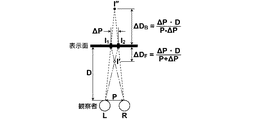
ここで、この現象について説明する。図5は右目用画像および左目用画像において互いに視差のある被写体の立体感の程度を説明するための図、図6は表示面から観察者までの距離により立体感が変化することを示すグラフである。 Here, this phenomenon will be described. FIG. 5 is a diagram for explaining the degree of stereoscopic effect of a subject with parallax in the right-eye image and the left-eye image, and FIG. 6 is a graph showing that the stereoscopic effect changes depending on the distance from the display surface to the observer. is there.
図5に示すように、表示面から観察者までの距離をDとすると、視差量がΔPの被写体Iの表示面からの飛び出し量ΔDFは(1)式のように表される。なお、視差方向が逆転した場合には被写体Iは表示面から引っ込んで見えるようになり、このときの引っ込み量ΔDBは(2)式のように表される。
ΔDF=ΔP・D/P+ΔP (1)
ΔDF=ΔP・D/P−ΔP (2)
As shown in FIG. 5, when the distance to the observer from the display surface is D, the pop-up amount [Delta] D F from the display surface of the object I parallax amount ΔP is expressed by the equation (1). In the case where the parallax direction is reversed subject I look as if they recessed from the display surface, retraction amount [Delta] D B at this time is expressed by the equation (2).
ΔD F = ΔP · D / P + ΔP (1)
ΔD F = ΔP · D / P−ΔP (2)
(1)式から分かる通り、被写体Iの表示面からの飛び出し量ΔDFは、表示面から観察者までの距離Dに比例するため、表示面から観察者までの距離が長くなるにつれて、立体視画像の立体感が大きくなることになる。なお、視差方向が逆転した場合、すなわち引っ込み量ΔDBについても同様に、表示面から観察者までの距離が長くなるにつれて、立体視画像の立体感が大きくなることになる。 As can be seen from the equation (1), since the projection amount ΔD F of the subject I from the display surface is proportional to the distance D from the display surface to the observer, the stereoscopic view is increased as the distance from the display surface to the observer is increased. The stereoscopic effect of the image will increase. In the case where the parallax direction is reversed, i.e. Similarly for retraction amount [Delta] D B, as the distance to the viewer from the display surface becomes long, so that the stereoscopic effect of the stereoscopic image is increased.
このような現象は、写真や映画等の一般的な立体視映像を鑑賞する場合には大きな問題とならないが、放射線画像診断のような医療系の分野において立体視画像を観察する場合には、観察者がモニタを見る位置によって患者の撮影部位の立体感が異なって見えるようになってしまうため、正確な診断を要する場合には好ましくない現象である。 Such a phenomenon is not a big problem when viewing general stereoscopic images such as photographs and movies, but when observing stereoscopic images in the medical field such as radiological image diagnosis, This is an undesirable phenomenon when an accurate diagnosis is required because the stereoscopic effect of the patient's imaging region differs depending on the position where the observer looks at the monitor.
本発明は、上記の事情に鑑み、右目用画像および左目用画像の2枚の画像を用いて立体視画像を表示する立体視画像表示装置において、観察者がモニタを見る位置により立体視画像の立体感が変化しにくくすることを目的とする。 In view of the above circumstances, the present invention provides a stereoscopic image display apparatus that displays a stereoscopic image using two images, a right-eye image and a left-eye image. The object is to make the stereoscopic effect difficult to change.
本発明の立体視画像表示装置は、互いに視差のある右目用画像および左目用画像からなる画像対から構成される立体視画像を観察者に立体視可能に表示する表示手段と、表示手段から観察者までの距離を特定する距離特定手段と、同一被写体について異なる輻輳角で撮影された複数の画像対のデータを記憶する画像データ記憶手段と、画像データ記憶手段に記憶されている複数の画像対のデータの中から、前記距離が長くなる程、表示手段に表示する画像対として輻輳角が小さい画像対を選択する画像対選択手段とを備えてなることを特徴とするものである。 The stereoscopic image display apparatus according to the present invention includes a display unit that displays a stereoscopic image composed of a pair of images for a right eye and a left eye that have a parallax to each other in a stereoscopic manner and allows the viewer to observe the stereoscopic image. Distance specifying means for specifying the distance to the person, image data storage means for storing data of a plurality of image pairs taken at different convergence angles for the same subject, and a plurality of image pairs stored in the image data storage means Image data selecting means for selecting an image pair having a smaller convergence angle as an image pair to be displayed on the display means as the distance increases.
ここで、距離特定手段は、前記距離を測定する測定手段を備え、測定手段により測定された距離を前記距離として特定するものとしてもよいし、前記距離に対応した情報の入力を受け付ける入力手段を備え、入力手段に入力された情報に基づいて距離を特定するものとしてもよい。 Here, the distance specifying means may include a measuring means for measuring the distance, and the distance measured by the measuring means may be specified as the distance, or an input means for receiving input of information corresponding to the distance. It is good also as what specifies and is based on the information input into the input means.
ここで「距離に対応した情報」とは、距離値そのものであってもよいし、例えば、一人で観察する場合には近距離観察が想定されるため、表示手段から観察者までの距離として近距離範囲が設定された単独観察モード、カンファレンス等で複数人数で表示手段を囲んで観察する場合には遠距離観察が想定されるため、表示手段から観察者までの距離として遠距離範囲が設定された複数観察モード等といった、距離に対応した情報であってもよい。 Here, the “information corresponding to the distance” may be the distance value itself. For example, when observing alone, near distance observation is assumed, so the distance from the display means to the observer is close. In a single observation mode where a distance range is set, in a conference, etc., when a plurality of people surround the display means for observation, a long distance range is assumed, so a long distance range is set as the distance from the display means to the observer. Information corresponding to distance, such as a multiple observation mode, may also be used.
本発明の立体視画像表示装置によれば、同一被写体について異なる輻輳角で撮影された複数の画像対のデータを用意しておき、表示手段から観察者までの距離が長くなる程、表示手段に表示する画像対として輻輳角が小さい画像対、すなわち立体視画像の立体感が小さい画像対を選択するようにしたので、観察者がモニタを見る位置により立体視画像の立体感が変化しにくくすることができる。 According to the stereoscopic image display apparatus of the present invention, data of a plurality of image pairs photographed at different convergence angles for the same subject is prepared, and the longer the distance from the display means to the observer, the more the display means As the image pair to be displayed, an image pair with a small convergence angle, that is, an image pair with a small stereoscopic effect of the stereoscopic image is selected, so that the stereoscopic effect of the stereoscopic image hardly changes depending on the position where the observer looks at the monitor. be able to.
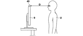
以下、図面を参照して本発明の立体視画像表示装置の一実施の形態を用いた乳房用立体視画像撮影表示システムについて説明する。まず、本実施の形態の乳房用立体視画像撮影表示システム全体の概略構成について説明する。図1は乳房用立体視画像撮影表示システムの概略構成を示す図、図2は上記乳房用立体視画像撮影表示システムのアーム部を図1の右方向から見た図、図3は上記乳房用立体視画像撮影表示システムのコンピュータ内部の概略構成を示すブロック図、図4は上記乳房用立体視画像撮影表示システムのモニタの構成図である。 Hereinafter, a stereoscopic image capturing and displaying system for breasts using an embodiment of a stereoscopic image display device of the present invention will be described with reference to the drawings. First, a schematic configuration of the whole breast stereoscopic image photographing / displaying system according to the present embodiment will be described. FIG. 1 is a diagram showing a schematic configuration of a breast stereoscopic image photographing / displaying system, FIG. 2 is a diagram of the arm part of the breast stereoscopic image photographing / displaying system as viewed from the right in FIG. 1, and FIG. FIG. 4 is a block diagram showing a schematic configuration inside the computer of the stereoscopic image capturing / display system, and FIG. 4 is a configuration diagram of a monitor of the breast stereoscopic image capturing / display system.
本実施形態の乳房用立体視画像撮影表示システム1は、図1に示すように、乳房画像撮影装置10と、乳房画像撮影装置10に接続されたコンピュータ8と、コンピュータ8に接続されたモニタ9および入力部7とを備えている。
As shown in FIG. 1, a breast stereoscopic imaging and displaying
そして、乳房画像撮影装置10は、図1に示すように、基台11と、基台11に対し上下方向(Z方向)に移動可能であり、かつ回転可能な回転軸12と、回転軸12により基台11と連結されたアーム部13を備えている。なお、図2には、図1の右方向から見たアーム部13を示している。
As shown in FIG. 1, the
アーム部13はアルファベットのCの形をしており、その一端には撮影台14が、その他端には撮影台14と対向するように放射線照射部16が取り付けられている。アーム部13の回転および上下方向の移動は、基台11に組み込まれたアームコントローラ31により制御される。
The
撮影台14の内部には、フラットパネルディテクタ等の放射線画像検出器15と、放射線画像検出器15からの電荷信号の読み出しを制御する検出器コントローラ33が備えられている。また、撮影台14の内部には、放射線画像検出器15から読み出された電荷信号を電圧信号に変換するチャージアンプや、チャージアンプから出力された電圧信号をサンプリングする相関2重サンプリング回路や、電圧信号をデジタル信号に変換するAD変換部などが設けられた回路基板なども設置されている。
A
また、撮影台14はアーム部13に対し回転可能に構成されており、基台11に対してアーム部13が回転したときでも、撮影台14の向きは基台11に対し固定された向きとすることができる。
In addition, the photographing table 14 is configured to be rotatable with respect to the
放射線画像検出器15は、放射線画像の記録と読出しを繰り返して行うことができるものであり、放射線の照射を直接受けて電荷を発生する、いわゆる直接型の放射線画像検出器を用いてもよいし、放射線を一旦可視光に変換し、その可視光を電荷信号に変換する、いわゆる間接型の放射線画像検出器を用いるようにしてもよい。また、放射線画像信号の読出方式としては、TFT(thin film transistor)スイッチをオン・オフされることによって放射線画像信号が読みだされる、いわゆるTFT読出方式のものや、読取光を照射することによって放射線画像信号が読み出される、いわゆる光読出方式のものを用いることが望ましいが、これに限らずその他のものを用いるようにしてもよい。
The
放射線照射部16の中には放射線源17と、放射線源コントローラ32が収納されている。放射線源コントローラ32は、放射線源17から放射線を照射するタイミングと、放射線源17における放射線発生条件(管電流、管電圧、時間等)を制御するものである。
A
また、アーム部13の中央部には、撮影台14の上方に配置されて乳房Mを押さえつけて圧迫する圧迫板18と、その圧迫板18を支持する支持部20と、支持部20を上下方向(Z方向)に移動させる移動機構19が設けられている。圧迫板18の位置、圧迫圧は、圧迫板コントローラ34により制御される。
Further, in the central portion of the
コンピュータ8は、中央処理装置(CPU)および半導体メモリやハードディスクやSSD等のストレージデバイスなどを備えており、これらのハードウェアによって、図3に示すような制御部8a、データ記憶部8bおよび画像対選択部8cが構成されている。
The
制御部8aは、各種のコントローラ31〜34に対して所定の制御信号を出力し、システム全体の制御を行うものである。具体的な制御方法については後で詳述する。
The
データ記憶部8bは、同一被写体について異なる輻輳角で撮影された複数の画像対のデータ等を記憶するものである。
The
画像対選択部8cは、データ記憶部8bに記憶されている複数の画像対のデータの中から、モニタ9に表示する画像対を選択する機能を有するものである。
The image
入力部7は、例えば、キーボードやマウスなどのポインティングデバイスから構成されたものであり、撮影条件や操作指示等の入力を受け付けるためのものである。
The
モニタ9は、コンピュータ8から出力された2つの放射線画像信号(画像対のデータ)を用いて、撮影方向毎の放射線画像をそれぞれ2次元画像として表示することにより、立体視画像を立体視可能に表示するように構成されたものである。
The
立体視画像を表示する構成としては、たとえば、2つの画面を用いて2つの放射線画像信号に基づく放射線画像をそれぞれ表示させて、これらをハーフミラーや偏光グラスなどを用いることで一方の放射線画像は観察者の右目に入射させ、他方の放射線画像は観察者の左目に入射させることによって立体視画像を表示する構成を採用することができる。 As a configuration for displaying a stereoscopic image, for example, radiographic images based on two radiographic image signals are displayed using two screens, and one radiographic image is obtained by using a half mirror or a polarizing glass. It is possible to adopt a configuration in which a stereoscopic image is displayed by being incident on the observer's right eye and the other radiation image being incident on the observer's left eye.
または、たとえば、2つの放射線画像を所定の視差量だけずらして重ね合わせて表示し、これを偏光グラスで観察することで立体視画像を生成する構成としてもよいし、もしくはパララックスバリア方式およびレンチキュラー方式のように、2つの放射線画像を立体視可能な3D液晶に表示することによって立体視画像を生成する構成としてもよい。 Alternatively, for example, two radiographic images may be displayed by being shifted by a predetermined amount of parallax and superimposed, and a stereoscopic image may be generated by observing this with a polarizing glass, or a parallax barrier method and a lenticular It is good also as a structure which produces | generates a stereoscopic vision image by displaying on a 3D liquid crystal in which two radiographic images can be stereoscopically viewed like a system.
また、立体視画像を表示する装置と2次元画像を表示する装置とは別個に構成するようにしてもよいし、同じ画面上で表示できる場合には同じ装置として構成するようにしてもよい。 In addition, a device that displays a stereoscopic image and a device that displays a two-dimensional image may be configured separately, or may be configured as the same device if they can be displayed on the same screen.
このモニタ9は、モニタ9の表示面から観察者までの距離を測定する距離測定手段40を備えている。この距離測定手段40については、超音波距離センサー、レーザー距離センサー、もしくはステレオカメラにより撮影された画像中の特定の被写体について、画像間の視差により距離を算出するシステム等、どのようなものを用いてもよいが、特にステレオカメラを用いたシステムにおいて、既知の顔認識技術により画像中から観察者の顔(好ましくは目)を検出し、モニタ9の表示面から観察者の顔(好ましくは目)までの距離を算出するようにすれば、本発明の処理に即して正確に距離の測定を行うことができる。
The
次に、本実施形態の乳房用立体視画像撮影表示システムの作用について説明する。 Next, the operation of the breast stereoscopic image capturing and displaying system according to the present embodiment will be described.
まず、撮影の際の動作について説明する。 First, the operation at the time of shooting will be described.
最初に撮影台14の上に乳房Mが設置され、圧迫板18により乳房Mが所定の圧力によって圧迫される。
First, the breast M is set on the imaging table 14, and the breast M is compressed with a predetermined pressure by the
次に、入力部7おいて、2つの異なる撮影方向がなす角度(以下、輻輳角θという)および輻輳角θを構成する撮影角度θ'の組み合わせを含む種々の撮影条件が入力された後、撮影開始の指示が入力される。
Next, after various imaging conditions including a combination of an angle formed by two different imaging directions (hereinafter referred to as a convergence angle θ) and an imaging angle θ ′ constituting the convergence angle θ are input in the
そして、入力部7において撮影開始の指示があると、乳房Mの立体視画像の撮影が行われる。具体的には、まず、制御部8aが、輻輳角θと輻輳角θを構成する撮影角度θ'の情報をアームコントローラ31に出力する。なお、本実施形態においては、このときの輻輳角θの情報としてθ=4°、輻輳角θを構成する撮影角度θ’の組み合わせとしてθ’=±2°の組み合わせが入力されたものとするが、これに限られるものではなく、撮影者は入力部7において任意の輻輳角θを設定可能である。
Then, when there is an instruction to start photographing at the
アームコントローラ31において、制御部8aから出力された撮影角度θ’の情報が受け付けられ、アームコントローラ31は、この撮影角度θ’の情報に基づいて、まず右目用の放射線画像を撮影するためにアーム部13を検出面15aに垂直な方向に対して+2°傾く撮影角度θ'となる制御信号を出力する。
The
アームコントローラ31から出力された制御信号に応じてアーム部13が+2°の位置まで回転する。続いて制御部8aは、放射線源コントローラ32および検出器コントローラ33に対して放射線の照射と放射線画像信号の読出しを行うよう制御信号を出力する。この制御信号に応じて、放射線源17から放射線が照射され、乳房Mを撮影角度θ'が+2°の方向から撮影した放射線画像が放射線検出器15によって検出され、検出器コントローラ33によって放射線画像信号が読み出され、コンピュータ8のデータ記憶部8bに記憶される。
In response to the control signal output from the
続いて、まず左目用の放射線画像を撮影するためにアーム部13を検出面15aに垂直な方向に対して−2°傾く撮影角度θ'となる制御信号を出力する。
Subsequently, in order to capture a radiographic image for the left eye, a control signal that outputs an imaging angle θ ′ in which the
アームコントローラ31から出力された制御信号に応じてアーム部13が−2°の位置まで回転する。続いて制御部8aは、放射線源コントローラ32および検出器コントローラ33に対して放射線の照射と放射線画像信号の読出しを行うよう制御信号を出力する。この制御信号に応じて、放射線源17から放射線が照射され、乳房Mを撮影角度θ'が−2°の方向から撮影した放射線画像が放射線検出器15によって検出され、検出器コントローラ33によって放射線画像信号が読み出され、コンピュータ8のデータ記憶部8bに記憶される。
In response to the control signal output from the
上記の通り、ユーザーに指定された輻輳角での撮影が終了した後、さらにユーザーに指定された輻輳角の半分の輻輳角で追加撮影を行う。本実施の形態においては、輻輳角θの情報としてθ=4°、輻輳角θを構成する撮影角度θ’の組み合わせとしてθ’=±2°の組み合わせが入力されているので、追加の撮影では、輻輳角θ=2°、輻輳角θを構成する撮影角度θ’の組み合わせとしてθ’=±1°の組み合わせで、上記と同様の手順で追加撮影を行う。 As described above, after photographing at the convergence angle designated by the user is completed, additional photographing is performed at a convergence angle that is half the convergence angle designated by the user. In the present embodiment, θ = 4 ° is input as information on the convergence angle θ, and a combination of θ ′ = ± 2 ° is input as a combination of the imaging angles θ ′ constituting the convergence angle θ. Further, a combination of θ ′ = ± 1 ° as a combination of the convergence angle θ = 2 ° and the imaging angle θ ′ constituting the convergence angle θ, and additional imaging is performed in the same procedure as described above.
その結果、データ記憶部8bには、同一被写体について輻輳角θ=4°で撮影した画像対(右目用放射線画像および左目用放射線画像)のデータと、輻輳角θ=2°で撮影した画像対のデータが記憶されることになる。
As a result, the
次に、立体視画像表示の際の動作について説明する。 Next, an operation for displaying a stereoscopic image will be described.
上記で説明の通り、立体視画像を観察する場合、立体視画像を表示するモニタ9から観察者までの距離が長くなるにつれて、立体視画像の立体感が大きくなるという現象が発生する。このような現象は、放射線画像診断のような医療系の分野において立体視画像を観察する場合には、観察者がモニタ9を見る位置によって患者の撮影部位の立体感が異なって見えるようになってしまうため、正確な診断を要する場合には好ましくない現象である。
As described above, when a stereoscopic image is observed, the stereoscopic effect of the stereoscopic image increases as the distance from the
従って、本発明ではこのような問題を解消するために、まず、モニタ9の距離測定手段40において、モニタ9の表示面から観察者までの距離を測定する。
Therefore, in the present invention, in order to solve such a problem, first, the distance measuring means 40 of the
画像対選択部8cは、上記で測定した距離が70cm未満であった場合には、輻輳角θ=4°で撮影した画像対のデータをデータ記憶部8bからモニタ9に送信させ、上記で測定した距離が70cm以上であった場合には、輻輳角θ=2°で撮影した画像対のデータをデータ記憶部8bからモニタ9に送信させる。なお、ここでの閾値は上記に限るものではなく、モニタ9の大きさや設置環境等を考慮し、適切なものを選択すればよい。
When the distance measured above is less than 70 cm, the image
モニタ9は、データ記憶部8bから受信した画像対のデータを基に、乳房Mの立体視画像を表示させる。
The
上記の通り、モニタ9から観察者までの距離が長くなる程、モニタ9に表示する画像対として輻輳角が小さい画像対、すなわち立体視画像の立体感が小さい画像対を選択するようにしたので、観察者がモニタ9を見る位置により立体視画像の立体感が変化しにくくすることができる。
As described above, as the distance from the
なお、上記実施の形態の説明では、追加撮影時において、ユーザーに指定された輻輳角の半分の輻輳角で追加撮影を行っているが、これに限らず、どのような態様としてもよい。 In the description of the above embodiment, additional shooting is performed at a convergence angle that is half of the convergence angle designated by the user at the time of additional shooting. However, the present invention is not limited to this, and any mode may be used.
また、モニタ9から観察者までの距離の特定は、立体視画像表示時に一度だけ行ってもよいし、立体視画像表示中も定期的(例えば1秒に1回等)に距離の特定を行い、距離が変化した場合には、それに合わせて画像を切り替えるようにしてもよい。
Further, the distance from the
また、上記実施の形態の説明では、同一被写体に対して2種類の輻輳角で撮影した画像対を取得しているが、取得する画像対の数については特に限定はなく、どのような態様としてもよい。取得する画像対の数を2つとすれば、余計な撮影の回数が少なく本発明を実現でき、逆に取得する画像対の数を多くする程、モニタ9から観察者までの距離に従って、より滑らかに画像の切り替えを行うことができるが、その分余計な撮影の回数が多くなり患者の被曝量も増加してしまうので、状況により適切な数を選択することができる。
In the description of the above embodiment, image pairs captured with two types of convergence angles are acquired for the same subject. However, the number of image pairs to be acquired is not particularly limited, and as an aspect Also good. If the number of image pairs to be acquired is two, the present invention can be realized with a smaller number of unnecessary photographing, and conversely, the greater the number of image pairs to be acquired, the smoother the distance from the
また、上記実施の形態の説明では、距離測定手段40を設けてモニタ9の表示面から観察者までの距離の特定を行っているが、これに限らず、入力部7においてユーザーから距離に対応した情報の入力を受け付け、これに基づいて距離の特定を行ってもよい。
In the description of the above embodiment, the
ここで「距離に対応した情報」とは、距離値そのものであってもよいし、例えば、一人で観察する場合には近距離観察が想定されるため、モニタ9の表示面から観察者までの距離として近距離範囲が設定された単独観察モード、カンファレンス等で複数人数でモニタ9を囲んで観察する場合には遠距離観察が想定されるため、モニタ9の表示面から観察者までの距離として遠距離範囲が設定された複数観察モード等といった、距離に対応した情報であってもよい。
Here, the “information corresponding to the distance” may be the distance value itself. For example, when observing alone, near-distance observation is assumed, and therefore, from the display surface of the
また、本発明の立体視画像表示装置の一実施の形態として、乳房用立体視画像撮影表示システムに適用した例を示したが、本発明は乳房用立体視画像撮影表示システムに限定されるものではなく、立体視画像を表示可能な立体視画像表示装置であればどのような装置にも適用することができる。 In addition, as an embodiment of the stereoscopic image display device of the present invention, an example applied to a breast stereoscopic image photographing display system has been shown. However, the present invention is limited to a breast stereoscopic image photographing display system. Instead, the present invention can be applied to any device as long as it can display a stereoscopic image.
また、上記以外にも、本発明の要旨を逸脱しない範囲において、各種の改良や変形を行なってもよいのは勿論である。 In addition to the above, it goes without saying that various improvements and modifications may be made without departing from the scope of the present invention.
1 乳房用立体視画像撮影表示システム
7 入力部
8 コンピュータ
8a 制御部
8b データ記憶部
8c 画像対選択部
9 モニタ
10 乳房画像撮影装置
11 基台
12 回転軸
13 アーム部
14 撮影台
15 放射線画像検出器
16 放射線照射部
17 放射線源
18 圧迫板
31 アームコントローラ
32 放射線源コントローラ
33 検出器コントローラ
34 圧迫板コントローラ
40 距離測定手段
DESCRIPTION OF
Claims (3)
該表示手段から前記観察者までの距離を特定する距離特定手段と、
同一被写体について異なる輻輳角で撮影された複数の画像対のデータを記憶する画像データ記憶手段と、
該画像データ記憶手段に記憶されている複数の画像対のデータの中から、前記距離が長くなる程、前記表示手段に表示する画像対として輻輳角が小さい画像対を選択する画像対選択手段とを備えてなることを特徴とする立体視画像表示装置。 Display means for displaying a stereoscopic image composed of a pair of images including a right-eye image and a left-eye image having parallax with each other so as to be stereoscopically viewed by an observer;
Distance specifying means for specifying the distance from the display means to the observer;
Image data storage means for storing data of a plurality of image pairs photographed at different convergence angles for the same subject;
Image pair selection means for selecting an image pair having a smaller convergence angle as an image pair to be displayed on the display means as the distance becomes longer, from a plurality of image pair data stored in the image data storage means; A stereoscopic image display device comprising:
Applications Claiming Priority (2)
| Application Number | Priority Date | Filing Date | Title |
|---|---|---|---|
| US201161440525P | 2011-02-08 | 2011-02-08 | |
| US61/440525 | 2011-02-08 |
Publications (1)
| Publication Number | Publication Date |
|---|---|
| JP2012165358A true JP2012165358A (en) | 2012-08-30 |
Family
ID=46844277
Family Applications (1)
| Application Number | Title | Priority Date | Filing Date |
|---|---|---|---|
| JP2011176596A Withdrawn JP2012165358A (en) | 2011-02-08 | 2011-08-12 | Stereoscopic image display device |
Country Status (1)
| Country | Link |
|---|---|
| JP (1) | JP2012165358A (en) |
Cited By (3)
| Publication number | Priority date | Publication date | Assignee | Title |
|---|---|---|---|---|
| WO2014092147A1 (en) * | 2012-12-12 | 2014-06-19 | 株式会社 東芝 | X-ray diagnostic apparatus and medical image display apparatus |
| WO2019111473A1 (en) * | 2017-12-06 | 2019-06-13 | ソニー・オリンパスメディカルソリューションズ株式会社 | Medical control device and medical observation system |
| CN114520905A (en) * | 2020-11-19 | 2022-05-20 | 京东方科技集团股份有限公司 | Image processing method, image display method and image display system |
-
2011
- 2011-08-12 JP JP2011176596A patent/JP2012165358A/en not_active Withdrawn
Cited By (8)
| Publication number | Priority date | Publication date | Assignee | Title |
|---|---|---|---|---|
| WO2014092147A1 (en) * | 2012-12-12 | 2014-06-19 | 株式会社 東芝 | X-ray diagnostic apparatus and medical image display apparatus |
| JP2014133103A (en) * | 2012-12-12 | 2014-07-24 | Toshiba Corp | X-ray diagnostic apparatus and medical image display apparatus |
| US9986962B2 (en) | 2012-12-12 | 2018-06-05 | Toshiba Medical Systems Corporation | Medical image display apparatus and X-ray diagnosis apparatus |
| WO2019111473A1 (en) * | 2017-12-06 | 2019-06-13 | ソニー・オリンパスメディカルソリューションズ株式会社 | Medical control device and medical observation system |
| JPWO2019111473A1 (en) * | 2017-12-06 | 2020-12-03 | ソニー・オリンパスメディカルソリューションズ株式会社 | Medical control device and medical observation system |
| CN114520905A (en) * | 2020-11-19 | 2022-05-20 | 京东方科技集团股份有限公司 | Image processing method, image display method and image display system |
| US11800079B2 (en) | 2020-11-19 | 2023-10-24 | Beijing Boe Optoelectronics Technology Co., Ltd. | Image processing method, image display method and image display system |
| CN114520905B (en) * | 2020-11-19 | 2024-04-19 | 京东方科技集团股份有限公司 | Image processing method, image display method and image display system |
Similar Documents
| Publication | Publication Date | Title |
|---|---|---|
| JP2012050519A (en) | Mammographic apparatus | |
| JP2012029742A (en) | Radiological image capturing and displaying method and apparatus | |
| JP2012165358A (en) | Stereoscopic image display device | |
| JP2012029759A (en) | Radiological image radiographing and displaying method and apparatus | |
| JP2012024519A (en) | Radiological image radiographing and displaying method and apparatus | |
| JP5658818B2 (en) | Radiation breast image display method, radiation breast image display apparatus and program | |
| JP2012066049A (en) | Radiation imaging apparatus and stereoscopic image display method | |
| JP5695524B2 (en) | Stereoscopic image display apparatus and method, and program | |
| JP2011200408A (en) | Method and system for radiographing and displaying radiation image | |
| WO2012056695A1 (en) | Three-dimensional image display device, method, and program | |
| JP2012170044A (en) | Stereoscopic image display device | |
| WO2012108201A1 (en) | Stereoscopic image display device | |
| WO2012105188A1 (en) | Stereoscopic image display device and method, and program | |
| WO2012056679A1 (en) | 3d image display system and 3d image display device | |
| WO2012063418A1 (en) | Stereoscopic image display device and method, and program | |
| WO2012056677A1 (en) | Three-dimensional image display device | |
| WO2012063419A1 (en) | Stereoscopic image display device and method, and program | |
| WO2012056718A1 (en) | Three-dimensional radiation image display device, method, and program | |
| WO2012029705A1 (en) | Device and method for delivering images | |
| JP2012024516A (en) | Radiological image radiographing and displaying method and apparatus | |
| JP2012068610A (en) | Stereoscopic vision image display device, radiation image photographing and display system and stereoscopic vision image display method | |
| WO2012132453A1 (en) | Radiological breast-image display method, radiological breast-image display device, and programme | |
| JP2012050518A (en) | Radiation imaging apparatus | |
| WO2012039126A1 (en) | Radiation image capturing device, image data compression device and image data compression method | |
| WO2012056680A1 (en) | 3d image display device |
Legal Events
| Date | Code | Title | Description |
|---|---|---|---|
| A300 | Application deemed to be withdrawn because no request for examination was validly filed |
Free format text: JAPANESE INTERMEDIATE CODE: A300 Effective date: 20141104 |