JP2012162903A - Road expansion joint - Google Patents
Road expansion joint Download PDFInfo
- Publication number
- JP2012162903A JP2012162903A JP2011023492A JP2011023492A JP2012162903A JP 2012162903 A JP2012162903 A JP 2012162903A JP 2011023492 A JP2011023492 A JP 2011023492A JP 2011023492 A JP2011023492 A JP 2011023492A JP 2012162903 A JP2012162903 A JP 2012162903A
- Authority
- JP
- Japan
- Prior art keywords
- fingers
- impact
- pavement
- cushioning material
- absorbing material
- Prior art date
- Legal status (The legal status is an assumption and is not a legal conclusion. Google has not performed a legal analysis and makes no representation as to the accuracy of the status listed.)
- Pending
Links
Images


Abstract
Description
本発明は、遊間を挟んで互いに櫛歯状の先端部を対向させた双方のフィンガー上に衝撃緩衝材を固定させた道路用伸縮継手に関するものである。 The present invention relates to an expansion joint for roads in which an impact cushioning material is fixed on both fingers facing each other with comb-shaped tips facing each other with a gap therebetween.
この種の伸縮継手としては、特許文献1に開示されたものが知られている。
この公知の伸縮継手は、道路の伸縮遊間を形成して対向している桁端側の上部を切り欠いて凹部を形成し、その中に、鋼材からなる一対の櫛歯状フィンガーの先端部を遊間上で対向させた状態で伸縮継手を装置し、両フィンガーの上面にゴムなどからなる衝撃緩衝材を装着固定する構成を採用していて、路面を走行する車両に起因する騒音や振動を低減させようとしたものである(段落番号[0014〜0015]の実施態様4及び図4参照)。
As this type of expansion joint, the one disclosed in
This known expansion joint forms a recess by notching the upper part of the opposite end of the spar that forms the expansion / contraction play of the road, and the tip of a pair of comb-like fingers made of steel is contained therein. The expansion joint is installed in the state of facing the gap, and the shock absorber made of rubber or the like is installed and fixed on the upper surface of both fingers, reducing noise and vibration caused by vehicles traveling on the road surface. (See
しかしながら、この継手では、舗装部の端面と鋼材からなるフィンガーの後端面とが直接当接する状態となっている。そのため、気温の変化に伴ってフィンガーが伸縮すると舗装部の端面がフィンガーの押圧力を繰り返し受けることになる。また、車両の走行に伴って生じる微細な振動波に起因して舗装部とフィンガーの後端部との衝突や摺動を惹起させることになる。
そのため、コンクリートやアスファルトからなる舗装部の端面に圧縮力や摩擦力が働き、舗装部の端部にクラックや欠けが生じて舗装部とフィンガーとの間に新たな隙間が形成され、この隙間が車両の通過時の新たな騒音源となる問題があった。
However, in this joint, the end surface of the pavement and the rear end surface of the finger made of steel are in direct contact with each other. Therefore, when a finger expands and contracts with a change in temperature, the end surface of the pavement part repeatedly receives the pressing force of the finger. Further, collision and sliding between the paved portion and the rear end portion of the finger are caused due to minute vibration waves generated as the vehicle travels.
Therefore, compressive force and frictional force act on the end surface of the pavement made of concrete or asphalt, cracks and chips occur at the end of the pavement, and a new gap is formed between the pavement and the finger. There was a problem that became a new noise source when the vehicle passed.
本発明は、遊間を挟んで互いに櫛歯状の先端部を対向させた双方のフィンガー上に衝撃緩衝材を固定させた道路用伸縮継手において、気温の変化に起因するフィンガーの伸縮時の押圧力や車両通過時の微細な振動を吸収して舗装部の端部への伝達を抑制することを課題としたものである。 The present invention relates to a road expansion joint in which an impact cushioning material is fixed on both fingers facing each other with comb-shaped tips facing each other with a gap between them. Another object of the present invention is to suppress the transmission to the end of the pavement by absorbing minute vibrations when passing through the vehicle.
この課題を解決するための技術的手段は、イ)衝撃緩衝材からフィンガーの先端部及び後端部の外壁面に沿う側壁を突設して当該外壁面に固定し、ロ)衝撃緩衝材の後端から上面が衝撃緩衝材と面一で下面を傾斜させた先細り状の庇を延設して舗装部上に重合接着させられるようにしたこと、である。 Technical means for solving this problem are as follows: a) Side walls along the outer wall surfaces of the front and rear ends of the fingers are projected from the shock absorbing material and fixed to the outer wall surface; The taper-shaped ridges whose upper surface is flush with the shock-absorbing material from the rear end and whose lower surface is inclined are extended so as to be superposed on the pavement.
この技術的手段において、衝撃緩衝材からフィンガーの先端部及び後端部の外壁面に沿う側壁が突設され、それが当該外壁面に固定されているから、衝撃緩衝材は、フィンガーの先端面、頂面及び後端面の三面において固定されることになり、その固定力は強固なものとなる。しかも、舗装部の端部とフィンガーの後端部との間には衝撃緩衝材が介在することになるから、気温の変化に起因するフィンガーの伸縮に伴う押圧力や車両通過時の微細な振動が吸収され、フィンガーの舗装部の端部への衝撃が吸収されることになる。
衝撃緩衝材の後端からは舗装部上に重合接着させるための庇が延設されている。この庇は、上面が衝撃緩衝材と面一で下面を傾斜させた先細り状のものとなっているから、その上を通過する車両は舗装部から衝撃緩衝材側へ徐々に移動してフィンガー上に達することになる。この庇は、舗装部の端部を覆ってこれを保護する機能を発揮する。
したがって、衝撃緩衝材は、フィンガーや車両の走行に起因する衝撃や振動を舗装部の端部へ伝達することを抑制することになる。
In this technical means, since the side walls along the outer wall surfaces of the front end portion and the rear end portion of the finger protrude from the shock absorbing material and are fixed to the outer wall surface, the shock absorbing material is provided on the front end surface of the finger. The top surface and the rear end surface are fixed to each other, and the fixing force is strong. In addition, since an impact buffering material is interposed between the end of the pavement and the rear end of the finger, the pressing force accompanying the expansion and contraction of the finger due to the change in temperature and the minute vibration when passing through the vehicle Is absorbed, and the impact on the end of the paved portion of the finger is absorbed.
From the rear end of the shock-absorbing material, a ridge is attached on the pavement for polymerization adhesion. This kite has a tapered shape with the upper surface flush with the shock absorbing material and the lower surface inclined, so that the vehicle passing over it gradually moves from the pavement to the shock absorbing material and moves on the fingers. Will be reached. This kite functions to cover and protect the end of the pavement.
Therefore, the shock absorbing material suppresses transmission of shocks and vibrations caused by the fingers and the traveling of the vehicle to the end of the pavement.
衝撃緩衝材としては、クロロプレンゴムなどの耐久性のよい合成ゴムを好適に使用することができる。
衝撃緩衝材の厚みは、3〜30mm程度が望ましく、通過する車両の種類や通行量を勘案して設計することになる。
また、衝撃緩衝材の庇下面の傾斜角は、30〜60度の範囲で選択すればよい。これより小さすぎると庇が長くなり過ぎて庇の先端部分が薄肉となり、摩耗などによって剥離しやすくなるし、大きすぎると庇と舗装面部の上面とがうまく重合しないことになる。舗装層を形成する作業のし易さを考慮すると40〜50度程度が好ましい。
As the impact buffer material, a highly durable synthetic rubber such as chloroprene rubber can be suitably used.
The thickness of the shock-absorbing material is preferably about 3 to 30 mm, and is designed in consideration of the type of vehicle passing and the amount of traffic.
Moreover, what is necessary is just to select the inclination-angle of the heel lower surface of a shock-absorbing material in the range of 30-60 degrees. If it is too small, the heel becomes too long and the tip of the heel becomes thin and easily peels off due to wear or the like. If it is too large, the heel and the upper surface of the pavement surface portion do not polymerize well. Considering the ease of work for forming the pavement layer, about 40 to 50 degrees is preferable.
フィンガーの熱に起因する伸縮時の押圧力や車両通過時の微細な振動を吸収して舗装部の端部への伝達が抑制される結果、舗装部の端部にクラックや欠けがほとんど発生しない利点があり、舗装部とフィンガーとの間に新たな騒音源や振動源となる隙間が発生することもない。 As a result of absorbing the pressing force at the time of expansion and contraction due to the heat of the fingers and the minute vibration when passing through the vehicle and suppressing the transmission to the end of the pavement, there is almost no crack or chipping at the end of the pavement There is an advantage, and a gap as a new noise source or vibration source does not occur between the pavement and the finger.
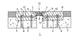
図1は、道路の伸縮遊間1の断面を示したもので、相対向する道路桁2、2の端部を切り欠いて形成した凹部3内に伸縮継手10を装置した状態を示している。
伸縮継手10は、図2に示したフィンガー11を凹部3内に装置し、フィンガー11、11から横方向へ突出させた支持杆12、12をアンカー4、4及び鉄筋5、5を用いて伸縮継手10を道路桁2、2に固定し、凹部3内に舗装材6、6を充填している。
なお、符号8は、フィンガー11、11間から雨水などが落下しないように配置した弾性シール材である。
FIG. 1 shows a cross section of an expansion /
The
In addition, the code | symbol 8 is an elastic sealing material arrange | positioned so that rainwater etc. may not fall between the
各フィンガー11、11の上部は、肉厚を20mmとしたクロロプレンゴムからなる衝撃緩衝材16、16で覆われている。衝撃緩衝材16は、フィンガー11、11の先端部13及び後端部14の外壁面に沿うように側壁が突設させてあって、フィンガーの先端部13外壁、頂面15及び後端部外壁14の前面にそれぞれ固定されている。衝撃緩衝材16の固定は、成形後に接着剤を用いて固定する他、成形時に焼付け接着させるようにしてもよい。
The upper portions of the
また、衝撃緩衝材16の後端(フィンガーの後端部14外壁の外側に固定される側壁)からは、上面を衝撃緩衝材16と面一となし下面を傾斜させた先細り状の庇17、17が延設されている。この庇17は凹部3内に充填される舗装材6、6のコーナー7、7上に接着され、舗装材6、6のコーナー7、7を保護することになる。
Further, from the rear end of the shock absorbing material 16 (side wall fixed to the outside of the outer wall of the
なお、衝撃緩衝材16の上を通過する車両のスリップを防止するために、衝撃緩衝材16の表面に図示しない凹凸を形成しておくことが望ましい。この凹凸は、ここで騒音が発生しないように、高さ、間隔及び形状を設計しておく必要がある。
In addition, in order to prevent the slip of the vehicle passing over the shock-absorbing
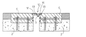
図4は他の実施形態における道路の伸縮遊間の断面を示したもので、この実施形態では、相対向するフィンガーの先端部13、13に沿わせた衝撃緩衝材16、16の側壁同志を連結させて樋9を形成した継手10を採用している。樋9も同じゴム材料で形成されているから、道路遊間の伸縮には対応させることができる。
なお、遊間からの水の排水については、別に製作した樋をフィンガー11、11間、または桁2、2間に取り付けるようにしてもよいのは勿論である。
FIG. 4 shows a cross section between the expansion and contraction of the road in another embodiment. In this embodiment, the side walls of the
Of course, for draining water from the gap, it is of course possible to attach a separately manufactured gutter between the
1伸縮遊間、 2道路桁、 3継手を装置するための凹部、 4アンカー、 5鉄筋、 6舗装材、 7舗装材のコーナー部、 8シール材、 9樋、 10伸縮継手、 11フィンガー、 12固定用の支持杆、 13フィンガー先端部、 14フィンガー後端部、 15フィンガー頂部、 16衝撃緩衝材、 17庇
1 expansion gap, 2 road girders, 3 recesses to install joints, 4 anchors, 5 reinforcing bars, 6 pavement materials, 7 pavement corners, 8 seal materials, 9 mm, 10 expansion joints, 11 fingers, 12 fixed Supporting rod for use, 13 finger tip, 14 finger rear end, 15 finger top, 16 shock absorber, 17 庇
Claims (1)
In an expansion joint for roads, where shock absorbing material is fixed on both fingers facing each other with a gap between them, side walls along the outer wall surfaces of the front and rear ends of the fingers protrude from the shock absorbing material. In addition to being fixed to the outer wall surface, from the rear end of the shock absorbing material, a taper-shaped ridge with the upper surface flush with the shock absorbing material and the lower surface inclined is superposed and bonded onto the pavement. Expansion joint
Priority Applications (1)
| Application Number | Priority Date | Filing Date | Title |
|---|---|---|---|
| JP2011023492A JP2012162903A (en) | 2011-02-07 | 2011-02-07 | Road expansion joint |
Applications Claiming Priority (1)
| Application Number | Priority Date | Filing Date | Title |
|---|---|---|---|
| JP2011023492A JP2012162903A (en) | 2011-02-07 | 2011-02-07 | Road expansion joint |
Publications (1)
| Publication Number | Publication Date |
|---|---|
| JP2012162903A true JP2012162903A (en) | 2012-08-30 |
Family
ID=46842546
Family Applications (1)
| Application Number | Title | Priority Date | Filing Date |
|---|---|---|---|
| JP2011023492A Pending JP2012162903A (en) | 2011-02-07 | 2011-02-07 | Road expansion joint |
Country Status (1)
| Country | Link |
|---|---|
| JP (1) | JP2012162903A (en) |
Citations (2)
| Publication number | Priority date | Publication date | Assignee | Title |
|---|---|---|---|---|
| JPS5664003A (en) * | 1979-10-29 | 1981-06-01 | Motonosuke Arai | Extensible apparatus of road splicing portion |
| JPS5934305A (en) * | 1982-07-23 | 1984-02-24 | エイエルエイチ・システムズ・リミテツド | Expansion joint and formation thereof |
-
2011
- 2011-02-07 JP JP2011023492A patent/JP2012162903A/en active Pending
Patent Citations (2)
| Publication number | Priority date | Publication date | Assignee | Title |
|---|---|---|---|---|
| JPS5664003A (en) * | 1979-10-29 | 1981-06-01 | Motonosuke Arai | Extensible apparatus of road splicing portion |
| JPS5934305A (en) * | 1982-07-23 | 1984-02-24 | エイエルエイチ・システムズ・リミテツド | Expansion joint and formation thereof |
Similar Documents
| Publication | Publication Date | Title |
|---|---|---|
| RU2487207C2 (en) | Railway sleeper | |
| JP2007046365A (en) | Joint portion structure of bridge | |
| DK2322719T3 (en) | Devices for covering expansion joints | |
| JP2012162903A (en) | Road expansion joint | |
| KR101300317B1 (en) | Replacement method of expansion joint of bridge | |
| KR101415337B1 (en) | A expansion joint for supporting load | |
| KR102193032B1 (en) | connecting sturcture of bridge | |
| CN105155409A (en) | Material conveying trestle expansion joint | |
| JP5920795B2 (en) | Expansion joint for bridge | |
| EP2811071B1 (en) | Rail slab with an elastic mat for a floating railway | |
| KR20180000397U (en) | Elastic joint band for boundary stone and boundary stone assembly having the same | |
| JP6581365B2 (en) | Sliding surface structure between bottom plate and extended floor slab and its construction method | |
| RU2737512C2 (en) | Roadway deformation suture | |
| RU191107U1 (en) | ROAD BRIDGE SEAM | |
| KR20160017889A (en) | Dual absorbing embedded track | |
| JP2008285884A (en) | Simple vertical steel expansion device for bridge | |
| KR0129424Y1 (en) | Expansion joint of slab | |
| KR200310957Y1 (en) | Finger type Expansion Joint | |
| JP2014173389A (en) | Floor structure | |
| KR200344976Y1 (en) | NB Bridge Expansion Joint Materials | |
| CN208604444U (en) | A kind of new type of continuous reinforced concrete composite pavement expansion joint structure | |
| CN210561711U (en) | Damping device for road and bridge | |
| KR100741633B1 (en) | Slab structure for reduction of crashing sound | |
| JP4218028B2 (en) | Road joint expansion and contraction device | |
| JPS6149444B2 (en) |
Legal Events
| Date | Code | Title | Description |
|---|---|---|---|
| A521 | Written amendment |
Free format text: JAPANESE INTERMEDIATE CODE: A821 Effective date: 20120426 |
|
| A521 | Written amendment |
Free format text: JAPANESE INTERMEDIATE CODE: A523 Effective date: 20120613 |
|
| A621 | Written request for application examination |
Free format text: JAPANESE INTERMEDIATE CODE: A621 Effective date: 20140115 |
|
| A977 | Report on retrieval |
Free format text: JAPANESE INTERMEDIATE CODE: A971007 Effective date: 20140806 |
|
| A131 | Notification of reasons for refusal |
Free format text: JAPANESE INTERMEDIATE CODE: A131 Effective date: 20140826 |
|
| A02 | Decision of refusal |
Free format text: JAPANESE INTERMEDIATE CODE: A02 Effective date: 20141218 |