JP2012162787A - Demolition method - Google Patents
Demolition method Download PDFInfo
- Publication number
- JP2012162787A JP2012162787A JP2011025697A JP2011025697A JP2012162787A JP 2012162787 A JP2012162787 A JP 2012162787A JP 2011025697 A JP2011025697 A JP 2011025697A JP 2011025697 A JP2011025697 A JP 2011025697A JP 2012162787 A JP2012162787 A JP 2012162787A
- Authority
- JP
- Japan
- Prior art keywords
- divided
- drilling
- floor slab
- residue
- dividing line
- Prior art date
- Legal status (The legal status is an assumption and is not a legal conclusion. Google has not performed a legal analysis and makes no representation as to the accuracy of the status listed.)
- Withdrawn
Links
Images


Abstract
Description
この発明は、例えば、高炉底部で残留固化した残銑やコンクリート等の床版を解体する工法に関する。 The present invention relates to a method of dismantling a floor slab such as residue or concrete that has been solidified at the bottom of a blast furnace.
高炉内の残銑やコンクリート等の構造物を解体する場合、これまではブレーカーやアイオン等の打撃による破壊装置を用いたり、発破によって構造物を破壊して解体していたが、近年、解体工事で発生する騒音や振動の低減が強く求められており、特許文献1に示すようなワイヤーソーやウォールソー等の切断装置を用い、構造物の部材を分割してブロック化し、搬出する解体工法が提案されている。
When dismantling structures such as residues and concrete in the blast furnace, dismantling has been done by using a destructive device by hitting a breaker or aion or destroying the structure by blasting. There is a strong demand for reduction of noise and vibration generated in the building, and using a cutting device such as a wire saw or a wall saw as shown in
このように、ワイヤーソーやウォールソー等を用い、構造物の部材を分割してブロック化し、搬出することによって、安全、且つ解体工事で発生する騒音や振動を低減できるとされている。 In this way, it is said that by using a wire saw, a wall saw, or the like, the members of the structure are divided into blocks and carried out, so that it is possible to reduce the noise and vibration generated in the safety and demolition work.
しかし、例えば、ワイヤーソーを用いて分割するためには、切断対象部材の外周にワイヤーを巻き回す必要があり、そのために、予め、ワイヤーを通すための貫通孔を切断対象部材に穿孔しなければならず、切断のために複数回の段取り替えが必要であった。 However, for example, in order to divide using a wire saw, it is necessary to wind a wire around the outer periphery of the member to be cut. For that purpose, a through-hole for passing the wire must be previously drilled in the member to be cut. Rather, multiple setup changes were necessary for cutting.
また、切断対象部材の強度が高い場合、ワイヤーでの切断に時間がかかるとともに、ワイヤーに備えたダイヤモンドチップの摩耗が激しくなるといった問題もあった。その結果、安全、且つ解体工事で発生する騒音や振動を低減できる反面、解体工事に要する工期が長くなり、後工程を急がざる得なくなるというおそれもあった。また、ワイヤーソーのワイヤーは上述のダイヤモンドチップを備えているため高価であるが、摩耗が激しくなると、交換頻度が高まり、解体工事に要する工事コストが増大するおそれもあった。 In addition, when the strength of the member to be cut is high, there is a problem that it takes time to cut with the wire and wear of the diamond tip provided on the wire becomes severe. As a result, while it is safe and can reduce noise and vibration generated during the demolition work, the construction period required for the demolition work becomes long, and there is a risk that the post-process may be urgently required. Moreover, although the wire of a wire saw is expensive because it has the above-mentioned diamond tip, if the wear becomes severe, the frequency of replacement increases, which may increase the construction cost required for the dismantling work.
この発明は、上述した問題に鑑み、発生する騒音や振動を低減できるとともに、安全且つ効率よく床版を解体できる解体工法を提供することを目的とする。 In view of the above-described problems, an object of the present invention is to provide a dismantling method capable of reducing generated noise and vibration and dismantling a floor slab safely and efficiently.
この発明は、床版を解体する解体工法であって、前記床版を分割する分割ラインを設定する分割ライン設定工程と、下向きに穿孔する穿孔手段を備え、前記床版上を走行可能な穿孔機によって、前記分割ラインに沿うとともに、所定間隔を隔てた複数の分割孔を、前記分割ラインに全体に亘って穿孔する穿孔工程と、穿孔完了後に、前記床版から前記穿孔機を退去させる穿孔機退去工程と、所定間隔を隔てた複数の前記分割孔によって前記分割ラインで前記床版を分割して分割ブロックとして搬出する分割ブロック搬出工程とで構成することを特徴とする。 The present invention is a dismantling method for disassembling a floor slab, comprising a dividing line setting step for setting a dividing line for dividing the floor slab, and a perforating means for perforating downward, and capable of traveling on the floor slab A perforation process for perforating a plurality of division holes along the division line at predetermined intervals by the machine, and a perforation for removing the perforator from the floor slab after completion of the perforation. It comprises a machine leaving step and a divided block carrying out step of dividing the floor slab by the dividing line by a plurality of the divided holes spaced by a predetermined interval and carrying out as a divided block.
上記分割ラインは、床版に対して、例えば、格子状や放射状等の分割や搬出に適した適宜のラインとすることができる。 The dividing line can be an appropriate line suitable for dividing or carrying out, for example, a lattice shape or a radial shape with respect to the floor slab.
上記床版は、高炉底部に残留固化した残銑、あるいは鉄筋コンクリート等のコンクリート構造物とすることができる。
上記床版上を走行可能な穿孔機は、例えば、油圧クローラドリルのような走行手段と穿孔手段とを兼ね備えた建設車両とすることができる。
The floor slab may be a residue solidified at the bottom of the blast furnace or a concrete structure such as reinforced concrete.
The drilling machine capable of traveling on the floor slab can be, for example, a construction vehicle having both traveling means such as a hydraulic crawler drill and drilling means.
上記所定間隔を隔てた複数の分割孔は、隣り合う分割孔同士の間に所定間隔分の床版部分が残るように、穿孔した分割孔であることを意味している。なお、上記所定間隔は、穿孔工程完了後であっても、床版上における穿孔機の走行を許容するとともに、穿孔機退去工程後にバックホウのバケットの爪等で、振動や騒音を発生させることなく、容易に破壊できる間隔とすることができる。なお、上記分割ラインに全体に亘って穿孔する穿孔工程の穿孔完了後とは、あらかじめ設定した分割ラインに沿って穿孔する分割孔を全て穿孔完了した後の意味である。 The plurality of divided holes spaced by the predetermined interval means that the divided holes are perforated so that a floor slab portion corresponding to the predetermined interval remains between adjacent divided holes. The predetermined interval allows the drilling machine to run on the floor slab even after completion of the drilling process, and does not generate vibration or noise with the hooks of the backhoe bucket after the drilling process. The interval can be easily broken. In addition, after completion of the perforation process for perforating the entire dividing line, it means after completion of perforating all the divided holes to be perforated along a preset division line.
この発明により、発生する騒音や振動を低減できるとともに、安全且つ効率よく床版を解体することができる。
詳しくは、下向きに穿孔する穿孔手段を備え、前記床版上を走行可能な穿孔機によって、前工程の分割ライン設定工程で設定した分割ラインに沿うとともに、所定間隔を隔てた複数の分割孔を、効率よく穿孔することができる。
According to the present invention, generated noise and vibration can be reduced, and the floor slab can be disassembled safely and efficiently.
Specifically, a plurality of divided holes are provided along the dividing line set in the dividing line setting step of the previous step, and a plurality of divided holes separated by a predetermined interval by a punching machine that includes a punching means for drilling downward and capable of traveling on the floor slab. , Can drill efficiently.
さらに詳述すると、例えば、穿孔対象場所の床版に固定し、ダイヤモンドコアカッタ等を用いて穿孔する場合、コアカッタの固定や穿孔に長い時間がかかる。仮に、分割ラインに沿った分割孔をコアカッタで全数穿孔する場合、その時間は莫大となる。これに対し、本穿孔工程では、下向きに穿孔する穿孔手段を備え、前記床版上を走行可能な穿孔機を用いるため、穿孔速度は速く、また穿孔手段を固定や移動する時間を省略できるため、効率よく穿孔することができる。 More specifically, for example, when fixing to a floor slab at a drilling target location and drilling using a diamond core cutter or the like, it takes a long time to fix or drill the core cutter. If all the divided holes along the dividing line are drilled with a core cutter, the time is enormous. On the other hand, in the present drilling step, a drilling device that drills downward and includes a drilling machine that can run on the floor slab is used. Therefore, the drilling speed is high, and the time for fixing and moving the drilling device can be omitted. , Can drill efficiently.
なお、所定間隔を隔てて分割孔を穿孔するため、上述の効果に加え、各分割孔をラップさせて穿孔する場合と比較し、穿孔数を低減できるため、穿孔工程を短縮化できる。また、穿孔数の低減によって、穿孔機の穿孔手段の摩耗も低減できるため、穿孔工程における工事コストの増大を抑制することができる。 Since the divided holes are perforated at a predetermined interval, in addition to the above-described effects, the number of perforations can be reduced as compared to the case of perforating each divided hole, so that the perforation process can be shortened. Further, since the wear of the punching means of the punching machine can be reduced by reducing the number of punches, it is possible to suppress an increase in construction cost in the punching process.
さらに、穿孔完了後に、前記床版から前記穿孔機を退去させる、換言すると、穿孔機で全数の分割孔を穿孔してから穿孔機を退去させるが、隣り合う分割孔同士の間に所定間隔分の床版部分が残るように複数の分割孔を穿孔するため、穿孔工程完了後であっても、床版上を穿孔機が走行することができる。つまり、複数の分割孔を穿孔した後であっても、床版上を自由に穿孔機が走行できるため、穿孔のために容易に移動して、効率よく穿孔機で穿孔することができる。 Further, after the drilling is completed, the drilling machine is moved away from the floor slab, in other words, the drilling machine is moved out after drilling all the divided holes with the drilling machine. Since the plurality of divided holes are drilled so that the floor slab part remains, the drilling machine can run on the floor slab even after the drilling process is completed. That is, even after the plurality of divided holes are drilled, the drilling machine can freely run on the floor slab, so that it can be easily moved for drilling and efficiently drilled by the drilling machine.
さらにまた、穿孔機退去工程後に、分割孔同士の間をバックホウのバケットの爪等で、振動や騒音を発生させることなく、容易に破壊しながら、分割ラインで床版を分割することができる。したがって、安全且つ効率的に、床版をブロック化し、容易に搬出することができる。 Furthermore, after the drilling machine leaving step, the floor slab can be divided on the dividing line while easily breaking between the divided holes with the claws of the backhoe bucket without generating vibration or noise. Therefore, the floor slab can be blocked safely and efficiently and carried out easily.
また、上述したように、穿孔工程で全分割孔を穿孔してから、つまり穿孔工程完了してから分割工程、搬出工程を行うため、穿孔機の使用期間が短縮化できるとともに、同じ作業を繰り返すため、段取り替えの回数を低減できるとともに、施工効率を向上することができる。
よって、安全、且つ効率よく、すなわち解体工程を短縮化するとともに、解体工事に要する工事コストの増大を防止することができる。
In addition, as described above, since all the divided holes are drilled in the drilling process, that is, the splitting process and the unloading process are performed after the drilling process is completed, the use period of the drilling machine can be shortened and the same operation is repeated. For this reason, the number of setup changes can be reduced and the construction efficiency can be improved.
Therefore, it is possible to safely and efficiently, that is, shorten the dismantling process and prevent an increase in construction cost required for the dismantling work.
この発明の態様として、前記分割ラインを、平面視内側から外側に向かう内外方向に前記床版を分割する周方向の周方向分割ラインと、前記床版を前記周方向に分割する前記内外方向の内外方向分割ラインとで構成することができる。 As an aspect of the present invention, the dividing line is divided into a circumferential dividing line in the circumferential direction that divides the floor slab in an inward / outward direction from the inner side to the outer side in plan view, and an inward / outward direction that divides the floor slab in the circumferential direction. It can be composed of inner and outer direction division lines.
上述の平面視内側から外側に向かう内外方向に前記床版を分割する周方向の周方向分割ラインは、床版が平面視円形の場合、内外方向である径方向に床版を分割し、平面視円形と径の異なる同心円状の分割ラインであり、床版が平面視多
角形の場合、内外方向に床版を分割し、平面視多角形と相似形状の分割ラインとすることができる。これに対し、上述の前記床版を前記周方向に分割する前記内外方向の内外方向分割ラインは、床版の中心から延びる放射方向の分割ラインとすることができる。
When the floor slab is circular in plan view, the circumferential circumferential dividing line that divides the floor slab in the inner and outer directions from the inner side toward the outer side in the plan view described above divides the floor slab in the radial direction that is the inner and outer direction. When the floor slab is a polygon in plan view, the floor slab is divided in the inner and outer directions to form a division line having a shape similar to that of the polygon in plan view. On the other hand, the inner / outer direction dividing line that divides the floor slab in the circumferential direction can be a radial dividing line extending from the center of the floor slab.
この発明により、床版を容易に分割して分割ブロックを構成することができるとともに、分割した分割ブロックを容易に搬出することができる。
詳しくは、床版を周方向分割ラインで内外方向に分割するとともに、内外方向分割ラインで周方向に分割するため、容易に搬出可能な大きさや重量の分割ブロックを形成することができる。
According to the present invention, the floor slab can be easily divided to form divided blocks, and the divided divided blocks can be easily carried out.
Specifically, since the floor slab is divided in the inner and outer directions by the circumferential division line and divided in the circumferential direction by the inner and outer direction division lines, a divided block having a size and weight that can be easily carried out can be formed.
また、分割ブロック形成後に、周方向の一部の分割ブロックをまず撤去搬出することによって、同じ周方向の分割ブロックをさらに容易に分割して、撤去搬出することができる。したがって、さらに、効率よく床版を解体することができる。 In addition, after the divided blocks are formed, by first removing and carrying out some of the divided blocks in the circumferential direction, the divided blocks in the same circumferential direction can be divided more easily and removed and carried out. Therefore, the floor slab can be disassembled more efficiently.
またこの発明の態様として、前記床版の外側に配置され、前記床版の側方を囲繞する側方囲繞部材を撤去する側方囲繞部材撤去工程を、前記穿孔機退去工程以降、前記分割ブロック搬出工程以前に行うことができる。 Further, as an aspect of the present invention, a side wall member removing step for removing a side wall member that is disposed outside the floor slab and surrounds a side of the floor slab is performed after the drilling machine leaving step, the divided block. This can be done before the unloading process.
上述の前記床版の外側に配置され、前記床版の側方を囲繞する側方囲繞部材は、高炉底部外側を構成する鉄皮や耐火側壁、あるいは床版の外側を囲繞する外殻等とすることができる。さらには、床版解体のために、解体前の床版の側方外側に新たに設置してもよい。 The side wall member that is disposed outside the floor slab and surrounds the side of the floor slab includes an iron shell and a refractory side wall that form the outer side of the blast furnace bottom, an outer shell that surrounds the outside of the floor slab, and the like. can do. Furthermore, you may newly install in the side outside of the floor slab before dismantling for floor slab demolition.
この発明により、穿孔工程において所定間隔を隔てた分割孔を複数穿孔した場合において、分割孔が穿孔された床版上を穿孔機が走行しても、床版の側方を側方囲繞部材が囲繞して拘束しているため、床版が崩れたりすることがなく、安全に穿孔機退去工程で穿孔機を床版上から退去させることができる。 According to the present invention, when a plurality of divided holes spaced at a predetermined interval are drilled in the drilling step, even if the drilling machine runs on the floor slab with the divided holes drilled, the side surrounding member is located on the side of the floor slab. Since it is bound and restrained, the floor slab does not collapse, and the drilling machine can be safely removed from the floor slab in the drilling machine leaving process.
またこの発明の態様として、前記床版を、高炉の炉底耐火物上に残留した残銑とすることができる。
このように、床版が残銑である場合、一般的なコンクリート構造物に比べ強度が高く、例えば、ワイヤーソー等による解体の場合、分割解体には時間もコストもかかる。しかし、床版が残銑であっても、上述の解体工法では、穿孔機で効率よく残銑に分割孔を穿孔し、分割ブロックを形成して、分割解体することができる。
As an aspect of the present invention, the floor slab can be a residue remaining on the bottom refractory of the blast furnace.
In this way, when the floor slab is a residue, the strength is higher than that of a general concrete structure. For example, in the case of dismantling with a wire saw or the like, split dismantling takes time and costs. However, even if the floor slab is a residue, in the above-described dismantling method, it is possible to efficiently puncture the divided holes in the residue with a punching machine to form the divided blocks, and to divide the pieces into pieces.
またこの発明の態様として、前記残銑を分割した分割ブロックの重量が搬出可能な重量となるように前記分割ラインを設定することができる。
残銑は、通常のコンクリートブロック等に比べて比重が高く、例えば、ダンプ等の搬出車両に積載する積載重量を超えやすい。しかし、上述の解体工法では、効率よく、分割孔を穿孔し、容易に分割ブロック化できるため、比重の高い残銑であっても安全に搬出可能な分割ブロックを効率よく構成することができる。
Further, as an aspect of the present invention, the dividing line can be set so that the weight of the divided block obtained by dividing the residue becomes a weight that can be carried out.
The residue has a higher specific gravity than a normal concrete block or the like, and tends to exceed the load weight loaded on a carry-out vehicle such as a dump truck. However, since the above-described dismantling method can efficiently pierce the divided holes and easily form the divided blocks, it is possible to efficiently configure the divided blocks that can be safely carried out even if the residue has a high specific gravity.
この発明により、発生する騒音や振動を低減できるとともに、安全且つ効率よく床版を解体できる解体工法を提供することができる。 According to the present invention, it is possible to provide a dismantling method capable of reducing generated noise and vibration and dismantling the floor slab safely and efficiently.
この発明の一実施形態を以下図面と共に説明する。
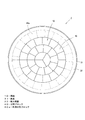
図1は油圧クローラドリル110による残銑10の解体方法を説明するための側面図を示し、図2は炉底部2の平面図を示している。なお、図2における残銑10に一点鎖線で表す分割ラインL(Lc,Lr)は後述する分割ライン設定工程で設定するラインである。
An embodiment of the present invention will be described below with reference to the drawings.
FIG. 1 is a side view for explaining a method of dismantling the
また、図3は残銑の解体工法のフローチャートを示し、図4は穿孔工程完了時の炉底部2の縦断面図を示し、図5は穿孔工程完了時の炉底部2の平面図を示している。なお、図5中のa部についての拡大図については、分割孔20以外の残銑10、つまり穿孔工程で穿孔されなかった残銑10をハッチングで示している。
3 shows a flowchart of the demolition method of the residue, FIG. 4 shows a longitudinal sectional view of the
さらにまた、図6は外周分割ブロック40aの搬出完了時の炉底部2の縦断面図を示し、図7は外周分割ブロック40aの搬出完了時の炉底部2の平面図を示している。
FIG. 6 is a longitudinal sectional view of the
本実施形態で説明する解体工法は、高炉1の炉底部2の耐火底面33上に残留固化した残銑10を、振動や騒音を発生させることなく、安全且つ効率的に解体する工法である。
図1に示す炉底部2は、解体する高炉1の底部であり、最外周側を覆う鉄皮31と、鉄皮31の内側において所定の厚みで形成された円筒状の耐火側壁32と、耐火側壁32の内側において所定の高さ方向の厚みを有する平面視円周状の耐火底面33とで構成し、断面形状凹型に形成している。
The dismantling method described in the present embodiment is a method of dismantling the
The
なお、鉄皮31及び耐火側壁32は、耐火煉瓦を積み上げるとともに、固定して構成している。また、図1では、既に、上方の鉄皮31及び耐火側壁32が撤去された状態を示している。
The
そして、耐火側壁32と耐火底面33とで囲まれた領域において残留固化した残銑10、いわゆるサラマンダは、高温溶融状態であった鉱物が冷却固化したものであり、比重が重く、且つコンクリート構造物等に比べて大幅に高い強度を有している。
また、高温溶融状態であった鉱物が冷却固化した残銑10は、経年的に堆積した不純物を含んでおり、一般的に溶断することも困難である。
The
Further, the
このような残銑10を、振動や騒音を発生させることなく、安全且つ効率的に解体するために、本解体工法では、油圧クローラドリルシステム100を用いる。油圧クローラドリルシステム100は、作業員Mによって操作される操作盤101と、油圧クローラドリル110とで構成され、作業員Mによる操作盤101の操作によって駆動する構成である。
In order to dismantle
油圧クローラドリル110は、本体部111と、本体部111の下方に配置されたクローラ120と、本体部111の前方に配置した油圧ドリル装置130とで構成している。
The
油圧ドリル装置130は、アーム133によって、本体部111に対して所望の角度に調整自在に取り付けられたドリル駆動部132と、ドリル駆動部132の下方先端から回転しながら下方に向かって出し入れ可能なドリル131とで構成している。
The
ドリル131は、平面視十字状の超硬チップ(図示省略)を先端に配置するとともに、適宜の径で形成している。ドリル131の径は、穿孔する対象物の強度に応じて定まるが、高温溶融状態であった鉱物が冷却固化した残銑10を穿孔する本実施形態においては、その径を100mmとしている。
The
油圧クローラドリルシステム100を上述のような構成としているため、クローラ120の回転駆動により、油圧クローラドリル110は、残銑10上を自由に走行することができる。そして、所望の位置まで走行し、ドリル131の位置や穿孔方向を、穿孔位置に対してアーム133により容易に調整することができる。
Since the hydraulic
さらに、穿孔位置に調整されたドリル131を、ドリル駆動部132によって、回転させるとともに、出し入れすることで残銑10を容易に穿孔して分割孔20を形成することができる。
Further, the
例えば、コンクリート構造物等に比べて大幅に高い強度を有している残銑10を穿孔する場合における従来の穿孔方法は、上述したように、ダイヤモンドコアカッタ等を用いた穿孔装置を、カットアンカ等を用いて固定することから始まる。そして、固定された穿孔装置で穿孔する際には、穿孔装置を固定するカットアンカの固定力を反力として、回転するダイヤモンドコアカッタで残銑10を穿孔する。しかし、強度の高い残銑10を穿孔するには、少しずつ穿孔するため穿孔に要する時間が長かった。また、カットアンカの固定力が低いと、残銑10を穿孔する反力によって穿孔装置の固定が解除されるおそれがあった。このように、穿孔に長い時間と多くの手間を要する穿孔装置による穿孔の場合、分割孔20の数が多いと、その時間や手間は莫大となり、施工コストも増大することとなる。
For example, as described above, the conventional drilling method in the case of drilling the remnant 10 having a significantly higher strength than a concrete structure or the like uses a drill anchor using a diamond core cutter or the like as described above. Begin by fixing with etc. When drilling with the fixed drilling device, the
これに対し、油圧クローラドリルシステム100の油圧クローラドリル110で残銑10を穿孔すると、油圧クローラドリル110の重量が重いため、ドリル131を穿孔位置に調整するだけで別途の固定が不要となる。また、油圧クローラドリル110の重量が重く、アーム133によってドリル131を適宜の位置及び方向に調整できるため、油圧クローラドリル110の重量を反力として、効率よくドリル131で残銑10を穿孔し、分割孔20を形成することができる。
On the other hand, when the
次に、このような油圧クローラドリルシステム100を用いた残銑10の解体工法の施工順序について、図3に示すフローチャートともに詳述する。
まず、残銑10の解体に先立って、図1に示すように、炉底部2より上方の鉄皮31及び耐火側壁32を撤去する。
Next, the construction sequence of the demolition method for the
First, prior to dismantling the
そして、解体可能な状態となった残銑10に対して、図2に示すように、分割ラインL(Lc,Lr)を設定する(ステップs1)。
詳しくは、分割ラインLを設定するに当たり、残銑10の厚み、比重及び強度を求め、搬出可能な残銑10の容積を算出する。そして、算出された容積に応じた分割ブロック40(図2)を構成できる分割ラインLを設定する。このとき、残銑10の強度に応じて、分割ラインLに沿って穿孔する分割孔20同士の所定間隔Sを算出するとともに考慮し、分割孔20の数が少なくなるように分割ラインLを設定する。
Then, as shown in FIG. 2, a dividing line L (Lc, Lr) is set for the
Specifically, when setting the dividing line L, the thickness, specific gravity, and strength of the
なお、所定間隔Sは、残銑10の強度に基づき、複数の分割孔20を穿孔した残銑10上を油圧クローラドリル110が走行可能、且つ、所定間隔Sの残銑10をバックホウのバケットの爪等で、振動や騒音を発生させることなく分断して分割ブロック40を容易に形成できる間隔に設定する。本実施形態においては、図2に示すように、3本の径の異なる同心円である周方向分割ラインLcと、中心Cと内側の周方向分割ラインLcあるいは周方向分割ラインLc同士の間を結ぶ、複数本の放射方向のLrを設定している。
The predetermined interval S is based on the strength of the
分割ライン設定工程(ステップs1)で分割ラインLが設定された後、穿孔機である油圧クローラドリルシステム100を残銑10上にセットする(ステップs2)。
After the dividing line L is set in the dividing line setting step (step s1), the hydraulic
そして、クローラ120で残銑10上を走行するとともに、アーム133でドリル131を分割ラインL上の穿孔位置に調整し、ドリル駆動部132を駆動させてドリル131で残銑10を穿孔し、分割孔20を形成する(ステップs3)。このとき、分割孔20同士の間には所定間隔Sの未穿孔連結部21が形成される。これを繰り返し、設定された分割ラインL上の穿孔位置全てを穿孔し、分割孔20を形成する。
なお、この穿孔工程(ステップs3)における穿孔順序は、クローラ120による走行、及びアーム133による位置調整や方向調整が極力少なくなる順序とすることが好ましい。
Then, the
In addition, it is preferable that the drilling order in this drilling step (step s3) is an order in which traveling by the
図4及び図5に示すように、穿孔工程(ステップs3)における分割孔20の穿孔が完了した後、残銑10上から穿孔機である油圧クローラドリルシステム100を退去させ(ステップs4)、その後、残銑10の側方を囲繞していた鉄皮31及び耐火側壁32を、図4に示す撤去ラインTで撤去する(ステップs5)。これで、分割孔20が形成された残銑10の側方は露出し、鉄皮31及び耐火側壁32による残銑10の拘束が解放される。
As shown in FIGS. 4 and 5, after the drilling of the divided
この状態において、分割孔20同士の間の未穿孔連結部21をバックホウのバケットの爪等によって振動や騒音を発生させることなく破壊し、残銑10を分割孔20によって分断して分割ブロック40を形成し(ステップs6)、分割ブロック40を撤去搬出する(ステップs7)。
In this state, the unperforated connecting
なお、分割ブロック分断工程(ステップs6)及び分割ブロック搬出工程(ステップs7)を交互に繰り返して、全数の分割ブロック40を分断及び撤去搬出してもよいが、本実施形態では、図6及び図7に示すように、最外周の分割ブロック40のうちひとつの外周分割ブロック40aをまず分断し、撤去搬出してから、その撤去搬出した外周分割ブロック40aの隣の外周分割ブロック40aを分断し、撤去搬出する。これを繰り返して、まず最外周の外周分割ブロック40aを全部撤去搬出してから、径内側の周方向の分割ブロック40を順次、分断及び撤去搬出する。
The divided block dividing step (step s6) and the divided block unloading step (step s7) may be alternately repeated to divide and remove all the divided blocks 40. In this embodiment, FIG. 6 and FIG. As shown in FIG. 7, one of the outermost divided
このように、同じ周方向の分割ブロック40を順次、ひとつずつ分断及び撤去搬出することにより、撤去搬出された分割ブロック40のスペースが形成されるため、隣の分割ブロック40を容易に分断及び撤去することができる。
In this way, by dividing and removing the divided
このようにして、分割ブロック分断工程(ステップs6)及び分割ブロック搬出工程(ステップs7)を行って、全分割ブロック40を撤去搬出することで残銑10の解体は完了する。なお、残銑10の下側の耐火底面33は、上述したように耐火煉瓦を積み上げて固定して構成しており、また長年の使用により容易に解体することができる。
Thus, the division | segmentation of the
上述したように、残銑10を解体する解体工法として、残銑10を分割する分割ラインLを設定する分割ライン設定工程(ステップs1)と、下向きに穿孔する油圧ドリル装置130を備え、残銑10上を走行可能な油圧クローラドリル110によって、分割ラインLに沿うとともに、所定間隔Sを隔てた複数の分割孔20を、分割ラインLに全体に亘って穿孔する穿孔工程(ステップs3)と、穿孔工程完了後に、残銑10から油圧クローラドリル110を退去させる穿孔機退去工程(ステップs4)と、所定間隔Sを隔てた複数の分割孔20によって分割ラインLで残銑10を分割して分割ブロック40として搬出する分割ブロック搬出工程(ステップs7)とで構成したことにより、発生する騒音や振動を低減できるとともに、安全且つ効率よく残銑10を解体することができる。
As described above, the demolition method for dismantling the
詳しくは、下向きに穿孔する油圧ドリル装置130を備え、残銑10上を走行可能な油圧クローラドリル110によって、前工程の分割ライン設定工程(ステップs1)で設定した分割ラインLに沿うとともに、所定間隔Sを隔てた複数の分割孔20を、効率よく穿孔することができる。
Specifically, the
さらに詳述すると、この穿孔工程(ステップs3)では、下向きに穿孔する油圧ドリル装置130を備え、残銑10上を走行可能な油圧クローラドリル110を用いるため、穿孔速度は速く、また油圧ドリル装置130を固定や移動する時間を省略できるため、効率よく穿孔することができる。
More specifically, in this drilling step (step s3), since the
なお、分割孔20を、所定間隔Sを隔てて穿孔するため、上述の効果に加え、各分割孔20をラップさせて穿孔する場合と比較し、穿孔数を低減できるため、穿孔工程(ステップs3)を短縮化できる。また、穿孔数の低減によって、油圧クローラドリル110の油圧ドリル装置130のドリル131の摩耗も低減できるため、穿孔工程(ステップs3)における工事コストの増大を抑制することができる。
Since the divided
さらに、穿孔工程後(s3)の穿孔機退去工程(ステップs4)では、残銑10から油圧クローラドリル110を退去させる、換言すると、油圧クローラドリル110で全数の分割孔20を穿孔してから油圧クローラドリル110を退去させるが、隣り合う分割孔20同士の間に所定間隔S分の未穿孔連結部21が残るように複数の分割孔20を穿孔するため、穿孔工程完了後(ステップs3)であっても、残銑10上を油圧クローラドリル110が走行することができる。
Further, in the drilling machine leaving step (step s4) after the drilling step (s3), the
つまり、複数の分割孔20を穿孔した後であっても、残銑10上を自由に油圧クローラドリル110が走行できるため、穿孔のために容易に移動して、効率よく油圧クローラドリル110で穿孔することができる。
That is, even after the plurality of divided
さらにまた、穿孔機退去工程後(ステップs4)に、分割孔20同士の間の未穿孔連結部21をバックホウのバケットの爪等で、振動や騒音を発生させることなく、容易に破壊しながら、分割ラインLで残銑10を分割することができる。
Furthermore, after the drilling machine leaving step (step s4), the
したがって、安全且つ効率的に、残銑10をブロック化し、分割ブロック40として容易に搬出することができる。よって、安全、且つ効率よく、すなわち解体工程を短縮化するとともに、解体工事に要する工事コストの増大を防止することができる。
Therefore, the
また、穿孔工程(ステップs3)で全分割孔20を穿孔してから、つまり穿孔工程完了してから、鉄皮等撤去工程(ステップs5)、分割工程(ステップs6)、及び搬出工程(ステップs7)を行うため、油圧クローラドリル110の使用期間が短縮化できるとともに、同じ作業を繰り返すため、段取り替えの回数を低減できるとともに、施工効率を向上することができる。
Further, after all the divided
また、分割ラインLを、平面視内側から外側に向かう内外方向に残銑10を分割する周方向の周方向分割ラインLcと、残銑10を周方向に分割する内外方向の放射方向分割ラインLrとで構成することにより、残銑10を容易に分割して分割ブロック40を構成することができるとともに、分割した分割ブロック40を容易に搬出することができる。
In addition, the dividing line L is divided into a circumferential dividing line Lc in the circumferential direction that divides the
詳しくは、残銑10を周方向分割ラインLcで内外方向に分割するとともに、放射方向分割ラインLrで周方向に分割するため、容易に搬出可能な大きさや重量の分割ブロック40を形成することができる。
Specifically, since the
また、分割ブロック40を形成した後に、周方向の一部の分割ブロック40を撤去搬出することによって、同じ周方向の分割ブロック40をさらに容易に分割して、撤去搬出することができる。したがって、さらに、効率よく残銑10を解体することができる。
Further, after forming the divided blocks 40, by removing and carrying out some of the divided
また、残銑10の外側に配置され、残銑10の側方を囲繞する鉄皮31及び耐火側壁32を撤去する鉄皮等撤去工程(ステップs5)を、穿孔機退去工程(ステップs4)と、分割ブロック搬出工程(ステップs7)との間に行うことにより、穿孔工程(ステップs3)において所定間隔Sを隔てた分割孔20を複数穿孔した場合において、分割孔20が穿孔された残銑10上を油圧クローラドリル110が走行しても、残銑10の側方を鉄皮31及び耐火側壁32が囲繞して拘束しているため、残銑10が崩れたりすることがなく、安全に穿孔機退去工程(ステップs4)で油圧クローラドリル110を残銑10上から退去させることができる。
Further, the
また、解体対象が高炉の耐火底面33上に残留した残銑10であり、残銑10は一般的なコンクリート構造物に比べ強度が高く、例えば、ワイヤーソー等による解体の場合、分割解体には時間もコストもかかる。しかし、上述の解体工法では、油圧クローラドリル110で効率よく残銑10に分割孔20を穿孔し、分割ブロック40を形成して、分割解体することができる。
Further, the object to be demolished is the
また残銑10を分割した分割ブロック40の重量が搬出可能な重量となるように分割ラインLを設定しているため、通常のコンクリートブロック等に比べて比重が高く、例えば、ダンプ等の搬出車両に積載する積載重量を超えやすい残銑10であっても、上述の解体工法では、効率よく、分割孔20を穿孔し、容易に分割ブロック化できるため、安全に搬出可能な分割ブロック40を効率よく構成することができる。
Further, since the dividing line L is set so that the weight of the divided
なお、上述の説明において、平面視円形の残銑10を底版として考え解体対象としたが、一般的なコンクリート構造物である床版を解体する場合であっても、上述の効果を得ることができる。また、解体対象が平面視円形でなくとも、例えば、平面視多角形状であってもよい。この場合、内外方向に残銑10や底版を分割する周方向分割ラインLcは平面視多角形と相似形状とすることができる。
In the above description, the
この発明の構成と、上述の実施形態との対応において、
この発明の床版あるいは残銑は、残銑10に対応し、
以下同様に、
穿孔手段は、油圧ドリル装置130に対応し、
穿孔機は、油圧クローラドリル110に対応し、
分割ブロックは、分割ブロック40,外周分割ブロック40aに対応し、
内外方向分割ラインは、放射方向分割ラインLrに対応し、
側方囲繞部材は、鉄皮31及び耐火側壁32に対応し、
炉底耐火物は、耐火底面33に対応し、
分割ライン設定工程は、ステップs1に対応し、
穿孔工程は、ステップs3に対応し、
穿孔機退去工程は、ステップs4に対応し、
側方囲繞部材撤去工程は、ステップs5に対応し、
分割ブロック搬出工程は、ステップs7に対応するが、
この発明は、上述の実施形態の構成のみに限定されるものではなく、多くの実施の形態を得ることができる。
In correspondence between the configuration of the present invention and the above-described embodiment,
The floor slab or residue of this invention corresponds to the
Similarly,
The drilling means corresponds to the
The drilling machine corresponds to the
The divided blocks correspond to the divided
The inner and outer direction division lines correspond to the radial direction division lines Lr,
The side wall member corresponds to the
The furnace refractory corresponds to the refractory bottom 33,
The dividing line setting process corresponds to step s1,
The drilling process corresponds to step s3,
The drilling machine leaving process corresponds to step s4,
The side gob member removal process corresponds to step s5,
The divided block carry-out process corresponds to step s7,
The present invention is not limited only to the configuration of the above-described embodiment, and many embodiments can be obtained.
例えば、残銑10を解体する上述の説明においては、もともと残銑10の側方を囲繞する鉄皮31や耐火側壁32を残したまま、残銑10を油圧クローラドリル110で穿孔したが、残銑10の側方を囲繞する鉄皮31や耐火側壁32を撤去してから、残銑10を油圧クローラドリル110で穿孔してもよい。この場合、隣り合う分割孔20同士の間の所定間隔Sを、側方を拘束する鉄皮31や耐火側壁32がない状態で、上面を油圧クローラドリル110が走行することを許容する間隔に設定することが好ましい。
For example, in the above description of dismantling the
さらには、コンクリート床版のように、側方を囲繞する部材がない解体対象部材を解体する場合、穿孔工程(ステップs3)より前に、解体対象の側方を囲繞する囲繞部材を新たに設置してから穿孔工程(ステップs3)を行ってもよい。これにより、上述の説明と同様の効果を得ることができる。 Furthermore, when dismantling a member to be dismantled that does not have a member that surrounds the side, such as a concrete floor slab, a surrounding member that surrounds the side to be dismantled is newly installed before the drilling step (step s3). Then, the drilling step (step s3) may be performed. Thereby, the effect similar to the above-mentioned description can be acquired.
10…残銑
20…分割孔
31…鉄皮
32…耐火側壁
33…耐火底面
40…分割ブロック
40a…外周分割ブロック
110…油圧クローラドリル
130…油圧ドリル装置
L…分割ライン
Lc…周方向分割ライン
Lr…放射方向分割ライン
S…所定間隔
DESCRIPTION OF
Claims (5)
前記床版を分割する分割ラインを設定する分割ライン設定工程と、
下向きに穿孔する穿孔手段を備え、前記床版上を走行可能な穿孔機によって、前記分割ラインに沿うとともに、所定間隔を隔てた複数の分割孔を、前記分割ラインに全体に亘って穿孔する穿孔工程と、
穿孔完了後に、前記床版から前記穿孔機を退去させる穿孔機退去工程と、
所定間隔を隔てた複数の前記分割孔によって前記分割ラインで前記床版を分割して分割ブロックとして搬出する分割ブロック搬出工程とで構成する
解体工法。 A demolition method for dismantling the floor slab,
A dividing line setting step for setting a dividing line for dividing the floor slab;
A drilling machine comprising a drilling means for drilling downward and capable of traveling on the floor slab, and drilling a plurality of divided holes along the dividing line and spaced apart by a predetermined interval over the dividing line. Process,
After completion of drilling, a drilling machine leaving step for moving the drilling machine out of the floor slab,
A dismantling method comprising a divided block carrying-out step in which the floor slab is divided along the dividing line by a plurality of the divided holes separated by a predetermined interval and carried out as divided blocks.
平面視内側から外側に向かう内外方向に前記床版を分割する周方向の周方向分割ラインと、
前記床版を前記周方向に分割する前記内外方向の内外方向分割ラインとで構成した
請求項1に記載の解体工法。 The dividing line is
A circumferential circumferential dividing line that divides the floor slab in an inner / outer direction from the inner side to the outer side in plan view;
The dismantling method according to claim 1, wherein the floor slab is constituted by the inner and outer direction dividing lines that divide the slab in the circumferential direction.
前記穿孔機退去工程以降、前記分割ブロック搬出工程以前に行う
請求項1又は2に記載の解体工法。 A side wall member removing step that is disposed outside the floor slab and removes a side wall member that surrounds a side of the floor slab,
The dismantling method according to claim 1 or 2, wherein the dismantling method is performed after the perforating machine leaving step and before the divided block unloading step.
請求項1乃至3のうちいずれかに記載の解体工法。 The demolition method according to any one of claims 1 to 3, wherein the floor slab is a residue left on a bottom refractory of a blast furnace.
請求項1乃至4のうちいずれかに記載の解体工法。 The dismantling method according to any one of claims 1 to 4, wherein the dividing line is set so that a weight of a divided block obtained by dividing the residue becomes a weight that can be carried out.
Priority Applications (1)
| Application Number | Priority Date | Filing Date | Title |
|---|---|---|---|
| JP2011025697A JP2012162787A (en) | 2011-02-09 | 2011-02-09 | Demolition method |
Applications Claiming Priority (1)
| Application Number | Priority Date | Filing Date | Title |
|---|---|---|---|
| JP2011025697A JP2012162787A (en) | 2011-02-09 | 2011-02-09 | Demolition method |
Publications (1)
| Publication Number | Publication Date |
|---|---|
| JP2012162787A true JP2012162787A (en) | 2012-08-30 |
Family
ID=46842453
Family Applications (1)
| Application Number | Title | Priority Date | Filing Date |
|---|---|---|---|
| JP2011025697A Withdrawn JP2012162787A (en) | 2011-02-09 | 2011-02-09 | Demolition method |
Country Status (1)
| Country | Link |
|---|---|
| JP (1) | JP2012162787A (en) |
Cited By (4)
| Publication number | Priority date | Publication date | Assignee | Title |
|---|---|---|---|---|
| JP2014084561A (en) * | 2012-10-19 | 2014-05-12 | Tama Kayaku Kiko Kk | Method for demolishing concrete structure in demolition site with height restricted to about 2.5 m |
| JP2020002386A (en) * | 2018-06-25 | 2020-01-09 | 日本製鉄株式会社 | Method of cutting pig iron in blast furnace |
| JP2020002385A (en) * | 2018-06-25 | 2020-01-09 | 日本製鉄株式会社 | Blast furnace pig iron cutting device and blast furnace pig iron cutting method |
| JP2020002387A (en) * | 2018-06-25 | 2020-01-09 | 日本製鉄株式会社 | Blast furnace pig iron cutting device and pig iron cutting method |
-
2011
- 2011-02-09 JP JP2011025697A patent/JP2012162787A/en not_active Withdrawn
Cited By (6)
| Publication number | Priority date | Publication date | Assignee | Title |
|---|---|---|---|---|
| JP2014084561A (en) * | 2012-10-19 | 2014-05-12 | Tama Kayaku Kiko Kk | Method for demolishing concrete structure in demolition site with height restricted to about 2.5 m |
| JP2020002386A (en) * | 2018-06-25 | 2020-01-09 | 日本製鉄株式会社 | Method of cutting pig iron in blast furnace |
| JP2020002385A (en) * | 2018-06-25 | 2020-01-09 | 日本製鉄株式会社 | Blast furnace pig iron cutting device and blast furnace pig iron cutting method |
| JP2020002387A (en) * | 2018-06-25 | 2020-01-09 | 日本製鉄株式会社 | Blast furnace pig iron cutting device and pig iron cutting method |
| JP7027267B2 (en) | 2018-06-25 | 2022-03-01 | 日本製鉄株式会社 | Pig iron cutting device and pig iron cutting method in a blast furnace |
| JP7027266B2 (en) | 2018-06-25 | 2022-03-01 | 日本製鉄株式会社 | Blast furnace pig iron cutting device and blast furnace pig iron cutting method |
Similar Documents
| Publication | Publication Date | Title |
|---|---|---|
| JP6145306B2 (en) | Pile head processing method | |
| JP2012162787A (en) | Demolition method | |
| JP6186346B2 (en) | How to remove synthetic girder concrete | |
| JP4810475B2 (en) | How to remove blast furnace residue | |
| JP2012162959A (en) | Method for simultaneous ground and underground demolition of existing skeleton | |
| JP5795232B2 (en) | Dismantling method | |
| JP7121596B2 (en) | Dismantling method of mat slab | |
| JP6873718B2 (en) | How to dismantle floor slab members | |
| JP2019167690A (en) | Pile head processing method | |
| JP3977543B2 (en) | How to remove blast furnace residue | |
| JP5162170B2 (en) | How to remove blast furnace residue | |
| JP6707001B2 (en) | Coke oven retaining wall dismantling method | |
| JP4034639B2 (en) | Delineation removal method for lining layer and demolition removal apparatus used therefor | |
| JP6411048B2 (en) | Dismantling method | |
| JP7042626B2 (en) | Turn-turning device | |
| JP6363343B2 (en) | High-rise building demolition method | |
| KR101414550B1 (en) | Method of removing residual pig iron from blast furnace | |
| JP6436733B2 (en) | Demolition method of concrete slab | |
| JP6230414B2 (en) | Existing underground exterior wall removal method and building rebuilding method | |
| WO2015108098A1 (en) | Dismantling method | |
| JP5986512B2 (en) | Dismantling method | |
| JP6692548B2 (en) | Cast iron material processing method and hole formation assisting jig | |
| TW201404989A (en) | Low vibration crushing RC constructional method | |
| JP4182252B2 (en) | Removal device and method for removing lining layer of fire wall | |
| JP2024038887A (en) | Disassembly method |
Legal Events
| Date | Code | Title | Description |
|---|---|---|---|
| A300 | Withdrawal of application because of no request for examination |
Free format text: JAPANESE INTERMEDIATE CODE: A300 Effective date: 20140513 |