JP2012158376A - Container direction regulation system - Google Patents
Container direction regulation system Download PDFInfo
- Publication number
- JP2012158376A JP2012158376A JP2011020640A JP2011020640A JP2012158376A JP 2012158376 A JP2012158376 A JP 2012158376A JP 2011020640 A JP2011020640 A JP 2011020640A JP 2011020640 A JP2011020640 A JP 2011020640A JP 2012158376 A JP2012158376 A JP 2012158376A
- Authority
- JP
- Japan
- Prior art keywords
- container
- gripper
- holding
- grip
- restricting
- Prior art date
- Legal status (The legal status is an assumption and is not a legal conclusion. Google has not performed a legal analysis and makes no representation as to the accuracy of the status listed.)
- Granted
Links
Images


Abstract
Description
本発明は、容器グリッパによって容器のネック部を保持して容器を搬送する容器搬送装置に関する。 The present invention relates to a container transport device that transports a container while holding the neck of the container with a container gripper.
従来、容器搬送装置で断面形状が長方形や楕円形等の異形容器を搬送する際に、容器の方向を一定方向に揃える工夫がなされてきた。(特許文献1) Conventionally, when transporting a deformed container having a cross-sectional shape of a rectangle or an ellipse by a container transport device, the device has been devised to align the direction of the container in a certain direction. (Patent Document 1)
近年、PETボトルのような容器では、容器コスト削減等のために薄肉化の傾向にあり、薄肉容器になると、容器が変形しやすく、断面形状が長方形や楕円形等の異形容器の場合で、容器を一定の方向に揃える際に、従来技術では容器が潰れてしまうことがあるため、容器が潰れないようにする要求が高まっている。また、容器を搬送中に電子線照射して殺菌する電子線殺菌装置においては、電子線照射する容器面を一定の方向とする必要があり、容器の方向規制を確実に行えるようにする要求、また、容器の方向規制に際して容器の表面に傷が付かないようにする要求が出されている。 In recent years, containers such as PET bottles tend to be thin for container cost reduction, etc., and when thin containers are used, the containers are easily deformed, and in the case of a deformed container such as a rectangle or an ellipse, When aligning containers in a certain direction, the container may be crushed in the prior art, and thus there is an increasing demand for preventing the containers from being crushed. In addition, in the electron beam sterilization apparatus that sterilizes by irradiating with an electron beam while transporting the container, the container surface to be irradiated with the electron beam needs to be in a certain direction, and the request to ensure that the direction of the container can be regulated, In addition, there is a demand for preventing the surface of the container from being damaged when regulating the direction of the container.
前記特許文献1によれば、充填機の入口スターホイールの外周に、異形容器の代表寸法に近い直径の軟質材から成る円板状の方向規制ガイドを設けて、該方向規制ガイドに容器を接触させて押し圧力と摩擦力によって容器の方向規制をするとしている。
しかしながら、前記特許文献1の技術では、容器がネック部を保持されたまま前記円板状の方向規制ガイドにより押し付けられるため、容器の方向規制が確実性に欠け、薄肉容器の場合には、容器が傷付き、また、変形回復出来ない程に潰れてしまう恐れがある。
According to
However, in the technique of
本発明は、搬送体に設けられた容器グリッパによって容器のネック部を保持して容器を搬送する容器搬送装置において、断面形状が長方形や楕円形等の異形容器を方向規制する場合に、薄肉容器でも、容器の潰れ、容器の傷付きを発生させずに、確実に容器の方向規制ができる容器方向規制装置を提供することを目的としている。 The present invention relates to a container transport apparatus that transports a container while holding the neck portion of the container by a container gripper provided on the transport body, and in the case of restricting the direction of a deformed container having a rectangular or elliptical cross-sectional shape, the thin container However, an object of the present invention is to provide a container direction regulating device that can reliably regulate the direction of the container without causing the container to be crushed or damaged.
前記の課題に対し、本発明は以下の手段により解決を図る。
(1)第1の手段の容器方向規制装置は、搬送体に設けられた容器グリッパによって容器のネック部を保持して容器を搬送する容器搬送装置において、該容器搬送装置の所定の搬送領域(以下容器方向規制領域と称する)で、容器が前記容器グリッパから落下しないで回転自在な状態になるように前記容器グリッパの容器保持に緩みを持たせるグリップ保持緩み手段と、容器を搬送中に前記グリップ保持緩み手段によって前記回転自在にした状態で方向が一定の向きになるよう方向規制する容器方向規制手段とを設けて、容器を搬送中に方向規制するように構成したことを特徴とする。
The present invention solves the above problems by the following means.
(1) The container direction regulating device of the first means is a container transport device that transports a container while holding the neck portion of the container with a container gripper provided on the transport body. (Hereinafter, referred to as a container direction regulating region), grip holding loosening means for loosening the container holding of the container gripper so that the container does not fall from the container gripper and can be rotated, and Container direction restricting means for restricting the direction so that the direction becomes a fixed direction in the state of being freely rotatable by the grip holding loosening means is provided so as to restrict the direction during transport of the container.
(2)第2の手段の容器方向規制装置は、前記第1の手段の容器方向規制装置において、該容器方向規制装置を、容器の中味が空の状態で容器の方向規制をするようにしたことを特徴とする。 (2) The container direction restricting device of the second means is the container direction restricting device of the first means, wherein the container direction restricting device restricts the direction of the container in a state where the contents of the container are empty. It is characterized by that.
(3)第3の手段の容器方向規制装置は、前記第1および第2の手段の容器方向規制装置において、前記グリップ保持緩み手段を、前記容器方向規制領域で前記容器グリッパのグリッパ開閉機構部がカムと係合するようにして、該カムを前記容器方向規制領域では前記容器グリッパが容器回転自在の状態となるように作用し、前記容器方向規制領域以外では前記容器グリッパが容器保持の状態となるように作用するカム軌跡として構成したことを特徴とする。 (3) The container direction regulating device of the third means is the gripper opening / closing mechanism portion of the container gripper in the container direction regulating region in the container direction regulating device of the first and second means. Is engaged with the cam so that the container gripper can be rotated in the container direction regulating region, and the container gripper is in a state in which the container gripper is held outside the container direction regulating region. It is characterized by being configured as a cam trajectory that acts as follows.
(4)第4の手段の容器方向規制装置は、前記第1および第2の手段の容器方向規制装置において、前記グリップ保持緩み手段を、前記容器方向規制領域で前記容器グリッパのグリッパ開閉機構部が往復動式プッシャーと係合するようにして、該往復動式プッシャーを前記容器方向規制領域では前記容器グリッパが容器回転自在の状態となるように作用し、前記容器方向規制領域以外では前記容器グリッパが容器保持の状態となるように作用する作動制御で構成したことを特徴とする。 (4) The container direction restricting device of the fourth means is the gripper opening / closing mechanism portion of the container gripper in the container direction restricting region in the container direction restricting device of the first and second means. Is engaged with the reciprocating pusher so that the container gripper is in a state in which the container gripper can freely rotate in the container direction restricting region, and the container is disposed outside the container direction restricting region. The gripper is configured by operation control that acts so as to be in a container holding state.
(5)第5の手段の容器方向規制装置は、前記第1から第4の手段の容器方向規制装置において、前記容器方向規制手段を、前記容器方向規制領域で容器が搬送される際に、該容器が所定の方向となっていない場合には、容器が接触して方向修正(方向規制)されるようなガイド形状の容器方向規制ガイドで構成したことを特徴とする。 (5) The container direction restricting device of the fifth means is the container direction restricting device of the first to fourth means, wherein the container direction restricting means is used when the container is transported in the container direction restricting region. When the container is not in a predetermined direction, the container is characterized by a guide-shaped container direction regulation guide that is in contact with the container to correct the direction (direction regulation).
請求項1に係わる本発明は、容器搬送装置の所定の容器方向規制領域で、容器が前記容器グリッパから落下しないで回転自在な状態になるように前記容器グリッパの容器保持に緩みを持たせるグリップ保持緩み手段と、容器を搬送中に前記グリップ保持緩み手段によって前記回転自在にした状態で方向が一定の向きになるよう方向規制する容器方向規制手段とを設けて、容器を搬送中に方向規制するように構成したことにより、方向規制される容器に無理な力が作用することを防止でき、薄肉容器でも、容器方向規制の際に容器の潰れ、容器の傷付きを発生させずに確実に容器を方向規制できるという効果を有する。 According to a first aspect of the present invention, there is provided a grip for loosening a container holding of the container gripper so that the container does not fall from the container gripper and can be rotated in a predetermined container direction regulating region of the container transport device. Holding and loosening means and container direction restriction means for restricting the direction so that the direction becomes a fixed direction while being rotated by the grip holding and loosening means while transporting the container are provided, and the direction is restricted while the container is being transported. It is possible to prevent excessive force from acting on the container whose direction is restricted, and even for thin-walled containers, it is possible to reliably prevent the container from being crushed and damaged. This has the effect that the direction of the container can be restricted.
請求項2に係わる本発明は、前記請求項1に記載する容器方向規制装置において、該容器方向規制装置を、容器の中味が空の状態で容器の方向規制をするようにしたので、容器の方向規制が効率よく容易に行えるという効果を有する。
The present invention according to
請求項3に係わる本発明は、前記請求項1および2に記載する容器方向規制装置において、前記グリップ保持緩み手段を、前記容器方向規制領域で前記容器グリッパのグリッパ開閉機構部がカムと係合するようにして、該カムを前記容器方向規制領域では前記容器グリッパが容器回転自在の状態となるように作用し、前記容器方向規制領域以外では前記容器グリッパが容器保持の状態となるように作用するカム軌跡として構成したことにより、容器の方向規制を簡素な装置で行えるという効果を有する。 According to a third aspect of the present invention, in the container direction regulating device according to the first and second aspects, the grip holding / loosening means is engaged with a gripper opening / closing mechanism portion of the container gripper in the container direction regulating region. Thus, the cam acts so that the container gripper is in a rotatable state in the container direction restricting region, and acts so that the container gripper is in a container holding state outside the container direction restricting region. By configuring as a cam trajectory, it is possible to control the direction of the container with a simple device.
請求項4に係わる本発明は、前記請求項1および2に記載する容器方向規制装置において、前記グリップ保持緩み手段を、前記容器方向規制領域で前記容器グリッパのグリッパ開閉機構部がカムではなくて往復動式プッシャーと係合するようにして、該往復動式プッシャーを前記容器方向規制領域では前記容器グリッパが容器回転自在の状態となるように作用し、前記容器方向規制領域以外では前記容器グリッパが容器保持の状態となるように作用する作動制御で構成したことにより、所謂カム軌跡を変更しなければならない場合において、カムを変更するのではなく、往復動式プッシャーを作動制御する制御装置のプログラム変更のみで容易に変更することができ、また、装置をコンパクトにできるという効果を有する。 According to a fourth aspect of the present invention, in the container direction regulating device according to the first and second aspects, the grip holding / loosening means is configured such that the gripper opening / closing mechanism portion of the container gripper is not a cam in the container direction regulating region. The reciprocating pusher is engaged with the reciprocating pusher so that the container gripper is in a state in which the container gripper can freely rotate in the container direction restricting region. Of the control device for controlling the operation of the reciprocating pusher instead of changing the cam when the so-called cam trajectory has to be changed. It can be easily changed only by changing the program, and the apparatus can be made compact.
請求項5に係わる本発明は、前記請求項1から4に記載する容器方向規制装置において、前記容器方向規制手段を、前記容器方向規制領域で容器が搬送される際に、該容器が所定の方向となっていない場合には、容器が接触して方向修正(方向規制)されるようなガイド形状の容器方向規制ガイドで構成したことにより、容器の方向規制を簡素な装置で効率良く行えるという効果を有する。 According to a fifth aspect of the present invention, in the container direction regulating device according to any one of the first to fourth aspects, when the container is transported in the container direction regulating region, the container is restricted to a predetermined direction. When it is not in the direction, it is possible to efficiently control the direction of the container with a simple device by configuring it with a guide-shaped container direction control guide that is contacted to correct the direction (direction control). Has an effect.
以下、この発明の実施の形態につき図面を参照しつつ詳細に説明する。なお、この実施の形態によりこの発明が限定されるものではない。また、下記実施の形態における構成要素には、当業者が容易に想定できるもの、あるいは実質的に同一のものが含まれる。 Hereinafter, embodiments of the present invention will be described in detail with reference to the drawings. Note that the present invention is not limited to the embodiments. In addition, constituent elements in the following embodiments include those that can be easily assumed by those skilled in the art or those that are substantially the same.
(発明の第1の実施の形態)
本発明の第1の実施の形態を図1から図6に基づいて説明する。
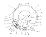
図1は、本発明の第1の実施の形態に係わる容器方向規制装置を取り入れた充填ラインを摸式的に示した平面図である。
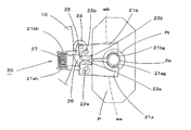
図2は、本発明の第1の実施の形態に係わる容器方向規制装置の平面図で、部分切断図としてある。
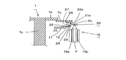
図3は、図2のA−A断面図である。
図4は、図2に示す容器グリッパの詳細平面図で、容器保持の状態を示す図である。
図5は、容器グリッパの図4に相当する図で、グリップ保持緩みを説明する図である。
図6は、容器がスターホイールのポケットに受け渡された状態を説明する図で、(a)は正規方向の容器がスターホイールのポケットに正常に収納された状態を示し、(b)は正規方向でない容器がスターホイールのポケットに押し込まれて潰れた状態を示す図である。
(First Embodiment of the Invention)
A first embodiment of the present invention will be described with reference to FIGS.
FIG. 1 is a plan view schematically showing a filling line incorporating a container direction regulating device according to the first embodiment of the present invention.
FIG. 2 is a plan view of the container direction regulating device according to the first embodiment of the present invention, which is a partially cut view.
FIG. 3 is a cross-sectional view taken along the line AA of FIG.
FIG. 4 is a detailed plan view of the container gripper shown in FIG. 2 and shows a state of holding the container.
FIG. 5 is a view corresponding to FIG. 4 of the container gripper, and is a view for explaining grip holding looseness.
FIG. 6 is a diagram illustrating a state where the container is delivered to the star wheel pocket. FIG. 6A illustrates a state where the container in the normal direction is normally stored in the star wheel pocket, and FIG. It is a figure which shows the state which the container which was not direction pushed into the pocket of the star wheel, and was crushed.
図1において、後述するネック部Pnを有し、胴部の断面形状が異形で長方形(図示は長方形の角部を面取りした形状としている)の容器Pが、上流の矢印F1方向からネック搬送装置C1でネック部Pnを保持されながら搬送されて、図示S点で容器転送装置(容器搬送装置。以下容器搬送装置を称する)1の後述する容器グリッパ20に受け渡され、搬送中に容器方向規制装置15で方向規制された後、矢印1f方向に搬送されて図示T点で充填装置2の図示しない容器グリッパに受け渡され、矢印2f方向の回転搬送中に充填装置2から液体を充填された後、矢印3f方向に回転する容器転送装置3に受け渡され、次いで、容器Pに図示しないキャップを締めるキャッパ4に受け渡され、矢印4f方向の回転中にキャップ締めされた後に、矢印5f方向に回転する容器転送装置5で転送されて、後工程の矢印F2方向へコンベヤC2により搬出されるようになっている。
In FIG. 1, a container P having a neck portion Pn, which will be described later, and having a barrel section having an irregular shape and a rectangular shape (having a shape in which a rectangular corner portion is chamfered) is connected to the neck conveying device from the upstream arrow F1 direction. C1 is conveyed while holding the neck portion Pn, and is transferred to a container gripper 20 (to be described later) of a container transfer apparatus (container conveyance apparatus; hereinafter referred to as a container conveyance apparatus) 1 at a point S in the figure, and the container direction is restricted during conveyance. After the direction is regulated by the
なお、ここでは、容器Pは、ネック搬送装置C1からキャッパ4までは、容器Pのネック部Pnを保持されて搬送され、容器転送装置5ではネック部Pnは保持されずにスターホイール5sのポケット5pに容器Pの胴部を収納され、容器Pの底部を搬送板5b上に載置されながら搬送されるようになっており、さらに、コンベヤC2上では容器Pの底部を載置されながら搬送されるようになっている。
Here, the container P is transported from the neck transport device C1 to the capper 4 while holding the neck portion Pn of the container P, and the
前記容器搬送装置1は、図2および図3に示すように、図示しない駆動装置で回転駆動される回転軸1cに固定された円板1aにドーナッツ形状の円板(搬送体。以下搬送体と称する)1bが固定され、該搬送体1bに容器Pのネック部Pnを保持する容器グリッパ20がブラケット29を介して円周等分に設けられている。
また、前記容器搬送装置1のS点からT点に向けての搬送中間部の容器方向規制領域V1に、容器Pの方向規制をする容器方向規制装置15が設けられている。
As shown in FIGS. 2 and 3, the
In addition, a container
前記容器方向規制装置15は、カム10と前記容器グリッパ20の後述するグリッパ開閉機構部のローラ24との係合によって、前記容器グリッパ20から容器Pが落下しないで回転自在な状態になるように前記容器グリッパ20の容器保持に緩みを持たせるグリップ保持緩み手段と、グリップ保持緩み状態の容器Pの方向規制をする容器方向規制ガイド15aと容器方向規制ガイド15bから成る容器方向規制手段とにより構成されている。
なお、前記容器方向規制ガイド15aと容器方向規制ガイド15bは、図2に示すように、容器方向規制領域V1の入口部では間隔が拡げられる等容器の方向修正に適した形状となっており、それぞれ図示しない固定のブラケットに取付けられている。
また、前記カム10は、容器グリッパ20が前記グリッパ保持緩み状態、容器保持状態になるようなカム軌跡となっており、固定の支持台11に取付けられている。
The container
The container
The
さらに、前記容器搬送装置1には、図示S点で上流から搬送されてくる容器Pのネック部Pnが前記容器グリッパ20に受け渡されるように、後述するグリップアーム21aとグリップアーム21bを開閉させるカム1dが固定の支持台1eに設けられている。同様に、図示T点にも容器Pのネック部Pnが容器搬送装置1から充填装置2へ受け渡されるように、グリップアーム21aとグリップアーム21bを開閉させるカムが設けられているが、重複する内容となるので、図示および詳細説明を省略する。
Further, the
前記容器グリッパ20は、図3、図4および図5に示すように、前記ブラケット29に設けられた図示しない軸受に軸支された1対の軸22aおよび軸22bにそれぞれグリップアーム21aおよびグリップアーム21bが固定されており、該グリップアーム21aおよびグリップアーム21bのグリップ部21agおよびグリップ部21bgが前記1対の軸22aおよび軸22bとともに閉方向に揺動回転することにより、ネック部Pn(容器Pの鍔部Ptの上方)を保持できるようになっているとともに、前記グリップアーム21aおよびグリップアーム21bが、他端のばね受け部21ahおよびばね受け部21bhがばね27によって前記一対の軸22aおよび軸22bの軸心を支点として押し広げられることにより、前記グリップ部21agとグリップ部21bgが閉方向に揺動回転してネック部Pnを保持するようになっている。
As shown in FIGS. 3, 4 and 5, the
さらに、前記グリップアーム21aおよびグリップアーム21bには、互いに噛合う半月状のギヤ23aおよびギヤ23bが取付けられており、レバー26に設けられた軸25の周りを回転するローラ24が前記カム10に係合することによって、前記軸22aに取付けられた前記レバー26の揺動回転に伴い、前記ばね27の作用に抗して前記グリップ部21agとグリップ部21bgを開方向に揺動回転させるグリッパ開閉機構部となっていて、前記カム10のカム軌跡により前記揺動回転量が規制されるようになっている。
Further, the
次に、本発明の第1の実施の形態に係わる容器方向規制装置15の作用を説明する。
なお、図5において、グリップアーム21aおよびグリップアーム21bが実線で示されているのは、容器グリッパ20から容器Pが落下しないで回転自在な状態になるように前記容器グリッパ20の前記グリップ保持に緩みを持たせた状態を示し、二点鎖線で示したグリップアームwaおよびグリップアームwbは、S点およびT点で容器Pの受け渡しをする際にグリッパ開とした状態を示している。
Next, the operation of the container
In FIG. 5, the
容器Pがネック搬送装置C1から容器搬送装置1にS点で受け渡される際、容器グリッパ20は図2に示すS点の手前のR点でローラ24とカム1dとの係合によりグリップアーム21aおよびグリップアーム21bが開の状態となり、S点での受け渡し後、容器グリッパ20はネック部Pnをグリップ保持するように閉の状態となる。
ここでは、容器Pの断面の長手方向が、容器搬送装置1の搬送経路円1pに対して接線方向である状態を正規方向としているが、正規方向から外れて図示P1の二点鎖線のような状態である場合には、容器Pの方向修正、即ち方向規制が必要となる。
When the container P is transferred from the neck conveying device C1 to the
Here, the state in which the longitudinal direction of the cross section of the container P is a tangential direction with respect to the
容器Pは、容器方向規制領域V1部に搬送されてくると、容器グリッパ20の開閉機構部のローラ24がカム10と係合することによって、カム10のカム軌跡により、軸25、レバー26、軸22a、ギヤ23aおよびギヤ23bを介して、グリップアーム21aおよびグリップアーム21bが図5の実線で示す状態となって、グリップ保持緩み状態となる。
ここで、図示のように方向が正規方向から外れた容器P1は、搬送体1bの搬送により矢印1f方向に進むと、容器P1の胴部が1対の容器方向規制ガイド15aおよび容器方向規制ガイド15bに接触して、図示P2のように容器の方向が搬送円1pの接線方向に修正され、容器方向規制がなされる。
なお、容器Pが正規方向である場合には、容器Pは前記容器方向規制ガイド15aおよび容器方向規制ガイド15bに接触することなく搬送される。
When the container P is conveyed to the container direction regulating region V1, the
Here, when the container P1 whose direction deviates from the normal direction as illustrated is advanced in the direction of the
When the container P is in the normal direction, the container P is transported without contacting the container
容器Pが容器方向規制領域V1を通過した後は、前記カム10のカム軌跡により前記グリップアーム21aおよびグリップアーム21bが、図4に示すように、ネック部Pnを保持するようになり、容器Pは、グリップ保持状態で搬送され、T点の手前でグリッパ開となり、T点で充填装置2の図示しない容器グリッパへ正規方向のまま受け渡される。
なお、容器Pがキャッパ4から容器転送装置5に受け渡される際は、容器Pが正規方向でない状態の場合は、図6(b)のPdで示すように、容器Pがスターホイール5sのポケット5pに押し込まれて潰れてしまう恐れがあるが、容器Pが正規方向の場合は、図6(a)に示すように、容器Pが前記ポケット5pに正常に収納されて、潰れ或いは傷付きが生じることはない。
After the container P passes through the container direction regulating region V1, the
When the container P is delivered from the capper 4 to the
なお、前記説明では、容器方向規制装置15を容器搬送装置1に設けた場合を説明したが、この場合には容器Pは充填前の中味が空の状態であるので、容器重量が小さいため、容器方向規制を効率良く確実に行うことができる。
なお、容器方向規制装置を容器転送装置3に設けてもよいが、この場合には容器Pが充填後の中味入り容器で、重量が大きいため、容器方向規制を確実に行うには搬送速度を下げる必要が生じる恐れがある。
In the above description, the case where the container
A container direction regulating device may be provided in the
また、前記説明では、容器方向規制装置15を、円周回転する容器搬送装置1に設けた場合を説明したが、容器方向規制装置を楕円周回転する容器搬送装置に設けてもよく、さらに、容器方向規制装置を直線搬送の容器搬送装置に設けてもよく、本発明による容器方向規制装置を設ける対象の容器搬送装置の形態に限りは無い。
Further, in the above description, the case where the container
(発明の第2の実施の形態)
次に、本発明の第2の実施の形態について図7に基づいて説明する。
図7は、本発明の第2の実施の形態に係わる容器方向規制装置の平面図で、部分切断図としてあり、図2に相当する図である。
図7において、図2と同じ構造のものは同じ記号を付してあり、重複する説明は省略するが、容器搬送装置1tの容器方向規制装置15tは、容器方向規制領域V2部で容器グリッパ20のグリッパ開閉機構部のローラ24と往復動式プッシャー装置30との係合によって、前記容器グリッパ20から容器Pが落下しないで容器回転自在の状態にするグリップ保持緩み手段と、グリップ保持緩み状態の容器Pを方向規制する容器方向規制ガイド15aと容器方向規制ガイド15bから成る容器方向規制手段により構成されている。
(Second Embodiment of the Invention)
Next, a second embodiment of the present invention will be described with reference to FIG.
FIG. 7 is a plan view of a container direction regulating apparatus according to the second embodiment of the present invention, which is a partially cutaway view, and corresponds to FIG.
In FIG. 7, the same structure as that of FIG. 2 is denoted by the same symbol, and overlapping description is omitted. However, the container
前記往復動式プッシャー装置30は、前記ローラ24と係合するプッシャー31がロッド32を介してサーボシリンダ33の作動によって往復動されるようになっており、前記プッシャー31の往復動によりローラ24、軸25、レバー26、軸22a、ギヤ23aおよびギヤ23bを介して前記グリップアーム21aおよびグリップアーム21bが、それぞれ軸22aおよび軸22bを支点として揺動回転することによって、ネック部Pnを保持又は保持緩み、或いは開とするような構成になっている。
なお、前記サーボシリンダ33は、図示しない制御装置からの指令により往復動の移動量および移動速度が作動制御されるようになっており、図示しない固定の支持台に設けられている。
In the
The
前記往復動式プッシャー装置30と同様の往復動式プッシャー装置が、上流のネック搬送装置C1から容器Pが受け渡されるS点近辺にも設けられており、容器Pのネック部Pnを受け渡され、かつ、前記容器グリッパ20のグリップアーム21aおよびグリップアーム21bによりネック部Pnが保持されるようになっている。
さらに、前記説明と同様の往復動式プッシャー装置が、容器Pを充填装置2に受け渡すT点近辺にも設けられているが、重複する内容であり、図示および詳細な説明は省略する。
A reciprocating pusher device similar to the
Further, a reciprocating pusher device similar to the above description is also provided in the vicinity of the point T that delivers the container P to the
次に、本発明の第2の実施の形態に係わる容器方向規制装置15tの作用を説明する。
容器Pがネック搬送装置C1から容器搬送装置1tにS点で受け渡される際、容器グリッパ20はS点の手前のR点で前記プッシャー装置の作動制御によりグリップアーム21aおよびグリップアーム21bが開の状態となり、S点で受け渡された後、容器グリッパ20はネック部Pnを保持するように閉の状態となる。
Next, the operation of the container
When the container P is transferred from the neck conveying device C1 to the
容器Pが方向規制領域V2部に搬送されてくると、容器グリッパ20のグリッパ開閉機構部のローラ24が往復動式プッシャー装置30のプッシャー31と係合することにより、レバー26等を介してグリップアーム21aおよびグリップアーム21bが図5の実線で示す状態となって、グリッパ保持緩み状態となる。
該グリップ保持緩み状態になった容器P1が搬送体1bの搬送により矢印1f方向に進むと、容器P1の胴部が1対の容器方向規制ガイド15aおよび容器方向規制ガイド15bに接触して、図示P2のように容器の方向が搬送円1pの接線方向に修正され、容器方向規制がなされる。
なお、容器Pが正規方向である場合には、容器Pは前記容器方向規制ガイド15aおよび容器方向規制ガイド15bに接触することなく搬送される。
When the container P is conveyed to the direction restricting region V2, the gripper opening / closing mechanism part of the
When the container P1 in the grip holding loose state advances in the direction of the
When the container P is in the normal direction, the container P is transported without contacting the container
容器Pが容器方向規制領域V2を通過した後は、図示しない制御装置からの指令による前記サーボシリンダ33の作動により、前記グリップアーム21aおよびグリップアーム21bが、図4に示すように、ネック部Pnを保持するようになり、容器Pは、グリップ保持状態で搬送され、T点の前方でグリッパ開となり、T点で充填装置2の図示しない容器グリッパへ正規方向のまま受け渡される。
After the container P passes through the container direction regulating region V2, the
前記本発明の第1の実施の形態では、前記グリップ保持緩みを容器グリッパのグリップ開閉機構部とカムとの係合によって行っているため、カム軌跡を変更したい場合にカムを変更しなければならないが、本発明の第2の実施の形態は、前記グリップ保持緩みを容器グリッパのグリップ開閉機構部と往復動式プッシャーとの係合によって行っているため、所謂カム軌跡を変更しなければならない場合において、カムを変更することなく、往復動式プッシャーを作動制御する制御装置のプログラム変更のみで容易に変更することができ、また、装置をコンパクトにできる。 In the first embodiment of the present invention, since the grip holding / loosening is performed by engaging the grip opening / closing mechanism portion of the container gripper with the cam, the cam must be changed when it is desired to change the cam locus. However, in the second embodiment of the present invention, since the grip holding looseness is performed by the engagement of the grip opening / closing mechanism portion of the container gripper and the reciprocating pusher, the so-called cam trajectory must be changed. Therefore, it is possible to easily change the program by changing only the program of the control device for controlling the operation of the reciprocating pusher without changing the cam, and the device can be made compact.
1、1t 容器搬送装置(容器転送装置)
2 充填装置
3 容器転送装置
4 キャッパ
5 容器転送装置
10 カム
15、15t 容器方向規制装置
15a、15b 容器方向規制ガイド
20 容器グリッパ
21a、21b グリップアーム
22a、22b 軸
23a、23b ギヤ
24 ローラ
26 レバー
30 往復動式プッシャー装置
31 プッシャー
33 サーボシリンダ
P 容器
Pn (容器Pの)ネック部
1, 1t Container transfer device (container transfer device)
2 Filling
Claims (5)
Priority Applications (1)
| Application Number | Priority Date | Filing Date | Title |
|---|---|---|---|
| JP2011020640A JP5638410B2 (en) | 2011-02-02 | 2011-02-02 | Container direction control device |
Applications Claiming Priority (1)
| Application Number | Priority Date | Filing Date | Title |
|---|---|---|---|
| JP2011020640A JP5638410B2 (en) | 2011-02-02 | 2011-02-02 | Container direction control device |
Publications (2)
| Publication Number | Publication Date |
|---|---|
| JP2012158376A true JP2012158376A (en) | 2012-08-23 |
| JP5638410B2 JP5638410B2 (en) | 2014-12-10 |
Family
ID=46839246
Family Applications (1)
| Application Number | Title | Priority Date | Filing Date |
|---|---|---|---|
| JP2011020640A Active JP5638410B2 (en) | 2011-02-02 | 2011-02-02 | Container direction control device |
Country Status (1)
| Country | Link |
|---|---|
| JP (1) | JP5638410B2 (en) |
Cited By (1)
| Publication number | Priority date | Publication date | Assignee | Title |
|---|---|---|---|---|
| CN112850624A (en) * | 2021-02-20 | 2021-05-28 | 陈冬梅 | Novel pharmacy department quantitative drenching device |
Citations (2)
| Publication number | Priority date | Publication date | Assignee | Title |
|---|---|---|---|---|
| JP2003276838A (en) * | 2002-03-20 | 2003-10-02 | Japan Crown Cork Co Ltd | Bottle conveying device |
| JP2009073598A (en) * | 2007-09-19 | 2009-04-09 | Mitsubishi Heavy Industries Food & Packaging Machinery Co Ltd | Direction correcting device for non-regular shaped container |
-
2011
- 2011-02-02 JP JP2011020640A patent/JP5638410B2/en active Active
Patent Citations (2)
| Publication number | Priority date | Publication date | Assignee | Title |
|---|---|---|---|---|
| JP2003276838A (en) * | 2002-03-20 | 2003-10-02 | Japan Crown Cork Co Ltd | Bottle conveying device |
| JP2009073598A (en) * | 2007-09-19 | 2009-04-09 | Mitsubishi Heavy Industries Food & Packaging Machinery Co Ltd | Direction correcting device for non-regular shaped container |
Cited By (2)
| Publication number | Priority date | Publication date | Assignee | Title |
|---|---|---|---|---|
| CN112850624A (en) * | 2021-02-20 | 2021-05-28 | 陈冬梅 | Novel pharmacy department quantitative drenching device |
| CN112850624B (en) * | 2021-02-20 | 2022-06-21 | 南京汉尔斯生物科技有限公司 | Novel pharmacy department quantitative drenching device |
Also Published As
| Publication number | Publication date |
|---|---|
| JP5638410B2 (en) | 2014-12-10 |
Similar Documents
| Publication | Publication Date | Title |
|---|---|---|
| EP2844562B1 (en) | Asymmetric article handling and orientation | |
| US8701865B2 (en) | Unscrambling machine for containers and relative process | |
| JP2019513633A (en) | Device for processing containers and beverage filling system | |
| JP6637889B2 (en) | Apparatus and method for transporting carton blanks from a magazine to a carrier | |
| JP2005324966A (en) | Delivery device of packing body | |
| US8668074B2 (en) | Method for transferring an article | |
| CN204661297U (en) | The device of transport box in beverage filling plant | |
| JP3390326B2 (en) | Rotary goods transfer device | |
| JP5638410B2 (en) | Container direction control device | |
| JP2006312492A (en) | Product casing apparatus | |
| JP2003276838A (en) | Bottle conveying device | |
| JP7252440B2 (en) | container carrier | |
| JP6599915B2 (en) | Blister sheet conveying device | |
| JP5709643B2 (en) | Container transfer device | |
| US11046470B2 (en) | Packaging system | |
| JP2005029225A (en) | Bottle gripping apparatus | |
| JP6350075B2 (en) | Resin bottle transfer processing system | |
| JP3978096B2 (en) | Gripper pair, bottle container transfer device | |
| JP6933796B2 (en) | Container transport device | |
| JP6753056B2 (en) | Container alignment and transfer device | |
| JP6207954B2 (en) | Container transfer system | |
| JP6241596B2 (en) | Capper | |
| JP2023081055A (en) | Container processing apparatus | |
| JP3600305B2 (en) | Container cap supply device | |
| CN106395715A (en) | Machine for filling containers |
Legal Events
| Date | Code | Title | Description |
|---|---|---|---|
| A625 | Written request for application examination (by other person) |
Free format text: JAPANESE INTERMEDIATE CODE: A625 Effective date: 20130802 |
|
| A977 | Report on retrieval |
Free format text: JAPANESE INTERMEDIATE CODE: A971007 Effective date: 20140306 |
|
| A131 | Notification of reasons for refusal |
Free format text: JAPANESE INTERMEDIATE CODE: A131 Effective date: 20140401 |
|
| A521 | Written amendment |
Free format text: JAPANESE INTERMEDIATE CODE: A523 Effective date: 20140512 |
|
| A521 | Written amendment |
Free format text: JAPANESE INTERMEDIATE CODE: A821 Effective date: 20140513 |
|
| TRDD | Decision of grant or rejection written | ||
| A01 | Written decision to grant a patent or to grant a registration (utility model) |
Free format text: JAPANESE INTERMEDIATE CODE: A01 Effective date: 20140924 |
|
| A61 | First payment of annual fees (during grant procedure) |
Free format text: JAPANESE INTERMEDIATE CODE: A61 Effective date: 20141022 |
|
| R150 | Certificate of patent or registration of utility model |
Ref document number: 5638410 Country of ref document: JP Free format text: JAPANESE INTERMEDIATE CODE: R150 |
|
| S111 | Request for change of ownership or part of ownership |
Free format text: JAPANESE INTERMEDIATE CODE: R313111 |
|
| R350 | Written notification of registration of transfer |
Free format text: JAPANESE INTERMEDIATE CODE: R350 |
|
| R250 | Receipt of annual fees |
Free format text: JAPANESE INTERMEDIATE CODE: R250 |
|
| S531 | Written request for registration of change of domicile |
Free format text: JAPANESE INTERMEDIATE CODE: R313531 |
|
| S533 | Written request for registration of change of name |
Free format text: JAPANESE INTERMEDIATE CODE: R313533 |
|
| R350 | Written notification of registration of transfer |
Free format text: JAPANESE INTERMEDIATE CODE: R350 |