JP2012158317A - Handle fixing device for bicycle - Google Patents
Handle fixing device for bicycle Download PDFInfo
- Publication number
- JP2012158317A JP2012158317A JP2011035152A JP2011035152A JP2012158317A JP 2012158317 A JP2012158317 A JP 2012158317A JP 2011035152 A JP2011035152 A JP 2011035152A JP 2011035152 A JP2011035152 A JP 2011035152A JP 2012158317 A JP2012158317 A JP 2012158317A
- Authority
- JP
- Japan
- Prior art keywords
- handle
- fixing device
- bicycle
- support base
- handle fixing
- Prior art date
- Legal status (The legal status is an assumption and is not a legal conclusion. Google has not performed a legal analysis and makes no representation as to the accuracy of the status listed.)
- Pending
Links
- 238000001125 extrusion Methods 0.000 claims 1
- 238000003466 welding Methods 0.000 abstract 1
- 210000001061 forehead Anatomy 0.000 description 2
- 230000000694 effects Effects 0.000 description 1
- 230000000149 penetrating effect Effects 0.000 description 1
Images

Landscapes
- Steering Devices For Bicycles And Motorcycles (AREA)
Abstract
Description
本発明は自転車の駐停車後にハンドルが反転して起きる転倒とそれによる破損を防止し、減少させる物に関する。The present invention relates to an object that prevents and reduces a fall caused by turning a steering wheel after a bicycle is parked and stopped, and damage caused thereby.
従来、自転車を駐停車させるとその接地面や風圧の状況と前篭の荷物の加減などによりハンドル(前輪共)が一方に反転し、転倒することが多かった。転倒により、左右の物や車両に接触して物損事故を起こしていた。Conventionally, when a bicycle is parked or parked, the steering wheel (both front wheels) has been reversed to one side due to the ground contact surface, wind pressure, and the amount of front luggage, etc., and often falls. Due to the fall, he was in contact with left and right objects and vehicles, causing a property damage accident.
以上に述べた自転車の駐停車後のハンドルの反転を無くし、それを固定する事にある。本発明は以上の問題を解決する為に成されたものである。This is to eliminate the reversal of the steering wheel after the bicycle is parked and stopped and to fix it. The present invention has been made to solve the above problems.
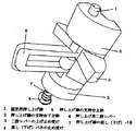
1 ハンドルステム側のハンドルパイプ前方の前篭受け(ステー)に下方から押し上がる押し出し棒を受け通す孔を開ける。
2 前篭受けに開けた孔を突き通す押し出し棒を支える支持台を作成する。
3 押し出し棒にそれを上下させて停止させる二股形のレバーを設ける。
4 二股レバーを停止させて留める止め受けを支持台に設ける。
5 支持台の下方に押し出し棒を押し戻す(下げる)バネを設ける。
6 作成した支持台の一体をヘッドチューブ(車台フレームの)前面に溶接して取り付ける。
この押し出し棒がハンドルステムに固定している前篭受けの孔に突き通る事でハンドルの動きが固定される。1 Open a hole through which the push-out bar that pushes up from below is placed in the front saddle support (stay) in front of the handle pipe on the handle stem side.
2 Create a support that supports the push-out bar that penetrates the hole in the forehead.
3. Provide a bifurcated lever that stops the push bar up and down.
4 Provide a support on the support base to stop and fasten the bifurcated lever.
5 Provide a spring that pushes back (lowers) the push bar below the support.
6 Weld the built support base to the front of the head tube (chassis frame).
The movement of the handle is fixed by the push rod penetrating through the hole in the front saddle receiving member fixed to the handle stem.
以上の様に作成した本発明を採用する事で、スタンドの片脚、両脚式を問わず、車体の駐停車後の反転による転倒が格別に減少する。それに比例して、それらの破損状況も減少する。By adopting the present invention created as described above, the fall due to the inversion of the vehicle body after parking and stopping regardless of whether it is a single leg or both legs is significantly reduced. In proportion to this, their damage situation is also reduced.
以下、本発明の実施の形態を図1〜図9に基づいて説明する。
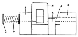
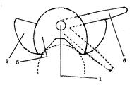
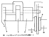
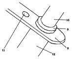
1 ハンドルステム側のハンドルパイプ(図7)(10)前方の前篭受け(ステー)(8)の中央線上に下方から押し上がる押し出し棒(図1)(1)を受け通す円形を前後に伸ばした形の孔(図7)(図9)(11)を開ける。
2 前篭受け(ステー)に開けた孔を突き通す押し出し棒(円柱状)を(図1)(図2)(図3)に示す支持台の上部と下方部によって支える構造にする。
3 この押し出し棒の中央部にこれを上辺と下方への押し上げと引き戻しをする二股形のレバー(取手)(図1)(6)を取り付ける。
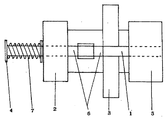
4 支持台上部の下辺の下方に二股レバーの片脚の横幅の長さの間隔(図2)(図3)を置けて、二股レバーの上げ止め受け(図1)(3)を図の様に支持台の左右に設ける。(レバーの上げ止め受けは同時にその下げ止めを果たす)
5 レバーの上げ止め受けの厚さ(幅)を二股レバーの内股間隔(図2)(図3)と同じにする。(支持台上部の下辺からレバーの止め受け(厚さ)の下辺迄の間隔が押し上げ棒の押し上がる長さである)
(二股レバーの両幅の長さとレバーの止め受けの下辺から支持台下方部の上辺迄の間隔が同じである)尚、夫々の間隔に多少の余裕を持たす。
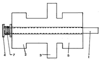
6 レバーと押し上げ棒を下げ戻す為のコイル状の戻しバネ(図2)(図3)(図4)(7)を支持台下方端に突き出している棒の部分に図の様に通し、そのコイルバネを留める円盤形の止め受け(4)を棒の端に固着する。
本発明は以上の構成よりなる。
以下、上記構成の動作を説明する。
1 特徴として、このハンドル固定装置を図の様に乗る人の勝手(得手)に従い、ヘッドチューブ左右の一方にレバーを向け廻して操作が可能。
2 固定作動させる順序とその解除。
イ 前輪を直方向にし、片方の手でハンドルを少し左右に振りながら、もう片方の手指で二股レバーを上限まで押上げる。この動作により、前篭受け(ステー)の孔に押し上げ棒の先を突き通す。
ロ 押し上げたレバーをそのまま手前に止まるまで引く。
ハ 解除するにはレバーを上限に押し気味に、その止め受けの端沿いを越すまで前方に押し出して手指を放す。それに因り戻し(下げ)バネが働いて解除される。
この戻し(下げ)バネの働きにより、走行中の上下振動による押し出し棒の突き出しは無い。突き出さないため、ハンドルの固定もそれに因る事故も起きない。
3 追記、前篭を付ける場合、事前に得手の側にレバーを向け廻して置く。
本発明主要部の取り付けは、その支持台上部上辺をヘッドチューブ上端の縁に接して行う。Hereinafter, embodiments of the present invention will be described with reference to FIGS.
1. Handle pipe on the handle stem side (Fig. 7) (10) Push rod (Fig. 1) (1) that pushes up from the bottom on the center line of the front saddle receiver (stay) (8) in front. Open a hole (Fig. 7) (Fig. 9) (11).
(2) A push rod (columnar shape) that penetrates a hole drilled in a forehead support (stay) is supported by an upper part and a lower part of a support base shown in (FIG. 1) (FIG. 2) (FIG. 3).
3 Attach a bifurcated lever (handle) (FIG. 1) (6) that pushes and pulls the push bar upward and downward at the center of the push bar.
4 Place the gap of the width of one leg of the bifurcated lever (Fig. 2) (Fig. 3) below the lower side of the upper part of the support base, and raise the bifurcated lever (Fig. 1) (3) as shown in the figure. On the left and right sides of the support base. (The lever's lifting stopper receives its lowering at the same time.)
5 The thickness (width) of the lever raising stopper receiver is the same as the inner crotch interval (FIG. 2) (FIG. 3) of the bifurcated lever. (The distance from the lower side of the upper part of the support base to the lower side of the lever stopper (thickness) is the length that the push-up bar is pushed up)
(The length of both widths of the bifurcated lever is the same as the distance from the lower side of the lever receiving stopper to the upper side of the lower part of the support base.) Note that there is some margin in each interval.
6 Pass the coil-like return spring (Fig. 2) (Fig. 3) (Fig. 4) (7) through the bar protruding from the lower end of the support base as shown in the figure. A disk-shaped stopper (4) for fastening the coil spring is fixed to the end of the bar.
The present invention has the above configuration.
The operation of the above configuration will be described below.
1 As a feature, this handle fixing device can be operated by turning the lever to either the left or right of the head tube according to the hand of the person who rides as shown in the figure.
2 The order of fixed operation and its release.
B) With the front wheel in a straight direction, swing the handle slightly to the left and right with one hand and push the bifurcated lever up to the upper limit with the other finger. By this operation, the tip of the push-up bar is pierced through the hole of the front saddle receiver (stay).
B Pull the pushed-up lever until it stops.
C To release, push the lever to the upper limit and push it forward until it passes along the edge of the catch and release your finger. Therefore, the return (lowering) spring works and is released.
Due to the action of the return (lowering) spring, there is no protrusion of the push rod due to vertical vibration during traveling. Because it does not stick out, there is no problem with the fixing of the handle or the accident.
3 When adding a postscript or an outpost, place the lever facing the player in advance.
The main part of the present invention is attached with the upper upper side of the support base in contact with the upper edge of the head tube.
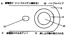
1 固定用押し上げ棒 7 押し上げ棒の戻し(下げ)バネ
2 押し上げ棒の支持台下方部 8 前篭受け(ハンドルステム側付き)
3 二股レバーの上げ止め受け 9 前篭受けの止めナット
4 戻し(下げ)バネの止め受け 10 ハンドルパイプ
5 押し上げ棒の支持台上部 11 押し上げ棒の受け入れ孔
6 押し上げ用二股レバー 12 ヘッドチューブ(ハンドルステム受け)1 Push-up rod for fixing 7 Push-up rod return (lowering) spring 2 Lower support portion of the push-up
3 Lifting stopper receiver for bifurcated
Claims (4)
Priority Applications (1)
| Application Number | Priority Date | Filing Date | Title |
|---|---|---|---|
| JP2011035152A JP2012158317A (en) | 2011-02-01 | 2011-02-01 | Handle fixing device for bicycle |
Applications Claiming Priority (1)
| Application Number | Priority Date | Filing Date | Title |
|---|---|---|---|
| JP2011035152A JP2012158317A (en) | 2011-02-01 | 2011-02-01 | Handle fixing device for bicycle |
Publications (1)
| Publication Number | Publication Date |
|---|---|
| JP2012158317A true JP2012158317A (en) | 2012-08-23 |
Family
ID=46839199
Family Applications (1)
| Application Number | Title | Priority Date | Filing Date |
|---|---|---|---|
| JP2011035152A Pending JP2012158317A (en) | 2011-02-01 | 2011-02-01 | Handle fixing device for bicycle |
Country Status (1)
| Country | Link |
|---|---|
| JP (1) | JP2012158317A (en) |
-
2011
- 2011-02-01 JP JP2011035152A patent/JP2012158317A/en active Pending
Similar Documents
| Publication | Publication Date | Title |
|---|---|---|
| JP2012158317A (en) | Handle fixing device for bicycle | |
| WO2012048297A3 (en) | Stroller with a receiving frame and support straps for receiving a car seat | |
| CN104325906A (en) | Combined structure device of child safety seat and child carriage | |
| JP2014177198A (en) | Bicycle storage apparatus structure | |
| JP3172778U (en) | Moving light folding bike | |
| US1599786A (en) | Golf-bag support | |
| FR2977559B1 (en) | MOTOR VEHICLE WITH TWO WHEELS AND A CARRIER AND PROTECTIVE STRUCTURE | |
| CN201501435U (en) | a safety steering wheel | |
| JP3183383U (en) | Bicycle with fall prevention function | |
| JP2005271743A (en) | Auxiliary wheel for practicing monocycle riding | |
| ES2319846B1 (en) | TAPE COLLECTION REEL. | |
| CN202413487U (en) | Fixing hook structure below child seat | |
| CN103770871A (en) | Rearview mirror of bicycle | |
| JP5844292B2 (en) | 3-point seat belt device | |
| US8998233B2 (en) | Multi-use vehicle assembly | |
| CN201124852Y (en) | Children toy car | |
| JP4345068B2 (en) | High and low simple fluctuation saddle | |
| CN203372266U (en) | Part loading cart | |
| TWI570003B (en) | All terrain car seat structure | |
| JP3158536U (en) | Three-seater bicycle front seat lowering structure | |
| TH134291A (en) | Vehicle seat | |
| JP3054804U (en) | Bicycle alignment bicycle parking and fall prevention equipment | |
| JP2015186931A5 (en) | ||
| JP3202644U (en) | Golf bag simple carrying device | |
| US20140015236A1 (en) | Golf club head cover holder for motorized golf carts |