JP2012157435A - Sphygmomanometer - Google Patents
Sphygmomanometer Download PDFInfo
- Publication number
- JP2012157435A JP2012157435A JP2011017890A JP2011017890A JP2012157435A JP 2012157435 A JP2012157435 A JP 2012157435A JP 2011017890 A JP2011017890 A JP 2011017890A JP 2011017890 A JP2011017890 A JP 2011017890A JP 2012157435 A JP2012157435 A JP 2012157435A
- Authority
- JP
- Japan
- Prior art keywords
- blood pressure
- pressure measurement
- measurement
- sphygmomanometer
- pulse
- Prior art date
- Legal status (The legal status is an assumption and is not a legal conclusion. Google has not performed a legal analysis and makes no representation as to the accuracy of the status listed.)
- Pending
Links
Images


Landscapes
- Measuring Pulse, Heart Rate, Blood Pressure Or Blood Flow (AREA)
- Measurement Of The Respiration, Hearing Ability, Form, And Blood Characteristics Of Living Organisms (AREA)
Abstract
Description
本発明は、腕部などに装着する血圧計に関し、特に血圧測定前の被測定者の身体の情報を合わせて記録できる血圧計に関する。 The present invention relates to a sphygmomanometer worn on an arm or the like, and more particularly to a sphygmomanometer that can record information on the body of a measurement subject before blood pressure measurement.
以前は家庭内での血圧測定は、あまり厳密な測定結果が要求されておらず、日常体調管理の一環としてその測定結果を管理する程度で良く、厳密な測定結果は要求されていなかった。
また、正しく血圧を測定するという行為も重要視されてはいなかったため、測定した血圧値が正しい測定の下に得られた値かどうかを議論することもなかった。
In the past, blood pressure measurement at home did not require a very precise measurement result, and it was sufficient to manage the measurement result as part of daily physical condition management, and a precise measurement result was not required.
Also, since the act of measuring blood pressure correctly was not emphasized, it was not discussed whether the measured blood pressure value was obtained under the correct measurement.
近年は、日常体調管理の重要性が見直されており、最近の報告では、24時間自由行動下で複数回血圧値を測定することがよいとされている。
24時間に複数回血圧値を測定すれば、任意のタイミングで測定する通常の家庭内血圧測定では得られない血圧値の変動を知り得ることができる。つまり、血圧値を単発測定ではなく複数回測定で知れば、血圧値の変動に関係する被測定者の疾病などが見つけやすくなるという考え方である。
In recent years, the importance of daily physical condition management has been reviewed, and a recent report suggests that blood pressure values should be measured multiple times under 24-hour free action.
If the blood pressure value is measured a plurality of times in 24 hours, it is possible to know the fluctuation of the blood pressure value that cannot be obtained by the normal home blood pressure measurement that is measured at an arbitrary timing. In other words, it is an idea that if the blood pressure value is known not by a single measurement but by a plurality of measurements, it is easier to find a disease of the measurement subject related to fluctuations in the blood pressure value.
例えば、通常、夜間や睡眠中は血圧が低下するが、高血圧症の中にはそれが起きない人がいると言われている。また、夜間に血圧が上昇する人もいる。このような人の場合、本来は血管に負担がかからない夜間や睡眠中にも関わらず負担がかかり続けているため、心筋梗塞や脳梗塞などが発症しやすいといわれている。
このように、一日のなかでの血圧値の変動を知ることで、高血圧症のみならず、高血圧が関係するといわれている他の疾病も検知するきっかけとすることができる。
For example, it is usually said that there are people whose blood pressure decreases at night and during sleep, but some do not have it in hypertension. Some people have increased blood pressure at night. Such a person is said to be susceptible to myocardial infarction, cerebral infarction, and the like because it continues to be burdened at night and during sleep, where originally blood vessels are not burdened.
In this way, knowing the fluctuation of the blood pressure value during the day can be a trigger for detecting not only hypertension but also other diseases that are said to be related to high blood pressure.
近年、仮面高血圧、職場高血圧、白衣高血圧などという言葉が知られている。
仮面高血圧とは、正常な血圧であるという仮面をつけた高血圧という意味であり、実際は高血圧であるのに、血圧を測定するときには低い血圧値を示してしまうというものである。
In recent years, words such as masked hypertension, workplace hypertension, and white coat hypertension are known.
Masked hypertension means high blood pressure with a mask indicating that the blood pressure is normal, and actually shows high blood pressure but shows a low blood pressure value when measuring blood pressure.
職場高血圧は、仮面高血圧に属するものである。例えば、被測定者が仕事などで肉体的に疲労していたり、精神的にストレスを受けて高血圧症になっているのであるが、家庭内や病院又は職場の健康診断などでは疲労やストレス要因から解放されるので、リラックス状態となり、そのときに測定した血圧値は低い値を示してしまうというものである。
白衣高血圧とは、家庭内で測定する血圧は正常なのに、病院で測定する血圧は高くなるというものである。
Workplace hypertension belongs to masked hypertension. For example, the person being measured is physically fatigued at work, or is mentally stressed and has high blood pressure. However, due to fatigue or stress factors at home, hospital or workplace health checkups, etc. Since it is released, it becomes a relaxed state, and the blood pressure value measured at that time shows a low value.
White coat hypertension is that blood pressure measured at home is normal, but blood pressure measured at a hospital is high.
白衣高血圧は、病院という環境に身を置くことや白衣を目視することで引き起こされるものであるから、被測定者自身も比較的認識しやすいといわれているが、仮面高血圧及び職場高血圧は、実際には高血圧症であるにも関わらず測定した数値にそれが反映されないため、被測定者はもとより医師などもそれを認識しにくいという問題がある。 White blood pressure hypertension is caused by being placed in a hospital environment or by looking at a white coat, so it is said that the subject itself is relatively easy to recognize. However, it has a problem that it is difficult for a doctor or the like to recognize it because the measured value is not reflected in the measured value in spite of hypertension.
このような、被測定者自身も認識しにくいような症状も、一日のなかでの血圧値の変動を知ることができれば、発見されやすくなる。 Such a symptom that is difficult to be recognized by the person to be measured can be easily found if the fluctuation of the blood pressure value during the day can be known.
このように、日常体調管理の一環として血圧測定の重要性が高まってきているため、正しく血圧測定する行為も重要視されはじめた。 Thus, since the importance of blood pressure measurement has increased as part of daily physical condition management, the act of measuring blood pressure correctly has also started to be emphasized.
正しい血圧測定を実施するためには、2つの条件を満たす必要がある。1つは、被測定者自身が正しい血圧測定を行う状態にあることである。もう1つは、血圧計自体を正しく運用することである。 In order to perform correct blood pressure measurement, two conditions must be satisfied. One is that the person under measurement is in a state of performing correct blood pressure measurement. The other is to properly operate the sphygmomanometer itself.
まず、被測定者自身が正しい血圧測定を行う状態にあることについて説明する。
一般的な考え方として、肉体的緊張や精神的緊張状態にあると、血管が収縮してしまうため、見かけ上、高い血圧値となってしまう。これでは被測定者自身が正しく血圧値を測定する状態にあるとはいえない。
このため、血圧測定時には、緊張状態から開放して臨むことが大切であり、例えば、深呼吸をしてから測定に臨むことや、数分前からリラックスした姿勢で待つなどを推奨する場合が多い。
First, it will be described that the person to be measured is in a state of performing correct blood pressure measurement.
As a general way of thinking, blood pressure contracts when the body is in physical or mental tension, resulting in an apparently high blood pressure value. Thus, it cannot be said that the person to be measured is in a state of correctly measuring the blood pressure value.
For this reason, when measuring blood pressure, it is important to open from a tense state. For example, it is often recommended to take a deep breath and then start measuring, or wait in a relaxed posture for several minutes.
つまり、血圧測定は、緊張を解きノンストレス(リラックスしているなど、ストレスが掛かっていない)状態で臨むのが好ましく、こうすれば被測定者自身が正しい血圧測定を行うための1つ目の条件が満たされたといえる。 In other words, it is preferable that the blood pressure measurement be performed in a non-stressed state (relaxed or unstressed) in order to release the tension. It can be said that the condition was satisfied.
ところで、このように測定した血圧値を基底血圧値と呼ぶ。この基底血圧値は、被測定者本来の血圧値であると言ってよい。
日常体調管理の一環として血圧値を管理するためには、この基底血圧値を測定する必要があるが、被測定者がノンストレス状態にあるか否かを調べること、換言すると、被測定者の肉体的安静状態や精神的安定状態を把握することは、とても難しい。被測定者自身がリラックスしているつもりでも、実際はそうではなく、肉体的緊張や精神的緊張状態であるからである。
By the way, the blood pressure value measured in this way is called a basal blood pressure value. It can be said that this basal blood pressure value is a blood pressure value inherent to the measurement subject.
In order to manage blood pressure as part of daily physical condition management, it is necessary to measure this basal blood pressure, but it is necessary to examine whether the subject is in a non-stress state, in other words, the subject's It is very difficult to grasp physical rest and mental stability. This is because, even if the subject himself intends to be relaxed, it is actually not physical tension or mental tension.
このような被測定者の状態を、脈や呼吸を測定することで予想することが知られている。
例えば、脈拍数が高ければストレスを感じているとし、脈拍数が低ければノンストレスとするものである。また、呼吸の周期を測定し、その周波数が高ければストレスを感じているものとする。あるいは、呼吸の数を測定し、その呼吸数が多くなるとストレスを感じているとするものである。
It is known to predict such a state of a person to be measured by measuring a pulse or a respiration.
For example, if the pulse rate is high, the stress is felt, and if the pulse rate is low, the stress is non-stressed. Also, it is assumed that the respiratory cycle is measured and if the frequency is high, the person feels stress. Alternatively, the number of breaths is measured, and stress is felt when the number of breaths increases.
具体的に、脈や呼吸を用いてストレス状態を推測する方法は次のようなものがある。
例えば、睡眠中又は入眠直前の脈拍数や呼吸数を測定しておき、これを基底脈拍数や基底呼吸数として記録し、血圧測定直前に再び脈拍数や呼吸数を測定し、その数値を比べるという方法である。こうすれば、その数値が一定以上多ければ、ストレス状態にあるということがわかる。ただし、呼吸は、被測定者が意識することでその数値を変えることができるため、確度の点では劣っている。そこで、脈を用いて被測定者の肉体的や精神的状態を予想することが多い。
Specifically, there are the following methods for estimating the stress state using the pulse and respiration.
For example, measure the pulse rate or respiratory rate during sleep or just before going to sleep, record this as the basal pulse rate or basal respiratory rate, measure the pulse rate or respiratory rate again immediately before blood pressure measurement, and compare the values It is a method. In this way, if the numerical value is larger than a certain value, it is understood that the stress state is present. However, breathing is inferior in terms of accuracy because the numerical value can be changed by the subject being aware of it. Therefore, the physical and mental state of the measurement subject is often predicted using the pulse.
上述のように、脈や呼吸を用いてストレス状態を推測する方法は、血圧測定前に脈や呼吸を測定しなければならないため、手間が掛かる。
そこで、電子血圧計の場合、血圧測定と同時に脈拍数も測定することができるものもある。このようにすれば、1回の測定行為で済むため便利である。
As described above, the method of estimating the stress state using the pulse and respiration requires time and labor since the pulse and respiration must be measured before blood pressure measurement.
Therefore, some electronic blood pressure monitors can measure the pulse rate simultaneously with the blood pressure measurement. This is convenient because only one measurement action is required.
次に、血圧計自体を正しく運用することについて説明する。
血圧計を正しく運用するには、カフなどの血圧測定部を正しく身体の被測定部位に装着することはもちろんであるが、それに加えて、血圧を測定する部位と心臓との位置関係を適正位置にするということも重要である。適正位置とは、被測定部位と心臓とが同一の高さとなる位置をいう。
Next, correct operation of the blood pressure monitor itself will be described.
In order to operate the sphygmomanometer correctly, the cuff and other blood pressure measuring units must be correctly attached to the body part to be measured, but in addition, the positional relationship between the blood pressure part and the heart is set to the proper position. It is also important to make it. The proper position means a position where the measurement site and the heart are at the same height.
血圧を測定する部位が適性位置にないと、その部位の血管の状態が変わり、正しい血圧が測定できない。
心臓よりも被測定部位が低い位置にあると、血圧が高く測定されてしまうことがある。例えば、心臓よりも被測定部位が10cm下がると、血圧は7mmHg上がると言われている。
If the site for measuring blood pressure is not in the proper position, the state of blood vessels at that site will change and correct blood pressure cannot be measured.
If the site to be measured is lower than the heart, the blood pressure may be measured higher. For example, it is said that the blood pressure increases by 7 mmHg when the measurement site falls 10 cm below the heart.
すなわち、被測定者が適正位置で血圧測定する状態が、血圧計自体を正しく運用するということなのである。こうすれば被測定者自身が正しい血圧測定を行うための2つ目の条件が満たされたといえる。 That is, the state in which the person to be measured measures blood pressure at an appropriate position means that the sphygmomanometer itself is correctly operated. In this way, it can be said that the second condition for the person to be measured to perform correct blood pressure measurement is satisfied.
なお、この適正位置は、心臓と被測定部位との相対高さ位置が適正範囲にあるという意味を含んでいる。適正範囲とは、心臓と被測定部位とがほぼ同じ高さであるという意味を含んでおり、血圧を測定する部位と心臓との位置関係を適正位置にするということは、厳密に寸分の狂いもなく心臓と被測定部位とが同じ高さでなければならないという意味ではない。 This proper position includes the meaning that the relative height position between the heart and the measurement site is in the proper range. The appropriate range includes the meaning that the heart and the measurement site are approximately the same height, and that the positional relationship between the blood pressure measurement site and the heart is in the proper position is strictly inaccurate. It does not mean that the heart and the measurement site must be at the same height.
ところで、近年では、その被測定部位は上腕部がよいと言われている。
その理由は、そもそも上腕部にカフなどを装着しやすいという点と共に、臥位、つまり寝た姿勢でも被測定部位と心臓とが同じ高さにしやすいという点とがあるからである。
By the way, in recent years, it has been said that the measurement site is preferably the upper arm.
The reason is that, in the first place, it is easy to wear a cuff or the like on the upper arm, and it is easy to make the measurement site and the heart to be at the same height even in a lying position, that is, in a sleeping position.
以上のように、正しい血圧測定を実施するためには、被測定者自身がノンストレス状態にあることと、血圧計自体が適正位置で測定されていることとの2つが揃わなければならないが、電子血圧計にあっては、それぞれを別個に解決する技術が知られている。
例えば、血圧測定前に被測定者をリラックス状態にするようにし、その後に血圧測定を開始する技術が知られている(例えば、特許文献1参照。)。
また、被測定部位を手首とし、血圧計本体又は血圧測定部にセンサを搭載して、被測定部位の位置を計測することにより、適正位置で血圧測定ができるようにする技術が知られている(例えば、特許文献2参照。)。
As described above, in order to perform correct blood pressure measurement, the measurement subject himself / herself must be in a non-stress state and the blood pressure monitor itself must be measured at an appropriate position. In the electronic blood pressure monitor, a technique for solving each separately is known.
For example, a technique is known in which a person to be measured is put in a relaxed state before blood pressure measurement and blood pressure measurement is started thereafter (see, for example, Patent Document 1).
Further, a technique is known in which a blood pressure measurement can be performed at an appropriate position by measuring the position of the measurement site by mounting the sensor on the blood pressure monitor main body or the blood pressure measurement unit using the measurement site as a wrist. (For example, refer to Patent Document 2).
特許文献1に示した従来技術は、カフ本体20の内部に呼吸信号検出手段40(エア圧検出センサ)を搭載しており、カフ本体20を被測定部位に装着し、加圧した状態で被測定者の呼吸を測定する。そして、測定した呼吸情報を用いて被測定者の安静状態を判断する。
The prior art disclosed in
しかし、この技術は、カフ本体20に呼吸信号検出手段40を搭載しているため、カフを捲いて加圧した状態でしか呼吸を測定することできない。つまり、血圧測定前に被測定者の状態を知るときに、加圧するというストレスを掛けた状態でしか測定できない。 However, in this technique, since the respiratory signal detection means 40 is mounted on the cuff body 20, respiration can be measured only in a state where the cuff is pressed and pressurized. That is, when knowing the state of the person to be measured before blood pressure measurement, measurement can be performed only in a state where stress is applied.
すでに説明したように、血圧測定時はリラックスして臨むのが好ましく、緊張状態であると血管が収縮し、正しい血圧が測定できない。特許文献1に示した従来技術は、カフ本体20による拘束があるため、被測定者は少なからずストレスが掛かっている。これでは、被測定者の肉体的安静状態や精神的安定状態を正しく知ることはできず、その状態で測定
した血圧値は、被測定者の基底血圧値であるかが分からないという問題がある。
As already explained, it is preferable to take a relaxed approach when measuring blood pressure, and if it is in tension, the blood vessels contract and correct blood pressure cannot be measured. In the conventional technique shown in
すでに説明したように、呼吸の検出をカフ本体20に搭載した呼吸信号検出手段40で行なっているが、腕部に装着したカフ本体20では、正確に呼吸を検出することは難しい。呼吸を検出するには、呼吸動作に伴う体動や二酸化炭素排出量などを用いることが知られているが、腕部ではそれらを正確に知る得ることは難しい。 As described above, the respiration is detected by the respiration signal detection means 40 mounted on the cuff body 20, but it is difficult to accurately detect respiration with the cuff body 20 attached to the arm. In order to detect respiration, it is known to use body movements and carbon dioxide excretion accompanying respiration, but it is difficult to accurately know them in the arm.
さらにまた、特許文献1に示した従来技術は、呼吸信号検出手段40を椅子やベッドなどに設置することや身体に間接的に装着することを示唆している。
しかし、具体的な技術内容は開示されておらず、どのような仕組みを用いてどのように間接的に呼吸を計測するか不明である。つまり、思想が紹介されているだけであって、技術が完成しているとはいえない。
Furthermore, the prior art shown in
However, specific technical contents are not disclosed, and it is unclear how to measure respiration indirectly using what mechanism. In other words, the idea is only introduced and the technology is not complete.
特許文献2に示した従来技術は、傾斜センサを用いて心臓の高さを測定する方式であり、間接的に心臓の位置を類推する。
しかし、このため、測定精度が悪く、測定結果への信頼性が低く、また肘からの角度で規定するため測定姿勢が変則的になって、適正位置に合わせ難いという問題がある。
The prior art shown in
However, there is a problem that the measurement accuracy is poor, the reliability of the measurement result is low, and the measurement posture is irregular because it is defined by the angle from the elbow, and it is difficult to adjust to the proper position.
また、特許文献2に示した従来技術は、心音センサを用いて心臓位置を測定する方式も開示している。身体の心臓部付近に心音センサを内蔵した手首装着式血圧計を近接させて、直接心臓の位置を探っていく方式である。
しかし、心音の検出にマイクロホンを使用しているため、被測定者は服を脱ぎ胸を露出する必要がある。着衣のまま血圧測定ができないことは大変不便である。
さらに、心音センサは、外部の大きな音響雑音の影響を受けやすく、検出感度が低下して、心臓の位置に対応するピーク値の検出が不安定になるという問題もある。
The prior art disclosed in
However, since the microphone is used to detect the heart sound, the person to be measured needs to undress and expose the chest. It is very inconvenient that blood pressure cannot be measured while wearing clothes.
Furthermore, the heart sound sensor is susceptible to large external acoustic noise, and there is a problem that detection sensitivity is lowered and detection of a peak value corresponding to the position of the heart becomes unstable.
本発明の目的は、上記従来の問題を解決し、血圧測定前の被測定者の肉体的安静状態や精神的安定状態を正しく知ることができ、正しい血圧測定が行える血圧計を提供することにある。また、正確な心臓位置も検出できるから、信頼性の高い血圧測定が行える。 An object of the present invention is to provide a sphygmomanometer that solves the above-described conventional problems, can correctly know the physical rest state and mental stability state of a subject before blood pressure measurement, and can perform correct blood pressure measurement. is there. In addition, since an accurate heart position can be detected, blood pressure can be measured with high reliability.
上記課題を解決するため、本発明の血圧計は下記記載の構成を採用する。 In order to solve the above problems, the sphygmomanometer of the present invention employs the following configuration.
被測定者の測定部位を拘束することにより血圧を測定する血圧計において、
マイクロ波発生器とマイクロ波受信器とを備え、マイクロ波発生器より被測定者にマイクロ波を照射し、マイクロ波受信器により検出されるドップラシフトした反射波から、被測定者の脈拍、呼吸の少なくとも1つを検出し、この検出結果を基に拘束を開始する時期を決定し、血圧を測定することを特徴とする。
In a sphygmomanometer that measures blood pressure by restraining the measurement site of the subject,
A microwave generator and a microwave receiver are provided, and the subject is irradiated with microwaves from the microwave generator, and the pulse and respiration of the subject are measured from the Doppler-shifted reflected waves detected by the microwave receiver. It is characterized in that at least one of the above is detected, the timing for starting restraint is determined based on the detection result, and the blood pressure is measured.
このような構成とすれば、マイクロ波は衣服を透過する性質があり、主に多量の血液を含む心臓に反射されるので、着衣のままでも脈拍、呼吸、体動が検出できる。
そうすれば、直前の被測定者の脈拍や呼吸を調べることができ、その後に血圧測定を開始することができる。
With such a configuration, the microwave has the property of transmitting through clothes and is mainly reflected by the heart containing a large amount of blood, so that the pulse, respiration, and body movement can be detected even while wearing clothes.
If it does so, the pulse and respiration of the measurement subject immediately before can be investigated, and blood pressure measurement can be started after that.
拘束を開始する時期の決定は、所定時間内の脈拍及び呼吸の数である脈拍数、呼吸数の少なくとも1つが所定の範囲内のときに行うようにしてもよい。 The timing for starting restraint may be determined when at least one of the pulse rate and the respiration rate, which is the number of pulses and respirations within a predetermined time, is within a predetermined range.
このような構成にすれば、脈拍と呼吸を理解しやすい数値にでき、その数値に基づいて血圧を測定するときを決定できる。 With such a configuration, it is possible to make the pulse and respiration values easy to understand, and it is possible to determine when to measure the blood pressure based on the values.
脈拍数又は呼吸数を血圧の値に対応させて記憶するメモリ手段を備えるようにしてもよい。 You may make it provide the memory means which memorize | stores a pulse rate or a respiration rate corresponding to the value of a blood pressure.
このような構成にすれば、後からその情報を用いることができるので便利である。 Such a configuration is convenient because the information can be used later.
測定部位と被測定者の心臓との相対高さ位置が適正範囲となる適正位置を検出する適正位置検出手段を備え、拘束を開始する時期の決定は、脈拍数又は呼吸数と適正位置とを用いて行うようにしてもよい。 Providing appropriate position detecting means for detecting an appropriate position in which the relative height position of the measurement site and the heart of the person to be measured is within an appropriate range, and determining when to start restraint is based on the pulse rate or respiratory rate and the appropriate position. May be used.
このような構成にすれば、正しい血圧測定ができる。 With such a configuration, correct blood pressure measurement can be performed.
適正位置検出手段は、被験者の脈拍又は呼吸を用いて検出するようにしてもよい。 The appropriate position detection means may detect the pulse using the pulse or breath of the subject.
マイクロ波受信器により検出されるドップラシフトした反射波を用いて脈拍や呼吸が検出できるので、このようにすれば、体の状態を調べる手段と適性位置を調べる手段とを共通化できるので、装置の小型化、測定の簡便化などができる。 Since the pulse and respiration can be detected using the Doppler-shifted reflected wave detected by the microwave receiver, this makes it possible to share the means for examining the body state and the means for examining the appropriate position. Can be reduced in size and measurement can be simplified.
本発明の血圧計によれば、被測定者の精神的安定状態又は肉体的安静状態を正しく知ることができ、その状態となってから血圧測定することができるから、正しい血圧測定ができる。 According to the sphygmomanometer of the present invention, it is possible to correctly know the mentally stable state or the physical resting state of the measurement subject, and blood pressure can be measured after reaching that state, so that the correct blood pressure can be measured.
また、ドップラシフトした反射波を検出するので、被測定部位と心臓との位置も知ることができる。これにより適正位置で血圧測定できるから、信頼性の高い血圧測定を行うことができる。 Moreover, since the Doppler-shifted reflected wave is detected, the position of the measurement site and the heart can also be known. As a result, blood pressure can be measured at an appropriate position, so that highly reliable blood pressure measurement can be performed.
本発明の血圧計は、マイクロ波ドップラセンサを用いて、被測定者の身体にマイクロ波を照射し、その反射波を受信することで、非接触かつストレスなく被測定者の脈拍、呼吸を測定し、その結果を用いて、被測定者の精神的安定状態又は肉体的安静状態を知る。 The sphygmomanometer of the present invention uses a microwave Doppler sensor to irradiate the subject's body with microwaves and receive the reflected waves, thereby measuring the subject's pulse and respiration without contact and without stress. Then, using the result, the mentally stable state or the physical rest state of the measurement subject is known.
被測定者の身体で反射したマイクロ波の反射波には、脈拍、呼吸、体動が混入している。脈拍、呼吸、体動は、固有の周波数成分を有している。一般に脈拍に関わる周波数よりも呼吸に関わる周波数の方が低い。このような傾向もあるから、マイクロ波ドップラセンサから得られる信号をフーリエ変換した周波数成分の分布からピーク値を選択する周波数閾値範囲を、脈拍や呼吸を検出するようにそれぞれ設定することで、脈拍と呼吸とを計測できる。 Pulses, breaths, and body movements are mixed in the reflected wave of the microwave reflected from the body of the measurement subject. Pulse, respiration, and body movement have unique frequency components. In general, the frequency related to breathing is lower than the frequency related to pulse. Because of this tendency, by setting the frequency threshold range for selecting the peak value from the distribution of frequency components obtained by Fourier transforming the signal obtained from the microwave Doppler sensor so as to detect the pulse and respiration, And breathing.
体動は、被験者の体が痙攣などを起こしていなければ、一般的にはその周波数は低く、周波数分布のピーク値も低いため、脈拍や呼吸と容易に見分けることができる。
脈拍や呼吸は、所定時間内(例えば1分間)の脈拍及び呼吸の数である脈拍数、呼吸数として認識すれば、ストレス状態かノンストレス状態かなどを知ることができ、つまり被測定者の状態を知り得ることができる。
If the subject's body does not have convulsions or the like, the frequency is generally low and the peak value of the frequency distribution is also low, so that it can be easily distinguished from pulse and respiration.
If the pulse and respiration are recognized as the pulse rate and the respiration rate within a predetermined time (for example, 1 minute), it is possible to know whether it is a stress state or a non-stress state. You can know the condition.
そして、反射波から検出できる脈拍、呼吸、体動のうち、脈拍及び呼吸を検出できるということを用いて、血圧測定における血圧計の適正位置を検出することができる。
つまり、血圧計の血圧測定部からマイクロ波を身体に照射しつつこれを動かし、心臓との高さを一致させて適正位置を探すとき、反射波に含まれる脈拍又は呼吸による信号の強弱により、血圧測定部が適正位置に達したかが分かるのである。これにより、適正位置での血圧測定ができることから、さらに信頼性の高い血圧値を得ることができるのである。
And the proper position of the sphygmomanometer in blood pressure measurement can be detected by using the fact that pulse and respiration can be detected among the pulse, respiration, and body motion that can be detected from the reflected wave.
In other words, when moving the body while irradiating the body with microwaves from the blood pressure measurement unit of the sphygmomanometer and searching for an appropriate position by matching the height with the heart, due to the strength of the signal due to the pulse or respiration contained in the reflected wave, It can be seen whether the blood pressure measurement unit has reached the proper position. Thereby, since the blood pressure can be measured at an appropriate position, a more reliable blood pressure value can be obtained.
このような、被測定者自身の状態の測定と血圧計自体の適正位置の測定とには、照射したマイクロ波の反射波を用いるという共通項目があるから、被測定者の精神的安定状態又は肉体的安静状態の検出と、血圧測定における血圧計の適正位置の検出とを、1つの信号処理で行なうことができる。 Since there is a common item that the reflected wave of the irradiated microwave is used for the measurement of the condition of the subject himself and the measurement of the appropriate position of the sphygmomanometer itself, the mental stability state of the subject or The detection of the physical rest state and the detection of the appropriate position of the sphygmomanometer in the blood pressure measurement can be performed by one signal processing.
このようにマイクロ波ドップラセンサを用いることで、非接触で被測定者にとってストレスを受けないことに加え、着衣状態でも測定できるというメリットを有するが、さらに、測定した被測定者の脈拍や呼吸を血圧計の適正位置検出にも用いることができるのである。
そうすれば、被測定者の脈拍や呼吸を別々に測定する手段を備える必要がなくなり、血圧計自体を小型にすることができると共に、測定時間も短縮することができる。
By using the microwave Doppler sensor in this way, in addition to being non-contact and not subject to stress, it has the merit of being able to measure even while wearing clothes, but furthermore, the measured patient's pulse and breathing can be measured. It can also be used to detect the proper position of the sphygmomanometer.
By doing so, it is not necessary to provide means for separately measuring the pulse and respiration of the measurement subject, and the sphygmomanometer itself can be reduced in size and the measurement time can be shortened.
血圧計は、血圧測定開始時に血圧計を装着した部位、例えば手首が身体のどの位置(腕を下げているのか、持ち上げているのかなど)が分からない。その状態から、血圧計を適正位置に移動させるとき、マイクロ波ドップラセンサから得られる信号を処理し、第1の移動検出手段は、その信号が所定の値を超える飽和振幅の回数で大きな腕部の移動状態を検出する。第2の移動検出手段は、フーリエ変換した周波数成分分布の基本波(ピーク値)が所定の周波数閾値範囲に入っているか否か(脈拍や呼吸が正常に検出されたか否か)で適正位置に血圧計があるか否かを検出する。 The sphygmomanometer does not know which part of the body where the sphygmomanometer is worn at the start of blood pressure measurement, such as the wrist (whether the arm is lowered or lifted). When the sphygmomanometer is moved to an appropriate position from that state, the signal obtained from the microwave Doppler sensor is processed, and the first movement detecting means has a large arm portion with the number of saturation amplitudes that the signal exceeds a predetermined value. Detects the moving state of. The second movement detection means is positioned at an appropriate position depending on whether or not the fundamental wave (peak value) of the frequency component distribution subjected to Fourier transform is within a predetermined frequency threshold range (whether pulse or respiration is normally detected). Detect whether there is a sphygmomanometer.
第2の移動検出手段が処理する信号は、マイクロ波ドップラセンサから得られる信号であるから、脈拍や呼吸や体動が混入している。この信号をフーリエ変換処理することで、それぞれの周波数成分が分かる。それを用いて、体動を除く脈拍又は呼吸を用いて被測定者の精神的安定状態又は肉体的安静状態を調べるのである。 Since the signal processed by the second movement detection means is a signal obtained from the microwave Doppler sensor, pulse, respiration, and body movement are mixed. Each frequency component can be obtained by subjecting this signal to Fourier transform processing. Using this, the mental stability state or physical resting state of the measurement subject is examined using the pulse or breathing excluding body movement.
そして、メモリ手段を備えて、脈拍数や呼吸数を、血圧測定を行なったときの時刻情報と対応させて記録することで、血圧測定に臨むとき(つまり血圧測定直前)の被測定者の状態をより詳しく記録することができる。血圧計が適正位置になったことも合わせて記録すれば、後からでも血圧測定が適正に行なわれたことと、そのときの被測定者の状態とを知り得ることができるのである。 Then, a memory means is provided to record the pulse rate and respiratory rate in correspondence with the time information when blood pressure measurement is performed, so that the state of the subject under measurement when blood pressure measurement is started (that is, immediately before blood pressure measurement) Can be recorded in more detail. If it is also recorded that the sphygmomanometer is in the proper position, it is possible to know that the blood pressure measurement has been properly performed and the state of the subject at that time.
第2の移動検出手段は、被測定者の脈拍数や呼吸数を検出するが、後述する第1の実施形態では、脈拍数のみを検出する例を、第2の実施形態では、脈拍数に加えて呼吸数も検出する例を説明する。 The second movement detection means detects the pulse rate and respiration rate of the person to be measured. In the first embodiment to be described later, an example in which only the pulse rate is detected, in the second embodiment, the pulse rate is detected. In addition, an example of detecting the respiratory rate will be described.
このように、血圧値に加えて被測定者の状態も記録できるので、例えば、24時間自由行動下での複数回の血圧測定による血圧値の変化を調べるときであっても、被測定者の肉
体的安静状態や精神的な安定状態の変化が知り得ることができ、正しい血圧測定ができるのである。
Thus, since the state of the subject can be recorded in addition to the blood pressure value, for example, even when examining changes in the blood pressure value due to multiple blood pressure measurements under 24-hour free action, Changes in physical rest and mental stability can be known, and blood pressure can be measured correctly.
本発明の血圧計は、被測定者の脈拍や呼吸を測定し、その結果からストレス状態かノンストレス状態かといった被測定者の状態を知り得ることができる。そのための仕組みのひとつである脈拍や呼吸の検出は、マイクロ波ドップラセンサを用いて行う。このため、脈拍や呼吸の検出結果を血圧計の血圧測定部と心臓との高さを一致させる適正位置の発見にも用いることができる。
適正位置検出を省略することができることは無論であるが、以下説明する実施の形態では、ストレス状態の検出と適正位置検出とを行う場合を例にして説明する。
The sphygmomanometer of the present invention measures the pulse and respiration of the measurement subject and can know the measurement subject's state such as a stress state or a non-stress state from the result. Detection of pulse and respiration, which is one of the mechanisms, is performed using a microwave Doppler sensor. For this reason, the detection result of the pulse or respiration can be used for finding an appropriate position where the height of the blood pressure measurement unit of the sphygmomanometer matches the height of the heart.
Of course, it is possible to omit the proper position detection. However, in the embodiment described below, a case where stress state detection and proper position detection are performed will be described as an example.
以下、本発明の血圧計を図面を用いて詳述する。
血圧計そのものは、血圧を測定するカフなどを有する血圧測定部と制御回路や報知手段などを搭載した血圧計本体とが別体であっても、知られている手首装着式血圧計のようなカフと血圧計本体とが一体となるようなものであっても構わない。以下の説明にあっては、カフと血圧計本体とが一体となる構成を例にして説明する。
Hereinafter, the blood pressure monitor of the present invention will be described in detail with reference to the drawings.
Even if the sphygmomanometer itself is a separate sphygmomanometer with a cuff for measuring blood pressure and a sphygmomanometer body equipped with a control circuit, a notification means, etc. The cuff and the sphygmomanometer body may be integrated. In the following description, a configuration in which the cuff and the sphygmomanometer body are integrated will be described as an example.
以下、図1から図6を用いて本発明の血圧計の第1の実施形態を詳述する。第1の実施形態の特徴は、被測定者の脈拍数を検出することで被測定者の状態を調べるものである。
なお、説明においては、血圧計を主に左手首に装着した場合を例に説明を行う。
Hereinafter, the first embodiment of the sphygmomanometer of the present invention will be described in detail with reference to FIGS. 1 to 6. A feature of the first embodiment is that the state of the subject is examined by detecting the pulse rate of the subject.
In the description, a case where the blood pressure monitor is mainly mounted on the left wrist will be described as an example.
[本発明の原理的説明:図1]
初めに、どのような仕組みでマイクロ波ドップラセンサによって、脈拍や呼吸や体動を検出できるか、そして、どのようにして血圧計と被測定者の心臓とが適正位置にあるかが検出できるかについて詳述する。図1は、血圧計の原理を説明するため模式的に示すブロック図である。
[Principle description of the present invention: FIG. 1]
First, how the microwave Doppler sensor can detect the pulse, respiration, and body movement, and how the sphygmomanometer and the heart of the person being measured are in the proper positions Will be described in detail. FIG. 1 is a block diagram schematically showing the principle of a sphygmomanometer.
図1において、マイクロ波ドップラセンサ21は、例えば、約2.5GHzのマイクロ波を発射するマイクロ波発信器211と、照射したマイクロ波を受信するマイクロ波受信器212と、マイクロ波ドップラ復調器213とで構成されている。
In FIG. 1, a
マイクロ波ドップラセンサは、一般的なマイクロ波ドップラセンサを用いることができる。マイクロ波ドップラセンサには、その出力信号がアナログ信号のものとデジタル信号のものとがあるが、本実施形態では、図1に示すように、マイクロ波ドップラ復調器213からの信号はアナログ信号であり、マイクロ波ドップラセンサ21にはアナログ信号をデジタル信号に変換するAD変換器を搭載していない例で説明をする。
As the microwave Doppler sensor, a general microwave Doppler sensor can be used. The microwave Doppler sensor has an output signal of an analog signal and a digital signal. In this embodiment, as shown in FIG. 1, the signal from the microwave Doppler demodulator 213 is an analog signal. There will be described an example in which the
マイクロ波発信器211から発射されたマイクロ波Meは一部が被測定者8の中に入り、心臓81で反射して反射波Mtとなって再び被測定者8を経由してマイクロ波受信器212で受信される。
マイクロ波発信器211は、発信したマイクロ波Meに相当する電気信号である送信マイクロ波信号Emeを出力し、マイクロ波受信器212は、受信した反射波Mtに相当する電気信号である受信マイクロ波信号Emtを出力する。
A part of the microwave Me emitted from the
The
マイクロ波ドップラ復調器213は、送信マイクロ波信号Emeと受信マイクロ波信号Emtとから、2つの信号の位相差信号である電気信号を、電気信号Eoとして出力する。 The microwave Doppler demodulator 213 outputs an electric signal, which is a phase difference signal between the two signals, from the transmission microwave signal Eme and the reception microwave signal Emt as an electric signal Eo.
すなわち、電気信号Eoには心臓の動きに対応したドップラシフトが生じているので、
このドップラシフトから心臓の動きを電気信号に変換することが可能となるのである。
That is, since the electrical signal Eo has a Doppler shift corresponding to the movement of the heart,
It is possible to convert the heart motion from this Doppler shift into an electrical signal.
もちろん、電気信号Eoには、心臓の動きだけに対応したドップラシフトが生じているわけではない。脈拍、呼吸、体動の要素が混じっている。しかしこれらは、すでに説明したように固有の周波数成分を有しているから、後述するフーリエ変換を用いた手法により、周波数成分の分布からピーク値を選択する周波数閾値範囲を、脈拍や呼吸に合わせることでこれらを検出することができる(体動を脈拍や呼吸と分かつことができる。)。 Of course, the electrical signal Eo does not have a Doppler shift corresponding to only the heart motion. The elements of pulse, breathing and body movement are mixed. However, since these have specific frequency components as described above, the frequency threshold range for selecting the peak value from the distribution of the frequency components is adjusted to the pulse and respiration by the method using the Fourier transform described later. These can be detected (body motion can be separated from pulse and breathing).
[血圧計の移動状態の説明:図2]
次に、適正位置に血圧計を移動する移動状態を図2を用いて説明する。
すでに説明したように、血圧計は、被測定者の精神的安定状態又は肉体的安静状態を正しく知ることと、血圧測定開始時に血圧計を装着した部位が適正位置にあるか否かということとを1つの信号処理で調べることができるから、まずマイクロ波ドップラセンサと被測定者の心臓とを接近させる必要がある。そのために、血圧計を移動させるのである。
[Description of moving state of blood pressure monitor: FIG. 2]
Next, a movement state in which the sphygmomanometer is moved to an appropriate position will be described with reference to FIG.
As already explained, the sphygmomanometer correctly knows the subject's mentally stable state or physical rest state, and whether or not the site where the sphygmomanometer is worn at the start of blood pressure measurement is in the proper position. Therefore, it is necessary to first bring the microwave Doppler sensor close to the measurement subject's heart. For this purpose, the sphygmomanometer is moved.
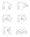
図2(a)から図2(e)は、血圧計1を被測定者8の左腕8aの手首に装着し、血圧測定を開始するまでの腕の移動状態を説明するために模式的に表した図である。図2(f)は、被測定者を頭頂部より見下ろした状態を示す図であり、被測定者の胸部前面を説明する図である。
2 (a) to 2 (e) are schematic views for explaining the movement state of the arm from when the
図2(a)に示すように、血圧計1を装着し、図示しないスイッチ操作によって血圧測定を開始したときの状態である。例えば、血圧計1を左手首に装着し、右手でスイッチ操作する。
図2(b)に示す矢印のように徐々に左腕を移動させ、図2(c)に示す矢印のように、血圧計1が被測定者8の胸部前面8bに移動するようにする。この図2(b)と図2(c)とに示す腕(血圧計)の移動状態が第1の移動状態である。
As shown in FIG. 2A, the blood pressure monitor 1 is attached and blood pressure measurement is started by a switch operation (not shown). For example, the
The left arm is gradually moved as indicated by the arrow shown in FIG. 2B, and the
ところで、胸部前面8bは、図2(f)に示すように、身体の前面という意味を含む概念である。心臓は左胸か、左胸よりやや右寄りにある場合が多いから、その心臓の鼓動を検出するときは、左胸前が適していよう。しかし、マイクロ波ドップラセンサ21を用いているために、正確に左胸前でなくとも心臓の鼓動を検出することができる。例えば、左胸斜め横側(左わき腹の上、脇の下のやや下位置)であっても、胸中央、被測定者によっては右胸前であっても検出することができる。このため、発明者は、胸部前面という範囲を図2(f)に示す胸部前面8bのエリアを定義している。
By the way, the chest
その後、図2(d)に示すように、血圧計1が胸部前面8bの位置から、心臓81と同じ高さになる適正位置までさらに腕を移動させる。この移動状態が第2の移動状態である。なお、図2(e)は、血圧計1と心臓81との高さが同一となり、適正位置になった状態を示している。
Thereafter, as shown in FIG. 2 (d), the
血圧計1が第1の移動状態にあるときは、血圧計1自体が大きく動いている状態である。また、第2の移動状態にあるときは、血圧計1は小さく動いている状態である。
詳しくは後述するが、第1の移動状態であるときは、図1に示すマイクロ波ドップラセンサ21から出力される電気信号Eoの振幅を用いてそれを検出し、第2の移動状態にあるときは、電気信号Eoに含まれる信号の周波数成分(脈拍、呼吸、体動が混じった成分)を用いて、例えば脈波を検出し、この脈波により適正位置を見つけるのである。
When the
As will be described in detail later, when it is in the first movement state, it is detected using the amplitude of the electric signal Eo output from the
そして、脈波を検出したならば、その脈波から所定時間(例えば、1分間)当たりの脈拍数を算出し(呼吸であれば呼吸数を算出し)、被測定者がノンストレス状態か否かを調べる。
その結果、被測定者がノンストレス状態であるときに、その検出結果を基に血圧測定を行うために拘束を開始する(カフにエアを送るなど)時期を決定し、血圧を測定する。
If a pulse wave is detected, the pulse rate per predetermined time (for example, 1 minute) is calculated from the pulse wave (respiration rate is calculated if breathing), and whether or not the measurement subject is in a non-stress state. Find out.
As a result, when the person to be measured is in a non-stress state, the timing for starting restraint (such as sending air to the cuff) to measure blood pressure based on the detection result is determined, and the blood pressure is measured.
このように、マイクロ波ドップラセンサから出力される電気信号の振幅と周波数とを、それぞれ2つの移動状態の検出に使うという点が、本発明の血圧計の特徴であり、脈拍、呼吸による被測定者のストレス状態の測定と、血圧測定時に血圧計が適正位置にあるか否かの測定とを同時に行なう。 In this way, the feature of the sphygmomanometer of the present invention is that the amplitude and frequency of the electrical signal output from the microwave Doppler sensor are used for detection of two movement states, respectively, and the measurement by pulse and respiration is performed. Measurement of a person's stress state and measurement of whether or not the sphygmomanometer is in an appropriate position at the time of blood pressure measurement are performed simultaneously.
なお、以下の説明において、マイクロ波ドップラセンサ21を用い、電気信号Eoから生体の動きを検出する手法を「マイクロ波センシング」と略記する。
In the following description, a technique for detecting the movement of the living body from the electric signal Eo using the
[血圧計の構成説明:図3]
次に、図3を用いて血圧計の構成を説明する。
図3は本発明による血圧計の、機能的な構成を説明する機能ブロック図である。
[Configuration explanation of blood pressure monitor: Fig. 3]
Next, the configuration of the sphygmomanometer will be described with reference to FIG.
FIG. 3 is a functional block diagram illustrating a functional configuration of the sphygmomanometer according to the present invention.
図3において、血圧計1は、血圧測定部位が心臓の高さに対して適正か否かを検出する適正位置検出手段2と、血圧を測定し表示する血圧測定手段3と、測定結果を視覚的に表示する表示部41及びアラーム音や音声といった音響手段で報知する報知部42を備える報知手段4と、測定開始スイッチ5、日時などの時刻情報を生成する計時回路6とを有している。なお、すでに説明した構成には同一の番号を付与している。
In FIG. 3, a
[適正位置検出手段2の説明]
まず、適正位置検出手段2の構成を説明する。
図3に示すように、適正位置検出手段2は、第1の移動検出手段25と第2の移動検出手段24とで構成している。
第1の移動検出手段25は、マイクロ波Meを発信し反射波Mtを受信するマイクロ波ドップラセンサ21と、第1の時間情報T1に基づきマイクロ波ドップラセンサ21の出力である電気信号Eoをデジタル信号Doに変換する変換器(以下、AD変換器と略記する)22と、デジタル信号Doが飽和状態になったことを検出し第1の移動状態が終了したことを告げる第1の移動状態終了信号Dsを出力する信号飽和検出回路23と、で構成している。
第2の移動検出手段24は、FFT回路242と、脈波検出回路243と、血圧測定判定回路245と、測定条件メモリ244と、で構成しており、血圧測定信号Msを出力する。
[Explanation of proper position detecting means 2]
First, the configuration of the appropriate
As shown in FIG. 3, the appropriate position detection means 2 is composed of a first movement detection means 25 and a second movement detection means 24.
The first movement detection means 25 digitally transmits an electric signal Eo that is an output of the
The second
更に詳細には、第2の移動検出手段24は、第2の時間情報T2に基づきデジタル信号Doを所定時間蓄積してFFT(Fast Fourier Transform:高速フーリエ変換、以下FFTと略記する)処理により周波数スペクトラム情報である基本波Bfを出力するFFT回路242と、基本波Bfを入力して脈波データPoを出力する脈波検出回路243と、脈波データPoを入力して血圧測定信号Msを出力する血圧測定判定回路245とで構成される。
More specifically, the second
詳しくは後述するが、脈波検出回路243が出力する脈波データPoを統計的に処理することにより脈波を得ることができる。血圧測定判定回路245は、この脈波データPoから脈拍数を算出できる。例えば、図示はしないが、計時回路6から時間情報を得て1分間の脈拍数として算出する。そして、その脈拍数が分かれば被測定者の精神的安定状態又は肉体的安静状態を知ることができる。
As will be described in detail later, a pulse wave can be obtained by statistically processing the pulse wave data Po output from the pulse
ところで、一般的に安静時における成人の脈拍数は、60〜80と言われている。例えば、男性で60〜70程度、女性で65〜80程度であるとも言われている。
また、脈拍数が早くなったときの限界的な数値(最大脈拍数とも呼ばれる)は、220から年齢を引いた値程度と言われており、一例をあげると、45歳人の場合は、1分間に175拍である。
By the way, it is generally said that an adult's pulse rate at rest is 60-80. For example, it is said that it is about 60-70 for men and about 65-80 for women.
In addition, the limit value (also called the maximum pulse rate) when the pulse rate becomes faster is said to be about the value obtained by subtracting age from 220. For example, in the case of a 45-year-old person, 1 175 beats per minute.
そこで、血圧測定判定回路245は、内部メモリ245aに予めこれらの数値を図示しない入力手段を用いて記憶しておき、脈波データPoから算出した脈拍数と比較して安静状態か否かを比べる。そして、安静状態と判定したとき、血圧測定信号Msを出力する。
Therefore, the blood pressure
血圧測定信号Msは、脈拍数と所定の範囲とを比較してレベル分けする情報を含んでいてもよい。内部メモリ245aに記憶していた一般的な脈拍数(男性で60〜70、女性で65〜80)と、脈波データPoから算出した脈拍数とを比較して安静状態をレベル分けしてもよいのである。
例えば、男性の場合の60〜70、女性の場合の65〜80という数値に対して、その範囲であればレベル3、それよりも5程度大小するならばレベル2、それを超えればレベル1などとしてもよい。
The blood pressure measurement signal Ms may include information for comparing levels by comparing the pulse rate with a predetermined range. Even if the general pulse rate (60 to 70 for men and 65 to 80 for women) stored in the internal memory 245a is compared with the pulse rate calculated from the pulse wave data Po, the resting state is divided into levels. It's good.
For example, with respect to the numerical values of 60 to 70 for males and 65 to 80 for females, it is
詳しくは後述するが、血圧測定判定回路245が血圧測定信号Msを出力し、血圧測定制御回路37が脈拍数などの血圧情報Kjを報知手段4に出力するが、このとき、測定した脈拍数をそのまま表示するようにしてもよい。そうすると、被験者は、自身の脈拍数を知ることができる。このとき、仮に脈拍数が高ければ、被験者は深呼吸などしてリラックスするようにできる。
As will be described in detail later, the blood pressure
第2の移動検出手段24は、脈波データPoと血圧測定信号Msとを必要に応じ記憶し、血圧測定情報記憶信号Mssとして出力する測定条件メモリ244を備えている。
The second movement detection means 24 includes a
この血圧測定信号Msが出力されたということは、血圧測定のための準備ができたということであり、血圧測定のために被測定者への拘束を開始する(後述するカフを加圧する)時期が決定したということである。
この実施形態で例示した構成では、被測定者の精神的安定状態又は肉体的安静状態の測定と、血圧測定のための適正位置の計測とを同時に行なうため、第2の移動検出手段24から血圧測定のための準備ができたことを示す信号を出力することになっている。
The fact that the blood pressure measurement signal Ms has been output means that preparation for blood pressure measurement has been completed, and the time to start restraint on the measurement subject (pressurization of a cuff described later) for blood pressure measurement. Is decided.
In the configuration exemplified in this embodiment, since the measurement of the mental stability state or the physical rest state of the measurement subject and the measurement of the appropriate position for blood pressure measurement are performed at the same time, the blood pressure is detected from the second movement detection means 24. A signal indicating that the measurement is ready is to be output.
計時回路6は、図示はしないが、例えば、水晶振動子などを用いて所定の周波数のクロック信号を出力する源振クロック部、そのクロック信号を分周して所定の分周信号を生成する分周回路部、その分周信号から時刻情報を生成する時刻生成部などで構成することができる。これらの構成は知られている時計回路で広く知られているものであるから、詳細な説明は省略する。
Although not shown, the
この計時回路6からは、第1の時間情報T1、第2の時間情報T2、第3の時間情報T3を出力している。
第1の時間情報T1は、AD変換器22のサンプリング時間を決めるための時刻情報を有しており、例えば、パルス周期を10msecとした信号である。
第2の時間情報T2は、FFT回路にデジタル信号Doを蓄積するための所定の時間を得るための時刻情報を有しており、例えば、パルス周期を10〜30secとしたパルス信号である。
第3の時間情報T3は、血圧測定を行なったときの日付や時間情報を有する時刻情報である。
The
The first time information T1 has time information for determining the sampling time of the
The second time information T2 has time information for obtaining a predetermined time for storing the digital signal Do in the FFT circuit, and is, for example, a pulse signal with a pulse period of 10 to 30 sec.
The third time information T3 is time information having date and time information when blood pressure measurement is performed.
[血圧測定手段3の構成説明]
次に、血圧測定手段3の構成を説明する。
血圧測定手段3は、カフ31と、圧力センサ32と、加圧ポンプ33と、加圧制御回路34と、排気バルブ35と、排気制御回路36と、血圧測定制御回路37と、で構成している。
[Description of Configuration of Blood Pressure Measuring Unit 3]
Next, the configuration of the blood
The blood pressure measuring means 3 includes a
カフ31は、手首の橈骨動脈を加圧して血流を阻止するための帯状の部材である。圧力センサ32は、カフ31の圧力を電気信号に変換して圧力信号Soとして出力する。加圧ポンプ33は、カフ31を加圧するためのポンプである。加圧制御回路34は、血圧測定制御回路37からの加圧制御信号Kcに基づき加圧駆動信号Kdを出力し加圧ポンプ33を駆動する。
The
排気バルブ35は、カフ31の圧力を所定の割合で排気するためのバルブである。排気制御回路36は、血圧測定制御回路37からの排気制御信号Hcに基づき排気駆動信号Hdを出力し排気バルブ35を制御する。
The
血圧測定制御回路37は、圧力信号Soと、血圧測定信号Msと、必要に応じ血圧測定情報記憶信号Mssとから、最高血圧や最低血圧や脈拍数や血圧測定信号Msからなる適正位置情報や血圧測定時の時刻情報などを含む血圧情報Kjおよび適正報知信号Tpを出力すると共に、血圧計1の動作を全般的に制御管理する。
血圧測定制御回路37の血圧情報メモリ371は、その血圧情報Kjを記憶するためのメモリ手段である。
なお、この血圧測定制御回路37は、特に限定しないが、ワンチップマイクロコンピュータなどで構成すると、小型で低消費電力化ができるので便利である。
The blood pressure
The blood pressure information memory 371 of the blood pressure
The blood pressure
[報知手段4の構成説明:図3、図6]
次に、図3および図6を用いて報知手段4の構成を説明する。
図6は、報知手段4の報知例を説明する図である。報知手段4は、血圧計1の血圧測定部位が心臓の高さと同一となる適正位置にあるか否かや測定した血圧値を表示するものである。血圧測定制御回路37が出力する最高及び最低血圧や脈拍数などの血圧情報Kjを表示する表示部41と、音声や音や光や振動で被測定者に報知する報知部42と、から構成している。
[Description of Configuration of Notification Unit 4: FIGS. 3 and 6]
Next, the structure of the alerting | reporting means 4 is demonstrated using FIG. 3 and FIG.
FIG. 6 is a diagram for explaining a notification example of the notification means 4. The notifying means 4 displays whether or not the blood pressure measurement site of the
図6に示すように、表示部41は最高血圧値表示部411と、最低血圧値表示部412と、脈拍数表示部413と、脈拍条件表示部415aを備えた測定条件表示部415と、血圧測定した日時などの時刻情報を表示する時刻表示部416と、を有しており、血圧測定手段3の血圧測定制御回路37が出力する最高血圧や最低血圧や脈拍数や血圧測定信号Msからなる血圧情報Kjを表示する。
As shown in FIG. 6, the
脈拍条件表示部415aは血圧測定信号Msのレベルに応じ、LEDなどを用いてマークや光で報知する。
例えば、血圧測定信号Msのレベルを3段階とすると、適正位置であるときをレベル3なら「○」を表示し、やや適正位置からずれているときのレベル2なら「△」を表示し、適正位置から大幅にずれているときのレベル1なら「×」を表示するような、複数のマークによる表示を行なうようにしてもよい。
The pulse
For example, if the blood pressure measurement signal Ms has three levels, “○” is displayed when the level is 3 and “△” is displayed when the level is slightly shifted from the proper position. If it is
また、LED光の色でレベルを表示するようにしてもよい。例えば、レベル3を「青」、レベル2を「黄」、レベル1を「赤」などとしてもよい。もちろん、マークや光を組み合わせて表示してもかまわない。
Moreover, you may make it display a level with the color of LED light. For example,
図6に示す例では、マークを用いて適正位置を報知する場合であって、図6(a)は、血圧測定信号Msがレベル3の場合であり「〇」マークを表示し、図6(b)は、血圧測
定信号Msがレベル1の場合であり「×」マークを表示する例である。
In the example shown in FIG. 6, a proper position is notified using a mark, and FIG. 6A shows a case where the blood pressure measurement signal Ms is
なお、図6に示す例では、脈拍数が血圧測定に対して適正であるか、被測定部位が適正位置にあるかを分けて表現しておらず1つのマークを表しているが、もちろん、双方のマークを表示しても構わない。 In the example shown in FIG. 6, it is not expressed separately whether the pulse rate is appropriate for blood pressure measurement or the measurement site is in the appropriate position, but of course, one mark is shown. Both marks may be displayed.
図6に示す例では、最高血圧値表示部411、最低血圧値表示部412、脈拍数表示部413、測定条件表示部415、時刻表示部416の各要素が独立した表示体とする例を示しているが、表示部41には1つの液晶表示装置などを用いて、各要素をエリアを分けて表示するようにしてもよい。
In the example shown in FIG. 6, an example is shown in which each element of the systolic blood pressure value display unit 411, the systolic blood pressure value display unit 412, the pulse rate display unit 413, the measurement condition display unit 415, and the time display unit 416 is an independent display body. However, the
報知部42は、ダイナミックスピーカやピエゾ音響素子などで構成することができる。アラーム音や、「血圧計の位置が適正位置です」又は「血圧計の位置が適切位置ではありません」などの音声で報知することができる。
このように、光やマーク、又は音声で適正位置に導くように案内することができるので、被測定者は血圧計を正しく適正位置にもって行くことができる。
The notification unit 42 can be configured by a dynamic speaker, a piezoelectric acoustic element, or the like. An alarm sound or a voice such as “the position of the sphygmomanometer is an appropriate position” or “the position of the sphygmomanometer is not an appropriate position” can be notified.
Thus, since it can guide so that it may guide to an appropriate position with light, a mark, or a voice, a person to be measured can take a blood pressure meter to an appropriate position correctly.
血圧測定時は、リラックスした姿勢で望むのがよいため、血圧計を胸部前面に位置しているときに、このように音声やアラーム音でその状況を報知できれば、目視による情報認識のために首を下に向けるなどする必要も無く、リラックスした姿勢を維持できて便利である。 When measuring blood pressure, it is desirable to have a relaxed posture, so when the blood pressure monitor is positioned in front of the chest, if the situation can be reported by voice or alarm sound, the neck can be used for visual recognition. It is convenient that you can maintain a relaxed posture without having to turn your head down.
本発明の血圧計は、脈拍数を測定できるので血圧測定時の被測定者の状態を、測定した血圧値と共に記録できる。そして報知手段によりいつでもその情報を知ることができる。そうすれば、血圧値と被測定者の状態を管理することができるようになるので、被測定者の健康状態や仮面高血圧などを知るきっかけにもなる。 Since the sphygmomanometer of the present invention can measure the pulse rate, it can record the state of the subject at the time of blood pressure measurement together with the measured blood pressure value. The information can be known at any time by the notification means. By doing so, it becomes possible to manage the blood pressure value and the condition of the person being measured, which is also an opportunity to know the health condition of the person being measured, masked hypertension and the like.
[第1の実施形態の動作説明:図3、図4]
次に、図3および図4を用いて血圧計の第1の実施形態の動作を説明する。
まず、適正位置検出手段2の動作説明を行なう。
図3において、被測定者8が血圧計1を手首(図示せず)に装着し測定開始スイッチ5を押すと、マイクロ波ドップラセンサ21から発信された約2.5GHzのマイクロ波Meは被測定者8で反射され、反射波Mtとしてマイクロ波受信器212で受信される。
[Description of Operation of First Embodiment: FIGS. 3 and 4]
Next, the operation of the first embodiment of the sphygmomanometer will be described with reference to FIGS. 3 and 4.
First, the operation of the appropriate position detecting means 2 will be described.
In FIG. 3, when the person to be measured 8 wears the
マイクロ波ドップラセンサ21は、マイクロ波Meに基づく送信マイクロ波信号Emeと、反射波Mtに基づく受信マイクロ波信号Emtとによる電気信号Eoを第1の移動検出手段25のAD変換器22に出力する。マイクロ波ドップラセンサ21の詳細の動作は図1を用いて詳述したので重複する説明は省略する。
The
AD変換器22は、電気信号EoをAD変換して時系列のデジタル信号Doとして信号飽和検出回路23及び第2の移動検出手段24に出力する。
The
信号飽和検出回路23は、デジタル信号Doを入力して、デジタル信号Doのデータ変化量が、所定の振幅範囲を予め定められた回数を超えると、第1の移動状態終了信号Dsを第2の移動検出手段24に出力する。
When the signal
第2の移動検出手段24は、デジタル信号Doを入力として血圧測定信号Msを血圧測定手段3に出力する。
第2の移動検出手段24のFFT回路242は、第2の時間情報T2に基づきデジタル信号Doを所定時間蓄積しFFT処理を行なう。このFFT処理は、入力信号を高速フー
リエ変換処理を行なうものである。すなわち、蓄積したデジタル信号Doをフーリエ変換し、個々の信号成分に分解した後、各成分を周波数スペクトラム上に表す処理を行い、基本波Bfとして脈拍波検出回路243に出力する。
The second
The
脈拍波検出回路243は、基本波Bfを入力して、基本波Bfの中の脈拍に係わる周波数帯域の成分を抽出し、脈波データPoとして測定条件メモリ244及び血圧測定判定回路245に出力する。
The pulse
第1の移動検出手段25の信号飽和検出回路23及び第2の移動検出手段24の動作を図2及び図4を用いてさらに詳述する。
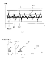
図4は、適正位置検出手段2の第1の移動検出手段25及び第2の移動検出手段24の動作を説明するために模式的に示す波形図である。図4(a)は、横軸に時間(T)を、縦軸にデジタル信号Doの振幅を示しており、デジタル信号Do、つまりマイクロ波ドップラセンサ21から出力される信号の時間的変化を表したものである。
The operations of the signal
FIG. 4 is a waveform diagram schematically illustrating the operation of the first movement detection unit 25 and the second
図4(a)の区間Aは、手首に血圧計1を装着し、測定開始スイッチ5を押した後、血圧計1を被測定者8の胸に近づくときの時間領域を表している。これは、図2(a)から図2(c)に示した第1の移動状態を示している。
A section A in FIG. 4A represents a time region when the
図4(a)に示すDxは第1の飽和閾値、Dmは第2の飽和閾値を示している。この第1の飽和閾値Dxと第2の飽和閾値Dmとの間が、所定の振幅範囲Drとなっている。また、Dsは第1の移動状態終了信号である。
第1の飽和閾値Dx及び第2の飽和閾値Dmは、予め決められた値を使うことができる。2つの閾値で決めているので、所定の振幅範囲Drを設定することができる。図4(a)に示す例では、第2の飽和閾値Dmはゼロとしており、いわゆるゼロ飽和閾値となっており、所定の振幅値を閾値とした第1の飽和閾値Dx(いわゆるプラス飽和閾値)との間が所定の振幅範囲Drとなっている。
Dx shown in FIG. 4A is a first saturation threshold, and Dm is a second saturation threshold. A predetermined amplitude range Dr is between the first saturation threshold Dx and the second saturation threshold Dm. Ds is a first movement state end signal.
As the first saturation threshold Dx and the second saturation threshold Dm, predetermined values can be used. Since it is determined by the two threshold values, the predetermined amplitude range Dr can be set. In the example shown in FIG. 4A, the second saturation threshold Dm is zero, which is a so-called zero saturation threshold, and a first saturation threshold Dx (so-called plus saturation threshold) having a predetermined amplitude value as a threshold. Is a predetermined amplitude range Dr.
区間A(第1の移動状態)のとき、被測定者8の生体表面でのマイクロ波の反射に、腕の移動が加わるのでドップラシフトが増大し、デジタル信号Doが急激に大きくなる。第1の移動検出手段25の信号飽和検出回路23は、デジタル信号Doが所定の振幅範囲Drを超えた回数を計測する。この回数は、予め実験などによりその数を選ぶなどして設定しておくとよいが、例えば、10回とする。デジタル信号Doが所定の振幅範囲Drを10回超えると第1の移動状態の最中であることが検出される。
In the section A (first movement state), since the movement of the arm is added to the reflection of the microwave on the living body surface of the
図4(a)の区間A´は、図4(a)の区間Aの終わりの部分であって、第1の移動状態が終了したときの時間領域である。
図2(a)から図2(c)及び図2(f)を用いて説明したように、腕を大きく動かして被測定者8の胸部前面8bに腕を移動させる第1の移動状態は、血圧計1が図2(c)に示す胸部前面8bの心臓に近い位置に来たときに終了する。すなわち、区間A´でデジタル信号Doが所定の振幅範囲Drの範囲内に収まるようになると、腕を大きく動かしていない、つまり第1の移動状態は終了したと判断する。このときのデジタル信号Doを、第1の移動状態終了信号Dsとしている。
The section A ′ in FIG. 4A is the end portion of the section A in FIG. 4A and is a time region when the first movement state is finished.
As described with reference to FIGS. 2 (a) to 2 (c) and 2 (f), the first movement state in which the arm is moved largely to the chest
第2の移動検出手段24は、第1の移動検出手段25から出力されたデジタル信号Doを入力して信号処理をするが、第1の移動状態終了信号Dsが入力されて初めてその処理を開始する。第1の移動状態が終了していないうちに信号処理を開始しないためである。
The second
図4(a)の区間Bは、手首を心臓近くに留置した状態の時間領域を示している。これは、図2(d)から図2(e)に示した第2の移動状態を示している。
区間Bでは、腕の大きな移動動作が無くなったものの、脈拍を検出するため及び適正位置を探すために小さく腕を動かしているため、所定の振幅範囲Drを超えないデジタル信号Doが検出される。この区間Bの波形には、心臓の拍動による波形も含まれている。
A section B in FIG. 4A shows a time region in a state where the wrist is placed near the heart. This shows the second movement state shown in FIGS. 2D to 2E.
In the section B, although the large movement movement of the arm disappears, the arm is moved small in order to detect the pulse and to search for an appropriate position, so the digital signal Do not exceeding the predetermined amplitude range Dr is detected. The waveform of this section B includes a waveform due to the heartbeat.
図4(b)は、図4(a)に示す区間Bにおけるデジタル信号Doの一部を拡大して示したものである。この時間領域を区間Dとする。このデジタル信号Doには、検出された被測定者8の心臓の拍動成分が含まれており、例えば、P1,P2,P3とする。 FIG. 4B is an enlarged view of a part of the digital signal Do in the section B shown in FIG. This time domain is defined as section D. This digital signal Do includes the detected pulsation component of the heart of the person to be measured 8 and is set to P1, P2, and P3, for example.
図4(c)は、FFT回路242によりデジタル信号Doを高速フーリエ変換処理をした波形を模式的に示す図である。X軸が周波数、Y軸を各周波数成分の信号の強さとした、周波数スペクトラム分布図である。
図4(a)の区間Bにおいて、第2の時間情報T2に基づきデジタル信号Doを所定時間蓄積して高速フーリエ変換を行い、図4(c)に示すような周波数成分の基本波Bfを得る。
FIG. 4C is a diagram schematically showing a waveform obtained by subjecting the digital signal Do to the fast Fourier transform processing by the
In the section B of FIG. 4A, the digital signal Do is accumulated for a predetermined time based on the second time information T2, and fast Fourier transform is performed to obtain a fundamental wave Bf having a frequency component as shown in FIG. .
第2の移動検出手段24は、基本波Bfから所定の周波数範囲から脈波データPoを算出する。
図4(c)に示すLfは第1の周波数閾値、Hfは第2の周波数閾値である。この第1の周波数閾値Lfと第2の周波数閾値Hfとの間が、所定の周波数範囲Df1となっている。この周波数範囲は、脈波を捉える範囲でなければならない。発明者が実験した結果によれば、例えば、第1の周波数閾値Lfを0.5Hz近辺、第2の周波数閾値Hfを3.0Hz近辺とすることで脈波を捉えることができた。
The
Lf shown in FIG. 4C is a first frequency threshold, and Hf is a second frequency threshold. A predetermined frequency range Df1 is between the first frequency threshold value Lf and the second frequency threshold value Hf. This frequency range must be a range that captures pulse waves. According to the results of experiments conducted by the inventor, for example, the pulse wave can be captured by setting the first frequency threshold Lf to around 0.5 Hz and the second frequency threshold Hf to around 3.0 Hz.
そして、脈波検出回路243は、基本波Bfのうち、所定の周波数範囲Df1に含まれる周波数スペクトラム分布を脈波データPoとして出力するのであるが、脈波データPoが正常に検出されていれば、脈拍数も算出できるということであると共に、第2の移動状態は終了し、図2(e)に示すように血圧計1と心臓81とが同一の高さとなる適正位置になっているということである。
The pulse
血圧測定判定回路245は、入力した脈波データPoを分析する。脈波データPoは、周波数成分のスペクトラム分布であるから、その周波数成分やパワー強度、あるいは平均、分散、標準偏差などの統計処理を行なうことができる。そしてその処理結果で、血圧測定に適正であれば、血圧測定信号Msを血圧測定手段3に出力する。
The blood pressure
図4(c)に示すように、所定の周波数範囲Df1内の周波数スペクトラム分布が脈波データPoであるから、第1の周波数閾値Lfと第2の周波数閾値Hfとが適する閾値であれば、脈波として適する波形が必ず含まれている。統計処理により、例えば、脈波データPoに含まれる各波形のピークを算出し、そのピークの出現傾向などで脈波を判定してもよい。例えば、2回続けて波形の強さが上がるものを脈波であるとすることができる。 As shown in FIG. 4C, since the frequency spectrum distribution in the predetermined frequency range Df1 is the pulse wave data Po, if the first frequency threshold value Lf and the second frequency threshold value Hf are suitable threshold values, A waveform suitable as a pulse wave is always included. For example, the peak of each waveform included in the pulse wave data Po may be calculated by statistical processing, and the pulse wave may be determined based on the appearance tendency of the peak. For example, a pulse wave that has a waveform whose intensity increases twice in succession can be determined.
この脈波データPoの分析により、脈波が特定でき、例えば1分間の脈拍の数である脈拍数も算出できる。 By analyzing this pulse wave data Po, the pulse wave can be identified, and for example, the pulse rate which is the number of pulses per minute can also be calculated.
そして、そのように統計処理した結果で、適正な脈拍数か適正位置かどうかを判定して血圧測定信号Msを出力するのである。
血圧測定信号Msとしては、適正度を表す1,2,3の3段階の数値などを用いることができる。例えば、脈拍数の場合は数値の範囲で適正度を決めることができる。適正位置の場合は、ピークの強さで適正度を決めることができる。ピークが最も強いところが適正位置であり、それよりも弱いところが適正位置からややずれている、などとすることができる。
Then, based on the result of such statistical processing, it is determined whether the pulse rate is appropriate or the proper position, and the blood pressure measurement signal Ms is output.
As the blood pressure measurement signal Ms, three-stage numerical values such as 1, 2, and 3 representing the appropriateness can be used. For example, in the case of a pulse rate, the appropriateness can be determined within a numerical range. In the case of an appropriate position, the appropriateness can be determined by the strength of the peak. It can be said that the place where the peak is the strongest is the appropriate position, and the place where the peak is weak is slightly shifted from the appropriate position.
もちろん、図4(c)の縦軸の各周波数成分の信号の強さに対して1つ又は複数の閾値を設け、その閾値を超えたもので適正度を分けることができる。この場合、その閾値は、事前に設定しておいてもよいし、脈波データPoを統計処理してその出現傾向から閾値を算出して用いるようにしてもよい。 Of course, it is possible to provide one or a plurality of threshold values for the signal strength of each frequency component on the vertical axis in FIG. In this case, the threshold may be set in advance, or may be used by statistically processing the pulse wave data Po and calculating the threshold from the appearance tendency.
すでに説明したように、第2の移動検出手段24の動作は、第1の移動検出手段25の信号飽和検出回路23の出力である第1の移動状態終了信号Dsによって制御され、第1の移動状態終了信号Dsが入力されていないと第2の移動検出手段24は動作を行わない。こうすることによって、第1の移動状態検出の後に第2の移動状態検出がなされることが担保される。
As already described, the operation of the second
測定条件メモリ244は、脈波データPoと血圧測定信号Msを関連付けて記憶しておき、過去のデータ推移などが必要な場合に血圧測定情報記憶信号Mssとして血圧測定手段3に出力する。
The
[血圧測定手段3の動作説明:図3〜図6]
次に、図3を用いて血圧測定手段3の動作を説明する。
図3において、適正位置検出手段2の血圧測定判定回路245は、被測定者8の手首に装着された血圧計1の心臓高さに対する位置の適性度を、血圧測定信号Msとして血圧測定手段38の血圧測定制御回路37に出力する。
[Explanation of the operation of the blood pressure measurement means 3: FIGS. 3 to 6]
Next, the operation of the blood
In FIG. 3, the blood pressure
血圧測定制御回路37は、報知手段4の表示部41に血圧測定信号Msを出力する。表示部41の測定条件表示部415の脈拍条件表示部415aには、血圧測定信号Msの例えば3段階のレベルに応じて「○」,「△」,「×」などのマークを表示する。
The blood pressure
血圧測定制御回路37は、また、報知手段4の報知部42に血圧測定信号Msを出力する。報知部42は、血圧測定信号Msによって「体が血圧測定できる状態です」又は「体が血圧測定に適する状態にはありません」、「血圧計の位置が適正位置です」又は「血圧計の位置が適切位置ではありません」などと、音声による報知が行われる。
The blood pressure
もちろん、ブザー音で血圧測定信号Msの3段階のレベルに応じて異なる音色で報知することや、振動モータを用いて異なる振動で血圧測定信号Msの3段階のレベルを報知することなどとしてもよい。 Of course, the buzzer sound may be used for notification in different tones according to the three levels of the blood pressure measurement signal Ms, or the three levels of the blood pressure measurement signal Ms may be notified using different vibrations using a vibration motor. .
そして、血圧測定制御回路37は、血圧測定信号Msに基づき以下に述べるように、血圧測定制御の動作を制御する。
The blood pressure
血圧計1が適正位置であるときをレベル3とすると、血圧測定制御回路37は、レベル3の血圧測定信号Msが入力されると、加圧制御回路34に加圧制御信号Kcを出力し、加圧ポンプ33は加圧制御回路34が出力する加圧駆動信号Kdを受けてカフ31を加圧する
Assuming that the
圧力センサ32によってカフ31の圧力は刻々と血圧測定制御回路37に出力され、カフ31が所定の圧力まで加圧されると、血圧測定制御回路37は加圧制御回路34を制御して加圧ポンプ33の動作を停止する。
The pressure of the
血圧測定制御回路37は、排気制御信号Hcを排気制御回路36に出力し、排気制御回路36は、排気制御信号Hcに基づき排気バルブ35を制御する排気駆動信号Hdを排気バルブ35に出力する。
The blood pressure
排気バルブ35は、排気駆動信号Hdに基づき、カフ31の圧力が時間に対して一定の割合で減少する様にカフ31を排気する。
カフ31の圧力が次第に下がると、被測定者8の手首の血圧に応じていわゆるオシロメトリック理論に基づく圧力振動波形(図示せず)がカフ31内に生じるので、圧力センサ32によってこれを検出する。
The
When the pressure of the
血圧測定制御回路37は、圧力センサ32の圧力信号Soの圧力振動波形から、最高血圧値や最低血圧値、脈拍数などを血圧情報Kjとして血圧情報メモリ371に記憶すると共に、報知手段4の表示部41に出力する。
The blood pressure
血圧情報メモリ371には、脈拍数などと血圧値とを対応させて記憶しておくことで、後から測定したときの体の状態を知ることができて便利である。
計時回路6から第3の時間情報T3を入力し、血圧測定を行なったときの日付や時間情報の時刻情報も合わせて記憶しておけば、後から血圧測定前の脈拍数や測定した血圧値などがいつのものか分かるので便利である。
In the blood pressure information memory 371, it is convenient to know the state of the body when measured later by storing the pulse rate and the blood pressure value in association with each other.
If the third time information T3 is inputted from the
血圧測定中の適正位置の監視について説明する。
血圧測定中に血圧計1と心臓との高さが変わってしまうことがある。適性位置で血圧測定を開始しても、計測の途中で腕が下がるなどして適正位置から外れてしまうと、計測した血圧値は信用度のおけるものではなくなる。このように腕が適正位置から外れるなどの状態を被測定者が意図せずに起こしてしまったとき、被測定者自身では正しい血圧を測定したつもりでも、実際には正しくない血圧測定を行ってしまう。
The monitoring of the appropriate position during blood pressure measurement will be described.
The height of the
そのような状況を回避するため、血圧計1は、その位置が適正位置になり血圧測定を開始したあとも、マイクロ波センシングを継続し、適正位置であるか否かを監視することができる。
第2の移動状態が終了して血圧測定が開始されても、脈波データPoのピークを監視し、血圧測定信号Msを出力する。
血圧測定信号Msが変化したときに、報知手段4を用いて報知する。例えば、「適正位置からずれました」などと報知する。また、血圧測定信号Msのレベルが、大きく変化したとき、血測定を中断する。例えば、適正位置であるときのレベル3から、適正位置から大幅にずれているときのレベル1に変化したときには、腕が心臓位置からずれてしまったとし、報知手段4にて「血圧測定を中止します」などと報知するなどし、血圧測定を中断する。
In order to avoid such a situation, the
Even when the second movement state ends and blood pressure measurement is started, the peak of the pulse wave data Po is monitored and the blood pressure measurement signal Ms is output.
When the blood pressure measurement signal Ms changes, the notification means 4 is used for notification. For example, it is notified that “deviation from the proper position”. Further, when the level of the blood pressure measurement signal Ms changes greatly, the blood measurement is interrupted. For example, when the level is changed from
ところで、被測定者の都合で適正位置による血圧測定ではないが、とにかく血圧値を知りたいという場合もある。そのときは、測定開始スイッチ5などを操作して、強制的に血圧測定を開始することもできる。
By the way, it is not the blood pressure measurement at the proper position for the convenience of the person to be measured, but there are cases where the user wants to know the blood pressure value anyway. At that time, the blood pressure measurement can be forcibly started by operating the
[動作フローの説明:図3、図5、図6]
次に、主に図5を用いて、血圧計1による血圧測定の動作フローを詳述する。図5は、血圧計1を手首に装着し、血圧測定が終了するまでの動作を説明するフローチャートである。以下、動作ステップはS1、S2、・・、Snのように略記する。
[Description of Operation Flow: FIGS. 3, 5, and 6]
Next, the operation flow of blood pressure measurement by the
まず、被測定者8は血圧計1を手首に装着し測定開始スイッチ5を押す。(S1)
すると、図3に示す適正位置検出手段2によって、マイクロ波センシング動作が開始される。(S2)
First, the person under
Then, the microwave sensing operation is started by the appropriate position detection means 2 shown in FIG. (S2)
被測定者8が血圧計1を装着した手首を胸部前面まで移動させる(第1の移動状態)。
その間、信号飽和検出回路23によって、デジタル信号Doの振幅が所定の振幅範囲Drを超える回数を計測する。腕の大きな移動が終了するとデジタル信号Doは所定の振幅範囲Drに収まり、第1の移動状態が終了すると信号飽和検出回路23が第1の移動状態終了信号Dsを出力する。
The person under
Meanwhile, the signal
報知手段4の報知部42によって音や光で、あるいは音声で「血圧計は適正な位置にあります」などの報知が行われる。
被測定者8が手首を胸に近づけ方が不足していたり、近づけ方が適切でない場合は、「血圧計の位置が適切ではありません」、又は「もう一度血圧計を胸に近づけて下さい」等の音声報知がなされる。(S3)
The notifying unit 42 of the notifying
If the person under
図3に示す第2の移動検出手段24のFFT回路242は、第2の時間情報T2に基づきデジタル信号Doを所定時間蓄積する。(S4)
The
FFT回路242は、デジタル信号DoをFFT処理し、基本波Bfを算出する。(S5)
The
図3に示す第2の移動検出手段24の脈拍波検出回路243にて、基本波Bfより脈波データPoを出力する。
実験などにより、予め脈波の周波数スペクトル分布を0.5Hz近辺から3.0Hz近辺であるとすると、その周波数範囲に入る脈波データPoの検出をもって、胸部前面にて血圧計1と心臓とが同一の高さとなったことを知ることができる。これが第2の移動状態検出である。(S6)
The pulse wave data Po is output from the fundamental wave Bf by the pulse
If the frequency spectrum distribution of the pulse wave is preliminarily in the vicinity of 0.5 Hz to 3.0 Hz by an experiment or the like, the
胸部前面にて血圧計1と心臓とが同一の高さとはならないときは、脈波データPoが検出されないから、警告音や警告表示を行う。例えば、「血圧計をさらに上に上げてください」や「血圧計をさらに下げてください」などを報知手段4を用いて報知する。
When the
また、胸部前面にて血圧計1と心臓との距離が離れすぎていても脈波データPoは検出されないことがある。そのときは、「さらに血圧計を胸に近づけてください」等の報知がなされる。
Further, the pulse wave data Po may not be detected even if the
図3に示す第2の移動検出手段24の血圧測定判定回路245にて、血圧測定信号Msを、例えば3段階のレベルで出力する。そのレベルを報知手段4を用いて、脈拍数や心臓高さの適性度に応じ異なるブザー音やマークで報知する。そして、血圧測定手段3にて血圧測定が開始される。(S7)
The blood pressure
血圧測定中も血圧測定信号Msを監視してもよく、その結果に応じて、その内容を、報知手段4を用いて報知する。例えば、血圧計1が適正位置からずれてしまったときは、その旨を報知したり、血圧測定を中断する。(S7´)
The blood pressure measurement signal Ms may be monitored during the blood pressure measurement, and the content is notified using the notification means 4 according to the result. For example, when the
血圧測定手段3において、血圧測定が終了する。(S8)
また、血圧測定中もマイクロ波センシングを続け、適正位置からのずれを検出したとき(S7´)は、マイクロ波センシングと血圧測定とを終了する。(S8´)
In the blood pressure measuring means 3, the blood pressure measurement ends. (S8)
Further, the microwave sensing is continued during the blood pressure measurement, and when the deviation from the appropriate position is detected (S7 ′), the microwave sensing and the blood pressure measurement are terminated. (S8 ')
血圧測定制御回路37の血圧情報メモリ371は、最高血圧値や最低血圧値および脈拍数などの血圧情報と血圧測定信号Msを記憶する。(S9)
The blood pressure information memory 371 of the blood pressure
血圧情報メモリ371に記憶した情報は、報知手段4にて報知する。
測定開始スイッチ5を押して測定を終了する。(S10)
Information stored in the blood pressure information memory 371 is notified by the notification means 4.
Press the
[第1の実施形態の効果説明]
まず、従来の電子血圧計が抱える根本的な問題を考えてみる。
従来の電子血圧計は、例えば、手首を被測定部位としたとき、血圧測定時の腕の状態を知ることはできなかった。つまり、腕自体が上がっているか下がっているかや、腕を無理に曲げるなどして無理な姿勢としていないかなどは分からなかった。血圧計と心臓との高さが同一であれば正しく血圧測定がなされたという考えでいたため、体に掛かる負担などは考慮に入れずに血圧測定がなされていた。
[Explanation of Effects of First Embodiment]
First, let's consider the fundamental problems of conventional electronic blood pressure monitors.
Conventional electronic sphygmomanometers cannot know the state of the arm during blood pressure measurement, for example, when the wrist is the measurement site. In other words, I did not know whether the arm itself was raised or lowered, or whether it was impossible to bend by forcibly bending the arm. The idea was that blood pressure was correctly measured if the height of the sphygmomanometer and the heart were the same, so blood pressure was measured without taking into consideration the burden on the body.
また、血圧測定に臨むときの被測定者の肉体的安静状態や精神的な安定状態を知ることもできなかった。つまり、リラックスして血圧測定に臨んだのか、自身では落ち着いていると思い込んでいるが実は歩行など他の動作を行った直後で脈拍数が高い状態になっていたのかなどが分からなかった。 In addition, it was impossible to know the physical rest state and mental stability state of the measurement subject when taking blood pressure measurement. In other words, I thought I was relaxed and started to measure blood pressure, or I thought I was calm, but I wasn't sure if my pulse rate was high immediately after other actions such as walking.
しかし、本発明の血圧計は、その従来の電子血圧計が抱える根本的な問題を解決する。
本発明の血圧計は、血圧測定に臨むときの脈拍数も知り得ることができるため、腕自体を無理に上げたり曲げたりするような無理な姿勢で血圧測定に臨んだとしても、そのような姿勢でいれば体に負担が掛かるため脈拍数に現れる。このため、血圧測定開始直前において、血圧計と心臓とが同一の高さにあることはもちろん、体に無理のかからない姿勢で血圧測定ができたか否かということも分かる。つまり、血圧測定前に無理な姿勢かどうかを判断し、かつ適性位置で血圧測定ができるよう誘導できるという、いわば本質的な意味での正しい血圧測定を行なうことができるのである。
そして、血圧測定直前の脈拍数から、血圧測定に臨むときの被測定者の肉体的安静状態や精神的な安定状態も知ることができる。
However, the sphygmomanometer of the present invention solves the fundamental problem of the conventional electronic sphygmomanometer.
Since the sphygmomanometer of the present invention can also know the pulse rate at the time of blood pressure measurement, even if the blood pressure measurement is performed in an unreasonable posture such as forcibly raising or bending the arm itself, If you are in a posture, it will appear in your pulse rate because it puts a burden on your body. For this reason, immediately before the start of blood pressure measurement, it is understood that the blood pressure meter and the heart are at the same height, as well as whether or not the blood pressure can be measured in a posture that does not force the body. That is, it is possible to perform correct blood pressure measurement in an essential sense that it is possible to determine whether the posture is impossible before blood pressure measurement and to be able to perform blood pressure measurement at an appropriate position.
Then, from the pulse rate immediately before blood pressure measurement, it is possible to know the physical resting state and the mentally stable state of the person to be measured when the blood pressure measurement is started.
マイクロ波ドップラセンサにより正しく適正位置に腕部を誘導できた結果、その適正位置による血圧測定が行えたこと、そして血圧測定に臨むときの被測定者の肉体的安静状態や精神的な安定状態を表すとされる脈拍数を記録することもできるため、血圧測定後、いつでもそれらの情報を知り得ることができる。
すなわち、本発明の血圧計は、測定した血圧値が正しい測定によりなされたことが証明できることに加え、血圧値と被測定者の状態も記録できるのである。
As a result of correctly guiding the arm to the appropriate position with the microwave Doppler sensor, blood pressure measurement was possible at the appropriate position, and the physical resting state and mental stability of the subject when taking the blood pressure measurement Since the pulse rate to be expressed can be recorded, the information can be obtained at any time after blood pressure measurement.
That is, the sphygmomanometer of the present invention can record the blood pressure value and the state of the person to be measured, in addition to being able to prove that the measured blood pressure value was obtained by correct measurement.
本発明の血圧計を用いれば、例えば、24時間自由行動下での複数回の血圧測定による血圧値の変化を調べるときであっても、被測定者の肉体的安静状態や精神的な安定状態の変化も詳しく知り得ることができて便利である。 With the sphygmomanometer of the present invention, for example, even when examining changes in blood pressure values by multiple blood pressure measurements under 24 hours free behavior, the subject's physical resting state and mental stability state It is convenient to know the changes in
次に、図7〜図10を用いて、本発明の血圧計の第2の実施形態について説明する。
第2の実施形態の特徴は、被測定者の呼吸数を検出する呼吸波検出回路をさらに備えている点である。マイクロ波センシングにより被測定者の呼吸波成分も検出し、血圧計10の心臓の高さに対する位置検出は脈拍数で調べ、呼吸の情報を加味して身体の安静状態をより正確に把握するものである。
Next, a second embodiment of the sphygmomanometer according to the present invention will be described with reference to FIGS.
The feature of the second embodiment is that it further includes a respiratory wave detection circuit that detects the respiratory rate of the measurement subject. The respiratory wave component of the person to be measured is detected by microwave sensing, the position of the
なお、以下の説明において、同一要素には同一番号を付与するが、第1の実施形態と区別するため、血圧計は記号10を付与し、第2の移動検出手段は記号26を付与している。なお、重複する説明は省略する。
In the following description, the same number is assigned to the same element. In order to distinguish it from the first embodiment, the sphygmomanometer is assigned the
図7は、第2の実施形態である血圧計10の機能ブロック図であり、第2の移動検出手段26の一部及び血圧測定手段3の一部を示している。図10は第2の実施形態である血圧計10の表示例を説明する図である。
FIG. 7 is a functional block diagram of the
[第2の移動検出手段26の構成説明:図7]
図7に示すように、適正位置検出手段2の第2の移動検出手段26は、呼吸波検出回路246を備えている。呼吸波検出回路246はFFT回路242が出力する基本波Bfを入力として基本波Bfに含まれる呼吸に係わる情報を抽出し呼吸波データRcとして血圧測定手段3の血圧測定制御回路37に出力する。
[Description of Configuration of Second Movement Detection Unit 26: FIG. 7]
As shown in FIG. 7, the second movement detection unit 26 of the appropriate
[表示部41の構成説明:図10 ]
図10に示すように、表示部41は最高血圧値表示部411と、最低血圧値表示部412と、脈拍数表示部413と、脈拍条件表示部415a及び呼吸条件表示部415bを備えた測定条件表示部415と、血圧測定した日時などの時刻情報を表示する時刻表示部416と、に加えて呼吸数表示部414を有している。
血圧測定手段3の血圧測定制御回路37が出力する最高血圧や最低血圧や脈拍数や呼吸数、血圧測定信号Msからなる血圧情報Kjを表示する。
[Configuration Description of Display Unit 41: FIG. 10]
As shown in FIG. 10, the
The blood pressure information Kj including the highest blood pressure, the lowest blood pressure, the pulse rate, the respiratory rate, and the blood pressure measurement signal Ms output from the blood pressure
図10(a)は呼吸波データRcに関わる情報から表示する場合を示し、図10(b)は呼吸波データRcが入力されなかった場合の表示例である。呼吸条件表示部415bには、それぞれ「○」、「×」でその状態を示している。 FIG. 10A shows a case where information is displayed from information related to the respiratory wave data Rc, and FIG. 10B is a display example when no respiratory wave data Rc is input. In the respiration condition display part 415b, the state is indicated by “◯” and “X”, respectively.
[第2の実施形態の動作説明:図7、図8、図10]
次に、図7、図8、図10を用いて血圧計10の動作を説明する。
図8は、適正位置検出手段2の第2の移動検出手段26の動作を説明する波形図である。図8において、図8(a)は、図4(b)に、図8(b)は図4(c)にそれぞれ相当する。
[Description of Operation of Second Embodiment: FIGS. 7, 8, and 10]
Next, the operation of the
FIG. 8 is a waveform diagram for explaining the operation of the second movement detection means 26 of the appropriate position detection means 2. 8, FIG. 8 (a) corresponds to FIG. 4 (b), and FIG. 8 (b) corresponds to FIG. 4 (c).
すでに説明したように、図4(a)の区間Bは、手首を心臓近くに留置した状態の時間領域を示しており、図2(d)から図2(e)に示した第2の移動状態を示している。区間Bでは、腕の大きな移動動作が無くなったものの、適正位置を探すために小さく腕を動かしているため、所定の振幅範囲Drを超えないデジタル信号Doが検出され、この区間Bの波形には、心臓の拍動による波形と、呼吸によって胸部が動く体動の波形とが含まれている。 As described above, the section B in FIG. 4A shows the time region in which the wrist is placed near the heart, and the second movement shown in FIGS. 2D to 2E. Indicates the state. In section B, although the arm's large movement is lost, the arm is moved small to find an appropriate position, so a digital signal Do that does not exceed the predetermined amplitude range Dr is detected. The waveform of the heart beat and the waveform of the body movement in which the chest moves by breathing are included.
図8(a)は、図4(a)に示す区間Bにおけるデジタル信号Doの一部を拡大して示したものであり、図8(a)に示すデジタル信号Doには、検出された被測定者8の呼吸による成分も含まれており、例えば、R1,R2とする。
FIG. 8A is an enlarged view of a part of the digital signal Do in the section B shown in FIG. 4A, and the detected digital signal Do shown in FIG. Components due to the respiration of the
図8(b)は、FFT回路242によりデジタル信号Doを高速フーリエ変換処理をした波形を模式的に示す図であり、周波数スペクトラム分布図である。この波形が基本波Bfである。
FIG. 8B is a diagram schematically showing a waveform obtained by subjecting the digital signal Do to the fast Fourier transform processing by the
第2の移動検出手段26は、基本波Bfから所定の周波数範囲から脈波データPo及び呼吸波データRcを算出する。
図8(b)に示すLfpは第3の周波数閾値、Hfpは第4の周波数閾値である。この第3の周波数閾値Lfpと第4の周波数閾値Hfpとの間が、所定の周波数範囲Df2となっている。この周波数範囲は、呼吸を捉える範囲でなければならない。発明者が実験した結果によれば、例えば、第3の周波数閾値Lfpを0.06Hz近辺、第4の周波数閾値Hfpを0.4Hz近辺とすることで安静状態における呼吸を捉えることができた。
The second movement detecting means 26 calculates the pulse wave data Po and the respiratory wave data Rc from the predetermined frequency range from the fundamental wave Bf.
Lfp shown in FIG. 8B is a third frequency threshold, and Hfp is a fourth frequency threshold. A predetermined frequency range Df2 is between the third frequency threshold Lfp and the fourth frequency threshold Hfp. This frequency range must be a range that captures breathing. According to the results of experiments conducted by the inventor, for example, the third frequency threshold Lfp is set to around 0.06 Hz, and the fourth frequency threshold Hfp is set to around 0.4 Hz.
脈波検出回路243は、基本波Bfのうち、所定の周波数範囲Df1に含まれる周波数スペクトラム分布を脈波データPoとして出力するのであるが、脈波データPoが正常に
検出されていれば、第2の移動状態は終了し、図2(e)に示すように血圧計1と心臓81とが同一の高さとなる適正位置になっているということはすでに説明したとおりである。
The pulse
そして、呼吸波検出回路246は、基本波Bfのうち、所定の周波数範囲Df2に含まれる周波数スペクトラム分布を呼吸波データRcとして出力するのである。なお、呼吸波データRcは、第2の移動状態の検出には関係しない。
The respiratory
呼吸波検出回路246が出力する呼吸波データRcを統計的に処理することにより呼吸数を得ることができる。血圧測定判定回路245は、この呼吸波データRcから呼吸数を算出できる。例えば、図示はしないが、計時回路6から時間情報を得て1分間の呼吸数として算出する。そして、その呼吸数が分かれば被測定者の精神的安定状態又は肉体的安静状態を知ることができる。
The respiratory rate can be obtained by statistically processing the respiratory wave data Rc output from the respiratory
ところで、一般的に安静時における成人の呼吸数は、1分間に10〜15と言われている。そこで、血圧測定判定回路245は、内部メモリ245aに予めこの数値を記憶しておき、呼吸波データRcから算出した呼吸数と比較して安静状態か否かを比べる。そして、安静状態と判定したとき、血圧測定信号Msを出力する。
Incidentally, it is generally said that the respiration rate of an adult at rest is 10 to 15 per minute. Therefore, the blood pressure
脈拍数の場合と同様に、血圧測定信号Msは、呼吸数と所定の範囲とを比較してレベル分けしてする情報を含んでいてもよい。上述の如く、一般的な呼吸数は、1分間に10〜15である。そこで、血圧測定判定回路245は、内部メモリ245aに記憶していたこれらの数値と、呼吸データRcから算出した呼吸数とを比較して安静状態をレベル分けしてもよいのである。
例えば、呼吸数10〜15という数値に対して、その範囲であればレベル3、それよりも3程度大小するならばレベル2、それを超えればレベル1などとしてもよい。
As in the case of the pulse rate, the blood pressure measurement signal Ms may include information that compares the respiratory rate with a predetermined range and divides the level. As mentioned above, a typical respiration rate is 10-15 per minute. Therefore, the blood pressure
For example, with respect to a numerical value of 10 to 15, the level may be
血圧測定判定回路245が血圧測定信号Msを出力し、血圧測定制御回路37が呼吸数などの血圧情報Kjを報知手段4に出力するが、このとき、血圧測定信号Msの情報(レベル)に基づいて、マークで表示してもよい。例えば、レベル3なら「〇」、レベル2なら「△」、レベル1なら「×」などとしてもよい。
The blood pressure
また、測定した呼吸数をそのまま表示するようにしてもよい。そうすると、被験者は、自身の呼吸数を知ることができる。このとき、仮に呼吸数が高ければ、被験者は、知られているリラックスする呼吸法(例えば、ゆっくり鼻から吸い、ゆっくり口で吐くなど)を試しリラックスするようにできる。 Moreover, you may make it display the measured respiration rate as it is. Then, the subject can know his / her respiration rate. At this time, if the respiration rate is high, the subject can try and relax by using a known relaxing breathing method (for example, slowly sucking from the nose and slowly exhaling with the mouth).
血圧測定手段3の血圧測定制御回路37には、圧力センサ32からの圧力信号Soと適正位置検出手段2の血圧測定判定回路245からの血圧測定信号Msが加えられる。
The blood pressure
血圧測定手段3の血圧測定制御回路37は、血圧測定信号Msの情報により血圧測定の動作を行わないなどとすることもできる。例えば、呼吸波検出回路246が出力する呼吸波データRcが予め定められた範囲、例えば最大値Rchと最小値Rclの範囲になっていないときなどである。
The blood pressure
なお、呼吸波データRcとしては、以上述べたように呼吸数や呼吸周期などの原データの他に、呼吸数や呼吸周期の平均値や標準偏差など、各種の統計指標を用いることもできる。 In addition to the original data such as the respiratory rate and the respiratory cycle, as described above, various statistical indexes such as the average value and standard deviation of the respiratory rate and the respiratory cycle can be used as the respiratory wave data Rc.
もちろん、血圧情報メモリ371には、呼吸数などと血圧値とを対応させて記憶してお
くこともできる。第1の実施形態と同様に脈拍数も記憶してもよい。こうすれば、後から測定したときの体の状態を知ることができて便利である。
計時回路6から第3の時間情報T3を入力し、血圧測定を行なったときの日付や時間情報の時刻情報も合わせて記憶しておけば、後から血圧測定前の呼吸数や測定した血圧値などがいつのものか分かるので便利である。
Of course, the blood pressure information memory 371 can store the respiratory rate and the blood pressure value in association with each other. As in the first embodiment, the pulse rate may also be stored. In this way, it is convenient to know the state of the body when measured later.
If the third time information T3 is input from the
血圧測定手段3の血圧測定制御回路37は、血圧測定条件が整うと報知手段4の報知部42は血圧測定が可能であることをブザー音などで報知し、血圧測定が開始される。
The blood pressure
[動作フローの説明:図7、図9、図10]
次に、主に図9を用いて、血圧計10による血圧測定の動作フローを詳述する。図9は、血圧計10を手首に装着し、血圧測定が終了するまでの動作のうち、第2の移動状態検出のステップ以降を示すフローチャートである。以下、第1の実施形態と同様に動作ステップはS61、S7、・・、Snのように略記する。
[Description of Operation Flow: FIGS. 7, 9, and 10]
Next, an operation flow of blood pressure measurement by the
図9において、S1からS5までは第1の実施形態と同じなので説明は省略するものであり、S61においては、図7の第2の移動検出手段26の呼吸波検出回路246は、第3の周波数閾値と第4の周波数閾値である0.06Hz〜0.4Hzの範囲の周波数成分を呼吸波データRcとして検出する。脈波検出回路243による脈波データPoの検出は第1の実施形態と同じなので説明は省略する。(S61)
In FIG. 9, since S1 to S5 are the same as those in the first embodiment, the description thereof will be omitted. In S61, the respiratory
S7からS8は第1の実施形態と同じなので説明は省略する。
S91においては、血圧値と測定条件と呼吸数をメモリに記憶する。(S91)
これ以降のステップは、第1の実施形態と同じなので説明は省略する。
Since S7 to S8 are the same as in the first embodiment, a description thereof will be omitted.
In S91, the blood pressure value, measurement conditions, and respiratory rate are stored in the memory. (S91)
Subsequent steps are the same as those in the first embodiment, and a description thereof will be omitted.
[第2の実施形態の効果説明]
以上説明したように、本発明の血圧計10によれば、適正位置による血圧測定を行ったこと、そして血圧測定に臨むときの被測定者の肉体的や精神的な状態を表すとされる脈拍数に加え呼吸数を測定及び記録することで、血圧測定後、いつでもそれらの情報を知り得ることができる。
つまり、測定した血圧値が正しい測定によりなされている信頼できる値であるかが証明できることに加え、血圧値と被測定者の状態も記録できるので、例えば、24時間自由行動下での複数回の血圧測定による血圧値の変化を調べるときであっても、被測定者の肉体的や精神的な安定状態の変化もより詳しく知り得ることができるので便利である。
[Explanation of Effects of Second Embodiment]
As described above, according to the
In other words, in addition to being able to prove whether the measured blood pressure value is a reliable value made by a correct measurement, it is also possible to record the blood pressure value and the state of the person being measured. Even when examining changes in blood pressure values due to blood pressure measurements, it is convenient because changes in the physical and mental stability of the subject can be known in more detail.
以上の第2の実施形態の説明にあっては、マイクロ波センシングにより被測定者の脈波と呼吸波成分とを検出し、血圧計の心臓の高さに対する位置検出は脈拍数で調べ、呼吸の情報で身体の安静状態を把握するものを示した。もちろん、脈波検出の部分を省略して呼吸のみで行なってもよい。つまり、血圧計の高さに対する位置検出も呼吸を用いて行なってもよいのである。 In the description of the second embodiment described above, the pulse wave and respiratory wave component of the measurement subject are detected by microwave sensing, the position detection of the sphygmomanometer with respect to the heart height is examined by the pulse rate, The information to grasp the resting state of the body was shown. Of course, the pulse wave detection portion may be omitted and the respiration may be performed only. That is, position detection with respect to the height of the sphygmomanometer may also be performed using respiration.
[応用例1の説明]
第1の実施形態と第2の実施形態とを用いて、本発明の血圧計を説明したが、本発明の主旨を逸脱しない範囲での変更はもちろん可能である。
例えば、血圧測定判定回路245の内部メモリ245aや血圧測定制御回路37の血圧情報メモリ371などに、被測定者の平常時の脈拍数や呼吸数を予め記録したり、過去に測定したこれらの数値から平均的な脈拍数や呼吸数を算出して記録しておき、血圧測定に望むときに、新たに測定した脈拍数や呼吸数と記録してあるそれらとを比較して、「通常よりも脈拍数が高いです」や「通常よりも呼吸数が多いです」などと報知手段4を用いて報知してもよい。
[Description of Application Example 1]
Although the sphygmomanometer of the present invention has been described using the first embodiment and the second embodiment, it is of course possible to make changes without departing from the gist of the present invention.
For example, the normal pulse rate and respiration rate of the measurement subject are recorded in advance in the internal memory 245a of the blood pressure
そうすれば、被測定者が自身のそのときの体調などを知ることができて便利である。また、血圧測定に臨むときに被測定者が無意識のうちに腕を無理に曲げていたなどの体に負担の掛かる姿勢をとっていたとしても、通常よりも高い脈拍数や呼吸数であれば、報知手段4を用いて「リラックスしましょう」や「正しい姿勢で測定しましょう」などと報知することにより、正しい血圧測定に案内することもできる。 This is convenient because the person being measured can know his / her physical condition at that time. In addition, even if the subject takes a posture that puts a burden on the body, such as unconsciously bending his arm unconsciously, when the blood pressure measurement is started, if the pulse rate or breathing rate is higher than usual Then, by using the notification means 4 to notify “Let's relax” or “Measure with the correct posture”, it is possible to guide to the correct blood pressure measurement.
上述の応用例を、第1の実施形態を例にして説明する。
予め基底脈拍数を記憶しておく例である。例えば、就寝直前、起床直前、座位30分以上経過したときなどは、被測定者が安静になっているときとされており、このような状況で測定した脈拍数を基底安静時脈拍数と呼ぶ。この基底安静時脈拍数を予め測定し記憶しておけば、これを現在の脈拍数(血圧を測定の臨むときの脈拍数)と比較してその差分量(ΔPLS)から、被測定者の肉体的安静状態や精神的安定状態を把握することができる。差分量は以下の式を用いる。
The application example described above will be described using the first embodiment as an example.
This is an example in which the basal pulse rate is stored in advance. For example, immediately before going to bed, immediately before getting up, or when sitting for more than 30 minutes, it is considered that the person being measured is at rest, and the pulse rate measured in such a situation is called the basal pulse rate at rest. . If this basal resting pulse rate is measured and stored in advance, it is compared with the current pulse rate (the pulse rate when blood pressure is measured) and the difference amount (ΔPLS) is used to calculate the body of the subject. It is possible to grasp the state of mental rest and mental stability. The following formula is used for the difference amount.
ΔPLS=現在の脈拍数−基底安静時脈拍数 ΔPLS = Current pulse rate-Basal resting pulse rate
そして、血圧測定判定回路245は、例えば、ΔPLSが「10未満」であればレベル3とし、ΔPLSが「10以上」であればレベル2、ΔPLSが「20以上」であればレベル1と判定し血圧測定信号Msとして出力する。
The blood pressure
[応用例2の説明]
また、別の応用もある。再び第1の実施形態を例にして説明する。
脈波間隔のゆらぎ成分の度合いを用いる例であって、自律神経のバランスからストレスの掛かり具合を知るのである。
[Description of Application Example 2]
There are also other applications. The first embodiment will be described again as an example.
In this example, the degree of fluctuation component of the pulse wave interval is used, and the degree of stress is known from the balance of autonomic nerves.
まず、所定の時間(例えば、数10秒)脈波を測定する。血圧計と心臓との適正位置を計測しているときに脈波を取得してもよい。そして、その脈波を線形予測分析する信号処理を実施する。すると、線形予測残差に含まれる脈波間隔のゆらぎを知ることができる。 First, a pulse wave is measured for a predetermined time (for example, several tens of seconds). A pulse wave may be acquired while measuring an appropriate position between the sphygmomanometer and the heart. And the signal processing which carries out the linear prediction analysis of the pulse wave is implemented. Then, the fluctuation of the pulse wave interval included in the linear prediction residual can be known.
つまり、線形予測分析して得られる脈波間隔を時系列的に並べて周波数解析を行なう。そうすると、0.15〜0.4Hzの高周波数成分(Hf)と、0.05〜0.15Hzの低周波数成分(LF)とに周波数ピークを見い出すことができる。
一般に、高周波数成分(Hf)は、副交感神経の高揚が反映され、低周波数成分(Lf)は、交感神経及び副交感神経の高揚が反映されるといわれている。ストレスが掛かっているときに、交感神経が高揚しているといわれることから、高周波数成分(HF)における低周波数成分(LF)の割合(X)から、自律神経のバランスを知ることができる。
That is, the frequency analysis is performed by arranging the pulse wave intervals obtained by the linear prediction analysis in time series. Then, frequency peaks can be found in the high frequency component (Hf) of 0.15 to 0.4 Hz and the low frequency component (LF) of 0.05 to 0.15 Hz.
In general, it is said that the high frequency component (Hf) reflects the uplift of the parasympathetic nerve, and the low frequency component (Lf) reflects the uplift of the sympathetic nerve and the parasympathetic nerve. Since it is said that the sympathetic nerve is elevated when stress is applied, the balance of the autonomic nerve can be known from the ratio (X) of the low frequency component (LF) to the high frequency component (HF).
具体的には、線形予測分析して得られる脈波間隔を時系列的に並べて周波数解析を行なったあと、その波形のうち、高周波数成分(HF)と低周波数成分(LF)との面積比を割合(X)とする。数式は次式のようになる。 Specifically, after performing the frequency analysis by arranging the pulse wave intervals obtained by the linear prediction analysis in time series, the area ratio of the high frequency component (HF) and the low frequency component (LF) in the waveform. Is the ratio (X). The formula is as follows.
X=LF/HF X = LF / HF
そして、血圧測定判定回路245は、例えば、Xが「0.5未満」であればレベル3とし、Xが「0.6以上」であればレベル2、Xが「1.0以上」であればレベル1と判定し血圧測定信号Msとして出力する。
For example, the blood pressure
以上説明した実施形態では、マイクロ波ドップラセンサを用いることで、被測定者の脈拍や呼吸の測定と血圧計の適正位置検出の測定とを同時に行なう例を示したが、これを別
々に行なっても構わない。もちろん、適正位置検出を省略してもよいことは無論である。
In the embodiment described above, an example is shown in which the measurement of the measurement subject's pulse and respiration and the measurement of the proper position of the sphygmomanometer are performed simultaneously by using the microwave Doppler sensor. It doesn't matter. Of course, it is a matter of course that proper position detection may be omitted.
また、本発明の血圧計を手首に装着する例を示したが、もちろん上腕部などに装着してもよい。また、カフと血圧計本体とが一体となる構成を例にして説明したが、別体としてもよいことは無論である。 Moreover, although the example in which the sphygmomanometer according to the present invention is worn on the wrist has been shown, it may of course be worn on the upper arm or the like. In addition, the configuration in which the cuff and the sphygmomanometer body are integrated has been described as an example, but it is needless to say that the cuff and the sphygmomanometer body may be separate.
大切なことは、血圧計を装着した被装着部位と心臓との高さが同一となる点と、体に負担の掛からない姿勢で血圧測定の臨む点とであるから、体に負担が掛からない範囲であっても腕部を不必要に持ち上げるなどの不自然な姿勢をしないこともまた装置運用上は重要である。 The important thing is that the height of the wearing part and the heart where the sphygmomanometer is worn are the same, and the point where blood pressure measurement is performed in a posture that does not place a burden on the body, so there is no burden on the body It is also important for the operation of the apparatus not to take an unnatural posture such as unnecessarily lifting the arm portion even within the range.
この発明は、被測定者の脈拍や呼吸を測定し、その結果から被測定者の精神的安定状態又は肉体的安静状態を正しく知ることができる。このため、正しい血圧測定ができる血圧計として好適である。 According to the present invention, the pulse and respiration of the measurement subject are measured, and the mental stability state or the physical rest state of the measurement subject can be accurately known from the measurement result. For this reason, it is suitable as a sphygmomanometer that can perform correct blood pressure measurement.
1、10 血圧計
2 適正位置検出手段
21 マイクロ波ドップラセンサ
211 マイクロ波発信器
212 マイクロ波受信器
213 マイクロ波ドップラ復調器
22 AD変換器
23 信号飽和検出回路
24、26 第2の移動検出手段
25 第1移動検出手段
241 基本波蓄積回路
242 FFT回路
243 脈波検出回路
244 測定条件メモリ
245 血圧測定判定回路
245a 内部メモリ
246 呼吸波検出回路
3 血圧測定手段
31 カフ
32 圧力センサ
33 加圧ポンプ
34 加圧制御回路
35 排気バルブ
36 排気制御回路
37 血圧測定制御回路
371 血圧情報メモリ
38 血圧計測定部
4 報知手段
41 表示部
411 最高血圧表示部
412 最低血圧表示部
413 脈拍数表示部
414 呼吸数表示部
415 測定条件表示部
415a 脈拍条件マーク表示部
415b 呼吸条件マーク表示部
416 時刻表示部
42 報知部
5 測定開始スイッチ
6 計時回路
8 被測定者
8a 左腕
8b 胸部前面
81 心臓
Me マイクロ波
Mt 反射波
Eme 送信マイクロ波信号
Emt 受信マイクロ波信号
Eo 電気信号
Do デジタル信号
Ds 第1の移動状態終了信号
Dr 所定の振幅範囲
Dx 第1の飽和閾値
Dm 第2の飽和閾値
Df1,Df2 所定の周波数範囲
Bf 基本波
Lf 第1の周波数閾値
Hf 第2の周波数閾値
Lfp 第3の周波数閾値
Hfp 第4の周波数閾値
Ms 血圧測定信号Ms
Mss 血圧測定情報記憶信号
Po 脈波データ
P1,P2,P3 心臓の拍動成分
Rc 呼吸波データ
Rch 最大値
Rcl 最小値
R1,R2 呼吸による成分
So 圧力信号
Kc 加圧制御信号
Hc 排気制御信号
Kd 加圧駆動信号
Hd 排気駆動信号
T1 第1の時間情報
T2 第2の時間情報
T3 第3の時間情報
1, 10 Sphygmomanometer 2 Appropriate position detection means 21 Microwave Doppler sensor 211 Microwave transmitter 212 Microwave receiver 213 Microwave Doppler demodulator 22 AD converter 23 Signal saturation detection circuit 24, 26 Second movement detection means 25 First movement detection means 241 Fundamental wave accumulation circuit 242 FFT circuit 243 Pulse wave detection circuit 244 Measurement condition memory 245 Blood pressure measurement determination circuit 245a Internal memory 246 Respiration wave detection circuit 3 Blood pressure measurement means 31 Cuff 32 Pressure sensor 33 Pressure pump 34 Addition Pressure control circuit 35 Exhaust valve 36 Exhaust control circuit 37 Blood pressure measurement control circuit 371 Blood pressure information memory 38 Blood pressure meter measurement unit 4 Notification means 41 Display unit 411 Systolic blood pressure display unit 412 Diastolic blood pressure display unit 413 Pulse rate display unit 414 Respiration rate display unit 415 Measurement condition display section 415a Pulse condition mark table Unit 415b breathing condition mark display unit 416 time display unit 42 notification unit 5 measurement start switch 6 timing circuit 8 measured person 8a left arm 8b chest front 81 heart Me microwave Mt reflected wave Eme transmission microwave signal Emt reception microwave signal Eo electricity Signal Do Digital signal Ds First movement state end signal Dr Predetermined amplitude range Dx First saturation threshold Dm Second saturation threshold Df1, Df2 Predetermined frequency range Bf Fundamental wave Lf First frequency threshold Hf Second frequency Threshold Lfp Third frequency threshold Hfp Fourth frequency threshold Ms Blood pressure measurement signal Ms
Mss Blood pressure measurement information storage signal Po Pulse wave data P1, P2, P3 Heart pulsation component Rc Respiration wave data Rch Maximum value Rcl Minimum value R1, R2 Respiration component So Pressure signal Kc Pressure control signal Hc Exhaust control signal Kd Add Pressure drive signal Hd Exhaust drive signal T1 First time information T2 Second time information T3 Third time information
Claims (5)
マイクロ波発生器とマイクロ波受信器とを備え、前記マイクロ波発生器より前記被測定者にマイクロ波を照射し、前記マイクロ波受信器により検出されるドップラシフトした反射波から、前記被測定者の脈拍、呼吸の少なくとも1つを検出し、この検出結果を基に前記拘束を開始する時期を決定し、血圧を測定することを特徴とする血圧計。 In a sphygmomanometer that measures blood pressure by restraining the measurement site of the subject,
A microwave generator and a microwave receiver; the microwave generator irradiates the person to be measured with microwaves; and the Doppler-shifted reflected wave detected by the microwave receiver detects the person to be measured. A sphygmomanometer that detects at least one of a pulse and a respiration, determines a timing for starting the restraint based on the detection result, and measures blood pressure.
前記決定は、前記脈拍数又は前記呼吸数と前記適正位置とを用いて行うことを特徴とする請求項2又は3に記載の血圧計。 An appropriate position detecting means for detecting an appropriate position where a relative height position between the measurement site and the heart of the subject is within an appropriate range;
The sphygmomanometer according to claim 2 or 3, wherein the determination is performed using the pulse rate or the respiratory rate and the appropriate position.
The sphygmomanometer according to claim 4, wherein the appropriate position detection unit detects the pulse or breath of the subject.
Priority Applications (1)
| Application Number | Priority Date | Filing Date | Title |
|---|---|---|---|
| JP2011017890A JP2012157435A (en) | 2011-01-31 | 2011-01-31 | Sphygmomanometer |
Applications Claiming Priority (1)
| Application Number | Priority Date | Filing Date | Title |
|---|---|---|---|
| JP2011017890A JP2012157435A (en) | 2011-01-31 | 2011-01-31 | Sphygmomanometer |
Publications (1)
| Publication Number | Publication Date |
|---|---|
| JP2012157435A true JP2012157435A (en) | 2012-08-23 |
Family
ID=46838496
Family Applications (1)
| Application Number | Title | Priority Date | Filing Date |
|---|---|---|---|
| JP2011017890A Pending JP2012157435A (en) | 2011-01-31 | 2011-01-31 | Sphygmomanometer |
Country Status (1)
| Country | Link |
|---|---|
| JP (1) | JP2012157435A (en) |
Cited By (9)
| Publication number | Priority date | Publication date | Assignee | Title |
|---|---|---|---|---|
| JP2013042840A (en) * | 2011-08-23 | 2013-03-04 | Citizen Holdings Co Ltd | Electronic sphygmomanometer |
| JP2014233529A (en) * | 2013-06-04 | 2014-12-15 | 株式会社村田製作所 | Blood pressure manometer |
| CN104619253A (en) * | 2012-09-10 | 2015-05-13 | 皇家飞利浦有限公司 | Device and method to improve dependability of physiological parameter measurements |
| CN104755016A (en) * | 2012-10-09 | 2015-07-01 | 皇家飞利浦有限公司 | System and method for breathing rate measurements |
| JP2016538005A (en) * | 2013-10-01 | 2016-12-08 | コーニンクレッカ フィリップス エヌ ヴェKoninklijke Philips N.V. | Improved signal selection for acquiring remote photoplethysmographic waveforms |
| JP2017176340A (en) * | 2016-03-29 | 2017-10-05 | シチズン時計株式会社 | Electronic sphygmomanometer |
| WO2019142720A1 (en) * | 2018-01-18 | 2019-07-25 | Joyson Safety Systems Japan株式会社 | Buckle, state of alertness determination system, and state of alertness determination method |
| WO2019198567A1 (en) * | 2018-04-12 | 2019-10-17 | オムロン株式会社 | Biological information measurement device, method and program |
| CN110392548A (en) * | 2017-03-14 | 2019-10-29 | 欧姆龙健康医疗事业株式会社 | Blood pressure data processing unit, blood pressure data processing method and blood pressure data processing routine |
-
2011
- 2011-01-31 JP JP2011017890A patent/JP2012157435A/en active Pending
Cited By (17)
| Publication number | Priority date | Publication date | Assignee | Title |
|---|---|---|---|---|
| JP2013042840A (en) * | 2011-08-23 | 2013-03-04 | Citizen Holdings Co Ltd | Electronic sphygmomanometer |
| US9936920B2 (en) | 2012-09-10 | 2018-04-10 | Koninklijke Philips N.V. | Device and method to improve dependability of physiological parameter measurements |
| JP2015531261A (en) * | 2012-09-10 | 2015-11-02 | コーニンクレッカ フィリップス エヌ ヴェKoninklijke Philips N.V. | Apparatus and method for improving the reliability of physiological parameter measurement |
| CN104619253A (en) * | 2012-09-10 | 2015-05-13 | 皇家飞利浦有限公司 | Device and method to improve dependability of physiological parameter measurements |
| JP2015535185A (en) * | 2012-10-09 | 2015-12-10 | コーニンクレッカ フィリップス エヌ ヴェKoninklijke Philips N.V. | System and method for measuring respiration rate |
| CN104755016A (en) * | 2012-10-09 | 2015-07-01 | 皇家飞利浦有限公司 | System and method for breathing rate measurements |
| US10213114B2 (en) | 2012-10-09 | 2019-02-26 | Koninklijke Philips N.V. | System and method for breathing rate measurements |
| JP2014233529A (en) * | 2013-06-04 | 2014-12-15 | 株式会社村田製作所 | Blood pressure manometer |
| JP2016538005A (en) * | 2013-10-01 | 2016-12-08 | コーニンクレッカ フィリップス エヌ ヴェKoninklijke Philips N.V. | Improved signal selection for acquiring remote photoplethysmographic waveforms |
| JP2017176340A (en) * | 2016-03-29 | 2017-10-05 | シチズン時計株式会社 | Electronic sphygmomanometer |
| CN110392548A (en) * | 2017-03-14 | 2019-10-29 | 欧姆龙健康医疗事业株式会社 | Blood pressure data processing unit, blood pressure data processing method and blood pressure data processing routine |
| CN110392548B (en) * | 2017-03-14 | 2022-05-03 | 欧姆龙健康医疗事业株式会社 | Blood pressure data processing device, blood pressure data processing method, and blood pressure data processing program |
| WO2019142720A1 (en) * | 2018-01-18 | 2019-07-25 | Joyson Safety Systems Japan株式会社 | Buckle, state of alertness determination system, and state of alertness determination method |
| JP2019122652A (en) * | 2018-01-18 | 2019-07-25 | Joyson Safety Systems Japan株式会社 | Buckle, arousal state determination system, and arousal state determination method |
| WO2019198567A1 (en) * | 2018-04-12 | 2019-10-17 | オムロン株式会社 | Biological information measurement device, method and program |
| JP2019180925A (en) * | 2018-04-12 | 2019-10-24 | オムロン株式会社 | Biological information measuring apparatus, method, and program |
| JP7154803B2 (en) | 2018-04-12 | 2022-10-18 | オムロン株式会社 | Biological information measuring device, method and program |
Similar Documents
| Publication | Publication Date | Title |
|---|---|---|
| JP5855004B2 (en) | Arm-mounted blood pressure monitor | |
| JP2012157435A (en) | Sphygmomanometer | |
| US20210244302A1 (en) | Methods to estimate the blood pressure and the arterial stiffness based on photoplethysmographic (ppg) signals | |
| US20190150755A1 (en) | Biological information analysis device, system, and program | |
| EP3125746B1 (en) | System and method for detecting variation of heart rate of a user | |
| US11224385B2 (en) | Method for determining a person's sleeping phase which is favourable for waking up | |
| JP3951708B2 (en) | Biological information evaluation device | |
| JP4342455B2 (en) | Health management device and health management system | |
| JP5626659B2 (en) | Apparatus and method for continuously measuring blood pressure for monitoring purposes | |
| RU2669744C2 (en) | Device and method to improve dependability of physiological parameter measurements | |
| US10405791B2 (en) | Method and continuously wearable noninvasive apparatus for automatically detecting a stroke and other abnormal health conditions | |
| KR101007354B1 (en) | Apparatus and method for measuring blood presure | |
| JP3940150B2 (en) | Caffres electronic blood pressure monitor | |
| EP3261526B1 (en) | Apparatus and method for providing a control signal for a blood pressure measurement device | |
| KR20180108664A (en) | A sleep state measuring apparatus and method, a phase coherence calculating apparatus, a living body vibration signal measuring apparatus, a stress state measuring apparatus and a sleep state measuring apparatus, and a heartbeat waveform extracting method | |
| JP7107531B2 (en) | Blood pressure calculation method and device | |
| JP2018501853A (en) | Device and method for measuring physiological characteristics of a subject | |
| WO2013165474A1 (en) | Continuously wearable non-invasive apparatus for detecting abnormal health conditions | |
| JP2001112725A (en) | Biological information measuring apparatus | |
| US20110184298A1 (en) | Portable cardio waveform acquisiton and heart rate variability (hrv) analysis | |
| Zhang et al. | Technology development for simultaneous wearable monitoring of cerebral hemodynamics and blood pressure | |
| WO2021024460A1 (en) | Sphygmomanometer | |
| RU2601697C2 (en) | Device and method for measuring human arterial pressure value | |
| WO2018066678A1 (en) | Estimation device, massage system, estimation method, and estimation program | |
| RU2424765C2 (en) | Compressive method of measuring physiological indices of organism state and device for its realisation |
Legal Events
| Date | Code | Title | Description |
|---|---|---|---|
| RD07 | Notification of extinguishment of power of attorney |
Free format text: JAPANESE INTERMEDIATE CODE: A7427 Effective date: 20130514 |