JP2012156836A - Remote controller and program - Google Patents
Remote controller and program Download PDFInfo
- Publication number
- JP2012156836A JP2012156836A JP2011014865A JP2011014865A JP2012156836A JP 2012156836 A JP2012156836 A JP 2012156836A JP 2011014865 A JP2011014865 A JP 2011014865A JP 2011014865 A JP2011014865 A JP 2011014865A JP 2012156836 A JP2012156836 A JP 2012156836A
- Authority
- JP
- Japan
- Prior art keywords
- remote control
- information
- unit
- recognition
- processing
- Prior art date
- Legal status (The legal status is an assumption and is not a legal conclusion. Google has not performed a legal analysis and makes no representation as to the accuracy of the status listed.)
- Withdrawn
Links
Images


Landscapes
- Selective Calling Equipment (AREA)
Abstract
Description
本発明は、リモコン装置及びプログラム等に関する。 The present invention relates to a remote control device, a program, and the like.
TV、DVDプレーヤー等の機器をリモコン操作するリモコン装置としては、機器専用のリモコン装置、マルチリモコン装置、学習型マルチリモコン装置などがある。 As remote control devices for remotely controlling devices such as TVs and DVD players, there are remote control devices dedicated to devices, multi-remote control devices, learning-type multi-remote control devices, and the like.
ここで、機器専用のリモコン装置では、機器ごとにリモコン装置を取り替える必要があり、ユーザーにとって煩雑であるという課題がある。また、家庭内にある機器1台に対してリモコン装置1台が必要となり、リモコン装置の台数が増えてしまう。 Here, in the remote control device dedicated to the device, it is necessary to replace the remote control device for each device, and there is a problem that it is complicated for the user. In addition, one remote control device is required for one device in the home, and the number of remote control devices increases.
マルチリモコン装置は、一般的にTV用マルチリモコン装置、エアコン用マルチリモコン装置のように、同一製品分野でメーカーごとに異なる制御信号に対応したものである。しかしながら、このマルチリモコン装置においても、やはり、家庭内にある機器ごとにリモコン装置が必要になるという問題がある。また、予め操作対象機器のメーカー名、機種情報をリモコン装置に設定する必要があり、ユーザーにとって煩雑である。 In general, the multi-remote control device corresponds to a control signal that differs depending on the manufacturer in the same product field, such as a multi-remote control device for TV and a multi-remote control device for air conditioner. However, this multi-remote control device still has a problem that a remote control device is required for each device in the home. Further, it is necessary to set the manufacturer name and model information of the operation target device in advance in the remote control device, which is troublesome for the user.
学習型マルチリモコン装置では、前述の機器専用のリモコン装置から送信される赤外線信号を記憶させることで、複数の機器を一台のリモコン装置で操作可能になる。しかしながら、この学習型マルチリモコン装置では、複数の機器の全てのリモコン操作を記憶させる設定入力が、ユーザーにとって煩雑である。また、多くのリモコン操作をリモコン装置に記憶させるためには、リモコン装置本体の操作ボタン数が膨大になってしまう。その上、リモコン装置に搭載される操作ボタンの配列は固定であるため、各操作と操作ボタンの意味づけが分かりにくく、ユーザーにとって使いにくいという問題がある。 In the learning type multi-remote control device, it is possible to operate a plurality of devices with one remote control device by storing the infrared signal transmitted from the above-described device-specific remote control device. However, in this learning type multi-remote control device, setting input for storing all remote control operations of a plurality of devices is complicated for the user. Further, in order to store many remote control operations in the remote control device, the number of operation buttons on the remote control device main body becomes enormous. In addition, since the arrangement of the operation buttons mounted on the remote control device is fixed, there is a problem that the meaning of each operation and the operation buttons is difficult to understand and is difficult for the user to use.
また特許文献1には、カメラが搭載されるリモコン装置が開示されている。この特許文献1の従来技術では、機器側から発せられる光の点滅で機器を識別している。
しかしながら、この従来技術では、リモコン操作の対象となる機器側に、赤外線LEDなどの情報伝達デバイスを設け、リモコン装置が、個々の個別情報を受け取って機器のリモコン操作を行う。このため、このような情報伝達デバイスを持たない既存の機器に対しては、この従来技術の手法を適用することが難しいという課題がある。 However, in this prior art, an information transmission device such as an infrared LED is provided on the device side that is the target of remote control operation, and the remote control device receives individual individual information and performs remote control operation of the device. For this reason, there is a problem that it is difficult to apply this conventional technique to existing equipment that does not have such an information transmission device.
即ち、家電機器等の一般的な機器はこのような赤外線LEDなどの情報伝達デバイスを備えているとは限らない。従って、上述の従来技術では、このような情報伝達デバイスを持たない機器からその機器情報を取得したり、リモコン操作することは困難である。 That is, general devices such as home appliances do not always include such an information transmission device such as an infrared LED. Therefore, in the above-described conventional technology, it is difficult to acquire the device information from a device that does not have such an information transmission device or to perform a remote control operation.
本発明の幾つかの態様によれば、リモコン操作対象機器を効率的に特定して操作可能にするリモコン装置及びプログラム等を提供できる。 According to some aspects of the present invention, it is possible to provide a remote control device, a program, and the like that can efficiently specify and operate a remote control target device.
本発明の一態様は、機器を撮像する撮像部と、機器の認識処理を行う認識部と、機器をリモコン操作するためのリモコン処理を行うリモコン処理部とを含み、前記認識部は、前記撮像画像の画像認識処理により、前記撮像画像に映る機器の識別マーカーのマーカー認識処理を行い、前記リモコン処理部は、前記マーカー認識処理の結果に基づいて、機器をリモコン操作するためのリモコン処理を行うリモコン装置に関係する。 One aspect of the present invention includes an imaging unit that images a device, a recognition unit that performs device recognition processing, and a remote control processing unit that performs remote control processing for remote-controlling the device, and the recognition unit includes the imaging Image recognition processing of the image performs marker recognition processing of the identification marker of the device shown in the captured image, and the remote control processing unit performs remote control processing for remote-controlling the device based on the result of the marker recognition processing Related to remote control device.
本発明の一態様によれば、撮像部からの撮像画像の画像認識処理により、撮像画像に映る機器の識別マーカーの形状認識処理が行われる。そして、このマーカー認識処理の結果に基づいて、機器をリモコン操作するためのリモコン処理が実行される。従って、例えば機器の識別マーカーのマーカー認識処理により機器を特定し、特定された機器についての種々のリモコン処理を実行できるようになるため、リモコン操作対象機器を効率的に特定して操作可能にするリモコン装置の提供が可能になる。 According to the aspect of the present invention, the shape recognition process of the identification marker of the device shown in the captured image is performed by the image recognition process of the captured image from the imaging unit. Based on the result of the marker recognition process, a remote control process for operating the device by remote control is executed. Accordingly, for example, a device can be specified by marker recognition processing of an identification marker of the device, and various remote control processes can be executed for the specified device. Therefore, it is possible to efficiently specify and operate a remote control target device. A remote control device can be provided.
また本発明の一態様では、前記リモコン処理部は、機器登録モードにおいて、前記マーカー認識処理により得られた機器の機器情報を、登録情報として登録してもよい。 In the aspect of the invention, the remote control processing unit may register the device information of the device obtained by the marker recognition process as registration information in the device registration mode.
このようにすれば、機器登録モードにおいてマーカー認識処理により得られた機器の機器情報を登録情報として登録し、他のモード等において登録情報の機器情報を使用することが可能になる。 This makes it possible to register the device information of the device obtained by the marker recognition process in the device registration mode as registration information, and use the device information of the registration information in other modes and the like.
また本発明の一態様では、前記機器情報を含む前記登録情報を記憶する記憶部を含み、前記リモコン処理部は、リモコン操作モードにおいて、前記登録情報を前記記憶部から読み出すことで、リモコン操作対象機器の前記機器情報を取得してもよい。 In one aspect of the present invention, the information processing apparatus includes a storage unit that stores the registration information including the device information. The remote control processing unit reads out the registration information from the storage unit in a remote control operation mode, thereby The device information of the device may be acquired.
このようにすれば、機器登録モードにおいてマーカー認識処理により得られた機器の機器情報を登録情報として登録し、リモコン操作モードにおいて登録情報の機器情報を取得して、リモコン操作対象機器のリモコン処理などを実行することが可能になる。 In this way, the device information of the device obtained by the marker recognition process in the device registration mode is registered as registration information, the device information of the registration information is acquired in the remote control operation mode, the remote control processing of the remote control operation target device, etc. Can be executed.
また本発明の一態様では、前記認識部は、前記機器登録モードにおいて、前記撮像画像の画像認識処理により、前記撮像画像に映る機器の形状認識処理を行い、前記リモコン処理部は、前記機器登録モードにおいて、前記機器登録モードでの形状認識処理により得られた機器の特徴量情報を、機器の登録特徴量情報として登録する処理を行い、前記記憶部は、前記マーカー認識処理により得られた前記機器情報と、前記形状認識処理により得られた前記登録特徴量情報とが関連づけられた情報を、前記登録情報として記憶し、前記認識部は、前記リモコン操作モードにおいて、前記撮像画像の画像認識処理により、前記撮像画像に映る機器の形状認識処理を行い、前記リモコン処理部は、前記リモコン操作モードにおいて、前記リモコン操作モードでの前記形状認識処理により得られた特徴量情報である機器特徴量情報と、前記登録特徴量情報との比較処理を行い、前記機器特徴量情報が前記登録特徴量情報に一致した機器の前記機器情報を前記記憶部から読み出すことで、リモコン操作対象機器の前記機器情報を取得してもよい。 In one aspect of the present invention, the recognition unit performs shape recognition processing of a device shown in the captured image by image recognition processing of the captured image in the device registration mode, and the remote control processing unit performs the device registration. In the mode, the device feature amount information obtained by the shape recognition process in the device registration mode is registered as the device registered feature amount information, and the storage unit is obtained by the marker recognition process. Information associated with device information and the registered feature amount information obtained by the shape recognition processing is stored as the registration information, and the recognition unit performs image recognition processing of the captured image in the remote control operation mode. The remote controller processing unit performs the remote controller operation in the remote controller operation mode. The device feature amount information, which is the feature amount information obtained by the shape recognition processing in the node, is compared with the registered feature amount information, and the device feature amount information matches the registered feature amount information. The device information of the remote control operation target device may be acquired by reading out the device information from the storage unit.
このようにすれば、機器登録モードにおいて、形状認識処理により得られた機器の登録特徴量情報を登録し、リモコン操作モードにおいて、登録特徴量情報と機器特徴量情報を比較することで、リモコン操作対象機器を選択できるようになる。従って、特徴量情報を利用した機器の効率的な選択処理を実現できる。 According to this configuration, the registered feature amount information of the device obtained by the shape recognition process is registered in the device registration mode, and the remote controller operation is performed by comparing the registered feature amount information with the device feature amount information in the remote control operation mode. The target device can be selected. Therefore, an efficient device selection process using the feature amount information can be realized.
また本発明の一態様では、前記リモコン処理部は、前記機器登録モードにおいて、前記機器登録モードでの前記マーカー認識処理により前記識別マーカーから取得された機器の特徴量情報を、機器の登録特徴量情報として登録する処理を行い、前記記憶部は、前記マーカー認識処理により得られた前記機器情報と、前記マーカー認識処理により得られた前記登録特徴量情報とが関連づけられた情報を、前記登録情報として記憶し、前記認識部は、前記リモコン操作モードにおいて、前記撮像画像の画像認識処理により、前記撮像画像に映る機器の形状認識処理を行い、前記リモコン処理部は、前記リモコン操作モードにおいて、前記リモコン操作モードでの前記形状認識処理により得られた特徴量情報である機器特徴量情報と、前記登録特徴量情報との比較処理を行い、前記機器特徴量情報が前記登録特徴量情報に一致した機器の前記機器情報を前記記憶部から読み出すことで、リモコン操作対象機器の前記機器情報を取得してもよい。 In one aspect of the present invention, the remote control processing unit uses the device feature information obtained from the identification marker by the marker recognition process in the device registration mode in the device registration mode. A process of registering as information, and the storage unit stores information in which the device information obtained by the marker recognition process is associated with the registered feature amount information obtained by the marker recognition process. And the recognition unit performs shape recognition processing of the device shown in the captured image by image recognition processing of the captured image in the remote control operation mode, and the remote control processing unit performs the shape recognition processing in the remote control operation mode. Device feature amount information, which is feature amount information obtained by the shape recognition process in the remote control operation mode, and the registered feature The device information of the remote control operation target device may be acquired by performing comparison processing with information and reading out the device information of the device whose device feature amount information matches the registered feature amount information from the storage unit. .
このようにすれば、機器登録モードにおいて、マーカー認識処理により取得された機器情報と、マーカー認識処理により得られた登録特徴量情報とを関連づけて登録することが可能になる。そして、リモコン操作モードにおいて、登録特徴量情報と機器特徴量情報を比較することで、リモコン操作対象機器を選択できるようになり、特徴量情報を利用した機器の効率的な選択処理を実現できる。 In this way, in the device registration mode, it is possible to register the device information acquired by the marker recognition processing in association with the registered feature amount information obtained by the marker recognition processing. Then, in the remote control operation mode, by comparing the registered feature value information and the device feature value information, it becomes possible to select a remote control operation target device, and an efficient device selection process using the feature value information can be realized.
また本発明の一態様では、リモコン装置の動きを検出するモーションセンサーを含み、前記リモコン処理部は、前記形状認識処理の結果と前記モーションセンサーからのセンサー情報とに基づいて、機器をリモコン操作するためのリモコン処理を行ってもよい。 According to another aspect of the present invention, the apparatus includes a motion sensor that detects movement of a remote control device, and the remote control processing unit performs remote control operation of the device based on a result of the shape recognition process and sensor information from the motion sensor. Remote control processing may be performed.
このようにすれば、形状認識処理の結果のみならず、モーションセンサーからのセンサー情報も利用して、リモコン処理を実行できるようになり、モーションセンサーを有効利用したリモコン処理を実現できる。 In this way, the remote control process can be executed using not only the result of the shape recognition process but also the sensor information from the motion sensor, and the remote control process using the motion sensor effectively can be realized.
また本発明の一態様では、複数の機器に対応する複数のアイコン画像又は前記複数の機器の複数の機器画像を表示する表示部を含み、前記リモコン処理部は、前記複数のアイコン画像又は前記複数の機器画像の中からユーザーにより選択されたアイコン画像又は機器画像に対応する機器を、リモコン操作対象機器として選択してもよい。 In one aspect of the present invention, the image processing apparatus includes a display unit that displays a plurality of icon images corresponding to a plurality of devices or a plurality of device images of the plurality of devices, and the remote control processing unit includes the plurality of icon images or the plurality of icons. A device corresponding to the icon image or device image selected by the user from among the device images may be selected as the remote control operation target device.
このようにすれば、アイコン画像又は機器画像の選択によりリモコン操作対象機器を効率的に特定して操作可能にするリモコン装置の提供が可能になる。 In this way, it is possible to provide a remote control device that can efficiently specify and operate a remote control target device by selecting an icon image or a device image.
また本発明の一態様では、前記認識部は、機器に取り付けられた前記識別マーカーの前記マーカー認識処理を行ってもよい。 Moreover, in one aspect of the present invention, the recognition unit may perform the marker recognition process for the identification marker attached to a device.
このようにすれば、機器に取り付けられた識別マーカーのマーカー認識処理を行うだけで、機器情報等の種々の情報を取得することが可能になり、利便性を向上できる。 In this way, it is possible to acquire various types of information such as device information simply by performing marker recognition processing for the identification marker attached to the device, and convenience can be improved.
また本発明の一態様では、前記認識部は、機器の表示部が表示する前記識別マーカーの前記マーカー認識処理を行ってもよい。 In the aspect of the invention, the recognition unit may perform the marker recognition process for the identification marker displayed on the display unit of the device.
このようにすれば、機器の表示部に表示される識別マーカーのマーカー認識処理を行うだけで、機器情報等の種々の情報を取得することが可能になり、機器の様々な情報を取得することが可能になる。 In this way, it is possible to acquire various types of information such as device information simply by performing marker recognition processing for the identification marker displayed on the display unit of the device, and to acquire various types of information about the device. Is possible.
また本発明の一態様では、前記リモコン処理部は、機器の表示部が表示する前記識別マーカーの前記マーカー認識処理の結果に基づいて、機器のステータス情報及び機器の操作マニュアル情報の少なくとも一方を取得してもよい。 In one embodiment of the present invention, the remote control processing unit acquires at least one of device status information and device operation manual information based on a result of the marker recognition processing of the identification marker displayed on the device display unit. May be.
このようにすれば、機器の表示部が表示する識別マーカーを有効活用して、機器のステータス情報や操作マニュアル情報を取得できるようになる。 In this way, it becomes possible to acquire the status information and the operation manual information of the device by effectively utilizing the identification marker displayed on the display unit of the device.
また本発明の一態様では、前記リモコン処理部は、前記リモコン処理として、リモコン操作対象機器をリモコン操作するためのリモコン信号生成用情報の生成処理を行ってもよい。 In the aspect of the present invention, the remote control processing unit may perform a remote control signal generation information generation process for operating a remote control target device as a remote control as the remote control process.
このようにすれば、識別マーカーのマーカー認識処理の結果等を利用して、リモコン操作対象機器を特定し、特定された機器に対してリモコン信号を送信できるようになる。 In this way, it becomes possible to specify the remote control operation target device using the result of the marker recognition processing of the identification marker, and to transmit a remote control signal to the specified device.
また本発明の一態様では、前記リモコン処理部は、前記リモコン処理として、リモコン操作対象機器をリモコン操作するためのリモコン操作画面を表示部に表示する制御を行ってもよい。 In the aspect of the present invention, the remote control processing unit may perform control to display a remote control operation screen for performing remote control operation on a remote control operation target device on the display unit as the remote control processing.
このようにすれば、識別マーカーのマーカー認識処理の結果等を利用して、リモコン操作対象機器を特定し、特定された機器を操作するためのリモコン操作画面を表示部に表示できるようになる。 In this way, it becomes possible to specify a remote control operation target device using the marker recognition processing result of the identification marker and the like, and display a remote control operation screen for operating the specified device on the display unit.
また本発明の一態様では、前記リモコン処理部は、リモコン装置が、複数の機器のうちの第mの機器に対応する方向に向けられたと判断された場合には、前記第mの機器をリモコン操作するための第mのリモコン操作画面を、前記表示部に表示する制御を行い、リモコン装置が、前記複数の機器のうちの第nの機器(m、nは自然数)に対応する方向に向けられたと判断された場合には、前記第nの機器をリモコン操作するための第nのリモコン操作画面を、前記表示部に表示する制御を行ってもよい。 In the aspect of the invention, the remote control processing unit may control the m-th device when the remote control device is determined to be directed in a direction corresponding to the m-th device among a plurality of devices. Control to display the m-th remote control operation screen for operation on the display unit is performed, and the remote control device is directed in a direction corresponding to the n-th device (m and n are natural numbers) among the plurality of devices. If it is determined that the display has been performed, the display unit may be controlled to display an n-th remote control operation screen for operating the n-th device by remote control.
このようにすれば、リモコン装置が向けられた方向に対応する機器のリモコン操作画面がリモコン装置の表示部に表示されるようになり、複数の機器を1台のリモコン装置で効率的に操作可能にするリモコン装置の提供が可能になる。 In this way, the remote control operation screen of the device corresponding to the direction in which the remote control device is directed is displayed on the display unit of the remote control device, and a plurality of devices can be operated efficiently with one remote control device. A remote control device can be provided.
また本発明の他の態様は、機器を撮像する撮像部と、機器の認識処理を行う認識部と、機器をリモコン操作するためのリモコン処理を行うリモコン処理部として、コンピューターを機能させ、前記認識部は、前記撮像画像の画像認識処理により、前記撮像画像に映る機器の識別マーカーのマーカー認識処理を行い、前記リモコン処理部は、前記マーカー認識処理の結果に基づいて、機器をリモコン操作するためのリモコン処理を行うプログラムに関係する。 According to another aspect of the present invention, a computer functions as an imaging unit that images a device, a recognition unit that performs device recognition processing, and a remote control processing unit that performs remote control processing for operating the device by remote control. The unit performs marker recognition processing of the identification marker of the device shown in the captured image by image recognition processing of the captured image, and the remote control processing unit performs remote control operation of the device based on the result of the marker recognition processing Related to the remote control processing program.
以下、本発明の好適な実施の形態について詳細に説明する。なお以下に説明する本実施形態は特許請求の範囲に記載された本発明の内容を不当に限定するものではなく、本実施形態で説明される構成の全てが本発明の解決手段として必須であるとは限らない。 Hereinafter, preferred embodiments of the present invention will be described in detail. The present embodiment described below does not unduly limit the contents of the present invention described in the claims, and all the configurations described in the present embodiment are indispensable as means for solving the present invention. Not necessarily.
1.構成例
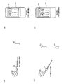
図1(A)〜図1(C)に本実施形態のリモコン装置(リモートコントロール装置)の外観構成図を示す。図1(B)、図1(C)は、各々、図1(A)のA1方向、A2方向から見た側面図である。図1(A)〜図1(C)に示すように本実施形態のリモコン装置には、撮像部10(カメラ)、モーションセンサー20、表示部30、赤外線発光部40が設けられている。具体的には、図1(C)に示すように撮像部10、赤外線発光部40は、リモコン装置の上部側面に設けられる。またモーションセンサー20は、リモコン装置の内部に設けられる。表示部30はリモコン装置の操作側の面に設けられる。
1. Configuration Example FIGS. 1A to 1C are external configuration diagrams of a remote control device (remote control device) of the present embodiment. 1B and 1C are side views as viewed from the A1 direction and the A2 direction of FIG. 1A, respectively. As shown in FIGS. 1A to 1C, the remote control device according to the present embodiment includes an imaging unit 10 (camera), a
図2に本実施形態のリモコン装置の詳細な構成ブロック図を示す。リモコン装置は撮像部10、モーションセンサー20、操作部28、表示部30、赤外線発光部40、記憶部50、情報記憶媒体60、外部I/F(インターフェース)部62、処理部100を含む。なお、本実施形態のリモコン装置は図2の構成には限定されず、これらの構成要素の一部を省略したり、他の構成要素を追加する等の種々の変形実施が可能である。
FIG. 2 shows a detailed configuration block diagram of the remote control device of the present embodiment. The remote control device includes an
撮像部10は、機器等を撮像するものであり、光学系12や撮像素子14を含む。光学系12はレンズ等により実現され、撮像素子14はCMOSセンサーやCCDセンサーなどによる実現される。
The
モーションセンサー20は、リモコン装置の動きを検出するデバイスであり、例えば加速度センサー22、ジャイロセンサー24(角速度センサー)を含む。
The
加速度センサー22としては、梁構造で支えられた可動部での位置変化を静電容量の変化として検出する静電容量型のセンサーや、ダイヤフラムの位置変化をピエゾ抵抗素子によって検出するピエゾ抵抗型のセンサーや、ガス温度分布型のセンサーなどを採用できる。ジャイロセンサー24としては、振動子が回転することによるコリオリ力から角速度を検出する振動型などの角速度センサーや、静電容量の変化や慣性力の変化から角加速度を検出する角加速度センサーなどを採用できる。
As the
加速度センサー22を用いることで、X軸、Y軸、Z軸方向でのリモコン装置の動きの加速度を検出できる。ジャイロセンサー24を用いることで、例えばX軸回り、Y軸回りでのリモコン装置の動きの角速度を検出できる。なおX軸は例えば図1(A)のリモコン装置の左右方向に沿った座標軸であり、Z軸は例えばリモコン装置の上下方向に沿った座標軸であり、Y軸はX軸及びZ軸に直交する座標軸である。なおジャイロセンサー24はZ軸回りでの角速度も検出できる3軸ジャイロセンサーであってもよい。
By using the
操作部28は、ユーザーがリモコン装置の操作情報を入力するためのものであり、例えば操作ボタンや電源ボタンなどにより実現できる。
The
表示部30は各種の画像を表示するためのものであり、例えばLCDや有機ELディスプレイなどにより実現される。例えば本実施形態では表示部30は、機器をリモコン操作するための操作画面であるリモコン操作画面を表示する。
The
表示部30は、例えばタッチパネルディスプレイにより実現することが望ましい。タッチパネルディスプレイとしては、例えば抵抗膜方式、静電容量方式、電磁誘導方式などの種々の方式のものを採用できる。なお、表示部30としてタッチパネルディスプレイを用いた場合には、操作部28の一部又は全部の機能はこのタッチパネルディスプレイにより実現されることになる。
The
赤外線発光部40(リモコン信号出力部)は、赤外線によりリモコン信号を機器に出力するものであり、例えば赤外線発光ダイオード(LED)により実現される。例えば機器を操作するためのリモコン信号は、赤外線の点灯時間と消灯時間の長さの組み合わせによりビット値が表されるパルス位相変調信号(PPM信号)等により実現できる。この場合に、自然放射されている赤外線とリモコン装置の赤外線を区別するために、赤外線発光部40は特定のキャリア周波数(例えば38〜42KHz)で変調した赤外線を発光する。
The infrared light emitting unit 40 (remote control signal output unit) outputs a remote control signal to the device by infrared rays, and is realized by, for example, an infrared light emitting diode (LED). For example, a remote control signal for operating a device can be realized by a pulse phase modulation signal (PPM signal) or the like in which a bit value is represented by a combination of the length of time for turning on and off the infrared light. In this case, the infrared
記憶部50は、リモコン装置の動作等に必要な種々の情報を記憶するものであり、例えばRAM等の半導体メモリーにより実現される。本実施形態では記憶部50は後述する登録情報や配置情報を記憶する。
The
情報記憶媒体60は、例えばメモリーカードなどの各種のメモリーメディアにより実現されるものであり、例えばリモコン装置からの脱着や装着が自在となっている。本実施形態の各部をコンピューターとして実現するためのプログラムは、この情報記憶媒体60に記憶される。
The
外部I/F部62は、外部(外部デバイス)と情報を通信するためのインターフェース処理を行うものである。外部との情報通信は有線、無線を問わない。
The external I /
処理部100は、リモコン装置の動作に必要な各種の処理を行うものである。この処理部100の機能は、各種プロセッサー(CPU等)、ASIC(ゲートアレイ等)などのハードウェアや、プログラムにより実現できる。例えば処理部100は、情報記憶媒体60に格納されるプログラムに基づいて本実施形態の種々の処理を行う。即ち情報記憶媒体60には、本実施形態の各部としてコンピューター(操作部、処理部、記憶部、出力部を備える装置)を機能させるためのプログラム(各部の処理をコンピューターに実行させるためのプログラム)が記憶される。
The
なお本実施形態のリモコン装置は専用のリモコン装置である必要はなく、例えば携帯電話機等の携帯型情報端末をリモコン装置として機能させてもよい。この場合には、本実施形態の各部を実行させるためのプログラムを携帯型情報端末において実行することで、携帯型情報端末をリモコン装置として機能させることができる。 Note that the remote control device of this embodiment does not have to be a dedicated remote control device, and a portable information terminal such as a mobile phone may function as the remote control device. In this case, the portable information terminal can be caused to function as a remote control device by executing a program for executing each part of the present embodiment on the portable information terminal.
処理部100は、認識部110、センサー情報取得部120、リモコン処理部130を含む。なお、これらの構成要素の一部を省略したり、他の構成要素を追加する等の種々の変形実施が可能である。
The
認識部(特定部)110は機器の認識処理(特定処理)を行う。例えば機器の形状認識処理やマーカー認識処理などの認識処理を行う。形状認識処理は形状認識部112が行い、マーカー認識処理はマーカー認識部114が行う。これらの認識処理の詳細については後述する。
The recognition unit (specification unit) 110 performs device recognition processing (specification processing). For example, recognition processing such as device shape recognition processing and marker recognition processing is performed. The shape recognition process is performed by the
センサー情報取得部120は、モーションセンサー20からのセンサー情報(加速度情報、角速度情報、角加速度情報等)を取得する。そして例えばセンサー情報の検出処理やセンサー情報に基づく演算処理などの種々の処理を行う。
The sensor
リモコン処理部130は、機器をリモコン操作するためのリモコン処理を行う。リモコン処理部130は、機器選択部132、リモコン信号生成部134、表示制御部136、通信処理部138を含む。機器選択部132は、リモコン操作対象機器の選択処理を行う。リモコン信号生成部134は、リモコン操作対象機器をリモコン操作するためのリモコン信号生成用情報の生成処理を行う。そして赤外線発光部40は、このリモコン信号生成用情報に基づいて、赤外線によるリモコン信号を生成して機器に送信する。なおリモコン信号生成用情報をネットワークを介してリモコン操作対象機器に送信してもよい。表示制御部136は表示部30の表示制御を行う。具体的には、リモコン操作対象機器をリモコン操作するためのリモコン操作画面を表示部30に表示する制御を行う。通信処理部138は、例えば外部I/F部62を介して外部(外部デバイス)との間で各種の情報を通信する処理を行う。なおリモコン処理部130の処理の詳細については後述する。
The remote
2.本実施形態の手法
さて、様々な機器をリモコン操作するリモコン機能を一台のリモコン装置に集約させる多機能リモコン装置については、従来より知られている。このようなリモコン装置では、ハードウェア(物理層)の違いの解消や、操作対象機器ごとの操作コマンドや制御データの違いの解消や、複数の操作対象機器の制御データの保存及び呼び出し機能を設けるなどの対応が必要になる。これらの対応を行えば、家庭内で必要なリモコン機能を一台のリモコン装置にまとめることが可能になる。
2. A method of the present embodiment A multi-function remote control device that consolidates remote control functions for remote-controlling various devices into a single remote control device has been conventionally known. Such a remote control device is provided with functions for eliminating differences in hardware (physical layer), differences in operation commands and control data for each operation target device, and storing and recalling control data for a plurality of operation target devices. It is necessary to take measures such as If these measures are taken, the remote control functions required in the home can be integrated into a single remote control device.
しかしながら、多機能リモコン装置によりこのような対応を実現するためには、複数の操作対象機器に関してリモコン装置の物理的相性を合わせ込むことが必要になる。また1つにまとめたいリモコン機能を、多機能リモコン装置に学習させる必要がある。また、多機能リモコン装置側で操作対象機器を選択し、操作キーに機能を割り当てて、目的の操作対象機器をリモコン操作するというような煩雑な操作が必要になる。従って、リモコン操作を行う際に、多くの制約をユーザーに強いる結果となってしまう。 However, in order to realize such a response by the multi-function remote control device, it is necessary to match the physical compatibility of the remote control device with respect to a plurality of operation target devices. Also, it is necessary for the multi-function remote control device to learn the remote control functions that are to be combined into one. Further, it is necessary to perform complicated operations such as selecting an operation target device on the multi-function remote control device side, assigning a function to an operation key, and operating the target operation target device by remote control. Therefore, when the remote control operation is performed, many restrictions are imposed on the user.
そこで本実施形態では、このような煩雑な操作を省き、ユーザーが直感的に使用できるように、操作対象機器をリモコン装置が選択・提示して、ユーザーの利便性を向上できるようにする。 Therefore, in the present embodiment, such a complicated operation is omitted, and the remote control device selects and presents the operation target device so that the user can use it intuitively, thereby improving the user's convenience.
具体的には本実施形態では、複数の機器(電子機器)を一台のリモコン装置で遠隔操作できるようにする。これにより、操作対象となる機器ごとにリモコン装置を取り替える必要が無くなり、ユーザーの利便性を向上できる。 Specifically, in the present embodiment, a plurality of devices (electronic devices) can be remotely operated with a single remote control device. This eliminates the need to replace the remote control device for each device to be operated, improving user convenience.
そして本実施形態では、操作対象機器を画像認識などにより自動認識し、機器に合致したリモコンコード(リモコン信号)の自動設定を行う。このようにすれば、複雑な初期設定や機能切換の操作が不要となり、ユーザーの利便性を更に向上できる。また、操作対象機器側に新たな機能を付加をすることが不要であるため、既に発売されている既存の機器にも対応が可能となり、機器側のコストアップも抑制できる。 In this embodiment, the operation target device is automatically recognized by image recognition or the like, and a remote control code (remote control signal) that matches the device is automatically set. In this way, complicated initial settings and function switching operations are not required, and user convenience can be further improved. Further, since it is not necessary to add a new function to the operation target device side, it is possible to deal with an existing device already on the market, and it is possible to suppress an increase in cost on the device side.
また本実施形態では、カメラ(撮像部)で取得した撮像画像により操作対象機器を特定し、操作対象機器のリモコン操作画面を、タッチパネルディスプレイで実現される表示部に表示する。これにより、最適な操作ボタン数と、操作機能とが関連づけされた判りやすい操作インターフェース環境をユーザーに提供できる。 In the present embodiment, an operation target device is specified by a captured image acquired by a camera (imaging unit), and a remote control operation screen of the operation target device is displayed on a display unit realized by a touch panel display. Thereby, it is possible to provide the user with an easy-to-understand operation interface environment in which the optimum number of operation buttons is associated with the operation function.
具体的には、リモコン装置に対して、既存の機器のリモコン操作機能を可能な限り搭載しておく。そして新規分については、2次元バーコードなどの識別マーカーや、有線・無線の通信や、メモリーメディアなどを用いて登録・呼び出し可能にする。また、搭載されるカメラや、ジャイロセンサー、加速度センサーなどのモーションセンサーにより、リモコン装置の現在位置からユーザーが使用することを所望する操作対象機器を、リモコン装置と操作対象機器を関連づけた配置情報(マトリックス情報)により類推選択・提示し、ユーザーの選択の利便性を向上する。 Specifically, the remote control operation function of the existing device is mounted on the remote control device as much as possible. The new portion can be registered and called using an identification marker such as a two-dimensional barcode, wired / wireless communication, memory media, and the like. In addition, by using a motion sensor such as a mounted camera, a gyro sensor, or an acceleration sensor, the operation target device that the user desires to use from the current position of the remote control device is arranged in association with the remote control device and the operation target device ( By selecting and presenting by analogy based on matrix information), the convenience of user selection is improved.
また、類推選択した操作対象機器がユーザーの望むものではない場合には、例えばリモコン装置を上下左右に振るというジェスチャー動作により、目的の操作対象機器を簡単に選択できるようにする。 If the operation target device selected by analogy is not what the user desires, the target operation target device can be easily selected by, for example, a gesture operation of shaking the remote control device up, down, left, or right.
なお、搭載カメラは、2次元バーコードなどの識別マーカーの読み込みと、リモコン装置の位置情報を得るために使用する。また加速度センサーは、重力方向と移動方向、上下左右の振りを検出するために使用する。ジャイロセンサーは、搭載カメラで認識された位置からの上下左右の振り角度を求めるために使用する。メモリーメディアは、リモコン装置に登録された登録情報や配置情報等を、PC(パソコン)上で簡単に登録・移動・削除ができるようにするために使用する。 The on-board camera is used to read an identification marker such as a two-dimensional barcode and to obtain position information of the remote control device. The acceleration sensor is used to detect the gravitational direction, the moving direction, and the up / down / left / right swing. The gyro sensor is used to obtain the vertical and horizontal swing angles from the position recognized by the on-board camera. The memory medium is used so that registration information, arrangement information, and the like registered in the remote control device can be easily registered, moved, and deleted on a PC (personal computer).
次に図3(A)〜図16(C)を用いて本実施形態の手法について更に詳細に説明する。 Next, the method of this embodiment will be described in more detail with reference to FIGS. 3 (A) to 16 (C).
本実施形態では撮像部10からの撮像画像に基づいて、機器をリモコン操作するためのリモコン処理を行う。具体的には本実施形態では、認識部110が、撮像部10からの撮像画像に対する画像認識処理により、撮像画像に映る機器の識別マーカーのマーカー認識処理を行う。そしてリモコン処理部130が、マーカー認識処理の結果に基づいて、機器をリモコン操作するためのリモコン処理を行う。
In the present embodiment, remote control processing for remote-controlling the device is performed based on the captured image from the
即ち本実施形態では機器に対して識別マーカーが取り付けられる。例えば図3(A)ではTVである機器ED1に識別マーカーMKが取り付けられ、図3(B)ではDVDプレーヤーである機器ED2に識別マーカーMKが取り付けられている。 That is, in this embodiment, an identification marker is attached to the device. For example, in FIG. 3A, the identification marker MK is attached to the device ED1 that is a TV, and in FIG. 3B, the identification marker MK is attached to the device ED2 that is a DVD player.
ここで識別マーカーMKは、各機器を識別・認識するための文字、数字又は記号などの情報を、図形又は模様等に変換して、コンピューターにより読み取り可能にした識別子である。具体的には、例えば縞模様状の線の太さによって文字、数字又は記号を表す識別子であるバーコード(2次元バーコード)などである。なお図3(A)、図3(B)では、識別マーカーMKが接着等により各機器に取り付けられているが、後述するように、機器が有する表示部に識別マーカーMKを表示するようにしてもよい。 Here, the identification marker MK is an identifier that can be read by a computer by converting information such as characters, numbers, or symbols for identifying and recognizing each device into a figure or a pattern. Specifically, for example, a bar code (two-dimensional bar code) which is an identifier representing a character, a number, or a symbol by the thickness of a striped line. In FIGS. 3A and 3B, the identification marker MK is attached to each device by bonding or the like. However, as will be described later, the identification marker MK is displayed on the display portion of the device. Also good.
そして図4(A)では、ユーザーが持つリモコン装置RMは機器ED1の方を向いており、撮像部10で撮像された撮像画像には、機器ED1の画像や、機器ED1に取り付けられた識別マーカーMKの画像が映っている。また図4(B)では、ユーザーが持つリモコン装置RMは機器ED2の方を向いており、撮像部10で撮像された撮像画像には、機器ED2の画像や、機器ED2に取り付けられた識別マーカーMKの画像が映っている。
4A, the user's remote control device RM faces the device ED1, and the captured image captured by the
この場合に認識部110は、識別マーカーMKのマーカー認識処理を行い、リモコン処理部130は、このマーカー認識処理の結果に基づいてリモコン処理を行う。例えばリモコン操作対象機器の認識処理や選択処理などを行う。
In this case, the
具体的には図4(C)に示すようにリモコン処理部130は、機器登録モードにおいて、識別マーカーMKのマーカー認識処理により得られた機器の機器情報を、登録情報として登録する。機器情報は例えば機器識別情報やリモコンコマンド情報などであり、識別マーカーMKにはこれらの情報が埋め込まれてる。例えば図2の記憶部50(リモコンデータベース)は、機器情報を含む登録情報を記憶する。そしてリモコン処理部130は、リモコン操作モードにおいて、登録情報を記憶部50から読み出すことで、リモコン操作対象機器の機器情報を取得する。そしてリモコン処理部130は、この取得された機器情報に基づいて、機器をリモコン操作するためのリモコン処理を行う。
Specifically, as shown in FIG. 4C, remote
例えば図5(A)に示すようにリモコン処理部130は、リモコン処理として、リモコン操作対象機器をリモコン操作するためのリモコン信号生成用情報の生成処理を行う。即ちリモコン処理部130は、記憶部50から読み出された機器ED1の機器情報に基づいて、機器ED1をリモコン操作するためのリモコン信号生成用情報の生成処理を行う。赤外線発光部40は、このリモコン信号生成用情報に基づいて、機器ED1用のリモコン信号を赤外線により機器ED1に送信する。これによりリモコン装置RMにより機器ED1をリモコン操作できるようになる。
For example, as shown in FIG. 5A, the remote
或いは図5(B)に示すようにリモコン処理部130は、リモコン処理として、リモコン操作対象機器をリモコン操作するためのリモコン操作画面を表示部30に表示する制御を行う。即ちリモコン処理部130は、記憶部50から読み出された機器ED1の機器情報に基づいて、機器ED1用のリモコン操作画面の表示制御を行う。例えば図5(B)では、機器ED1用の操作アイコン(操作ボタンのアイコン)が表示された機器ED1用のリモコン操作画面が表示部30に表示される。そして表示部30は例えばタッチパネルディスプレイにより構成される。従って、例えばユーザーがリモコン操作画面に表示される機器ED1用の操作アイコンにタッチすると、その操作アイコンに対応するリモコン信号が生成されて機器ED1に送信されるようになり、機器ED1のリモコン操作が可能になる。
Alternatively, as shown in FIG. 5B, the remote
一方、図5(C)ではリモコン処理部130は、記憶部50から読み出された機器ED2の機器情報に基づいて、機器ED2をリモコン操作するためのリモコン信号生成用情報の生成処理を行う。赤外線発光部40は、このリモコン信号生成用情報に基づいて、機器ED2用のリモコン信号を赤外線により機器ED2に送信する。これによりリモコン装置RMにより機器ED2をリモコン操作できるようになる。
On the other hand, in FIG. 5C, the remote
また図5(D)では、リモコン処理部130は、記憶部50から読み出された機器ED2の機器情報に基づいて、機器ED2用のリモコン操作画面の表示制御を行う。例えば図5(D)では、機器ED2用の操作アイコンが表示された機器ED2用のリモコン操作画面が表示部30に表示される。そして、例えばユーザーがリモコン操作画面に表示される機器ED2用の操作アイコンにタッチすると、その操作アイコンに対応するリモコン信号が生成されて機器ED2に送信されるようになり、機器ED2のリモコン操作が可能になる。
5D, the remote
以上のように本実施形態では、機器に取り付けられた識別マーカーのマーカー認識処理を行うことで、例えば機器登録モードにおいて各機器の機器情報を取得する。或いはリモコン操作モードにおいて、識別マーカーのマーカー認識処理によりリモコン操作対象機器を選択する。 As described above, in this embodiment, device information of each device is acquired in the device registration mode, for example, by performing marker recognition processing of the identification marker attached to the device. Alternatively, in the remote control operation mode, the remote control target device is selected by marker recognition processing of the identification marker.
このようにすれば、前述の従来技術のように赤外線LED等の情報伝達デバイスを機器側に設けなくても、機器情報の取得処理や機器の選択処理を実現することが可能になる。例えば図4(A)、図4(B)に示すように、各機器に対してその機器情報が埋め込まれた識別マーカーを取り付ける。この識別マーカーの取り付けは、機器の製造メーカーが行ってもよいし、機器を購入したユーザーが行ってもよい。ユーザーが取り付ける場合には、取り付け対象となる機器をPC等で検索し、その機器の製造メーカーのサイト等から識別マーカーの画像データ等をダウンロードする。そしてダウンロードされた画像データに基づいて識別マーカーの印刷を行い、印刷された識別マーカーを機器に貼り付ければよい。 In this way, it is possible to realize device information acquisition processing and device selection processing without providing an information transmission device such as an infrared LED on the device side as in the prior art described above. For example, as shown in FIGS. 4A and 4B, an identification marker in which the device information is embedded is attached to each device. The identification marker may be attached by the manufacturer of the device or by the user who purchased the device. When the user attaches, the device to be attached is searched with a PC or the like, and the image data of the identification marker is downloaded from the site of the manufacturer of the device. Then, the identification marker may be printed based on the downloaded image data, and the printed identification marker may be attached to the device.
そして本実施形態では、機器に取り付けられた識別マーカーを撮像部10で撮像してマーカー認識処理を行うことで、その機器の機器情報を取得する。即ち識別マーカーに埋め込まれた機器情報を取得する。
In the present embodiment, the device information of the device is acquired by imaging the identification marker attached to the device with the
従って、機器が、機器特定のための情報伝達デバイスを有しない場合にも、対応する識別マーカーを機器に取り付けることで、機器情報をリモコン装置側に伝達できるようになる。従って、機器情報の情報伝達デバイスを有しない機器に対しても対応できるようになり、ユーザーの利便性を大幅に向上できる。 Therefore, even when the device does not have an information transmission device for device identification, the device information can be transmitted to the remote control device by attaching the corresponding identification marker to the device. Accordingly, it is possible to cope with a device that does not have a device information transmission device, and the convenience of the user can be greatly improved.
図6(A)、図6(B)は、画像認識処理により機器の形状認識処理を行う手法の説明図である。例えば認識部110は、形状認識処理により機器の特徴量情報を抽出し、この特徴量情報に基づいて機器を認識する。具体的には図6(A)に示すように、撮像画像に映る機器のエッジ抽出処理を行い、機器のエッジ情報を特徴量情報として抽出する。図6(A)では機器のエッジを表す矩形の縦・横の大きさ情報などが特徴量情報になる。
FIGS. 6A and 6B are explanatory diagrams of a method for performing device shape recognition processing by image recognition processing. For example, the
そして図6(B)に示すように、リモコン処理部130は、機器登録モードにおいて、形状認識処理により得られた機器の特徴量情報を、機器の登録特徴量情報として登録する処理を行う。
Then, as shown in FIG. 6B, the remote
また認識部110は、撮像画像の画像認識処理により、機器に取り付けられた識別マーカーのマーカー認識処理も行う。そしてリモコン処理部130は、マーカー認識処理により得られた機器情報を、登録特徴量情報に関連づけて登録する。これにより記憶部50は、マーカー認識処理により得られた機器情報と、形状認識処理により得られた登録特徴量情報とが関連づけられた情報を、登録情報として記憶することになる。
The
次に、認識部110は、リモコン操作モードにおいて、撮像画像の画像認識処理により、撮像画像に映る機器の形状認識処理を行う。そしてリモコン処理部130は、リモコン操作モードにおいて、リモコン操作モードでの形状認識処理により得られた特徴量情報である機器特徴量情報と、登録特徴量情報との比較処理を行う。そしてこの比較処理により、リモコン操作対象機器の選択処理を行う。例えばリモコン操作モードにおいて、撮像部10からの撮像画像に機器ED1が映っており、この機器ED1の機器特徴量情報が、リモコンデータベースの登録特徴量情報に一致した場合には、ユーザーにより機器ED1が選択されたと判断する。
Next, the recognizing
そして図6(B)に示すように、記憶部50のリモコンデータベースには、マーカー認識処理により取得された機器の機器情報と、登録特徴量情報とが関連づけられ、登録情報として記憶されている。リモコン処理部130は、リモコン操作モードにおいて、機器特徴量情報が登録特徴量情報に一致した機器の機器情報を、記憶部50から読み出すことで、リモコン操作対象機器の機器情報を取得する。例えば、リモコン操作モードにおいて撮像画像に映る機器ED1の機器特徴量情報が登録特徴量情報に一致した場合には、この登録特徴量情報に関連づけられた機器ED1の機器情報を取得する。即ち機器ED1に取り付けられた識別マーカーのマーカー認識処理により得られた機器ED1の機器情報を、記憶部50から読み出すことで取得する。そしてリモコン処理部130は、取得された機器情報の機器識別情報やリモコンコマンド情報に基づいてリモコン処理を実行する。例えばリモコン操作対象機器をリモコン操作するためのリモコン信号生成用情報の生成処理や、リモコン操作対象機器をリモコン操作するためのリモコン操作画面を表示部30に表示する制御などを行う。
As shown in FIG. 6B, in the remote control database of the
図7(A)にリモコンデータベースのデータ構造の例を示す。リモコンデータベースには、各機器の機器情報等が登録情報として登録される。このリモコンデータベースはリモコン装置の記憶部50に記憶される。
FIG. 7A shows an example of the data structure of the remote control database. In the remote control database, device information of each device is registered as registration information. This remote control database is stored in the
機器情報は、例えば機器識別情報やリモコンコマンド情報である。機器識別情報は、機種名やメーカー名などの機器を識別するための情報である。リモコンコマンド情報は、リモコンコマンドのコマンド体系情報であり、コマンド名、機種別ボタンの定義情報、リモコン信号情報などである。また、各機器識別情報には、登録特徴量情報が関連づけられ、登録情報としてリモコンデータベースに登録される。 The device information is, for example, device identification information or remote control command information. The device identification information is information for identifying a device such as a model name or a manufacturer name. The remote control command information is command system information of a remote control command, and includes a command name, model-specific button definition information, remote control signal information, and the like. Each piece of device identification information is associated with registered feature amount information and registered in the remote control database as registration information.
リモコン装置のリモコンデータベースへの登録情報の登録手法としては種々の手法を想定できる。例えば図7(B)において、機器情報などが埋め込まれた2次元バーコード(識別マーカー)を、PC(パソコン)や携帯型情報端末の画面に表示する。そして、表示された2次元バーコードをリモコン装置の撮像部10で撮影することで、機器情報等の登録情報をリモコン装置のリモコンデータベースに登録する。或いは、PCにおいて、ネットワークを介し機器の製造メーカー等から機器情報等をダウンロードし、メモリーメディアを介してリモコン装置のリモコンデータベースに登録してもよい。この際に、後述するマトリックス化された配置情報を、PC上で編集して作成し、作成された配置情報をメモリーメディア等を介してリモコン装置のリモコンデータベースに登録してもよい。
Various methods can be envisaged as a method for registering registration information in the remote control database of the remote control device. For example, in FIG. 7B, a two-dimensional barcode (identification marker) in which device information is embedded is displayed on the screen of a PC (personal computer) or a portable information terminal. Then, the displayed two-dimensional barcode is photographed by the
さて図6(A)、図6(B)では、機器登録モードにおいて機器の形状認識処理を行うことで、機器の特徴量情報を抽出し、抽出された特徴量情報を登録特徴量情報として記憶部50に登録している。
In FIGS. 6A and 6B, device feature amount information is extracted by performing device shape recognition processing in the device registration mode, and the extracted feature amount information is stored as registered feature amount information. Registered in the
しかしながら、本実施形態はこれに限定されず、機器登録モードでの識別マーカーのマーカー認識処理により機器の特徴量情報を取得するようにしてもよい。 However, the present embodiment is not limited to this, and the feature amount information of the device may be acquired by marker recognition processing of the identification marker in the device registration mode.
具体的には図8に示すようにリモコン処理部130は、機器登録モードにおいて、機器登録モードでのマーカー認識処理により識別マーカーから取得された機器の特徴量情報を、機器の登録特徴量情報として登録する処理を行う。例えば機器に取り付けられた識別マーカーを撮像部10により撮像することで、識別マーカーから機器の特徴量情報を取得する。或いは、後述する図12に示すように携帯電話機等の携帯型情報端末の表示部に識別マーカーを表示し、この表示された識別マーカーを撮像部10により撮像することで、識別マーカーから機器の特徴量情報を取得してもよい。
Specifically, as shown in FIG. 8, in the device registration mode, the remote
そして図8に示すように記憶部50は、マーカー認識処理により得られた機器情報と、マーカー認識処理により得られた登録特徴量情報とが関連づけられた情報を、登録情報として記憶する。そして認識部110は、リモコン操作モードにおいて、撮像画像の画像認識処理により、撮像画像に映る機器の形状認識処理を行う。またリモコン処理部130は、リモコン操作モードにおいて、リモコン操作モードでの形状認識処理により得られた特徴量情報である機器特徴量情報と、登録特徴量情報との比較処理を行う。そして機器特徴量情報が登録特徴量情報に一致した機器の機器情報を記憶部50から読み出すことで、リモコン操作対象機器の機器情報を取得する。
As shown in FIG. 8, the
このように、機器登録モードにおいて、機器の形状認識処理ではなく、識別マーカーのマーカー認識処理により機器の特徴量情報を取得するようにすれば、機器登録モードでの機器の形状認識処理を行わなくて済むようになり、処理負荷を軽減できる。また、識別マーカーに機器の特徴量情報を埋め込むことで、より正確で的確な機器の特徴量情報を、登録特徴量情報として記憶部に登録することが可能になる。 As described above, in the device registration mode, if the device feature amount information is acquired by the marker recognition processing of the identification marker instead of the device shape recognition processing, the device shape recognition processing is not performed in the device registration mode. The processing load can be reduced. In addition, by embedding device feature information in the identification marker, more accurate and accurate device feature information can be registered in the storage unit as registered feature information.
また本実施形態では図2に示すように、リモコン装置RMの動きを検出するモーションセンサー20をリモコン装置RMに内蔵させている。そしてリモコン処理部130は、形状認識処理の結果と、モーションセンサー20からのセンサー情報とに基づいて、機器をリモコン操作するためのリモコン処理を行う。
In the present embodiment, as shown in FIG. 2, the
例えば後述するように、基準機器等が画像認識処理により選択された後、次の機器を選択する際には、モーションセンサー20からのセンサー情報に基づき機器を選択するようにする。例えばユーザーが所望の機器を選択するためにリモコン装置を動かすと、リモコン装置が動かされた方向をモーションセンサー20により検出し、動かされた方向に対応する方向に存在する機器を、リモコン操作対象機器として選択する。
For example, as will be described later, when the next device is selected after the reference device or the like is selected by the image recognition process, the device is selected based on the sensor information from the
また本実施形態では図9(A)に示すようにリモコン装置RMの撮像部10が機器ED1〜ED3の画像を撮像すると、表示部30は、撮像部10からの撮像画像に基づいて、複数のアイコン画像を表示してもよい。即ち複数のアイコン画像が表示された機器選択画面を表示してもよい。
In the present embodiment, as illustrated in FIG. 9A, when the
そしてリモコン処理部130は、複数のアイコン画像の中からユーザーにより選択されたアイコン画像に対応する機器を、リモコン操作対象機器として選択する。即ち、機器選択画面でのユーザーの選択操作により、機器の選択処理を行う。
Then, the remote
例えば図10(A)では、複数の機器に対応する複数のアイコン画像が表示される。このアイコン画像は、各機器を、それを象徴する絵や記号で表した画像である。例えば図9(B)のテーブルデータに示すように、ED1〜ED3等の各機器に対してIC1〜IC3等の各アイコン画像が対応づけられている。そして図9(A)のようにリモコン装置RMの撮像画像に機器ED1〜ED3が映ると、機器ED1〜ED3に対応するアイコン画像IC1〜IC3が選択され、図10(A)に示すようなアイコン画像IC1〜IC3を用いた機器選択画面が表示部30に表示される。
For example, in FIG. 10A, a plurality of icon images corresponding to a plurality of devices are displayed. This icon image is an image representing each device with a picture or symbol representing it. For example, as shown in the table data of FIG. 9B, each icon image such as IC1 to IC3 is associated with each device such as ED1 to ED3. When the devices ED1 to ED3 are reflected in the captured image of the remote control device RM as shown in FIG. 9A, the icon images IC1 to IC3 corresponding to the devices ED1 to ED3 are selected, and the icons as shown in FIG. A device selection screen using the images IC <b> 1 to IC <b> 3 is displayed on the
そして図10(B)では、ユーザーは、複数のアイコン画像の中から所望する機器のアイコン画像を、タッチ操作等により選択している。すると、リモコン処理部130は、複数のアイコン画像の中からユーザーにより選択されたアイコン画像に対応する機器を、リモコン操作対象機器として選択する。このようにすれば、画像認識処理などの負荷の重い処理を実行しなくても、ユーザーが所望する機器を簡素な処理で特定して選択できるようになる。
In FIG. 10B, the user selects an icon image of a desired device from a plurality of icon images by a touch operation or the like. Then, the remote
なお、図10(A)、図10(B)では、複数のアイコン画像が表示されているが、このようなアイコン画像ではなく、複数の機器画像を表示するようにしてもよい。そしてリモコン処理部130は、複数の機器画像の中からユーザーにより選択された機器画像に対応する機器を、リモコン操作対象機器として選択する。この機器画像は、撮像部10で撮像された機器の画像であり、例えば撮像部10の撮像画像を、そのまま表示部30に表示する。そして、この撮像画像である機器選択画面において、ユーザーが所望の機器画像をタッチ操作等で選択すると、その機器画像に対応する機器が選択されて、その機器についてのリモコン操作画面の表示制御やリモコン信号の生成処理等が行われるようになる。
Although a plurality of icon images are displayed in FIGS. 10A and 10B, a plurality of device images may be displayed instead of such icon images. Then, remote
また認識部110は、機器登録モードにおいて、撮像画像の画像認識処理により、撮像画像に映る機器の形状認識処理を行う。一方、リモコン処理部130は、機器登録モードにおいて、形状認識処理に基づき認識された複数の機器と、複数のアイコン画像又は複数の機器画像との対応づけを行う。例えば図9(B)に示すような機器とアイコン画像又は機器画像を対応づけるテーブルデータを作成する。そしてリモコン処理部130は、リモコン操作モードにおいて、図10(B)に示すようにユーザーにより選択されたアイコン画像又は機器画像に対応づけられた機器を、リモコン操作対象機器として選択してもよい。
In the device registration mode, the
このようにすれば、機器登録モードにおいてアイコン画像又は機器画像と機器とを対応づけて、リモコン操作モードでは、この対応づけの情報に基づいて、ユーザーが選択したアイコン画像又は機器画像に対応する機器を特定できるようになる。これにより図10(A)、図10(B)に示すような機器選択画面を用いた効率的な機器の選択処理を実現できるようになる。 In this way, the icon image or device image is associated with the device in the device registration mode, and the device corresponding to the icon image or device image selected by the user based on the association information in the remote control operation mode. Can be identified. As a result, an efficient device selection process using the device selection screen as shown in FIGS. 10A and 10B can be realized.
また図3(A)、図3(B)では、識別マーカーMKは機器ED1、ED2に対して接着等により取り付けられているが、本実施形態はこれに限定されない。例えば図11(A)に示すように、機器ED2が有する表示部400に識別マーカーMKを表示するようにしてもよい。この場合には認識部110は、機器ED2の表示部400が表示する識別マーカーMKのマーカー認識処理を行い、リモコン処理部130は、このマーカー認識処理の結果に基づいて、機器ED2をリモコン操作するためのリモコン処理を行う。
3A and 3B, the identification marker MK is attached to the devices ED1 and ED2 by adhesion or the like, but this embodiment is not limited to this. For example, as shown in FIG. 11A, the identification marker MK may be displayed on the
このようにすれば、識別マーカーMKを動的な識別マーカーとして使用することが可能になる。即ち、機器ED2による表示部400の表示制御により、識別マーカーMKの表示態様を動的に変化させることが可能になる。これにより、識別マーカーMKにより伝達される情報の量を増加させたり、タイムリーで適切な情報を識別マーカーMKを用いてリモコン装置に伝達することが可能になる。
In this way, the identification marker MK can be used as a dynamic identification marker. That is, the display mode of the identification marker MK can be dynamically changed by the display control of the
例えば図11(A)の機器ED2が種々の態様の識別マーカーMKを表示部400に表示することで、機器のステータス情報や操作マニュアル情報などの種々の情報を、リモコン装置側に伝達することが可能になる。即ちリモコン処理部130は、機器ED2の表示部400が表示する識別マーカーMKのマーカー認識処理の結果に基づいて、機器のステータス情報及び機器の操作マニュアル情報の少なくとも一方を取得できるようになる。そして図11(B)に示すように、取得された機器のステータス情報や操作マニュアル情報などを、リモコン装置RMの表示部30に表示できるようになる。従って、機器認識のための識別マーカーMKを、機器のステータス情報や操作マニュアル情報などの各種の情報の取得にも流用することが可能になり、ユーザーの操作インターフェース環境を向上することが可能になる。
For example, the device ED2 in FIG. 11A displays various types of identification markers MK on the
なお、前述のように識別マーカーから機器情報等を取得する場合には、機器自身の表示部に識別マーカーを表示する代わりに、図12に示すように、ユーザーが所有する携帯型情報端末(携帯電話機、携帯型ゲーム装置等)の表示部に識別マーカーを表示してもよい。そして、このように携帯型情報端末の表示部に表示された識別マーカーのマーカー認識処理を行うことで、機器の機器情報等を取得する。このようにすれば、識別マーカーを機器に取り付ける作業や、機器の表示部に識別マーカーを表示する処理などが不要にすることができる。またユーザーは、所望の機器の機器情報を取得するための識別マーカーMKの情報をネットワークを介してダウンロードし、携帯型情報端末の表示部に表示するだけで、機器情報をリモコン装置のリモコンデータベースに登録することが可能になり、ユーザーの利便性を向上できる。 As described above, when device information or the like is acquired from the identification marker, instead of displaying the identification marker on the display unit of the device itself, as shown in FIG. An identification marker may be displayed on a display unit of a telephone, a portable game device, or the like. And the apparatus information etc. of an apparatus are acquired by performing the marker recognition process of the identification marker displayed on the display part of the portable information terminal in this way. In this way, the operation of attaching the identification marker to the device, the process of displaying the identification marker on the display unit of the device, and the like can be eliminated. In addition, the user downloads the information of the identification marker MK for acquiring the device information of the desired device via the network and displays the information on the display unit of the portable information terminal, and the device information is stored in the remote control database of the remote control device. It becomes possible to register, and the convenience of the user can be improved.
また図13に示すように本実施形態では、リモコン装置RMを機器に向けると、その機器のリモコン操作画面が表示部30に表示されるようにしてもよい。
As shown in FIG. 13, in the present embodiment, when the remote control device RM is directed to a device, the remote control operation screen of the device may be displayed on the
具体的にはリモコン処理部130(表示制御部136)は、リモコン装置RMが、複数の機器のうちの第mの機器(例えば機器ED1)に対応する方向に向けられたと判断された場合には、第mの機器をリモコン操作するための第mのリモコン操作画面(機器ED1のリモコン操作画面)を、表示部30に表示する制御を行う。一方、リモコン装置RMが、複数の機器のうちの第nの機器(例えば機器ED2。なおm、nは自然数)に対応する方向に向けられたと判断された場合には、第nの機器をリモコン操作するための第nのリモコン操作画面(機器ED2のリモコン操作画面)を、表示部30に表示する制御を行う。
Specifically, remote control processing unit 130 (display control unit 136) determines that remote control device RM is directed in the direction corresponding to the m-th device (for example, device ED1) among the plurality of devices. The
例えば図13において、TVである機器ED1の方にリモコン装置RMが向けられると、TV用の操作アイコン(操作ボタンのアイコン)が表示されたTV用のリモコン操作画面が表示部30に表示される。またDVDプレーヤーである機器ED2の方にリモコン装置RMが向けられると、DVDプレーヤー用の操作アイコン等が表示されたDVDプレーヤー用のリモコン操作画面が表示部30に表示される。エアコンである機器ED3や照明器具である機器ED4に対してリモコン装置RMが向けられた場合も同様である。
For example, in FIG. 13, when the remote control device RM is directed toward the device ED1 that is a TV, a TV remote control operation screen on which a TV operation icon (operation button icon) is displayed is displayed on the
そして表示部30は例えばタッチパネルディスプレイにより構成される。従って、例えば図13に示すようにユーザーがリモコン装置RMを機器ED1(TV)の方に向け、リモコン操作画面に表示される機器ED1用の操作アイコンにタッチすると、その操作アイコンに対応するリモコン信号が生成されて機器ED1に送信される。同様にユーザーがリモコン装置RMを機器ED2(DVDプレーヤー)の方に向け、リモコン操作画面に表示される機器ED2用の操作アイコンにタッチすると、その操作アイコンに対応するリモコン信号が生成されて機器ED2に送信される。機器ED3、ED4についても同様である。
The
従って、ユーザーは、一台のリモコン装置RMを用いて複数の機器ED1〜ED4を効率的にリモコン操作できるようになる。また、操作対象機器の選択処理は、ユーザーが所望する機器にリモコン装置を向けるだけで自動的に行われるため、従来の多機能リモコン装置に比べてユーザーの利便性を格段に向上できる。 Therefore, the user can efficiently operate the plurality of devices ED1 to ED4 by remote control using one remote control device RM. In addition, since the operation target device selection process is automatically performed simply by pointing the remote control device toward the device desired by the user, the convenience of the user can be significantly improved as compared with the conventional multi-function remote control device.
また本実施形態では図2に示すように、リモコン装置RMにモーションセンサー20を内蔵させている。そして図14(A)に示すようにリモコン装置RMは、電池寿命を長くするために、静止状態(動かされずに配置されている状態)ではスリープモードに設定される。そして図14(B)に示すように、例えば加速度センサー22により、リモコン装置がユーザーの手に取られたことが感知されると、スリープモードが解除される。これにより、撮像部10、認識部110、リモコン処理部130などが起動し、システムが通常動作モードに移行する。そして、その後、撮像部10からの撮像画像やモーションセンサー20からのセンサー情報に基づいて、リモコン操作対象機器の選択処理が行われる。
In this embodiment, as shown in FIG. 2, the
具体的には、リモコン装置RMがスリープモードであるときに、モーションセンサー20からのセンサー情報に基づいてリモコン装置の動きが検出された場合に、リモコン処理部130は、動作モードをスリープモードから基準機器選択モードに移行させて、基準機器の選択を行う。リモコン処理部130は、後に詳述するように、この基準機器選択モードにおいて、第iの機器(例えば機器ED1)を、操作対象機器の選択基準となる基準機器(配置情報における配置の基準となる機器)として選択する。
Specifically, when the remote control device RM is in the sleep mode and the movement of the remote control device is detected based on the sensor information from the
次に図15(A)〜図15(C)に示すように、リモコン処理部130はモーションセンサー20からのセンサー情報に基づいてリモコン操作対象機器の選択処理を行う。
Next, as shown in FIGS. 15A to 15C, the remote
例えば複数の機器のうちの第iの機器がリモコン操作対象機器として選択された後、モーションセンサー20からのセンサー情報に基づいてリモコン装置RMの動きが検出されたとする。例えば図15(A)では、第iの機器である機器ED1が選択された後、図15(B)に示すようにモーションセンサー20によりリモコン装置RMの動きが検出されている。
For example, it is assumed that the movement of the remote control device RM is detected based on the sensor information from the
この場合にはリモコン処理部130は、第iの機器とは異なる第jの機器(i、jは自然数)を、リモコン操作対象機器として選択する。具体的には、リモコン装置RMが動かされた方向に対応する方向に存在する機器を、第jの機器として選択する。例えば図15(B)では、リモコン装置RMが右方向に動かされたことがモーションセンサー20により検出されたため、右方向に対応する方向に存在する機器ED2が、第jの機器として選択される。これにより、図13で説明したように、第jの機器用の第jのリモコン操作画面を表示部30に表示できるようになる。例えば第iの機器がTVであり、第jの機器がDVDプレーヤーである場合には、図15(A)ではTV用のリモコン操作画面が表示され、図15(B)ではDVDプレーヤー用のリモコン操作画面が表示される。
In this case, the remote
この場合に、図2の記憶部50は機器の配置情報を記憶している。そしてリモコン処理部130は、モーションセンサー20からのセンサー情報と、記憶部50に記憶される配置情報に基づいて、第jの機器(機器ED2)をリモコン操作対象機器として選択する。
In this case, the
具体的には記憶部50は、後述するマトリックス化された配置情報のように、機器の配置領域を分割した複数の区画領域の各区間領域に対して、各区画領域に配置される機器の機器情報が関連づけられた情報を、配置情報として記憶する。そしてリモコン処理部130は、複数の区画領域のうち、モーションセンサー20からのセンサー情報に基づき特定された区画領域に関連づけられた機器を、第jの機器として選択する。
Specifically, the
更に記憶部50は、機器の識別情報と機器のリモコンコマンド情報を、機器情報として記憶する。ここで機器の識別情報は機種名やメーカー名などの機器を識別・特定するための情報である。またリモコンコマンド情報は、機器のリモコン操作処理のために必要なコマンド情報であり、機器に対してコマンドを送信するリモコン信号を生成するために使用される情報である。
Further, the
また、第jの機器がリモコン操作対象機器として選択された後、モーションセンサー20からのセンサー情報に基づいてリモコン装置の動きが検出されたとする。この場合にはリモコン処理部130は、第jの機器とは異なる第kの機器(kは自然数)を、リモコン操作対象機器として選択する。
Further, it is assumed that the movement of the remote control device is detected based on the sensor information from the
例えば図15(C)では、第jの機器である機器ED2が選択された後、モーションセンサーによりリモコン装置RMの動きが検出されたため、第kの機器である機器ED3が選択される。そして図13で説明したように、第kの機器用の第kのリモコン操作画面が表示部30に表示される。例えば第kの機器がエアコンである場合には、図15(C)ではエアコン用のリモコン操作画面が表示される。
For example, in FIG. 15C, after the device ED2 that is the j-th device is selected, the motion sensor detects the movement of the remote control device RM, and thus the device ED3 that is the k-th device is selected. Then, as described in FIG. 13, the kth remote control operation screen for the kth device is displayed on the
図16(A)〜図16(C)は、機器の選択状態をユーザーに知らせる機器選択画面の例である。例えば図15(A)のように機器ED1が操作対象機器(基準機器)として選択された場合には、図16(A)に示すように、機器ED1が選択状態(選択候補)であることをユーザーに知らせる機器選択画面が表示部30に表示される。また図15(B)のように機器ED2が操作対象機器として選択された場合には、図16(B)に示すように、機器ED2が選択状態であることをユーザーに知らせる機器選択画面が表示される。また図15(C)のように機器ED3が操作対象機器として選択された場合には、図16(C)に示すように、機器ED3が選択状態であることをユーザーに知らせる機器選択画面が表示される。このようにすれば、ユーザーは、画像認識処理やリモコン装置の動き検出により、複数の機器のうちのどの機器が選択されているのかを、図16(A)〜図16(C)の機器選択画面で確認できるようになり、ユーザーの利便性を向上できる。
FIG. 16A to FIG. 16C are examples of a device selection screen that informs the user of a device selection state. For example, when the device ED1 is selected as the operation target device (reference device) as shown in FIG. 15A, the device ED1 is in the selected state (selection candidate) as shown in FIG. A device selection screen for informing the user is displayed on the
以上のように本実施形態では、例えば画像認識処理により基準機器となる機器ED1(第iの機器)が選択された後は、ユーザーがリモコン装置RMを動かすことで、機器ED2、ED3が選択されるようになる。 As described above, in the present embodiment, for example, after the device ED1 (i-th device) serving as a reference device is selected by image recognition processing, the devices ED2 and ED3 are selected by the user moving the remote controller RM. Become so.
例えば撮像部10の撮像画像内に複数の機器が映っている場合に、ユーザーがどの機器を選択しているのかを、画像認識処理だけで判別するのは難しい。この点、図15(A)〜図16(C)では、ユーザーがリモコン装置RMを動かすことで、動かした方向に対応する機器が順次選択されるようになる。従って、画像認識処理により基準機器が選択された後は、ユーザーの意思が反映されたリモコン装置RMの動きをモーションセンサー20により検出して、最終的な操作対象機器を選択できるようになる。従って、全ての機器選択を画像認識処理だけで実現する手法に比べて、少ない処理負荷で機器選択処理を実現することが可能になる。
For example, when a plurality of devices are shown in the captured image of the
3.具体的な処理例
次に本実施形態の具体的な処理例について説明する。まず、リモコン装置の操作コマンド・データなどの登録情報の登録手法と、リモコン装置の操作対象機器の選択・提示手法とジェスチャー動作対応について、順に説明する。なお、前述の物理層の差異解消については、キャリア周波数や赤外線波長が異なる場合があり得るため、必要に応じて複数の赤外LEDを準備することで、これに対応できる。或いは、これらを取り付けオプションとすることも可能である。
3. Specific Processing Example Next, a specific processing example of the present embodiment will be described. First, a registration method of registration information such as operation commands and data of the remote control device, a selection / presentation method of an operation target device of the remote control device, and gesture operation correspondence will be described in order. In addition, since the carrier frequency and the infrared wavelength may be different in the above-described physical layer difference elimination, this can be dealt with by preparing a plurality of infrared LEDs as necessary. Alternatively, these can be optional installations.
リモコン装置の操作コマンドやデータなどの登録情報の登録手法については、メモリーメディア経由で入手した機種名(広義には機器の識別情報)やコマンド体系情報(広義にはリモコンコマンド情報)を、マトリックス化された配置情報(マトリックス情報)として登録する。 For the registration method of registration information such as operation commands and data of the remote control device, the model name (equipment identification information in a broad sense) and command system information (remote control command information in a broad sense) obtained via a memory medium are matrixed Registered as placement information (matrix information).
マトリックス化された配置情報は、リモコン装置の基準点の位置に基づいて、リモコン操作対象機器の上下左右配置位置をマトリックス管理した情報である。機種名やコマンド体系情報は、リモコン装置の撮像部による2次元バーコード(識別マーカー)の読み込みなどにより入手する。 The arrangement information in the form of a matrix is information obtained by matrix management of the vertical / horizontal arrangement positions of the remote control operation target devices based on the position of the reference point of the remote control device. The model name and command system information are obtained by reading a two-dimensional barcode (identification marker) by the imaging unit of the remote control device.
即ち本実施形態のリモコン装置は、機種名とコマンド体系情報(操作情報)とがリモコンデータベースとして登録される。リモコン装置の居室での位置を使用時に認識することにより、リモコン操作対象機器のそれぞれの機器配置情報をマトリックス化された配置情報として登録しておく。 That is, in the remote control device of this embodiment, the model name and command system information (operation information) are registered as a remote control database. By recognizing the position of the remote control device in the room at the time of use, each piece of device arrangement information of the remote control operation target device is registered as matrix arrangement information.
例えば図17にマトリックス化された配置情報の例を示す。配置情報は、居室が4角形であることを前提として、前面、右側面、背面、左側面、上面、下面が設定される。前面は、基準機器が配置される基準面である。上面及び下面に対しては、リモコン装置の上下の振りによって、前面、右側面、背面、左側面のどの4面に向いていても選択可能にする。1つの面における区画領域数は図17では3×3になっている。但し、5×5等やそれ以上であっても構わない。 For example, FIG. 17 shows an example of matrix arrangement information. As the arrangement information, the front surface, the right side surface, the back surface, the left side surface, the upper surface, and the lower surface are set on the assumption that the room is a quadrangular shape. The front surface is a reference surface on which the reference device is arranged. With respect to the upper surface and the lower surface, it is possible to select any one of the front surface, right side surface, back surface, and left side surface by swinging the remote control device up and down. The number of partition areas on one surface is 3 × 3 in FIG. However, it may be 5 × 5 or more.
前面である基準面の中央に、基準機器を設定する。図17では機器ED1が基準機器になる。例えば図17では、前面には、機器ED1の他に機器ED2、ED3が配置されている。また左側面には機器ED4、ED5が配置されている。同様に右側面、背面、上面、下面にも機器ED6〜ED10が配置されている。そして、これらのED1〜ED10の各機器の区画領域にはその機器情報が関連づけられる。 Set the reference device at the center of the reference surface, which is the front surface. In FIG. 17, the device ED1 is the reference device. For example, in FIG. 17, in addition to the device ED1, devices ED2 and ED3 are arranged on the front surface. On the left side, devices ED4 and ED5 are arranged. Similarly, the devices ED6 to ED10 are arranged on the right side, the back, the top, and the bottom. And the apparatus information is linked | related with the division area of each apparatus of these ED1-ED10.
居室のほぼ中心から1.5m程度離れた位置から基準機器の選択を行うことで、リモコン装置の現在位置や向きを限定する。以降のリモコン操作対象機器の選択は、リモコン装置の上下左右の振りを、加速度センサーやジャイロセンサーから読み取り、図17の配置情報と比較して、最近傍の機器を選択・提示するようにする。 The current position and orientation of the remote control device are limited by selecting the reference device from a position approximately 1.5 m away from the center of the living room. In the subsequent selection of the target device for remote control operation, the vertical and horizontal swings of the remote control device are read from the acceleration sensor and the gyro sensor, and compared with the arrangement information shown in FIG. 17, the nearest device is selected and presented.
リモコン装置のリモコン操作対象機器の選択・提示手法とユーザーのジェスチャー動作の対応については、以下の通りである。例えば撮像部となるカメラは10万画素以上のモノクロ或いはカラーカメラにより実現される。そして撮像画像に対して画像処理を行い、基準点を検出する。例えば基準機器の形状認識等の画像認識処理を行って、基準機器が配置される基準点を検出する。 The correspondence between the selection / presentation method of the remote control target device of the remote control device and the user's gesture motion is as follows. For example, a camera serving as an imaging unit is realized by a monochrome or color camera having 100,000 pixels or more. Then, image processing is performed on the captured image to detect a reference point. For example, image recognition processing such as shape recognition of the reference device is performed to detect a reference point where the reference device is arranged.
そして検出された基準点と、リモコン装置に内蔵されている3軸加速度センサーと、2軸ジャイロセンサーにより基準点からの相対位置を演算し、身近にあるリモコン操作対象機器を1個又は数個に限定する。 Then, the relative position from the reference point is calculated by the detected reference point, the three-axis acceleration sensor built in the remote control device, and the two-axis gyro sensor, so that one or several remote control target devices are available. limit.
ユーザーによって向きを変えたリモコン装置の表示部30に、上述のように限定されたリモコン操作対象の機器のうち、ユーザーが示していると思われる可能性の最も高いものを、図16(A)〜図16(C)に示すように表示する。そのままユーザーがリモコン操作入力を行えば、選択された機器はユーザーが操作したい機器であると考えられる。
Of the remote control operation target devices limited as described above on the
もし、選択された機器が、ユーザーが操作したい機器とは異なる場合には、現在選択されている機器の上下左右のいずれかにリモコン操作対象機器が存在するはずである。従って、上下左右方向にリモコン装置を振るというユーザーのジェスチャー動作を、モーションセンサーで検出することで、最終的なリモコン操作対象機器を特定する。 If the selected device is different from the device that the user wants to operate, there should be a remote control target device on either the top, bottom, left, or right of the currently selected device. Therefore, the final remote control operation target device is specified by detecting, by the motion sensor, the user's gesture motion of shaking the remote control device in the vertical and horizontal directions.
撮像部からの撮像画像に対して画像認識処理を行うことで、複数の機器が配置されている部屋の基準となる壁面から1.5m程度離れた位置から、基準となる矩形を検出する。この矩形が操作対象機器の相対位置を決める基準点となる。そして撮像部の撮像時における基準となる矩形の変形度合いにより、部屋の中でのリモコン装置の位置を特定可能である。 By performing image recognition processing on a captured image from the imaging unit, a reference rectangle is detected from a position about 1.5 m away from a reference wall surface of a room in which a plurality of devices are arranged. This rectangle is a reference point for determining the relative position of the operation target device. Then, the position of the remote control device in the room can be specified by the degree of deformation of the rectangle serving as a reference at the time of imaging by the imaging unit.
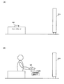
例えば図18(A)においてED1〜ED8は部屋に配置される機器である。また顔マークはユーザーの位置を表している。B1に示す中央の顔マークは、基準点を設定する場合の位置を示し、基準機器を機器ED1とした場合、壁面から約1.5m位置において機器ED1をほぼ中央に撮影する。 For example, in FIG. 18A, ED1 to ED8 are devices arranged in a room. The face mark represents the position of the user. The center face mark shown in B1 indicates the position when the reference point is set, and when the reference device is the device ED1, the device ED1 is photographed approximately at the center at a position of about 1.5 m from the wall surface.
リモコン装置の操作者であるユーザーが、図18(A)に示す顔マークの位置の何処でリモコン装置を操作するかは限定できないため、ユーザーの現在位置から、基準機器ED1(基準位置)を最初に指定する。 Since the position of the face mark shown in FIG. 18A cannot be limited by the user who is the operator of the remote control device, the reference device ED1 (reference position) is first set from the current position of the user. Is specified.
例えば図18(A)のB1に示す顔マークの位置にユーザーが居た場合には、基準機器ED1は図18(B)のC1に示すような矩形に見える。一方、B2に示す顔マークの位置にユーザーが居た場合には、基準機器ED1はC2に示すような矩形に見える。従って、基準機器ED1の矩形の形状により、ユーザーの位置を特定できる。そして、基準点が特定できれば、基準点に基づいて各操作対象機器の相対位置が特定できるので、ユーザーがリモコン装置を向けている方向等をモーションセンサーにより検出することで、操作対象機器を推定できる。 For example, when the user is at the face mark position indicated by B1 in FIG. 18A, the reference device ED1 looks like a rectangle as indicated by C1 in FIG. On the other hand, when the user is at the position of the face mark shown in B2, the reference device ED1 looks like a rectangle as shown in C2. Therefore, the position of the user can be specified by the rectangular shape of the reference device ED1. If the reference point can be specified, the relative position of each operation target device can be specified based on the reference point. Therefore, the operation target device can be estimated by detecting the direction in which the user is pointing the remote control device using a motion sensor. .
以上のように本実施形態の多機能リモコン装置では、まず最初に、使用する居室において基準点を特定する。そして、前面の上下左右方向にどのような操作対象機器が配置されているかをリモコン装置に登録する。例えば図17では機器ED1、ED2、ED3が前面に配置される機器として登録される。登録にはリモコン装置のタッチパネルディスプレイやキーパッドを活用する。或いはメモリーメディアを使用して、PC上で編集し登録することも可能である。同様の方法で、残りの5面(右側面・背面・左側面・上面・下面)について機器の登録を行う。 As described above, in the multi-function remote control device of the present embodiment, first, the reference point is specified in the room to be used. Then, what kind of operation target device is arranged in the vertical and horizontal directions on the front is registered in the remote control device. For example, in FIG. 17, the devices ED1, ED2, and ED3 are registered as devices arranged on the front surface. Registration uses the touch panel display and keypad of the remote control device. Alternatively, it is possible to edit and register on a PC using a memory medium. In the same way, the devices are registered for the remaining five surfaces (right side, back, left side, top, and bottom).
このように登録情報の登録処理後は、基準面(前面)を撮像して行う基準点の特定処理を最初に行って、リモコン装置の位置を特定した後は、ユーザーの手にリモコン装置が保持されている限りリモコン操作が可能となる。 In this way, after the registration information registration process, the reference point specifying process performed by imaging the reference plane (front surface) is first performed, and after the position of the remote control apparatus is specified, the remote control apparatus holds in the user's hand. Remote control operation is possible as long as this is done.
そして、一定時間以上、ユーザーがリモコン装置を平面に置いて操作を行わないと、基準点の位置情報が不確かになるので、基準面を撮像して行う基準点の特定処理が必要になる。基準点の特定処理については、ユーザーがリモコン装置を取り上げて基準面に向け、確認ボタンなどで入力することで確定可能である。或いは、リモコン装置を基準面に向けた後、一定時間の経過で確定するようにしてもよい。 If the user does not perform an operation with the remote control device placed on a plane for a certain period of time or longer, the position information of the reference point is uncertain, and thus a reference point specifying process performed by imaging the reference plane is required. The reference point specifying process can be determined by the user picking up the remote control device, pointing it toward the reference plane, and inputting it with a confirmation button or the like. Alternatively, after the remote control device is directed to the reference plane, it may be determined after a certain period of time.
以上のように本実施形態では、記憶部50が図17に示すような機器の配置情報を記憶する。そしてリモコン処理部130は、モーションセンサー20からのセンサー情報と、記憶部50に記憶される配置情報に基づいて、リモコン操作対象機器の選択処理を行う。ここで配置情報は、図17に示すように、機器の配置領域を分割した複数の区画領域の各区間領域に対して、各区画領域に配置される機器の機器情報が関連づけられた情報になっている。例えば図17の前面に対応する配置領域は、3×3の区画領域に分割されている。そして、真ん中の区画領域には、基準機器となる機器ED1の機器情報が関連づけられる。また機器ED1の区画領域の右側、右上側の区画領域には、各々、機器ED2、ED3の機器情報が関連づけられる。
As described above, in the present embodiment, the
そしてリモコン処理部130は、モーションセンサー20からのセンサー情報に基づき特定された区画領域に関連づけられた機器を、リモコン操作対象機器として選択する。例えば図15(A)のように基準機器となる機器ED1が選択された後、図15(B)のようにユーザーがリモコン装置を右方向に振る動作を行ったとする。すると、この時のリモコン装置の動きがモーションセンサー20(加速度センサー)により検出され、このモーションセンサー20からのセンサー情報と、図17の配置情報に基づいて、機器ED1の右側の機器ED2が選択される。
Then, the remote
その後、例えばユーザーが、リモコン装置を上方向に振る動作を行ったとする。すると、この時のリモコン装置の動きがモーションセンサー20により検出され、このモーションセンサー20からのセンサー情報と、図17の配置情報に基づいて、機器ED2の上側の機器ED3が選択されることになる。そして、このように機器ED3が選択された後、ユーザーがリモコン操作画面の表示指示操作を行うと、機器ED3のリモコン操作画面がリモコン装置の表示部30に表示されるようになる。
Thereafter, for example, it is assumed that the user performs an operation of shaking the remote control device upward. Then, the motion of the remote control device at this time is detected by the
4.動作
次に本実施形態の詳細な動作について図19〜図21のフローチャートを用いて説明する。
4). Operation Next, the detailed operation of the present embodiment will be described with reference to the flowcharts of FIGS.
図19は、マーカー認識処理により得られた登録特徴量情報と機器特徴量情報を比較することで操作対象機器を特定し、リモコン処理を行う手法の動作フローチャートである。 FIG. 19 is an operation flowchart of a technique for identifying an operation target device by comparing registered feature value information obtained by marker recognition processing and device feature value information, and performing remote control processing.
まず機器登録モードか否かを判断し、機器登録モードである場合には、撮像部10から機器の撮像画像を取得する(ステップS21、S22)。そして図8で説明したように、取得された撮像画像に基づき識別マーカーのマーカー認識処理を行い、機器情報及び機器の特徴量情報を取得する(ステップS23)。そして、マーカー認識処理により取得された特徴量情報を、登録特徴量情報として、マーカー認識処理により取得された機器情報に対応づけて、登録情報として記憶部に記憶する(ステップS24)。 First, it is determined whether or not the device registration mode is set. If the device registration mode is set, a captured image of the device is acquired from the imaging unit 10 (steps S21 and S22). Then, as described with reference to FIG. 8, the marker recognition processing of the identification marker is performed based on the acquired captured image, and device information and device feature amount information are acquired (step S <b> 23). Then, the feature amount information acquired by the marker recognition process is stored as registered feature amount information in the storage unit in association with the device information acquired by the marker recognition process (step S24).
一方、機器登録モードではなくリモコン操作モードである場合には、撮像部10から機器の撮像画像を取得する(ステップS25、S26)。そして撮像画像に基づき機器の形状認識処理を行い、機器特徴量情報を抽出する(ステップS27)。 On the other hand, when it is not the device registration mode but the remote control operation mode, a captured image of the device is acquired from the imaging unit 10 (steps S25 and S26). Then, device shape recognition processing is performed based on the captured image, and device feature amount information is extracted (step S27).
次にステップS24で記憶された登録特徴量情報を記憶部50から読み出し、ステップS27で抽出された機器特徴量情報と比較する(ステップS28)。そして機器特徴量情報が登録特徴量情報に一致した機器の機器情報を記憶部50から読み出す(ステップS29)。即ち識別マーカーのマーカー認識処理により得られた機器情報を読み出す。そして、読み出された機器情報に基づいて、リモコン信号生成処理、リモコン操作画面表示処理などのリモコン処理を実行する(ステップS30)。
Next, the registered feature value information stored in step S24 is read from the
図20は、アイコン画像が表示された機器選択画面を用いて機器を選択してリモコン処理を行う手法の動作フローチャートである。 FIG. 20 is an operation flowchart of a technique for performing remote control processing by selecting a device using a device selection screen on which an icon image is displayed.
まず機器登録モードか否かを判断し、機器登録モードである場合には、撮像部10から機器の撮像画像を取得する(ステップS41、S42)。そして撮像画像に基づきマーカー認識処理を行い、機器情報を取得する(ステップS43)。そしてマーカー認識処理により取得された機器情報を登録情報として記憶部50に記憶する(ステップS44)。
First, it is determined whether or not the device registration mode is set. If the device registration mode is set, a captured image of the device is acquired from the imaging unit 10 (steps S41 and S42). Then, marker recognition processing is performed based on the captured image, and device information is acquired (step S43). And the apparatus information acquired by the marker recognition process is memorize | stored in the memory |
一方、機器登録モードではなくリモコン操作モードである場合には、図10(A)に示すように機器のアイコン画像又は機器画像が表示された機器選択画面を表示する(ステップS45、S46)。 On the other hand, if the remote control operation mode is selected instead of the device registration mode, a device selection screen on which the device icon image or device image is displayed is displayed as shown in FIG. 10A (steps S45 and S46).
次に、図10(B)に示すようにユーザーが選択したアイコン画像又は機器画像に対応する機器の機器情報を記憶部50から読み出す(ステップS47)。即ち識別マーカーのマーカー認識処理により得られた機器情報を読み出す。そして読み出された機器情報に基づいて、リモコン信号生成処理、リモコン操作画面表示処理などのリモコン処理を実行する(ステップS48)。 Next, as shown in FIG. 10B, the device information of the device corresponding to the icon image or device image selected by the user is read from the storage unit 50 (step S47). That is, the device information obtained by the marker recognition process of the identification marker is read. Based on the read device information, remote control processing such as remote control signal generation processing and remote control operation screen display processing is executed (step S48).
図21は、モーションセンサーを用いて機器を選択してリモコン処理を行う手法の動作フローチャートである。 FIG. 21 is an operation flowchart of a technique for performing remote control processing by selecting a device using a motion sensor.
まず、図14(A)で説明したスリープモードにおいて、モーションセンサー20によりリモコン装置の動きが検出されたか否かを判断する(ステップS1、S2)。即ち加速度センサー22によりリモコン装置の静止状態からの動きが検出されたか否かを判断する。そして、動きが検出された場合には図14(B)で説明したように基準機器選択モードに移行する(ステップS3)。
First, in the sleep mode described with reference to FIG. 14A, it is determined whether or not the motion of the remote control device is detected by the motion sensor 20 (steps S1 and S2). That is, it is determined whether or not the movement of the remote control device from the stationary state is detected by the
次に、記憶部50から機器の登録情報、配置情報の読み出す(ステップS4)。即ち図7(A)で説明したような登録情報や図17で説明したような配置情報を記憶部50(リモコンデータベース)から読み出す。 Next, device registration information and arrangement information are read from the storage unit 50 (step S4). That is, the registration information as described in FIG. 7A and the arrangement information as described in FIG. 17 are read from the storage unit 50 (remote control database).
次に、撮像部10からの撮像画像に基づく機器の画像認識処理を行い、基準機器が画像認識されたか否かを判断する(ステップS5、S6)。そして基準機器が画像認識された場合には、例えばその基準機器のリモコン操作画面を表示する(ステップS7)。
Next, image recognition processing of the device based on the captured image from the
次に、モーションセンサー20によりリモコン装置の動きが検出されたか否かを判断し、リモコン装置の動きが検出された場合には、動かされた方向に対応する機器を選択する(ステップS8、S9)。例えば図15(A)で基準機器ED1が選択された後、図15(B)のようにモーションセンサー20によりリモコン装置の動きが検出されると、動かされた方向に対応する機器ED2を選択する。
Next, it is determined whether or not the motion of the remote control device is detected by the
次に、ユーザーにより表示指示操作が行われたか否かを判断する(ステップS10)。即ちリモコン操作画面の表示を指示する操作が行われたか否かを判断する。そして表示指示操作が行われた場合には、選択された機器のリモコン操作画面を表示する(ステップS11)。例えば図15(B)、図16(B)のように機器ED2が選択された状態で、ユーザーが表示指示操作を行うと、機器ED2を操作するためのリモコン操作画面が表示される。また図15(C)、図16(C)のように機器ED3が選択された状態で、ユーザーが表示指示操作を行うと、機器ED3を操作するためのリモコン操作画面が表示される。このようにすることで図13に示すように、ユーザーがリモコン装置を向けた方向に対応する機器のリモコン操作画面を表示することが可能になる。 Next, it is determined whether or not a display instruction operation has been performed by the user (step S10). That is, it is determined whether or not an operation for instructing display of the remote control operation screen has been performed. When a display instruction operation is performed, a remote control operation screen for the selected device is displayed (step S11). For example, when the user performs a display instruction operation with the device ED2 selected as shown in FIGS. 15B and 16B, a remote control operation screen for operating the device ED2 is displayed. Further, when the user performs a display instruction operation in a state where the device ED3 is selected as shown in FIGS. 15C and 16C, a remote control operation screen for operating the device ED3 is displayed. By doing so, as shown in FIG. 13, it becomes possible to display the remote control operation screen of the device corresponding to the direction in which the user points the remote control device.
なお、以上のように本実施形態について詳細に説明したが、本発明の新規事項および効果から実体的に逸脱しない多くの変形が可能であることは当業者には容易に理解できるであろう。従って、このような変形例はすべて本発明の範囲に含まれるものとする。例えば、明細書又は図面において、少なくとも一度、より広義または同義な異なる用語と共に記載された用語は、明細書又は図面のいかなる箇所においても、その異なる用語に置き換えることができる。またリモコン装置の構成、動作も本実施形態で説明したものに限定されず、種々の変形実施が可能である。 Although the present embodiment has been described in detail as described above, it will be easily understood by those skilled in the art that many modifications can be made without departing from the novel matters and effects of the present invention. Accordingly, all such modifications are intended to be included in the scope of the present invention. For example, a term described at least once together with a different term having a broader meaning or the same meaning in the specification or the drawings can be replaced with the different term in any part of the specification or the drawings. The configuration and operation of the remote control device are not limited to those described in the present embodiment, and various modifications can be made.
RM リモコン装置、ED1〜ED10 機器、MK 識別マーカー、
10 撮像部、12 光学系、14 撮像素子、20 モーションセンサー、
22 加速度センサー、24 ジャイロセンサー、28 操作部、30 表示部、
40 赤外線発光部、50 記憶部、60 情報記憶媒体、62 外部I/F部、
100 処理部、110 認識部、112 形状認識部、114 マーカー認識部、
120 センサー情報取得部、130 リモコン処理部、132 機器選択部、
134 リモコン信号生成部、136 表示制御部、138 通信処理部
RM remote control device, ED1-ED10 equipment, MK identification marker,
10 imaging unit, 12 optical system, 14 imaging element, 20 motion sensor,
22 acceleration sensor, 24 gyro sensor, 28 operation unit, 30 display unit,
40 infrared light emitting section, 50 storage section, 60 information storage medium, 62 external I / F section,
100 processing unit, 110 recognition unit, 112 shape recognition unit, 114 marker recognition unit,
120 sensor information acquisition unit, 130 remote control processing unit, 132 device selection unit,
134 Remote control signal generator, 136 Display controller, 138 Communication processor
Claims (14)
機器の認識処理を行う認識部と、
機器をリモコン操作するためのリモコン処理を行うリモコン処理部と、
を含み、
前記認識部は、
前記撮像画像の画像認識処理により、前記撮像画像に映る機器の識別マーカーのマーカー認識処理を行い、
前記リモコン処理部は、
前記マーカー認識処理の結果に基づいて、機器をリモコン操作するためのリモコン処理を行うことを特徴とするリモコン装置。 An imaging unit for imaging the device;
A recognition unit that performs device recognition processing;
A remote control processing unit for performing remote control processing for remote control of the device;
Including
The recognition unit
By performing image recognition processing of the captured image, marker recognition processing of an identification marker of a device reflected in the captured image is performed,
The remote control processing unit
A remote control device for performing a remote control process for remote-controlling a device based on a result of the marker recognition process.
前記リモコン処理部は、
機器登録モードにおいて、前記マーカー認識処理により得られた機器の機器情報を、登録情報として登録することを特徴とするリモコン装置。 In claim 1,
The remote control processing unit
In the device registration mode, the device information of the device obtained by the marker recognition process is registered as registration information.
前記機器情報を含む前記登録情報を記憶する記憶部を含み、
前記リモコン処理部は、
リモコン操作モードにおいて、前記登録情報を前記記憶部から読み出すことで、リモコン操作対象機器の前記機器情報を取得することを特徴とするリモコン装置。 In claim 2,
A storage unit for storing the registration information including the device information;
The remote control processing unit
In the remote control operation mode, the device information of a remote control operation target device is acquired by reading the registration information from the storage unit.
前記認識部は、
前記機器登録モードにおいて、前記撮像画像の画像認識処理により、前記撮像画像に映る機器の形状認識処理を行い、
前記リモコン処理部は、
前記機器登録モードにおいて、前記機器登録モードでの形状認識処理により得られた機器の特徴量情報を、機器の登録特徴量情報として登録する処理を行い、
前記記憶部は、
前記マーカー認識処理により得られた前記機器情報と、前記形状認識処理により得られた前記登録特徴量情報とが関連づけられた情報を、前記登録情報として記憶し、
前記認識部は、
前記リモコン操作モードにおいて、前記撮像画像の画像認識処理により、前記撮像画像に映る機器の形状認識処理を行い、
前記リモコン処理部は、
前記リモコン操作モードにおいて、前記リモコン操作モードでの前記形状認識処理により得られた特徴量情報である機器特徴量情報と、前記登録特徴量情報との比較処理を行い、前記機器特徴量情報が前記登録特徴量情報に一致した機器の前記機器情報を前記記憶部から読み出すことで、リモコン操作対象機器の前記機器情報を取得することを特徴とするリモコン装置。 In claim 3,
The recognition unit
In the device registration mode, by performing image recognition processing of the captured image, perform shape recognition processing of the device reflected in the captured image,
The remote control processing unit
In the device registration mode, the device feature amount information obtained by the shape recognition process in the device registration mode is registered as device feature information.
The storage unit
Information associating the device information obtained by the marker recognition process with the registered feature amount information obtained by the shape recognition process is stored as the registration information,
The recognition unit
In the remote control operation mode, by performing image recognition processing of the captured image, performing shape recognition processing of the device reflected in the captured image,
The remote control processing unit
In the remote control operation mode, a comparison process is performed between device feature amount information, which is feature amount information obtained by the shape recognition process in the remote control operation mode, and the registered feature amount information, and the device feature amount information is A remote control device, wherein the device information of a remote control operation target device is acquired by reading out the device information of a device that matches registered feature amount information from the storage unit.
前記リモコン処理部は、
前記機器登録モードにおいて、前記機器登録モードでの前記マーカー認識処理により前記識別マーカーから取得された機器の特徴量情報を、機器の登録特徴量情報として登録する処理を行い、
前記記憶部は、
前記マーカー認識処理により得られた前記機器情報と、前記マーカー認識処理により得られた前記登録特徴量情報とが関連づけられた情報を、前記登録情報として記憶し、
前記認識部は、
前記リモコン操作モードにおいて、前記撮像画像の画像認識処理により、前記撮像画像に映る機器の形状認識処理を行い、
前記リモコン処理部は、
前記リモコン操作モードにおいて、前記リモコン操作モードでの前記形状認識処理により得られた特徴量情報である機器特徴量情報と、前記登録特徴量情報との比較処理を行い、前記機器特徴量情報が前記登録特徴量情報に一致した機器の前記機器情報を前記記憶部から読み出すことで、リモコン操作対象機器の前記機器情報を取得することを特徴とするリモコン装置。 In claim 3,
The remote control processing unit
In the device registration mode, the device feature amount information acquired from the identification marker by the marker recognition process in the device registration mode is registered as device feature information.
The storage unit
Information associating the device information obtained by the marker recognition process with the registered feature amount information obtained by the marker recognition process is stored as the registration information,
The recognition unit
In the remote control operation mode, by performing image recognition processing of the captured image, performing shape recognition processing of the device reflected in the captured image,
The remote control processing unit
In the remote control operation mode, a comparison process is performed between device feature amount information, which is feature amount information obtained by the shape recognition process in the remote control operation mode, and the registered feature amount information, and the device feature amount information is A remote control device, wherein the device information of a remote control operation target device is acquired by reading out the device information of a device that matches registered feature amount information from the storage unit.
リモコン装置の動きを検出するモーションセンサーを含み、
前記リモコン処理部は、
前記形状認識処理の結果と前記モーションセンサーからのセンサー情報とに基づいて、機器をリモコン操作するためのリモコン処理を行うことを特徴とするリモコン装置。 In claim 4 or 5,
Including a motion sensor to detect the movement of the remote control device,
The remote control processing unit
A remote control device for performing remote control processing for remote-controlling a device based on a result of the shape recognition processing and sensor information from the motion sensor.
複数の機器に対応する複数のアイコン画像又は前記複数の機器の複数の機器画像を表示する表示部を含み、
前記リモコン処理部は、
前記複数のアイコン画像又は前記複数の機器画像の中からユーザーにより選択されたアイコン画像又は機器画像に対応する機器を、リモコン操作対象機器として選択することを特徴とするリモコン装置。 In claim 3,
A display unit for displaying a plurality of icon images corresponding to a plurality of devices or a plurality of device images of the plurality of devices;
The remote control processing unit
A remote control device, wherein a device corresponding to an icon image or a device image selected by a user from the plurality of icon images or the plurality of device images is selected as a remote control operation target device.
前記認識部は、
機器に取り付けられた前記識別マーカーの前記マーカー認識処理を行うことを特徴とするリモコン装置。 In any one of Claims 1 thru | or 7,
The recognition unit
A remote control device that performs the marker recognition processing of the identification marker attached to a device.
前記認識部は、
機器の表示部が表示する前記識別マーカーの前記マーカー認識処理を行うことを特徴とするリモコン装置。 In any one of Claims 1 thru | or 7,
The recognition unit
A remote control device that performs the marker recognition processing of the identification marker displayed on a display unit of a device.
前記リモコン処理部は、
機器の表示部が表示する前記識別マーカーの前記マーカー認識処理の結果に基づいて、機器のステータス情報及び機器の操作マニュアル情報の少なくとも一方を取得することを特徴とするリモコン装置。 In claim 9,
The remote control processing unit
A remote control device that acquires at least one of device status information and device operation manual information based on a result of the marker recognition processing of the identification marker displayed by a display unit of the device.
前記リモコン処理部は、
前記リモコン処理として、リモコン操作対象機器をリモコン操作するためのリモコン信号生成用情報の生成処理を行うことを特徴とするリモコン装置。 In any one of Claims 1 thru | or 10.
The remote control processing unit
As the remote control process, a remote control apparatus generates a remote control signal generation information for operating a remote control target device by remote control.
前記リモコン処理部は、
前記リモコン処理として、リモコン操作対象機器をリモコン操作するためのリモコン操作画面を表示部に表示する制御を行うことを特徴とするリモコン装置。 In any one of Claims 1 thru | or 11,
The remote control processing unit
As the remote control process, a remote control apparatus is provided that performs control to display a remote control operation screen for performing remote control operation on a remote control target device on a display unit.
前記リモコン処理部は、
リモコン装置が、複数の機器のうちの第mの機器に対応する方向に向けられたと判断された場合には、前記第mの機器をリモコン操作するための第mのリモコン操作画面を、前記表示部に表示する制御を行い、
リモコン装置が、前記複数の機器のうちの第nの機器(m、nは自然数)に対応する方向に向けられたと判断された場合には、前記第nの機器をリモコン操作するための第nのリモコン操作画面を、前記表示部に表示する制御を行うことを特徴とするリモコン装置。 In claim 12,
The remote control processing unit
When it is determined that the remote control device is directed in the direction corresponding to the m-th device among the plurality of devices, the display displays the m-th remote control operation screen for operating the m-th device by remote control. Control to display in the
When it is determined that the remote control device is directed in the direction corresponding to the n-th device (m and n are natural numbers) among the plurality of devices, the n-th device for remote-controlling the n-th device A remote control device for controlling the remote control operation screen to be displayed on the display unit.
機器の認識処理を行う認識部と、
機器をリモコン操作するためのリモコン処理を行うリモコン処理部として、
コンピューターを機能させ、
前記認識部は、
前記撮像画像の画像認識処理により、前記撮像画像に映る機器の識別マーカーのマーカー認識処理を行い、
前記リモコン処理部は、
前記マーカー認識処理の結果に基づいて、機器をリモコン操作するためのリモコン処理を行うことを特徴とするプログラム。 An imaging unit for imaging the device;
A recognition unit that performs device recognition processing;
As a remote control processing unit that performs remote control processing for remote control of equipment,
Make the computer work,
The recognition unit
By performing image recognition processing of the captured image, marker recognition processing of an identification marker of a device reflected in the captured image is performed,
The remote control processing unit
A program for performing remote control processing for remote-controlling a device based on a result of the marker recognition processing.
Priority Applications (1)
| Application Number | Priority Date | Filing Date | Title |
|---|---|---|---|
| JP2011014865A JP2012156836A (en) | 2011-01-27 | 2011-01-27 | Remote controller and program |
Applications Claiming Priority (1)
| Application Number | Priority Date | Filing Date | Title |
|---|---|---|---|
| JP2011014865A JP2012156836A (en) | 2011-01-27 | 2011-01-27 | Remote controller and program |
Publications (1)
| Publication Number | Publication Date |
|---|---|
| JP2012156836A true JP2012156836A (en) | 2012-08-16 |
Family
ID=46838097
Family Applications (1)
| Application Number | Title | Priority Date | Filing Date |
|---|---|---|---|
| JP2011014865A Withdrawn JP2012156836A (en) | 2011-01-27 | 2011-01-27 | Remote controller and program |
Country Status (1)
| Country | Link |
|---|---|
| JP (1) | JP2012156836A (en) |
Cited By (5)
| Publication number | Priority date | Publication date | Assignee | Title |
|---|---|---|---|---|
| JP2014078771A (en) * | 2012-10-08 | 2014-05-01 | I-O Data Device Inc | Video communication system, mobile communication terminal, video communication terminal, video communication program, mobile communication terminal program, and video communication terminal program |
| JP2016511992A (en) * | 2014-01-16 | 2016-04-21 | 加一聯創電子科技有限公司1More Inc. | Internet of Things Control Method, Terminal and Controlled Device |
| JP2016144065A (en) * | 2015-02-03 | 2016-08-08 | シャープ株式会社 | Control terminal device |
| JPWO2016002050A1 (en) * | 2014-07-03 | 2017-04-27 | 三菱電機株式会社 | Control system, terminal, information setting method and program |
| JP2021524119A (en) * | 2018-05-09 | 2021-09-09 | 北京外号信息技術有限公司Beijing Whyhow Information Technology Co., Ltd | Information device interaction methods and systems based on optical labels |
Citations (6)
| Publication number | Priority date | Publication date | Assignee | Title |
|---|---|---|---|---|
| JP2005065118A (en) * | 2003-08-19 | 2005-03-10 | Hitachi Ltd | Mobile terminal with remote control function and remote control server |
| JP2005513941A (en) * | 2001-12-28 | 2005-05-12 | コーニンクレッカ フィリップス エレクトロニクス エヌ ヴィ | Universal remote control device with automatic instrument identification and programming |
| JP2005176242A (en) * | 2003-12-15 | 2005-06-30 | Dainippon Printing Co Ltd | Program picture recording reservation method, portable terminal, and printed matter |
| JP2006166295A (en) * | 2004-12-10 | 2006-06-22 | Seiko Epson Corp | Control system, controlled device suited to the system and remote control device |
| JP2009055572A (en) * | 2007-08-29 | 2009-03-12 | Sharp Corp | Remote controlling system, portable communicating terminal device, remote controlling remote-control device, remote controlling method, and program |
| WO2009063628A1 (en) * | 2007-11-15 | 2009-05-22 | Panasonic Corporation | Multi-remote control device, multi-remote control method, and integrated circuit |
-
2011
- 2011-01-27 JP JP2011014865A patent/JP2012156836A/en not_active Withdrawn
Patent Citations (6)
| Publication number | Priority date | Publication date | Assignee | Title |
|---|---|---|---|---|
| JP2005513941A (en) * | 2001-12-28 | 2005-05-12 | コーニンクレッカ フィリップス エレクトロニクス エヌ ヴィ | Universal remote control device with automatic instrument identification and programming |
| JP2005065118A (en) * | 2003-08-19 | 2005-03-10 | Hitachi Ltd | Mobile terminal with remote control function and remote control server |
| JP2005176242A (en) * | 2003-12-15 | 2005-06-30 | Dainippon Printing Co Ltd | Program picture recording reservation method, portable terminal, and printed matter |
| JP2006166295A (en) * | 2004-12-10 | 2006-06-22 | Seiko Epson Corp | Control system, controlled device suited to the system and remote control device |
| JP2009055572A (en) * | 2007-08-29 | 2009-03-12 | Sharp Corp | Remote controlling system, portable communicating terminal device, remote controlling remote-control device, remote controlling method, and program |
| WO2009063628A1 (en) * | 2007-11-15 | 2009-05-22 | Panasonic Corporation | Multi-remote control device, multi-remote control method, and integrated circuit |
Cited By (7)
| Publication number | Priority date | Publication date | Assignee | Title |
|---|---|---|---|---|
| JP2014078771A (en) * | 2012-10-08 | 2014-05-01 | I-O Data Device Inc | Video communication system, mobile communication terminal, video communication terminal, video communication program, mobile communication terminal program, and video communication terminal program |
| JP2016511992A (en) * | 2014-01-16 | 2016-04-21 | 加一聯創電子科技有限公司1More Inc. | Internet of Things Control Method, Terminal and Controlled Device |
| JPWO2016002050A1 (en) * | 2014-07-03 | 2017-04-27 | 三菱電機株式会社 | Control system, terminal, information setting method and program |
| US9779275B2 (en) | 2014-07-03 | 2017-10-03 | Mitsubishi Electric Corporation | Control system, terminal, information setting method, and program |
| JP2016144065A (en) * | 2015-02-03 | 2016-08-08 | シャープ株式会社 | Control terminal device |
| JP2021524119A (en) * | 2018-05-09 | 2021-09-09 | 北京外号信息技術有限公司Beijing Whyhow Information Technology Co., Ltd | Information device interaction methods and systems based on optical labels |
| JP7150980B2 (en) | 2018-05-09 | 2022-10-11 | 北京外号信息技術有限公司 | Information device interaction method and system based on optical label |
Similar Documents
| Publication | Publication Date | Title |
|---|---|---|
| US20210383551A1 (en) | Fiducial marker patterns, their automatic detection in images, and applications thereof | |
| CN103916875B (en) | Management and planning system based on WIFI wireless networks multiclass control terminal | |
| KR100533839B1 (en) | Control device of electronic devices based on motion | |
| KR20240009999A (en) | Beacons for localization and content delivery to wearable devices | |
| CN110456782B (en) | Control device and control method | |
| US8971629B2 (en) | User interface system based on pointing device | |
| US9179182B2 (en) | Interactive multi-display control systems | |
| RU2654155C2 (en) | Interaction detection wearable control device | |
| US20040121725A1 (en) | Remote control device | |
| JP2012156836A (en) | Remote controller and program | |
| JP6104143B2 (en) | Device control system and device control method | |
| CN113728293A (en) | System and interface for location-based device control | |
| KR20220063205A (en) | Augmented reality for setting up an internet connection | |
| US10936184B2 (en) | Display apparatus and controlling method thereof | |
| JP2012156834A (en) | Remote controller and program | |
| JP2016087106A (en) | Cleaning support device and cleaner | |
| JP2020126448A (en) | Electronic apparatus, control method, and control program | |
| JP2008511877A (en) | Device control method | |
| JP2012156835A (en) | Remote controller and program | |
| JP2014139745A (en) | Equipment management system, equipment management device, equipment management method and program | |
| KR101964192B1 (en) | Smart table apparatus for simulation | |
| CN107924272B (en) | Information processing apparatus, information processing method, and program | |
| JP5659787B2 (en) | Operation environment model construction system and operation environment model construction method | |
| WO2020244577A1 (en) | Location-based interaction method and interactive system | |
| JP5115496B2 (en) | Content remote control system and remote control terminal |
Legal Events
| Date | Code | Title | Description |
|---|---|---|---|
| A621 | Written request for application examination |
Free format text: JAPANESE INTERMEDIATE CODE: A621 Effective date: 20140108 |
|
| A977 | Report on retrieval |
Free format text: JAPANESE INTERMEDIATE CODE: A971007 Effective date: 20140627 |
|
| A131 | Notification of reasons for refusal |
Free format text: JAPANESE INTERMEDIATE CODE: A131 Effective date: 20140701 |
|
| A761 | Written withdrawal of application |
Free format text: JAPANESE INTERMEDIATE CODE: A761 Effective date: 20140827 |