JP2012155444A - Electronic equipment - Google Patents
Electronic equipment Download PDFInfo
- Publication number
- JP2012155444A JP2012155444A JP2011012800A JP2011012800A JP2012155444A JP 2012155444 A JP2012155444 A JP 2012155444A JP 2011012800 A JP2011012800 A JP 2011012800A JP 2011012800 A JP2011012800 A JP 2011012800A JP 2012155444 A JP2012155444 A JP 2012155444A
- Authority
- JP
- Japan
- Prior art keywords
- microcomputer
- sub
- electronic device
- main microcomputer
- control program
- Prior art date
- Legal status (The legal status is an assumption and is not a legal conclusion. Google has not performed a legal analysis and makes no representation as to the accuracy of the status listed.)
- Pending
Links
Images

Classifications
-
- G—PHYSICS
- G06—COMPUTING; CALCULATING OR COUNTING
- G06F—ELECTRIC DIGITAL DATA PROCESSING
- G06F1/00—Details not covered by groups G06F3/00 - G06F13/00 and G06F21/00
- G06F1/26—Power supply means, e.g. regulation thereof
- G06F1/32—Means for saving power
- G06F1/3203—Power management, i.e. event-based initiation of a power-saving mode
- G06F1/3234—Power saving characterised by the action undertaken
- G06F1/3293—Power saving characterised by the action undertaken by switching to a less power-consuming processor, e.g. sub-CPU
-
- Y—GENERAL TAGGING OF NEW TECHNOLOGICAL DEVELOPMENTS; GENERAL TAGGING OF CROSS-SECTIONAL TECHNOLOGIES SPANNING OVER SEVERAL SECTIONS OF THE IPC; TECHNICAL SUBJECTS COVERED BY FORMER USPC CROSS-REFERENCE ART COLLECTIONS [XRACs] AND DIGESTS
- Y02—TECHNOLOGIES OR APPLICATIONS FOR MITIGATION OR ADAPTATION AGAINST CLIMATE CHANGE
- Y02D—CLIMATE CHANGE MITIGATION TECHNOLOGIES IN INFORMATION AND COMMUNICATION TECHNOLOGIES [ICT], I.E. INFORMATION AND COMMUNICATION TECHNOLOGIES AIMING AT THE REDUCTION OF THEIR OWN ENERGY USE
- Y02D10/00—Energy efficient computing, e.g. low power processors, power management or thermal management
Abstract
Description
本発明は、複数の制御部を備える電子装置に関する。 The present invention relates to an electronic device including a plurality of control units.
電子装置の主たる機能を制御するための制御部(メインマイコン)と、それ以外の機能を制御するための制御部(サブマイコン)とを備える電子装置が知られている(特許文献1,2参照。)。サブマイコンは、例えば、リモートコントロール装置や操作パネルを介した外部からの操作に応じた処理や製品本体に設けられたLEDの発光制御などを、製品の仕様に応じて行なう。電子装置(例えば、DVDやブルーレイディスク(BD)等のメディアの再生装置)は、その製品のモデルや仕向け地の違いによって仕様が異なるため、仕様の違いに応じてサブマイコンの働きも異ならせる必要がある(サブマイコンは自己が搭載されている製品の仕様に合った働きをする必要がある)。従来では、製品の仕様毎に、サブマイコンの回路を構成する所定の複数のポートを回路構成上プルアップ或いはプルダウンすることで当該各ポートの電位をハイレベル又はローレベルに設定し、これら各ポートのレベルの設定状況(ハイレベル/ローレベルの組合せ)に応じてサブマイコンは自己の仕様を認識、選択するようにしていた。 2. Description of the Related Art An electronic device is known that includes a control unit (main microcomputer) for controlling main functions of an electronic device and a control unit (sub-microcomputer) for controlling other functions (see Patent Documents 1 and 2). .) The sub-microcomputer performs, for example, processing according to an external operation via a remote control device or an operation panel, light emission control of an LED provided in the product body, and the like according to the product specifications. Electronic devices (for example, media playback devices such as DVDs and Blu-ray Discs (BD)) have different specifications depending on the product models and destinations, so the sub-microcomputer must function differently depending on the specifications. (The sub-microcomputer needs to work according to the specifications of the product on which it is mounted.) Conventionally, for each product specification, the potential of each port is set to high level or low level by pulling up or pulling down a predetermined plurality of ports constituting the circuit of the sub microcomputer in the circuit configuration. The sub-microcomputer recognizes and selects its own specifications in accordance with the level setting status (high level / low level combination).
また上記文献1では、電子装置のシステムを制御するメインマイコンと、パネルキーの入力信号を処理するサブマイコンとを有する電子装置であって、メインマイコンは、メインマイコンが備えるROMに書き込まれている電子装置のモデル仕様又は仕向け先仕様に基づいて、当該ROM内のキー定義値テーブルにおける各キーコードを、メインマイコンが備える第1のRAM内のキーテーブルにおける操作パネルの各パネルキーに対応したアドレスに格納し、第1のRAMに格納したキーテーブルのキーコードをサブマイコンに転送し、サブマイコンは、当該転送されたキーテーブルのキーコードを、サブマイコンが備える第2のRAM内のキーテーブルにおける操作パネルの各パネルキーに対応したアドレスに格納し、サブマイコンは、操作パネルのいずれかのパネルキーが操作された場合、操作されたパネルキーに対応した第2のRAMのキーテーブルのアドレスに格納されたキーコードをメインマイコンに送信する構成を採用していた。 Further, in the above-mentioned document 1, an electronic device having a main microcomputer that controls the system of the electronic device and a sub-microcomputer that processes panel key input signals, the main microcomputer is written in a ROM included in the main microcomputer. Based on the model specification or destination specification of the electronic device, each key code in the key definition value table in the ROM corresponds to each panel key of the operation panel in the key table in the first RAM provided in the main microcomputer. And the key code of the key table stored in the first RAM is transferred to the sub-microcomputer, and the sub-microcomputer uses the key code of the transferred key table in the second RAM included in the sub-microcomputer. The sub microcomputer is stored in the address corresponding to each panel key of the operation panel in If any of the panel keys work panel is operated, it had adopted a configuration which transmits stored in the address of the second RAM key table corresponding to the operated panel keys a key code to the main microprocessor.
従来のように、電子装置の仕様毎にサブマイコンの上記各ポートのレベル設定を行なう作業は、電子装置の仕様毎にハードウェア構成(抵抗等の回路素子を含む回路構成)を変更することになるため煩雑であった。また、上記文献1では、メインマイコンの第1のRAMに格納したキーテーブルのキーコードをサブマイコンに転送してサブマイコンの第2のRAM内のキーテーブルに格納する構成を採用しているが、このようにサブマイコンの設定を製品の仕様に合わせる(文献1の場合、仕様に応じた操作パネルの各パネルキーと各キーコードとの対応関係を認識させる)構成としては、さらなる改善の余地があった。 As in the prior art, the task of setting the level of each port of the sub-microcomputer for each electronic device specification is to change the hardware configuration (circuit configuration including circuit elements such as resistors) for each electronic device specification. Therefore, it was complicated. Further, in the above-mentioned document 1, a configuration is adopted in which the key code of the key table stored in the first RAM of the main microcomputer is transferred to the sub microcomputer and stored in the key table in the second RAM of the sub microcomputer. In this way, the configuration of the sub-microcomputer is matched to the product specifications (in the case of Document 1, the correspondence between each panel key of the operation panel and each key code according to the specification is recognized), there is room for further improvement was there.
本発明は少なくとも上記課題を解決するためになされたものであり、ハードウェアの変更や複雑な処理を要することなく、簡易かつ確実にサブマイコンの機能設定(仕様の選択)を行なうことが可能な電子装置を提供する。 The present invention has been made in order to solve at least the above-described problems, and can easily and surely perform function setting (selection of specifications) of a sub-microcomputer without requiring hardware change or complicated processing. An electronic device is provided.
本発明の態様の一つは、電子装置の所定機能を制御するメインマイコンと、少なくとも外部からの操作に応じた処理を制御プログラムに従って実行するサブマイコンとを有する電子装置であって、サブマイコンは、電子装置の異なる各仕様にそれぞれ対応した複数の制御プログラムを格納した第1メモリーを備え、メインマイコンは、電子装置の仕様を特定する仕様情報を格納した第2メモリーを備え、当該第2メモリーに格納した仕様情報に基づく仕様の選択指示をサブマイコンに送信し、サブマイコンは、上記第1メモリーに格納した複数の制御プログラムの中から、上記送信された選択指示が示す仕様に対応する制御プログラムを選択し、当該選択した制御プログラムに従った処理を実行する、構成としてある。 One aspect of the present invention is an electronic apparatus having a main microcomputer that controls a predetermined function of the electronic apparatus, and a sub-microcomputer that executes at least processing according to an operation from the outside according to a control program. A first memory storing a plurality of control programs corresponding to different specifications of the electronic device, and the main microcomputer includes a second memory storing specification information for specifying the specifications of the electronic device. A specification selection instruction based on the specification information stored in is transmitted to the sub-microcomputer, and the sub-microcomputer controls the control corresponding to the specification indicated by the transmitted selection instruction from among the plurality of control programs stored in the first memory. The program is selected, and processing according to the selected control program is executed.
当該構成によれば、サブマイコンの第1メモリーには予め電子装置の仕様毎に対応した複数の制御プログラムが格納されており、メインマイコンから仕様の選択指示が送信されたときに、サブマイコンは当該選択指示に対応する制御プログラムを選択する。そのため、サブマイコンは極めて容易に電子装置の仕様に合った制御プログラムを選択することができ、以後、当該選択した制御プログラムの下で当該仕様に合った正しい処理を実行することができる。 According to this configuration, a plurality of control programs corresponding to the specifications of the electronic device are stored in advance in the first memory of the sub-microcomputer. When the specification selection instruction is transmitted from the main microcomputer, the sub-microcomputer A control program corresponding to the selection instruction is selected. Therefore, the sub-microcomputer can very easily select a control program that meets the specifications of the electronic device, and can subsequently execute correct processing that meets the specifications under the selected control program.
本発明の実施形態としては、電子装置と外部電源とが接続した場合、サブマイコンが駆動状態となった後にメインマイコンが駆動状態となり、駆動状態となったメインマイコンとサブマイコンとの間での通信が確立した後にメインマイコンは上記選択指示をサブマイコンに送信し、メインマイコンは当該送信後に駆動停止状態へ移行する構成としてもよい。
また本発明の実施形態としては、サブマイコンは、メインマイコンからの上記選択指示に応じて制御プログラムを選択する前に、電子装置の仕様に関わらず指示内容が予め決められている所定の指示信号を上記外部からの操作によって受け付けた場合は、当該指示信号に応じた処理を実行する、構成としてもよい。
As an embodiment of the present invention, when an electronic device and an external power source are connected, the main microcomputer is in a drive state after the sub microcomputer is in a drive state, and the main microcomputer and the sub microcomputer in the drive state are in a drive state. After communication is established, the main microcomputer may transmit the selection instruction to the sub-microcomputer, and the main microcomputer may shift to the drive stop state after the transmission.
As an embodiment of the present invention, the sub-microcomputer has a predetermined instruction signal whose instruction content is predetermined regardless of the specifications of the electronic device before selecting the control program in accordance with the selection instruction from the main microcomputer. May be configured to execute processing according to the instruction signal.
また本発明の実施形態としては、映像処理機能および電源制御機能を含む所定機能を制御するメインマイコンと、少なくともリモートコントロール装置又は操作パネルを介した外部からの操作に応じた処理を制御プログラムに従って実行するサブマイコンとを有する電子装置であって、サブマイコンは、電子装置の異なる各仕様にそれぞれ対応した複数の制御プログラムを格納した第1メモリーを備え、メインマイコンは、電子装置の仕様を特定する仕様情報を格納した第2メモリーを備え、電子装置が備えるACコードが外部電源と接続し且つ電子装置に対して電源オンの指示がなされていないスタンバイ状態においては、サブマイコンは駆動状態でありメインマイコンは駆動停止状態であり、上記スタンバイ状態においてメインマイコンは、一時的に駆動状態となり、サブマイコンとの間で双方向通信バスによる通信を確立した後に、上記第2メモリーに格納した仕様情報に基づく仕様の選択指示をサブマイコンに送信し、当該送信後に駆動停止状態へ戻り、サブマイコンは、上記第1メモリーに格納した複数の制御プログラムの中から、上記送信された選択指示が示す仕様に対応する制御プログラムを選択し、当該選択した制御プログラムに従って少なくとも上記外部からの操作の解釈および当該解釈に応じた処理を実行し、サブマイコンは、メインマイコンからの上記選択指示に応じた制御プログラムの選択を実行していない状態において、電子装置の仕様に関わらず指示内容が電源オンの指示に予め決められている所定の指示信号を上記外部からの操作によって受け付けた場合は、メインマイコンに対して電源オンの指示を送信し、メインマイコンに電子装置を電源オン状態にさせるための電源制御処理を実行させる、構成としてもよい。 As an embodiment of the present invention, a main microcomputer that controls predetermined functions including a video processing function and a power control function, and at least processing corresponding to an external operation via a remote control device or an operation panel is executed according to a control program The sub-microcomputer includes a first memory storing a plurality of control programs respectively corresponding to different specifications of the electronic device, and the main microcomputer specifies the specifications of the electronic device. In a standby state that includes a second memory that stores specification information, the AC cord of the electronic device is connected to an external power supply, and the electronic device is not instructed to turn on the power, the sub-microcomputer is in the drive state and the main microcomputer The microcomputer is in a driving stop state, and the main microcomputer is in the standby state. After temporarily entering the drive state and establishing communication with the sub-microcomputer via the bidirectional communication bus, a specification selection instruction based on the specification information stored in the second memory is transmitted to the sub-microcomputer. Returning to the drive stop state, the sub-microcomputer selects a control program corresponding to the specification indicated by the transmitted selection instruction from the plurality of control programs stored in the first memory, and at least according to the selected control program. Interpretation of the external operation and processing corresponding to the interpretation are performed, and the sub-microcomputer is not related to the specifications of the electronic device in a state where the control program is not selected according to the selection instruction from the main microcomputer. First, a predetermined instruction signal whose instruction content is predetermined as a power-on instruction is accepted by an external operation. If, transmits an instruction of power-on to the main microcomputer to execute the power control process for an electronic device to the power-on state to the main microcomputer may be configured.
なお本発明の技術的思想は、電子装置という物の発明に限らず、電子装置が実行する処理工程からなる方法の発明や、電子装置が実行する処理工程を当該装置に実現させるためのソフトウェア(プログラム)の発明としても把握可能である。 The technical idea of the present invention is not limited to the invention of an electronic device, but is an invention of a method consisting of processing steps executed by an electronic device, and software for causing the device to execute processing steps executed by the electronic device ( It can also be grasped as the invention of the program.
以下、図面を参照しながら本発明の実施形態を説明する。
図1は、本実施形態にかかる電子装置10の概略構成をブロック図により示している。電子装置10は、主たる制御部(メインMCU(マイクロコントローラ)。メインマイコン20と呼ぶ。)と、他の制御部(サブMCU。サブマイコン30と呼ぶ。)とを少なくとも内蔵する。メインマイコン20は、CPU21、ROM22、RAM23等を備える。サブマイコン30は、CPU31、ROM32、RAM33等を備える。メインマイコン20とサブマイコン30とはIICバス40により接続されており、双方向通信が可能となっている。
Hereinafter, embodiments of the present invention will be described with reference to the drawings.
FIG. 1 is a block diagram illustrating a schematic configuration of an
電子装置10は例えば上述の再生装置であり、メインマイコン20には、各種メディアからのデータの読込みやメディアへのデータの書込みを行なうための光学ドライブ50、データに対する各種処理(例えば、映像信号に対する映像処理)を行なうための信号処理回路51、電子装置10の各部に対して必要な駆動電圧を供給するための電源回路52等、電子装置10における所定の構成が接続されている。メインマイコン20では、CPU21が、ROM22に予め格納された電子装置10のシステムを制御するためのファームウェアに従った処理を、RAM23をワークメモリとして使用して実行することで、上記各構成の動作を制御する。またROM22には、電子装置10の仕様(例えば、仕向け地)を特定する仕様情報が格納されている。この意味で、ROM22は本発明の第2メモリーに該当する。ファームウェアや仕様情報は、適宜、書き換えが可能である。
The
一方、サブマイコン30には、ユーザによって操作される外部のリモートコントロール(リモコン)装置70からの赤外線信号を受信し電気信号に変換するリモコンインターフェイス(I/F)60、ユーザによって操作される複数のボタンやキー等を備える操作パネル61、所定の態様で発光することでユーザに電子装置10の状態を通知するためのLED62、ユーザへの通知用の表示パネル63、他の電子装置(例えばテレビジョン)とHDMI(High Definition Multimedia Interface)等の規格により通信するための外部I/F64等が接続されている。サブマイコン30においては、電子装置10の各仕様にそれぞれ対応した制御プログラムが予めROM32に格納されている。この意味で、ROM32は本発明の第1メモリーに該当する。サブマイコン30では、CPU31が、ROM32に格納された制御プログラムに従った処理をRAM33をワークメモリとして使用して実行する。
On the other hand, the
例えば、電子装置10の第一の仕様と第二の仕様とでは、リモコン装置70に搭載された各ボタンが意味する機能が異なることがある。そのため、第一の仕様に対応する制御プログラムは、リモコン装置70の所定位置に搭載されたボタンの操作をリモコンI/F60を介して検知した場合に第一の処理(例えば、再生処理)の指示と認識するように設計されており、第二の仕様に対応する制御プログラムは、当該所定位置に搭載されたボタンの操作をリモコンI/F60を介して検知した場合に第一の処理とは異なる第二の処理の指示と認識するように設計されている。他にも、電子装置10の仕様の違いによって、所定の機能の有効/無効の設定や、操作パネル61の各ボタン等が意味する機能や、LED62の発光の態様や、表示パネル63の表示態様等が異なる。そのため、各制御プログラムはそれぞれが対応する仕様に応じた、外部からの操作の解釈や、接続先の各部に対する通信処理・制御処理を実現するように設計されている。なお本実施形態における各仕様に対応した各制御プログラムとは、各仕様に完全に一対一で対応した複数の制御プログラムにより実現されたり、各仕様に共通するプログラムと仕様毎に異なるプログラムとの組合せにより実現されたり、一つの制御プログラムが仕様毎に異なる設定情報を参照することにより実質的に実現されたりするものとする。
For example, the functions of the buttons mounted on the
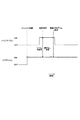
図2は、本実施形態において実行されるサブマイコン30の仕様選択処理をタイミングチャートにより説明している。電子装置10では、装置が備えるACコード11(図1参照)が外部の商用電源と接続し且つ装置に対してユーザから電源オンの指示がなされていない状態(スタンバイ状態)においては、サブマイコン30に対して駆動電圧の供給が開始され、サブマイコン30は駆動状態(オン状態)となる。これにより、スタンバイ状態においてサブマイコン30はリモコンI/F60や操作パネル61に対する入力を監視することができる。一方、スタンバイ状態においては、メインマイコン20には基本的に駆動電圧は供給されず、駆動停止状態(オフ状態)となる。ただし本実施形態では、ACコード11接続後のスタンバイ状態において、一時的にメインマイコン20に駆動電圧が供給されオン状態となる。
FIG. 2 is a timing chart illustrating the specification selection process of the sub-microcomputer 30 executed in the present embodiment. In the
メインマイコン20が一時的にオン状態となった場合、メインマイコン20とサブマイコン30との間でIICバス40を介して所定のコマンドを送受信することで通信が確立し、かかる通信確立後、メインマイコン20はサブマイコン30に対し、ROM22に格納されている仕様情報が示す仕様を選択させるための選択指示をIICバス40を介して送信する。この選択指示をメインマイコン20から受信したサブマイコン30は、ROM32に格納されている制御プログラムの中から、選択指示が示す仕様に対応する制御プログラムを選択し、当該選択した制御プログラムをRAM33上に読み出す。以後、サブマイコン30は、自身がオフ状態となるまで(ACコード11が外部の電源から抜かれるまで)当該選択した制御プログラムに従った処理(リモコンI/F60や操作パネル61による操作入力の解釈および当該解釈結果のメインマイコン20への通知、当該解釈結果に応じたLED62や表示パネル63の制御など。)を実行する。
When the
メインマイコン20は、仕様情報をサブマイコン30に対し送信した後、再びオフ状態へ移行する(電子装置10はスタンバイ状態)。上記のようにサブマイコン30が電子装置10の仕様を認識し、仕様に応じた制御プログラムを選択して以降、ユーザがリモコン装置70等を操作して電源オンの指示を行なったときに、サブマイコン30は当該電源オンの指示を受け付けてメインマイコン20に対し電源オンの指示をIICバス40を介して送信する。するとメインマイコン20がオン状態となり、メインマイコン20が電源回路52を制御することにより電子装置10の他の各構成へ駆動電圧が供給され電子装置10がスタンバイ状態から電源オン状態へ移行することとなる。
After transmitting the specification information to the sub-microcomputer 30, the
このように本実施形態によれば、サブマイコン30は電子装置10の各仕様に対応した制御プログラムを予め保持し、電子装置10のスタンバイ状態中にメインマイコン20が一時的に起動した直後にメインマイコン20から仕様の選択指示を受信し、受信した選択指示に基づいて制御プログラムを選択するようにした。この結果、従来のように電子装置の仕様毎にサブマイコンのハードウェア構成の変更を行なってサブマイコンの機能を電子装置の仕様に対応させていた場合と比較して、サブマイコンによる仕様選択が容易となり、仕様が異なる電子装置10を製造する現場における作業負担が大幅に軽減される。上述したようにメインマイコン20のROM22に記憶される仕様情報は書き換え可能であるため、仕様が異なる電子装置10を製造する場合には、仕様毎にメインマイコン20のROM22に異なる仕様情報を書き込めばよい。
As described above, according to the present embodiment, the sub-microcomputer 30 holds the control program corresponding to each specification of the
本発明は上述した実施形態に限られず、種々の他の態様にて実施可能である。次に、本発明の変形例について説明する。
上述した実施形態においては、サブマイコン30は、メインマイコン20から上記選択指示を受信するまでは、電子装置10の仕様が判らないため外部からの操作に基づく指示を解釈することができない。そこで、サブマイコン30は、メインマイコン20からの上記選択指示に応じて制御プログラムを選択する前に、電子装置10の仕様に関わらず指示内容が予め決められている所定の指示信号を外部からの操作(リモコン装置70や操作パネル61の操作)によって受け付けた場合は、当該指示信号に応じた処理を実行する構成としてもよい。
The present invention is not limited to the above-described embodiment, and can be implemented in various other modes. Next, a modified example of the present invention will be described.
In the embodiment described above, the sub-microcomputer 30 cannot interpret the instruction based on the operation from the outside because the specification of the
一例として、サブマイコン30は、メインマイコン20からの上記選択指示に応じた制御プログラムの選択をする前の状態において、電子装置10の仕様に関わらず指示内容が電源オンの指示に予め決められている所定の指示信号を上記外部からの操作によって受け付けた場合は、即座にメインマイコン20に対して電源オンの指示を送信し、メインマイコン20に電子装置10を電源オン状態にさせるための電源制御処理を実行させる。つまり、電源オンを指示するためのボタン等のリモコン装置70や操作パネル61における位置は電子装置10の仕様によらず一定としておき、サブマイコン30は当該ボタン等が操作されたときに受け付ける指示信号(電気信号)については、電子装置10の仕様に関わらず常に電源オンの指示であると解釈する。かかる構成とすることで、サブマイコン30がメインマイコン20からの上記選択指示に応じて制御プログラムを選択するよりも前のタイミングでユーザがリモコン装置70等を操作して装置の電源オンを指示したときに、当該指示に即座に対応して装置を電源オン状態にすることができる。
As an example, in the state before selecting the control program according to the selection instruction from the
また、上記のように電子装置10のスタンバイ状態における一時期にメインマイコン20が起動してサブマイコン30に送信する情報は、仕様の選択指示に限られない。例えば、メインマイコン20は上記一時的にオン状態となったときに、電子装置10の仕様に応じてリモートロックの設定指示をサブマイコン30に送信してもよい。リモートロックとは、リモコン装置70からの指示に反応しないことを言う。つまりメインマイコン20は、仕様情報が示す仕様が所定の仕様である場合には、仕様の選択指示とともにリモートロックの設定指示をサブマイコン30に送信する。リモートロックの設定指示を受信したサブマイコン30は、以後、リモートロックの解除指示を受け付けるまではリモコン装置70からの指示を受け付けない。ユーザは、リモートロックの解除指示は、操作パネル61を操作することで行なうことができる。
In addition, the information transmitted from the
10…電子装置、11…ACコード、20…メインマイコン、21,31…CPU、22,32…ROM、23,33…RAM、40…IICバス、60…リモコンI/F、61…操作パネル、70…リモコン装置
DESCRIPTION OF
Claims (4)
サブマイコンは、電子装置の異なる各仕様にそれぞれ対応した複数の制御プログラムを格納した第1メモリーを備え、
メインマイコンは、電子装置の仕様を特定する仕様情報を格納した第2メモリーを備え、当該第2メモリーに格納した仕様情報に基づく仕様の選択指示をサブマイコンに送信し、
サブマイコンは、上記第1メモリーに格納した複数の制御プログラムの中から、上記送信された選択指示が示す仕様に対応する制御プログラムを選択し、当該選択した制御プログラムに従った処理を実行する、ことを特徴とする電子装置。 An electronic device having a main microcomputer that controls a predetermined function of the electronic device and a sub-microcomputer that executes at least processing according to an operation from the outside according to a control program,
The sub-microcomputer includes a first memory storing a plurality of control programs corresponding to different specifications of the electronic device,
The main microcomputer includes a second memory storing specification information for specifying the specifications of the electronic device, and transmits a specification selection instruction based on the specification information stored in the second memory to the sub-microcomputer.
The sub-microcomputer selects a control program corresponding to the specification indicated by the transmitted selection instruction from the plurality of control programs stored in the first memory, and executes processing according to the selected control program. An electronic device characterized by that.
サブマイコンは、電子装置の異なる各仕様にそれぞれ対応した複数の制御プログラムを格納した第1メモリーを備え、
メインマイコンは、電子装置の仕様を特定する仕様情報を格納した第2メモリーを備え、
電子装置が備えるACコードが外部電源と接続し且つ電子装置に対して電源オンの指示がなされていないスタンバイ状態においては、サブマイコンは駆動状態でありメインマイコンは駆動停止状態であり、
上記スタンバイ状態においてメインマイコンは、一時的に駆動状態となり、サブマイコンとの間で双方向通信バスによる通信を確立した後に、上記第2メモリーに格納した仕様情報に基づく仕様の選択指示をサブマイコンに送信し、当該送信後に駆動停止状態へ戻り、
サブマイコンは、上記第1メモリーに格納した複数の制御プログラムの中から、上記送信された選択指示が示す仕様に対応する制御プログラムを選択し、当該選択した制御プログラムに従って少なくとも上記外部からの操作の解釈および当該解釈に応じた処理を実行し、
サブマイコンは、メインマイコンからの上記選択指示に応じた制御プログラムの選択を実行していない状態において、電子装置の仕様に関わらず指示内容が電源オンの指示に予め決められている所定の指示信号を上記外部からの操作によって受け付けた場合は、メインマイコンに対して電源オンの指示を送信し、メインマイコンに電子装置を電源オン状態にさせるための電源制御処理を実行させることを特徴とする電子装置。 An electronic device having a main microcomputer that controls predetermined functions including a video processing function and a power supply control function, and a sub-microcomputer that executes at least processing according to an external operation via a remote control device or an operation panel according to a control program There,
The sub-microcomputer includes a first memory storing a plurality of control programs corresponding to different specifications of the electronic device,
The main microcomputer includes a second memory storing specification information for specifying the specifications of the electronic device.
In a standby state in which the AC cord provided in the electronic device is connected to an external power source and the electronic device is not instructed to turn on the power, the sub-microcomputer is in a driving state and the main microcomputer is in a driving stop state.
In the standby state, the main microcomputer is temporarily driven, and after establishing communication with the sub-microcomputer via the bidirectional communication bus, the sub-microcomputer issues a specification selection instruction based on the specification information stored in the second memory. To the drive stop state after the transmission,
The sub-microcomputer selects a control program corresponding to the specification indicated by the transmitted selection instruction from the plurality of control programs stored in the first memory, and performs at least the operation from the outside according to the selected control program. Interpretation and processing according to the interpretation,
In a state where the sub-microcomputer is not executing the selection of the control program according to the selection instruction from the main microcomputer, a predetermined instruction signal whose instruction content is predetermined as a power-on instruction regardless of the specifications of the electronic device Is received by an operation from the outside, an instruction to turn on the power is transmitted to the main microcomputer, and the main microcomputer is caused to execute a power control process for turning on the electronic device. apparatus.
Priority Applications (2)
| Application Number | Priority Date | Filing Date | Title |
|---|---|---|---|
| JP2011012800A JP2012155444A (en) | 2011-01-25 | 2011-01-25 | Electronic equipment |
| US13/354,348 US8549188B2 (en) | 2011-01-25 | 2012-01-20 | Electronic device with main microcomputer and sub microcomputer |
Applications Claiming Priority (1)
| Application Number | Priority Date | Filing Date | Title |
|---|---|---|---|
| JP2011012800A JP2012155444A (en) | 2011-01-25 | 2011-01-25 | Electronic equipment |
Publications (1)
| Publication Number | Publication Date |
|---|---|
| JP2012155444A true JP2012155444A (en) | 2012-08-16 |
Family
ID=46545052
Family Applications (1)
| Application Number | Title | Priority Date | Filing Date |
|---|---|---|---|
| JP2011012800A Pending JP2012155444A (en) | 2011-01-25 | 2011-01-25 | Electronic equipment |
Country Status (2)
| Country | Link |
|---|---|
| US (1) | US8549188B2 (en) |
| JP (1) | JP2012155444A (en) |
Cited By (2)
| Publication number | Priority date | Publication date | Assignee | Title |
|---|---|---|---|---|
| WO2019235286A1 (en) * | 2018-06-08 | 2019-12-12 | 住友電装株式会社 | Communication device and control method |
| JP2019214353A (en) * | 2018-06-08 | 2019-12-19 | 住友電装株式会社 | Communication device and control method |
Families Citing this family (2)
| Publication number | Priority date | Publication date | Assignee | Title |
|---|---|---|---|---|
| KR102019717B1 (en) * | 2013-01-29 | 2019-09-09 | 삼성전자 주식회사 | Apparatus and method for managing memory of mobile terminal |
| KR20160041282A (en) * | 2014-10-07 | 2016-04-18 | 삼성전자주식회사 | Electronic device and controlling method thereof |
Family Cites Families (4)
| Publication number | Priority date | Publication date | Assignee | Title |
|---|---|---|---|---|
| JP2003317382A (en) | 2002-04-15 | 2003-11-07 | Sanyo Electric Co Ltd | Control method for optical disk recording and reproducing device |
| JP4611058B2 (en) | 2005-03-02 | 2011-01-12 | 船井電機株式会社 | Electronic equipment |
| US8407428B2 (en) * | 2010-05-20 | 2013-03-26 | Hicamp Systems, Inc. | Structured memory coprocessor |
| US9053272B2 (en) * | 2011-07-15 | 2015-06-09 | Tictran Corp. | Method and apparatus of hardware acceleration of EDA tools for a programmable logic device |
-
2011
- 2011-01-25 JP JP2011012800A patent/JP2012155444A/en active Pending
-
2012
- 2012-01-20 US US13/354,348 patent/US8549188B2/en not_active Expired - Fee Related
Cited By (5)
| Publication number | Priority date | Publication date | Assignee | Title |
|---|---|---|---|---|
| WO2019235286A1 (en) * | 2018-06-08 | 2019-12-12 | 住友電装株式会社 | Communication device and control method |
| JP2019214353A (en) * | 2018-06-08 | 2019-12-19 | 住友電装株式会社 | Communication device and control method |
| CN113169907A (en) * | 2018-06-08 | 2021-07-23 | 住友电装株式会社 | Communication apparatus and control method |
| CN113169907B (en) * | 2018-06-08 | 2022-06-07 | 住友电装株式会社 | Communication apparatus and control method |
| JP7147525B2 (en) | 2018-06-08 | 2022-10-05 | 住友電装株式会社 | Communication device and control method |
Also Published As
| Publication number | Publication date |
|---|---|
| US8549188B2 (en) | 2013-10-01 |
| US20120191992A1 (en) | 2012-07-26 |
Similar Documents
| Publication | Publication Date | Title |
|---|---|---|
| US11405677B2 (en) | System and method for configuring controlling device functionality | |
| KR102157620B1 (en) | Display device and calibration method thereof | |
| JP4187037B2 (en) | Remote control system | |
| US7827319B2 (en) | Interactive control apparatus using remote control signal between computer and electric home appliance | |
| EP2608563B1 (en) | Method and repeater for controlling multimedia interfaces | |
| WO2017109961A1 (en) | Video display device | |
| JP2012155444A (en) | Electronic equipment | |
| CN103810984A (en) | Display apparatus and method for controlling thereof | |
| WO2010103799A1 (en) | Electronic device and optical disk playback device that are able to be connected to an external device | |
| JP6028896B2 (en) | Projector and projector control method | |
| US20110181386A1 (en) | Providing Guidance During Operation of a Universal Remote Control | |
| US8780095B2 (en) | Projector and control method | |
| KR101263151B1 (en) | Inverter system and inverter | |
| EP3671685B1 (en) | Electronic apparatus and controlling method thereof | |
| EP3461137B1 (en) | Display device and control method thereof, and recording media | |
| US20170238050A1 (en) | Method for transmitting and receiving data using hdmi and device therefor | |
| JP2007043254A (en) | Remote controller and control method of remote controller | |
| CN105359198B (en) | System and method for fast configuration of universal control devices | |
| JP2013207308A (en) | Display device and source apparatus | |
| JP2011004067A (en) | Digital av apparatus, tool for copying setting data, and method for copying setting data | |
| JP2011019063A (en) | Display processor for images | |
| JP4603911B2 (en) | AV system controller and AV apparatus including the AV system controller | |
| WO2011019013A1 (en) | Electronic device | |
| JP2011193234A (en) | Remote operation information switching apparatus | |
| US20100177034A1 (en) | Portable storage device having user interface and method of controlling the user interface |