JP2012152006A - Rotary electric machine - Google Patents
Rotary electric machine Download PDFInfo
- Publication number
- JP2012152006A JP2012152006A JP2011008581A JP2011008581A JP2012152006A JP 2012152006 A JP2012152006 A JP 2012152006A JP 2011008581 A JP2011008581 A JP 2011008581A JP 2011008581 A JP2011008581 A JP 2011008581A JP 2012152006 A JP2012152006 A JP 2012152006A
- Authority
- JP
- Japan
- Prior art keywords
- winding
- group
- phase
- slot
- wound
- Prior art date
- Legal status (The legal status is an assumption and is not a legal conclusion. Google has not performed a legal analysis and makes no representation as to the accuracy of the status listed.)
- Withdrawn
Links
Images


Abstract
Description
本発明は、自動車やトラック等に搭載される回転電機に関する。また、産業用機器、家庭電化製品等への適用も可能である。 The present invention relates to a rotating electrical machine mounted on an automobile, a truck, or the like. Further, it can be applied to industrial equipment, home appliances and the like.
従来より、回転電機として、電機子鉄心とこの電機子鉄心に分布巻き方式で巻装される複数相の電機子巻線とからなる電機子を備えるものがある。
そして、電機子巻線を巻装する方法としては、予め成形した導体セグメントを電機子鉄心に装着する方法(特許文献1参照)があるが、この方法では、電機子鉄心に装着する前に、導体セグメントを成形する工程と、電機子鉄心に導体セグメントを組み付ける工程とを経なければならず、製造工程が増加するという問題点がある。
2. Description of the Related Art Conventionally, some rotary electric machines include an armature including an armature core and a plurality of armature windings wound around the armature core in a distributed winding manner.
And as a method of winding the armature winding, there is a method of mounting a pre-formed conductor segment on the armature core (see Patent Document 1), but in this method, before mounting on the armature core, There is a problem in that the manufacturing process increases because a process of forming the conductor segment and a process of assembling the conductor segment to the armature core are required.
そこで、製造工程の低減の観点からは、導体セグメントを予め成形することなく、導線のような連続導体を電機子鉄心に直接連続的に(途中で接続することなく)巻いていく方法が好ましい。
そして、直接連続的に巻く際の巻きやすさの観点から、電機子巻線を幾つかのグループに分けて巻く方法がある。
Therefore, from the viewpoint of reducing the manufacturing process, a method of winding a continuous conductor such as a conductor directly and continuously on an armature core without forming a conductor segment in advance (without connecting in the middle) is preferable.
From the viewpoint of ease of winding when directly and continuously winding, there is a method of winding the armature winding in several groups.
しかしながら、電機子巻線を幾つかのグループに分ける場合には、異なるグループ間でインピーダンスのばらつきが生じる虞がある。これにより、電機子巻線のインピーダンスの不均衡が生じ、電流不均衡を招く虞がある。 However, when the armature windings are divided into several groups, there is a possibility that variations in impedance occur between different groups. As a result, an impedance imbalance of the armature winding occurs, which may cause a current imbalance.
そこで、本発明は、連続導体を電機子鉄心に直接連続的に巻く方法で形成しても、電機子巻線におけるインピーダンスの均一化を図ることのできる分布巻き方式の回転電機を提供することを目的とする。 Therefore, the present invention provides a distributed winding type rotating electrical machine that can achieve uniform impedance in an armature winding even if a continuous conductor is formed by a method of continuously winding it around an armature core. Objective.
〔請求項1の手段〕
請求項1に記載の回転電機は、周方向に並ぶ複数のティースを有する電機子鉄心と、
ティース間のスロット内に分布巻き方式で配されるm相巻線(mは正の整数)より形成された電機子巻線とを備える。
[Means of Claim 1]
The rotating electrical machine according to
And an armature winding formed of m-phase windings (m is a positive integer) disposed in a slot between the teeth in a distributed winding manner.
そして、m相巻線は、第1のm相巻線群と第2のm相巻線群との2つのグループに分けられており、第1のm相巻線群を構成する各相の導線の巻き始めは、1番目〜m番目のスロットにそれぞれ配され、第2のm相巻線群を構成する各相の導線の巻き始めは、(m+1)番目〜2m番目のスロットにそれぞれ配される。そして、m相巻線群毎に、それぞれの巻き始めから、電機子鉄心の周方向へ波状に巻かれている。 The m-phase windings are divided into two groups, a first m-phase winding group and a second m-phase winding group, and each phase constituting the first m-phase winding group is divided into two groups. The winding start of the conducting wire is arranged in the 1st to mth slots, respectively, and the winding start of the conducting wire of each phase constituting the second m-phase winding group is arranged in the (m + 1) th to 2mth slots, respectively. Is done. Each m-phase winding group is wound in a wave shape in the circumferential direction of the armature core from the start of each winding.
そして、電機子鉄心の径方向において、スロットが径方向に開口する側をスロット先端側、その反対をスロット根元側とし、スロット内の巻線位置において、スロット根元側を第1層、スロット先端側を第2層と定義すると、第1のm相巻線群と第2のm相巻線群とは、第1層から出たm相巻線群が第2層へ入り、第2層から出たm相巻線群が第1層に入るように巻かれている。これにより、スロット内で、第1のm相巻線群と第2のm相巻線群とが径方向に交互に配置されている。 And, in the radial direction of the armature core, the side where the slot opens in the radial direction is the slot tip side, and the opposite is the slot root side. At the winding position in the slot, the slot root side is the first layer, the slot tip side Is defined as the second layer, the first m-phase winding group and the second m-phase winding group are the m-phase winding group coming out of the first layer and entering the second layer. The m-phase winding group that comes out is wound so as to enter the first layer. Thereby, the first m-phase winding group and the second m-phase winding group are alternately arranged in the radial direction in the slot.
これによれば、1つのm相巻線を2つの群に分けているため、巻線作業が行いやすい。
そして、スロット内で、第1のm相巻線群と第2のm相巻線群とが径方向に交互に配置されるように巻かれているため、第1のm相巻線群と第2のm相巻線群との間の巻線長さ、第1のm相巻線群と第2のm相巻線群とが受ける漏れ磁束の影響の受け方が均一化される。このため、巻線抵抗及びリアクタンスが均一化し、インピーダンスを均一化することができる。
According to this, since one m-phase winding is divided into two groups, the winding work is easy to perform.
In the slot, the first m-phase winding group and the second m-phase winding group are wound so as to be alternately arranged in the radial direction. The winding length between the second m-phase winding group and the influence of the leakage magnetic flux received by the first m-phase winding group and the second m-phase winding group are made uniform. For this reason, winding resistance and reactance can be made uniform, and impedance can be made uniform.
〔請求項2の手段〕
請求項2に記載の回転電機によれば、各相の導線は、コイルエンド部においてスロット根元側に捻られている。
[Means of claim 2]
According to the rotating electric machine according to the second aspect, the lead wires of each phase are twisted toward the slot base side at the coil end portion.
これによれば、各相の導線がスロット根元側へ引っ張られるため、たるみが除かれる。このため、たるみによるインピーダンスの不均一を低減できる。また、スプリングバックによる巻きほぐれを防止することができる。 According to this, since the conducting wire of each phase is pulled to the slot base side, slack is removed. For this reason, the nonuniformity of impedance due to sagging can be reduced. Further, it is possible to prevent loosening due to the spring back.
〔請求項3の手段〕
請求項3に記載の回転電機によれば、各相の導線は、電機子鉄心の周方向おいて一方向に波状に巻回されて、巻き始め位置に到達したら、その位置から一方向とは逆方向に波状に巻回されることの繰り返しによって、電機子鉄心に巻線されている。
[Means of claim 3]
According to the rotating electric machine according to
ノズル巻線装置によって直接連続的に各相の導線を電機子鉄心に波状に巻いていく場合、各相の導線を渦巻き状に巻いて径方向に重ねる巻き方(つまり、巻き方向が巻き始めから巻き終わりまで一方向となるような巻き方)をすると、ノズル手前の導線にひずみが生じる虞がある。そのひずみによって導線に加工硬化が生じ、巻きにくくなる場合がある。 When winding each phase of the conducting wire directly and continuously around the armature core by the nozzle winding device, the winding method of winding each phase of the conducting wire in a spiral shape and overlapping in the radial direction (that is, from the beginning of winding) If winding is performed in one direction until the end of winding), there is a risk of distortion in the conductive wire before the nozzle. The strain may cause work hardening in the conductive wire and may be difficult to wind.
そこで、本手段では、巻き始め位置で、電機子鉄心の周方向における巻き方向を切り替えながら、径方向に重ねて巻いていくことで、ノズル手前の導線にひずみを生じにくくすることができる。
また、巻き方向を切り替える際に、導線にテンションを加えて、導線のたるみをとることもできる。
Therefore, in this means, at the winding start position, the winding direction in the circumferential direction of the armature core is switched while being overlapped in the radial direction, thereby making it difficult to cause distortion in the conducting wire before the nozzle.
Further, when the winding direction is switched, tension can be applied to the conducting wire to take up the slack of the conducting wire.
〔請求項4の手段〕
請求項4に記載の回転電機によれば、電機子鉄心は、ティースのスロット根元側に、ティース同士を磁気的に接続するバックヨークを有しており、各相の導線の両端は、バックヨーク側に引き出されて結線されている。
これによれば、コイルエンド高さを高くすることなく結線処理ができる。
[Means of claim 4]
According to the rotating electric machine according to
According to this, the wiring process can be performed without increasing the coil end height.
本発明を実施するための形態を以下の実施例により詳細に説明する。 The mode for carrying out the present invention will be described in detail with reference to the following examples.
〔実施例1の構成〕
実施例1の回転電機の構成を、図1〜図6を用いて説明する。
実施例1の回転電機は、3相交流モータであって、ステータコア2(電機子鉄心)と、このステータコア2に分布巻き方式で巻装されるステータコイル3(電機子巻線)とを有するステータ(電機子)を備える。
そして、このステータコイル3に3相交流電流を流すことにより回転磁界を形成し、回転磁界内に配されるロータ(図示せず)を回転させる。なお、ロータは永久磁石型、電磁石型、鉄心型等、様々な態様をとり得る。
[Configuration of Example 1]
The configuration of the rotating electrical machine according to the first embodiment will be described with reference to FIGS.
The rotating electrical machine according to the first embodiment is a three-phase AC motor, and includes a stator core 2 (armature core) and a stator coil 3 (armature winding) wound around the
A rotating magnetic field is formed by passing a three-phase alternating current through the
ステータコア2は、複数枚の鋼板が積層されて円筒状に形成されている。そして、ステータコア2は、先端がロータに対向するとともに周方向に複数個並んだティース5と、ティース5同士を磁気的に接続するバックヨーク6とを有している(図4参照)。そして、隣合うティース5同士とバックヨーク6とで囲われる空間が、スロット7となっている。そして、ステータコア2の中心にはシャフト(図示せず)が固定されている。
The
本実施例の3相交流モータは、ステータコア2の外周を取り囲むようにロータが配置されるアウターロータ型であり、図4に示すように、ティース5はステータコア2の径方向外側に突出しており、スロット7はステータコア2の径方向外側に向けて開口している。
また、本実施例では、例えば、42個のスロット7が周方向に並んで形成されている。
The three-phase AC motor of the present embodiment is an outer rotor type in which a rotor is disposed so as to surround the outer periphery of the
In the present embodiment, for example, 42
ステータコイル3は、1つの3相巻線(U相コイル、V相コイル、W相コイル)からなっている。
The
〔本実施例の特徴〕
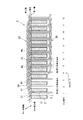
本実施例の3相巻線は、2つの群(第1の3相巻線群11と第2の3相巻線群12)に分かれている(図1、図2参照)。
第1の3相巻線群11(以下、第1群11と呼ぶ)は、U相コイルを形成する導線U1と、V相コイルを形成する導線V1と、W相コイルを形成する導線W1とからなっている。
第2の3相巻線群12(以下、第2群12と呼ぶ)は、U相コイルを形成する導線U2と、V相コイルを形成する導線V2と、W相コイルを形成する導線W2とからなっている。
なお、各導線は、外周に絶縁被覆が施された被覆線であり、線径は例えば1〜2mm程度である。
[Features of this embodiment]
The three-phase winding of this embodiment is divided into two groups (first three-
First three-phase winding group 11 (hereinafter referred to as first group 11) includes a conductive wire U1 that forms a U-phase coil, a conductive wire V1 that forms a V-phase coil, and a conductive wire W1 that forms a W-phase coil. It is made up of.
Second three-phase winding group 12 (hereinafter referred to as second group 12) includes a conductive wire U2 that forms a U-phase coil, a conductive wire V2 that forms a V-phase coil, and a conductive wire W2 that forms a W-phase coil. It is made up of.
In addition, each conducting wire is a covered wire with an insulating coating on the outer periphery, and the wire diameter is, for example, about 1 to 2 mm.
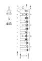
そして、第1群11を構成する各相の導線の巻き始めは、1番目〜3番目(m番目(m=3))のスロットにそれぞれ配される。
すなわち、第1群11の導線U1の巻き始めは1番目のスロット7に配され、導線V1の巻き始めは2番目のスロット7に配され、導線W1の巻き始めは3番目のスロット7に配される。
And the winding start of the conducting wire of each phase which comprises the
That is, the winding start of the conducting wire U1 of the
また、第2群12を構成する各相の導線の巻き始めは、4番目(m+1番目(m=3))〜6番目(2m番目(m=3))のスロット7にそれぞれ配される。
すなわち、第2群12の導線U2の巻き始めは4番目のスロット7に配され、導線V2は5番目のスロット7に配され、導線W2は6番目のスロット7に配される。
In addition, the winding start of the conducting wires of the respective phases constituting the
That is, the winding start of the conducting wire U2 of the
つまり、第1群11の各相の導線と、第2群の各相の導線とは、ともに、U相、V相、W相の順に周方向に並んでおり、第1群11と第2群12との同じ相同士の導線の巻き始めは、3スロット(mスロット(m=3))ずれている。
例えば、第2群12の導線U2の巻き始めは、第1群11の導線U1の巻き始めが配される1番目のスロット7から3スロット進んだ4番目のスロット7に配されている。
That is, the lead wires of each phase of the
For example, the winding start of the conducting wire U2 of the
ここで、電機子鉄心の径方向において、スロット7が径方向に開口する側をスロット先端側、その反対をスロット根元側とし、スロット内の巻線位置において、スロット根元側を第1層、スロット先端側を第2層と定義する。
なお、本実施例では、スロット7がステータコア2の径方向外側に開口しているため、スロット先端側とは径方向外側であり、スロット根元側とは径方向内側(バックヨーク側)となる。
Here, in the radial direction of the armature core, the side where the
In the present embodiment, since the
第1群11(導線U1、V1、W1)の巻き始めは、1〜3番目のスロット7の第1層に配される。
また、第2群12(導線U2、V2、W2)の巻き始めは、4〜6番目のスロット7の第1層に配される。
The winding start of the first group 11 (conductors U1, V1, W1) is arranged in the first layer of the first to
In addition, the winding start of the second group 12 (conductive wires U2, V2, W2) is arranged in the first layer of the fourth to
そして、第1群11と第2群12は、群毎に、それぞれの巻き始めからステータコア2の周方向へ波状に巻かれている(図1、2参照)。すなわち、各導線は、ステータコア2の軸方向端面から突出するコイルエンド部20と、スロット7内に収容されるスロット収容部21とを周方向に交互に有している。
なお、各群は、3本の導線を1セットとして、ノズル巻線装置等によってステータコア2に直接連続的に巻きつけられる。
各導線は、それぞれ3スロット(mスロット(m=3))ピッチで巻かれるため、各スロット7には、それぞれ同相の導線が配されることになる(図1〜3参照)。
And the
Each group is wound around the
Since each conducting wire is wound at a pitch of 3 slots (m slot (m = 3)), a conducting wire of the same phase is arranged in each slot 7 (see FIGS. 1 to 3).
そして、第1群11と第2群12は、それぞれ波状に巻かれる際に、第1層から出た群が第2層へ入り、第2層から出た群が第1層に入るように巻かれる。
つまり、第1群11の各導線U1、V1、W1は、1〜3番目のスロット7から軸方向他端側へ引き出されて、それぞれ3スロット進んだ次のスロット7へ挿入される。この際、次のスロット(4〜6番目のスロット7)では第2層に配される。なお、上述のように、4〜6番目のスロット7の第1層には、第2群12の導線U2、V2、W2がそれぞれ配されている。
Then, when the
That is, each conducting wire U1, V1, W1 of the
そして、7番目以降のスロット7にも同じ要領で巻かれる。すなわち、7〜9番目のスロット7では第1群11の各導線が第1層に配され、10〜12番目のスロット7では第1群11の各導線が第2層に配される。
And it winds also in the 7th and
そして、第2群12も第1群11と同じ要領で巻かれている。すなわち、第2群12の導線U2、V2、W2は、4〜6番目のスロット7から軸方向他端側へ引き出されて、それぞれ3スロット進んだ次のスロット7へ挿入される。この際、次のスロット(7〜9番目のスロット7)では第2層に配される。そして、10番目以降のスロット7にも同じ要領で巻かれる。
The
第2群12は、第1群11よりも巻き始めが3スロット進んでいるため、第1群11と同じ要領で巻くと、図1、3に示すように、3スロット毎に、第1層に配される群と、第2層に配される群とが逆になる。
In the
なお、図1、3では、ステータコア2の周方向への波状巻回の1周目のみを図示しているが、2周目以降も同様に巻かれる。
これにより、スロット7内で、第1群11と第2群12とが径方向に交互に配置される。
1 and 3, only the first round of the undulating winding in the circumferential direction of the
Thus, the
〔各導線のコイルエンド部での取り回し態様について〕
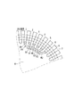
次に、図4を用いて、各導線(U1、V1、W1、U2、V2、W2)のコイルエンド部20での取り回し態様を説明する。なお、図4は、2周目以降の各導線の図示が省略されている。
[About the handling mode at the coil end of each conductor]
Next, using FIG. 4, the manner in which the lead wires (
なお、コイルエンド部20とは、各導線が次のスロット7へ入る際に、異なる相が入るスロット7を跨ぐことにより形成され、ステータコア2の軸方向端面から突出する導線の部分を指す。
The
そして、各導線は、コイルエンド部20においてスロット根元側(径方向内側)に捻られている。
すなわち、各導線は、ステータコア2の軸方向端面を渡る際に、スロット根元側(径方向内側)に押し付けるように巻かれ、コイルエンド部20は内側に凸となる弧を描くように巻かれる。
なお、各導線は、スロット7から引き出された後、径方向内側に押しつけて倒しこみながら、ステータコア2の軸方向端面を渡らせて、コイルエンド部20を形成している。
And each conducting wire is twisted in the
That is, each conductor wire is wound so as to be pressed against the slot base side (radially inner side) when crossing the axial end surface of the
In addition, after each lead wire is pulled out from the
〔各導線の周方向への巻き方向について〕
次に、図5を用いて、各導線のステータコア2の周方向における巻き方向について説明する。
本実施例では、各導線が、ステータコア2の周方向おいて一方向に波状に巻回されて、周方向において巻き始め位置に到達したら、その位置から一方向とは逆方向に波状に巻回されることの繰り返しによって、ステータコア2に巻線されている。
[About the winding direction of each conductor in the circumferential direction]
Next, the winding direction in the circumferential direction of the
In this embodiment, each conductive wire is wound in one direction in the circumferential direction of the
すなわち、第1群11は、1〜3番目のスロット7から、第2群12は、4〜6番目のスロット7から、それぞれ、周方向の一方向に波状に巻かれ(1周目)、1〜3番目のスロット7、4〜6番目のスロット7に戻り、1周目の外側に2周目を巻き始める際には、巻き方向を反転させて、2周目は一方向とは逆方向に巻かれる。同様に、3周目も、巻き始め位置で巻き方向が反転し、一方向に巻かれる。これが、所定周を達成する巻き終わりまで繰り返される。
That is, the
〔各導線の巻き始め端及び巻き終わり端の結線処理について〕
各導線の巻き始め端及び巻き終わり端の結線処理について、図6を用いて説明する。
各相の導線の両端(巻き始め端25と巻き終わり端(図示せず))は、バックヨーク側に引き出されて結線されている。
[About the wire connection at the winding start end and winding end of each conductor]
The connection process of the winding start end and winding end end of each conducting wire will be described with reference to FIG.
Both ends (winding
すなわち、本実施例では、各導線に巻き始め端25は、巻き始め位置のスロット7の軸方向一端側に引き出されており、ステータコア2の軸方向一端面上でバックヨーク側(径方向内側)に取り回されている。
That is, in this embodiment, the winding start end 25 of each conductive wire is drawn out to one end side in the axial direction of the
また、本実施例では、バックヨーク6に軸方向貫通する貫通穴30が形成されており、軸方向一端側でバックヨーク側に引き出された巻き始め端25が、貫通穴30を通って、ステータコア2の軸方向他端側に引き出されている。
そして、ステータコア2の軸方向他端側では、巻き終わり端がコイルエンド部20を横断してバックヨーク側に取り回されており、ステータコア2の軸方向他端面上で、各導線の巻き始め端25と巻き終わり端が任意の接続態様に結線される。
Further, in the present embodiment, the through-
On the other end side in the axial direction of the
本実施例では、導線U1とU2とが直列接続されるように結線され、導線V1とV2とが直列に接続されるように結線され、導線W1とW2とが直列に接続されるように結線される。そして、直列接続された各相の導線がスター結線される。 In this embodiment, the conductive wires U1 and U2 are connected so as to be connected in series, the conductive wires V1 and V2 are connected so as to be connected in series, and the conductive wires W1 and W2 are connected so as to be connected in series. Is done. And the conducting wire of each phase connected in series is star-connected.
〔実施例1の作用効果〕
本実施例のステータコイル3を形成する3相巻線は、2つの群に分けられており、第1群11と第2群12は、群毎に、それぞれの巻き始めからステータコア2の周方向へ波状に巻かれている。
導線をステータコア2に直接連続的に巻きつけていく場合には、1つの3相巻線を群に分けずに巻くよりも、2つの群に分けた方が巻線作業が行いやすい。
[Effects of Example 1]
The three-phase windings forming the
When the conductive wire is directly and continuously wound around the
また、本実施例では、第1群11と第2群12は、それぞれ波状に巻かれる際に、第1層から出た群が第2層へ入り、第2層から出た群が第1層に入るように巻かれ、スロット7内で、第1群11と第2群12とが径方向に交互に配置される。
Further, in the present embodiment, when the
これによれば、第1群11と第2群12の巻線長さ、第1群11と第2群12とが受ける漏れ磁束の影響の受け方が均一化される。このため、巻線抵抗及びリアクタンスが均一化し、インピーダンスを均一化することができる。
According to this, the winding lengths of the
また、本実施例では、各導線(U1、V1、W1、U2、V2、W2)が、コイルエンド部20においてスロット根元側に捻られている。
これによれば、スロット根元側への捻じることで、各導線が引っ張られ、たるみを除くことができる。このため、たるみによるインピーダンスの不均一を低減できる。また、スプリングバックによる巻きほぐれを防止することができる。
Further, in this embodiment, each of the conducting wires (U1, V1, W1, U2, V2, W2) is twisted toward the slot base side in the
According to this, by twisting to the slot base side, each conducting wire is pulled and slack can be removed. For this reason, the nonuniformity of impedance due to sagging can be reduced. Further, it is possible to prevent loosening due to the spring back.
また、本実施例の回転電機によれば、各導線は、ステータコア2の周方向おいて一方向に波状に巻回されて、周方向において巻き始め位置に到達したら、その位置から一方向とは逆方向に波状に巻回されることの繰り返しによって、ステータコア2に巻線されている。
Further, according to the rotating electric machine of the present embodiment, each conductor is wound in one direction in the circumferential direction of the
ノズル巻線装置によって直接連続的に導線をステータコア2に波状に巻いていく場合、導線を渦巻き状に巻いて径方向に重ねる巻き方(つまり、巻き方向が巻き始めから巻き終わりまで一方向となるような巻き方)をすると、ノズル手前の導線にひずみが生じる虞がある。そのひずみによって導線に加工硬化が生じ、巻きにくくなる場合がある。
When the conductor is wound directly and continuously around the
そこで、本実施例では、巻き始め位置で、ステータコア2の周方向における巻き方向を切り替えながら、径方向に重ねて巻いていくことで、ノズル手前の各導線にひずみを生じにくくすることができる。
また、巻き方向を切り替える際に、各導線にテンションを加えて、各導線のたるみをとることもできる。これにより、各導線の長さを調節し、異なる群間、異なる相間でのインピーダンスの均一化を図ることができる。
Therefore, in this embodiment, at the winding start position, by switching the winding direction in the circumferential direction of the
Further, when the winding direction is switched, tension can be applied to each conductor to take up the slack of each conductor. Thereby, the length of each conducting wire can be adjusted, and the impedance can be equalized between different groups and between different phases.
また、本実施例によれば、各導線の両端(巻き始め端25と巻き終わり端(図示せず))は、バックヨーク側に引き出されて結線されている。
例えば、コイルエンド部20上で結線する場合は、コイルエンド高さが高くなってしまうが、本実施例では、各導線の両端をバックヨーク側に引き出してコイルエンド部20と干渉しない位置で結線処理がなされるため、結線処理によってコイルエンド高さが高くなることはない。
Further, according to the present embodiment, both ends (winding
For example, when connecting on the
〔変形例〕
本発明の実施態様は、実施例に限定されず種々の変形例を考えることができる。
例えば、回転電機は3相交流モータであったが、複数相のコイルを有する回転電機であればよく、3相交流モータに限られない。
また、ロータが電機子となる回転電機にも本発明を適用することができる。
[Modification]
Embodiments of the present invention are not limited to the examples, and various modifications can be considered.
For example, the rotary electric machine is a three-phase AC motor, but may be any rotary electric machine having a plurality of phase coils, and is not limited to a three-phase AC motor.
The present invention can also be applied to a rotating electrical machine in which the rotor is an armature.
また、実施例1では、アウターロータタイプの3相交流モータであったが、インナーロータタイプでもよい。インナーロータタイプの場合には、スロット根元側が径方向外側、スロット先端側が径方向内側になる。 In the first embodiment, the outer rotor type three-phase AC motor is used. However, an inner rotor type may be used. In the case of the inner rotor type, the slot base side is the radially outer side, and the slot tip side is the radially inner side.
また、実施例1では、各相の導線(U1とU2、V1とV2、W1とW2)が直列に結線されていたが、並列に接続されていてもよい。
また、実施例1では、軸方向一端側でバックヨーク側に引き出された巻き始め端25が、貫通穴30を通って、ステータコア2の軸方向他端側に引き出されていたが、貫通穴30を設けなくてもよい。すなわち、巻き終わり端を軸方向一端側のバックヨーク側へ取り回し、ステータコアの軸方向一端側のバックヨーク6上で結線してもよい。
Moreover, in Example 1, although the conducting wire (U1 and U2, V1 and V2, W1 and W2) of each phase was connected in series, you may connect in parallel.
Further, in Example 1, the winding start end 25 drawn to the back yoke side on one axial end side is drawn to the other axial end side of the
2 ステータコア(電機子鉄心)
3 ステータコイル(電機子巻線)
5 ティース
6 バックヨーク
7 スロット
11 第1群(第1の3相巻線群)
12 第2群(第2の3相巻線群)
20 コイルエンド部
25 巻き始め端
U1、V1、W1、U2、V2、W2 導線
2 Stator core (armature core)
3 Stator coil (armature winding)
5
12 Second group (second three-phase winding group)
20
Claims (4)
前記ティース間のスロット内に分布巻き方式で配されるm相巻線(mは正の整数)より形成された電機子巻線とを備える回転電機において、
前記m相巻線は、第1のm相巻線群と第2のm相巻線群との2つのグループに分けられており、
前記第1のm相巻線群を構成する各相の導線の巻き始めは、1番目〜m番目のスロットにそれぞれ配され、
前記第2のm相巻線群を構成する各相の導線の巻き始めは、(m+1)番目〜2m番目のスロットにそれぞれ配され、
前記m相巻線群毎に、それぞれの巻き始めから、前記電機子鉄心の周方向に波状に巻かれており、
前記電機子鉄心の径方向において、前記スロットが径方向に開口する側をスロット先端側、その反対をスロット根元側とし、前記スロット内の巻線位置において、スロット根元側を第1層、スロット先端側を第2層と定義すると、
前記第1のm相巻線群と前記第2のm相巻線群とは、第1層から出たm相巻線群が第2層へ入り、第2層から出たm相巻線群が第1層に入るように巻かれ、
前記スロット内で、前記第1のm相巻線群と前記第2のm相巻線群とが径方向に交互に配置されていることを特徴とする回転電機。 An armature core having a plurality of teeth arranged in the circumferential direction;
In a rotating electrical machine comprising an armature winding formed of an m-phase winding (m is a positive integer) arranged in a distributed winding manner in a slot between the teeth,
The m-phase windings are divided into two groups, a first m-phase winding group and a second m-phase winding group,
The winding start of the conductive wire of each phase constituting the first m-phase winding group is arranged in the first to m-th slots, respectively.
The winding start of the conductive wire of each phase constituting the second m-phase winding group is arranged in the (m + 1) th to 2mth slots, respectively.
For each m-phase winding group, from the beginning of each winding, it is wound in the circumferential direction of the armature core,
In the radial direction of the armature core, the side where the slot opens in the radial direction is the slot tip side, and the opposite is the slot root side. At the winding position in the slot, the slot root side is the first layer, the slot tip If the side is defined as the second layer,
The first m-phase winding group and the second m-phase winding group are the m-phase windings coming out from the second layer when the m-phase winding group coming out from the first layer enters the second layer. The group is wound to enter the first layer,
In the slot, the first m-phase winding group and the second m-phase winding group are alternately arranged in the radial direction.
前記各相の導線は、記電機子鉄心の軸方向端面から突出するコイルエンド部においてスロット根元側に捻られていることを特徴とする回転電機。 In the rotating electrical machine according to claim 1,
The electric wire of each phase is twisted to the slot base side at the coil end portion protruding from the axial end surface of the armature iron core.
前記各相の導線は、前記電機子鉄心の周方向おいて一方向に波状に巻回されて、巻き始め位置に到達したら、その位置から前記一方向とは逆方向に波状に巻回されることの繰り返しによって、前記電機子鉄心に巻線されていることを特徴とする回転電機。 In the rotating electrical machine according to claim 2 or 2,
The lead wires of each phase are wound in one direction in the circumferential direction of the armature core, and when reaching the winding start position, the lead wires are wound in the opposite direction to the one direction from that position. The rotating electric machine is wound around the armature core by repeating the above.
前記電機子鉄心は、前記ティースのスロット根元側に、前記ティース同士を磁気的に接続するバックヨークを有しており、
前記各相の導線の両端は、前記バックヨーク側に引き出されて結線されていることを特徴とする回転電機。 In the rotating electrical machine according to any one of claims 1 to 3,
The armature core has a back yoke that magnetically connects the teeth to each other on the slot base side of the teeth.
The rotating electrical machine according to claim 1, wherein both ends of the conducting wires of each phase are drawn and connected to the back yoke side.
Priority Applications (1)
| Application Number | Priority Date | Filing Date | Title |
|---|---|---|---|
| JP2011008581A JP2012152006A (en) | 2011-01-19 | 2011-01-19 | Rotary electric machine |
Applications Claiming Priority (1)
| Application Number | Priority Date | Filing Date | Title |
|---|---|---|---|
| JP2011008581A JP2012152006A (en) | 2011-01-19 | 2011-01-19 | Rotary electric machine |
Publications (1)
| Publication Number | Publication Date |
|---|---|
| JP2012152006A true JP2012152006A (en) | 2012-08-09 |
Family
ID=46793733
Family Applications (1)
| Application Number | Title | Priority Date | Filing Date |
|---|---|---|---|
| JP2011008581A Withdrawn JP2012152006A (en) | 2011-01-19 | 2011-01-19 | Rotary electric machine |
Country Status (1)
| Country | Link |
|---|---|
| JP (1) | JP2012152006A (en) |
Citations (7)
| Publication number | Priority date | Publication date | Assignee | Title |
|---|---|---|---|---|
| JPS5060701A (en) * | 1973-09-27 | 1975-05-24 | ||
| JP2009524392A (en) * | 2006-01-16 | 2009-06-25 | ヴァレオ エキプマン エレクトリク モトゥール | Manufacturing method of stator for rotary electric machine and configuration of conductor on support |
| JP2009268219A (en) * | 2008-04-24 | 2009-11-12 | Denso Corp | Stator for rotary electric machine and method of manufacturing the same |
| JP2010130842A (en) * | 2008-11-28 | 2010-06-10 | Sanko Kiki Co Ltd | Stator core and stator core with coil |
| JP2010178458A (en) * | 2009-01-28 | 2010-08-12 | Toyota Motor Corp | Stator |
| JP3162504U (en) * | 2010-06-24 | 2010-09-02 | 国産電機株式会社 | Magnet type AC generator |
| JP2010273482A (en) * | 2009-05-22 | 2010-12-02 | Denso Trim Kk | Three-phase magnet generator |
-
2011
- 2011-01-19 JP JP2011008581A patent/JP2012152006A/en not_active Withdrawn
Patent Citations (7)
| Publication number | Priority date | Publication date | Assignee | Title |
|---|---|---|---|---|
| JPS5060701A (en) * | 1973-09-27 | 1975-05-24 | ||
| JP2009524392A (en) * | 2006-01-16 | 2009-06-25 | ヴァレオ エキプマン エレクトリク モトゥール | Manufacturing method of stator for rotary electric machine and configuration of conductor on support |
| JP2009268219A (en) * | 2008-04-24 | 2009-11-12 | Denso Corp | Stator for rotary electric machine and method of manufacturing the same |
| JP2010130842A (en) * | 2008-11-28 | 2010-06-10 | Sanko Kiki Co Ltd | Stator core and stator core with coil |
| JP2010178458A (en) * | 2009-01-28 | 2010-08-12 | Toyota Motor Corp | Stator |
| JP2010273482A (en) * | 2009-05-22 | 2010-12-02 | Denso Trim Kk | Three-phase magnet generator |
| JP3162504U (en) * | 2010-06-24 | 2010-09-02 | 国産電機株式会社 | Magnet type AC generator |
Similar Documents
| Publication | Publication Date | Title |
|---|---|---|
| JP5692247B2 (en) | Collective conductor for motor winding | |
| US9748810B2 (en) | Motor and method for manufacturing stator therefor | |
| JP5585823B2 (en) | Stator for rotating electric machine and method for manufacturing the same | |
| JP2012152028A (en) | Rotary electric machine | |
| JP5625936B2 (en) | Rotating electric machine | |
| US11418070B2 (en) | Stator and rotary electric machine | |
| TW201521330A (en) | Concentrated type motor | |
| WO2017149934A1 (en) | Winding structure for rotary electric machine stator | |
| US20140285056A1 (en) | Wound member for manufacturing coil, coil, rotating electrical machine, and method for manufacturing coil | |
| CN111555506A (en) | Motor stator and motor | |
| JP4567133B2 (en) | Rotating electric machine and manufacturing method thereof | |
| CN106469949A (en) | Motor and the manufacture method of motor | |
| CN112436617A (en) | Motor stator and motor | |
| CN112531932A (en) | Motor stator and motor | |
| CN214124957U (en) | Motor stator and motor | |
| CN213585304U (en) | Motor stator and motor | |
| CN112583168A (en) | Motor stator winding, stator and motor | |
| CN112332564A (en) | Motor stator and motor | |
| CN112436618A (en) | Motor stator and motor | |
| CN112332566A (en) | Motor stator and motor | |
| CN112332565A (en) | Motor stator and motor | |
| JP2012152006A (en) | Rotary electric machine | |
| CN112821598A (en) | Motor stator and motor | |
| JP5904099B2 (en) | Rotating electric machine stator | |
| CN215344117U (en) | Motor stator and motor |
Legal Events
| Date | Code | Title | Description |
|---|---|---|---|
| A621 | Written request for application examination |
Free format text: JAPANESE INTERMEDIATE CODE: A621 Effective date: 20130221 |
|
| A977 | Report on retrieval |
Free format text: JAPANESE INTERMEDIATE CODE: A971007 Effective date: 20140212 |
|
| A131 | Notification of reasons for refusal |
Free format text: JAPANESE INTERMEDIATE CODE: A131 Effective date: 20140225 |
|
| A521 | Written amendment |
Free format text: JAPANESE INTERMEDIATE CODE: A523 Effective date: 20140417 |
|
| A761 | Written withdrawal of application |
Free format text: JAPANESE INTERMEDIATE CODE: A761 Effective date: 20140619 |