JP2012149643A - Modular tower and method of assembling the same - Google Patents
Modular tower and method of assembling the same Download PDFInfo
- Publication number
- JP2012149643A JP2012149643A JP2012005763A JP2012005763A JP2012149643A JP 2012149643 A JP2012149643 A JP 2012149643A JP 2012005763 A JP2012005763 A JP 2012005763A JP 2012005763 A JP2012005763 A JP 2012005763A JP 2012149643 A JP2012149643 A JP 2012149643A
- Authority
- JP
- Japan
- Prior art keywords
- tower
- section
- assembly
- flange
- panels
- Prior art date
- Legal status (The legal status is an assumption and is not a legal conclusion. Google has not performed a legal analysis and makes no representation as to the accuracy of the status listed.)
- Pending
Links
Images

Classifications
-
- E—FIXED CONSTRUCTIONS
- E04—BUILDING
- E04H—BUILDINGS OR LIKE STRUCTURES FOR PARTICULAR PURPOSES; SWIMMING OR SPLASH BATHS OR POOLS; MASTS; FENCING; TENTS OR CANOPIES, IN GENERAL
- E04H12/00—Towers; Masts or poles; Chimney stacks; Water-towers; Methods of erecting such structures
- E04H12/02—Structures made of specified materials
- E04H12/08—Structures made of specified materials of metal
- E04H12/085—Details of flanges for tubular masts
-
- E—FIXED CONSTRUCTIONS
- E04—BUILDING
- E04H—BUILDINGS OR LIKE STRUCTURES FOR PARTICULAR PURPOSES; SWIMMING OR SPLASH BATHS OR POOLS; MASTS; FENCING; TENTS OR CANOPIES, IN GENERAL
- E04H12/00—Towers; Masts or poles; Chimney stacks; Water-towers; Methods of erecting such structures
- E04H12/02—Structures made of specified materials
- E04H12/08—Structures made of specified materials of metal
-
- E—FIXED CONSTRUCTIONS
- E04—BUILDING
- E04H—BUILDINGS OR LIKE STRUCTURES FOR PARTICULAR PURPOSES; SWIMMING OR SPLASH BATHS OR POOLS; MASTS; FENCING; TENTS OR CANOPIES, IN GENERAL
- E04H12/00—Towers; Masts or poles; Chimney stacks; Water-towers; Methods of erecting such structures
-
- F—MECHANICAL ENGINEERING; LIGHTING; HEATING; WEAPONS; BLASTING
- F03—MACHINES OR ENGINES FOR LIQUIDS; WIND, SPRING, OR WEIGHT MOTORS; PRODUCING MECHANICAL POWER OR A REACTIVE PROPULSIVE THRUST, NOT OTHERWISE PROVIDED FOR
- F03D—WIND MOTORS
- F03D13/00—Assembly, mounting or commissioning of wind motors; Arrangements specially adapted for transporting wind motor components
- F03D13/20—Arrangements for mounting or supporting wind motors; Masts or towers for wind motors
-
- F—MECHANICAL ENGINEERING; LIGHTING; HEATING; WEAPONS; BLASTING
- F03—MACHINES OR ENGINES FOR LIQUIDS; WIND, SPRING, OR WEIGHT MOTORS; PRODUCING MECHANICAL POWER OR A REACTIVE PROPULSIVE THRUST, NOT OTHERWISE PROVIDED FOR
- F03D—WIND MOTORS
- F03D80/00—Details, components or accessories not provided for in groups F03D1/00 - F03D17/00
- F03D80/70—Bearing or lubricating arrangements
-
- F—MECHANICAL ENGINEERING; LIGHTING; HEATING; WEAPONS; BLASTING
- F03—MACHINES OR ENGINES FOR LIQUIDS; WIND, SPRING, OR WEIGHT MOTORS; PRODUCING MECHANICAL POWER OR A REACTIVE PROPULSIVE THRUST, NOT OTHERWISE PROVIDED FOR
- F03D—WIND MOTORS
- F03D80/00—Details, components or accessories not provided for in groups F03D1/00 - F03D17/00
- F03D80/80—Arrangement of components within nacelles or towers
- F03D80/82—Arrangement of components within nacelles or towers of electrical components
-
- F—MECHANICAL ENGINEERING; LIGHTING; HEATING; WEAPONS; BLASTING
- F03—MACHINES OR ENGINES FOR LIQUIDS; WIND, SPRING, OR WEIGHT MOTORS; PRODUCING MECHANICAL POWER OR A REACTIVE PROPULSIVE THRUST, NOT OTHERWISE PROVIDED FOR
- F03D—WIND MOTORS
- F03D9/00—Adaptations of wind motors for special use; Combinations of wind motors with apparatus driven thereby; Wind motors specially adapted for installation in particular locations
- F03D9/20—Wind motors characterised by the driven apparatus
- F03D9/25—Wind motors characterised by the driven apparatus the apparatus being an electrical generator
-
- F—MECHANICAL ENGINEERING; LIGHTING; HEATING; WEAPONS; BLASTING
- F05—INDEXING SCHEMES RELATING TO ENGINES OR PUMPS IN VARIOUS SUBCLASSES OF CLASSES F01-F04
- F05B—INDEXING SCHEME RELATING TO WIND, SPRING, WEIGHT, INERTIA OR LIKE MOTORS, TO MACHINES OR ENGINES FOR LIQUIDS COVERED BY SUBCLASSES F03B, F03D AND F03G
- F05B2240/00—Components
- F05B2240/90—Mounting on supporting structures or systems
- F05B2240/91—Mounting on supporting structures or systems on a stationary structure
- F05B2240/912—Mounting on supporting structures or systems on a stationary structure on a tower
-
- F—MECHANICAL ENGINEERING; LIGHTING; HEATING; WEAPONS; BLASTING
- F05—INDEXING SCHEMES RELATING TO ENGINES OR PUMPS IN VARIOUS SUBCLASSES OF CLASSES F01-F04
- F05B—INDEXING SCHEME RELATING TO WIND, SPRING, WEIGHT, INERTIA OR LIKE MOTORS, TO MACHINES OR ENGINES FOR LIQUIDS COVERED BY SUBCLASSES F03B, F03D AND F03G
- F05B2260/00—Function
- F05B2260/30—Retaining components in desired mutual position
-
- Y—GENERAL TAGGING OF NEW TECHNOLOGICAL DEVELOPMENTS; GENERAL TAGGING OF CROSS-SECTIONAL TECHNOLOGIES SPANNING OVER SEVERAL SECTIONS OF THE IPC; TECHNICAL SUBJECTS COVERED BY FORMER USPC CROSS-REFERENCE ART COLLECTIONS [XRACs] AND DIGESTS
- Y02—TECHNOLOGIES OR APPLICATIONS FOR MITIGATION OR ADAPTATION AGAINST CLIMATE CHANGE
- Y02E—REDUCTION OF GREENHOUSE GAS [GHG] EMISSIONS, RELATED TO ENERGY GENERATION, TRANSMISSION OR DISTRIBUTION
- Y02E10/00—Energy generation through renewable energy sources
- Y02E10/70—Wind energy
- Y02E10/72—Wind turbines with rotation axis in wind direction
-
- Y—GENERAL TAGGING OF NEW TECHNOLOGICAL DEVELOPMENTS; GENERAL TAGGING OF CROSS-SECTIONAL TECHNOLOGIES SPANNING OVER SEVERAL SECTIONS OF THE IPC; TECHNICAL SUBJECTS COVERED BY FORMER USPC CROSS-REFERENCE ART COLLECTIONS [XRACs] AND DIGESTS
- Y02—TECHNOLOGIES OR APPLICATIONS FOR MITIGATION OR ADAPTATION AGAINST CLIMATE CHANGE
- Y02E—REDUCTION OF GREENHOUSE GAS [GHG] EMISSIONS, RELATED TO ENERGY GENERATION, TRANSMISSION OR DISTRIBUTION
- Y02E10/00—Energy generation through renewable energy sources
- Y02E10/70—Wind energy
- Y02E10/728—Onshore wind turbines
Landscapes
- Engineering & Computer Science (AREA)
- Life Sciences & Earth Sciences (AREA)
- Chemical & Material Sciences (AREA)
- General Engineering & Computer Science (AREA)
- Architecture (AREA)
- Sustainable Development (AREA)
- Sustainable Energy (AREA)
- Combustion & Propulsion (AREA)
- Mechanical Engineering (AREA)
- Civil Engineering (AREA)
- Structural Engineering (AREA)
- Wood Science & Technology (AREA)
- Materials Engineering (AREA)
- Power Engineering (AREA)
- Wind Motors (AREA)
- Installation Of Indoor Wiring (AREA)
Abstract
【課題】モジュラータワーのタワーアセンブリを提供する。
【解決手段】タワーアセンブリは、各々が一対の対向する円周端を備えている複数の組立パネル202と、複数の組立パネルの隣接する組立パネルを互いに連結するのに用いられる複数のコネクタであって、複数のコネクタの各々のコネクタが外側フランジ302、内側フランジ304、及びそれらの間に延在するスペーサ306を備え、外側フランジは第1のスロット308及び第2のスロット310が外側フランジと内側フランジとの間に画定されるように内側フランジから間隔を空けて離間配置され、第1及び第2のスロットの各々は隣接する組立パネルを互いに連結させることができるように内部に組立パネルの円周端の一方を収容するように寸法決めされる複数のコネクタとを含む。
【選択図】図4A tower assembly for a modular tower is provided.
A tower assembly is a plurality of connectors used to connect together a plurality of assembly panels 202 each having a pair of opposing circumferential ends and adjacent assembly panels of the plurality of assembly panels. And each of the plurality of connectors comprises an outer flange 302, an inner flange 304, and a spacer 306 extending therebetween, the outer flange having a first slot 308 and a second slot 310 having an outer flange and an inner flange. Spaced apart from the inner flange as defined between the flanges, and each of the first and second slots has a circle of assembly panels therein so that adjacent assembly panels can be coupled together. A plurality of connectors dimensioned to receive one of the peripheral ends.
[Selection] Figure 4
Description
本発明は、概してモジュラータワーに関し、より詳細には、モジュラータワーのセクションの組立に関する。 The present invention relates generally to modular towers, and more particularly to the assembly of modular tower sections.
モジュラータワー構造は、多くの場合、風力タービンタワー、携帯電話タワー、及び電柱等の支持構造物に対する基部として使用される。それらの寸法のために、そのようなタワーはタワー自体が現実に輸送することができないので、現場で建設されることが多い。そのようなタワーで使用される構成要素は、多くの場合は現場から離れて組み立てられる。タワー自体と同様に、輸送ロジスティックスによってそのような構成要素の収納寸法及び/又は重量が一般的に制限される。 Modular tower structures are often used as a base for support structures such as wind turbine towers, cell phone towers, and utility poles. Because of their dimensions, such towers are often built on site because the tower itself cannot actually be transported. The components used in such towers are often assembled off-site. Similar to the tower itself, transportation logistics generally limit the storage size and / or weight of such components.
タワーの高さは、タワーの基部の寸法によって少なくとも部分的に制限される。従って、高いタワーは、タワー構造を適切に支持するために相応に大きな基部を必要とする。全体の構造的完全性を向上させ、且つ現場での組立時間を削減するためには、一般的に、できる限り少ない部品でモジュラータワーの構成要素を組み立てることが望ましい。しかしながら、輸送限界によって、構成要素とセクションの外形寸法が制限される。従って、タワーの高さは、輸送限界を考慮して使用可能な一体構成要素の寸法によって制限できる。 The height of the tower is limited at least in part by the dimensions of the tower base. Thus, a tall tower requires a correspondingly large base to properly support the tower structure. In order to improve overall structural integrity and reduce on-site assembly time, it is generally desirable to assemble modular tower components with as few parts as possible. However, transportation limits limit the external dimensions of components and sections. Thus, the height of the tower can be limited by the dimensions of the integral components that can be used in consideration of transport limitations.
一態様では、モジュラータワーのタワーアセンブリを提供する。タワーアセンブリは、各々が一対の対向する円周端を備える複数の組立パネルと、複数の組立パネルの隣接する組立パネルを互いに連結するのに用いられる複数のコネクタであって、各々のコネクタが外側フランジ、内側フランジ、及びそれらの間に延在するスペーサを備え、外側フランジは第1のスロット及び第2のスロットが外側フランジと内側フランジとの間に画定されるように内側フランジから間隔を空けて離間配置され、第1及び第2のスロットの各々は隣接する組立パネルを互いに連結させることができるように内部に組立パネルの円周端の一方を収容するように寸法決めされる複数のコネクタとを含む。 In one aspect, a modular tower tower assembly is provided. The tower assembly is a plurality of assembly panels, each having a pair of opposed circumferential ends, and a plurality of connectors used to connect adjacent assembly panels of the plurality of assembly panels, each connector being external. A flange, an inner flange, and a spacer extending therebetween, the outer flange being spaced from the inner flange such that a first slot and a second slot are defined between the outer flange and the inner flange; A plurality of connectors spaced apart from each other and each of the first and second slots dimensioned to receive one of the circumferential ends of the assembly panel therein so that adjacent assembly panels can be coupled together. Including.
別の態様では、モジュラータワーを組み立てる方法を提供する。本方法は、各々が第1のフランジ、第2のフランジ、及びそれらの間に延在するスペーサを含む少なくとも1つのコネクタを設けるステップと、各々が第1の円周端及び第2の円周端を含む複数のセクションパネルを設けるステップと、複数のセクションパネルの1つ目の第1の円周端を第1のフランジと第2のフランジとの間に画定されるコネクタの第1のスロットに挿入するステップと、複数のセクションパネルの2つ目の第2の円周端を第1のフランジと第2のフランジとの間に画定されるコネクタの第2のスロットに挿入するステップと、コネクタを1つ目及び2つ目のセクションパネルに連結するステップとを含む。 In another aspect, a method for assembling a modular tower is provided. The method includes providing at least one connector each including a first flange, a second flange, and a spacer extending therebetween, each having a first circumferential end and a second circumference. Providing a plurality of section panels including ends, and a first slot of the connector defining a first first circumferential end of the plurality of section panels between the first flange and the second flange Inserting a second second circumferential end of the plurality of section panels into a second slot of the connector defined between the first flange and the second flange; Connecting the connector to the first and second section panels.
更に別の態様では、モジュラータワーを提供する。モジュラータワーは、各々が一対の対向する円周端を備える複数のセクションパネルと、複数のセクションパネルの隣接するセクションパネルを互いに連結するのに用いられる複数のコネクタであって、各々のコネクタが外側フランジ、内側フランジ、及びそれらの間に延在するスペーサを備え、外側フランジは第1のスロット及び第2のスロットが外側フランジと内側フランジとの間に画定されるように内側フランジから間隔を空けられ、第1及び第2のスロットの各々は隣接するセクションパネルを互いに連結させることができるように内部にセクションパネルの円周端の一方を収容するように寸法決めされる複数のコネクタとを備える少なくとも1つの下部タワーセクションを含む。モジュラータワーは、下部セクションに連結された少なくとも1つの上部タワーセクションを更に含む。 In yet another aspect, a modular tower is provided. A modular tower is a plurality of connectors each used to connect together a plurality of section panels each having a pair of opposing circumferential ends and adjacent section panels of the plurality of section panels, each connector being external A flange, an inner flange, and a spacer extending therebetween, the outer flange being spaced from the inner flange such that a first slot and a second slot are defined between the outer flange and the inner flange; And each of the first and second slots comprises a plurality of connectors dimensioned to accommodate one of the circumferential ends of the section panels therein so that adjacent section panels can be coupled together. Includes at least one lower tower section. The modular tower further includes at least one upper tower section coupled to the lower section.
本明細書に記載の方法及びモジュラータワー構成要素は、モジュラータワーの建設を円滑にする。具体的には、本明細書に記載のモジュラータワー構成要素及び方法は、輸送限界によって寸法が制限される一体的なタワーセクションよりも大きなタワーセクションの建設を可能にする。大きなモジュラータワーセクションを用いることで、高いハブ高さを有する構造的に健全なタワーを建設することができる。更に、本明細書に記載のスペーサ要素は、建設中に隣接するセクションパネルの位置合わせを円滑にし、それによって組み立てられたタワーの構造的完全性を向上させる。更に、隣接するタワーセクションを接続するのに用いられる本明細書に記載のフランジは、タワー構成要素に引き起こされるフープ応力の削減を促進する。 The methods and modular tower components described herein facilitate the construction of modular towers. Specifically, the modular tower components and methods described herein allow for the construction of tower sections that are larger than an integral tower section that is limited in size by transport limits. By using a large modular tower section, a structurally sound tower with a high hub height can be constructed. In addition, the spacer elements described herein facilitate alignment of adjacent section panels during construction, thereby improving the structural integrity of the assembled tower. Furthermore, the flanges described herein used to connect adjacent tower sections facilitate the reduction of hoop stress caused to the tower components.
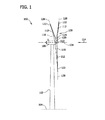
図1は、例示的な風力タービン100の概略図である。例示的実施形態において、風力タービン100は水平軸風力タービンである。或いは、風力タービン100は垂直軸風力タービンである。例示的実施形態において、風力タービン100は接地面104から延在し、接地面104に連結されたタワー102を含む。タワー102は、例えば、アンカーボルトによって、又は基礎取付片を介して(どちらも示さず)接地面104に連結される。ナセル106はタワー102に連結され、ロータ108はナセル106に連結される。ロータ108は、回転ハブ110と、ハブ110に連結された複数のロータブレード112とを含む。例示的実施形態において、ロータ108は3つのロータブレード112を含む。或いは、ロータ108は、風力タービン100が本明細書に記載のように機能できる任意の適切な数のロータブレード112を有する。タワー102は、風力タービン100が本明細書に記載のように機能できる任意の適切な高さ及び/又は構造を有する。
FIG. 1 is a schematic diagram of an
ロータブレード112はハブ110の周りで離間配置されてロータ108の回転を促進することによって、風114からの運動エネルギーを有用な機械エネルギーに、続いて電気エネルギーに変換する。ロータ108及びナセル106は、ヨー軸116を中心にタワー102の周りを回転して、風114の方向に対してロータブレード112の釣り合いを制御する。ロータブレード112は、複数の荷重伝達領域120においてロータブレード根元部分118をハブ110に連結することによってハブ110に嵌合する。荷重伝達領域120は各々が、ハブ荷重伝達領域及びロータブレード荷重伝達領域(両方とも図1には示さず)を有する。ロータブレード112に誘起された荷重は、荷重伝達領域120を介してハブ110に伝達される。各々のロータブレード112は、ロータブレード先端部分122を更に含む。
The
例示的実施形態において、ロータブレード112は、約30メートル(m)(99フィート(ft))〜約120m(394ft)の長さを有する。或いは、ロータブレード112は、風力タービン100が本明細書に記載のように機能できる任意の適切な長さを有する。例えば、ロータブレード112は30m以下又は120m以上の適切な長さを有する。風114がロータブレード112と接触すると、ロータブレード112に揚力が誘起され、ロータブレード先端部分122が加速するにつれて回転軸124の周りでロータ108の回転が誘導される。
In the exemplary embodiment,
ロータブレード112のピッチ角(図示せず)、即ち、風114の方向に対してロータブレード112の釣り合いを決定する角度は、ピッチアセンブリ(図1には示さず)によって変化させる。より詳細には、ロータブレード112のピッチ角を増加させることによって風114にさらされるロータブレード表面積124の量を減少させるか、反対に、ロータブレード112のピッチ角を減少させることによって風114にさらされるロータブレード表面積126の量を増加させる。ロータブレード112のピッチ角は、各々のロータブレード112においてピッチ軸128の周りで調整される。例示的実施形態において、ロータブレード112のピッチ角は個別に制御される。
The pitch angle of the rotor blade 112 (not shown), that is, the angle that determines the balance of the
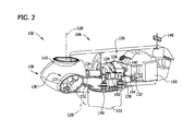
図2は、風力タービン100で使用されるナセル106の部分断面図である。例示的実施形態において、風力タービン100の様々な構成要素がナセル116に収容される。例えば、例示的実施形態において、ナセル106はピッチアセンブリ130を含む。各々のピッチアセンブリ130は関連するロータブレード112(図1に示す)に連結され、ピッチ軸128の周りで関連するロータブレード112のピッチを調節する。例示的実施形態において、各々のピッチアセンブリ130は少なくとも1つのピッチ駆動モータ131を含む。
FIG. 2 is a partial cross-sectional view of the
更に、例示的実施形態において、ロータ108は、ロータ軸134(主軸又は低速軸とも呼ばれることがある)、ギアボックス136、高速軸138、及び連結器140を介して、ナセル106内に配置された発電機132に回転可能に連結される。ロータ軸134の回転によりギアボックス136を回転可能に駆動し、これが続いて高速軸138を駆動する。高速軸138は連結器140を介して発電機132を回転可能に駆動し、高速軸138の回転は発電機132による電力の生産を促進する。ギアボックス136は支持体142によって支持され、発電機132は支持体144によって支持される。例示的実施形態において、ギアボックス136は二重経路形態を使用して高速軸138を駆動する。或いは、ロータ軸134は、連結器140を介して発電機132に直接連結される。
Further, in the exemplary embodiment, the
ナセル106は、ヨー軸116の周りでナセル106及びロータ108を回転させて風114の方向に対するロータブレード112の釣り合いを制御するヨー駆動機構146を更に含む。ナセル106は少なくとも1つの気象マスト148を更に含み、これは一実施形態では風向風速計を含む(どちらも図2には示さず)。一実施形態において、気象マスト148は、風向き及び/又は風速を含む情報をタービン制御システム150に提供する。タービン制御システム150は、制御アルゴリズムを実行するように構成された1つ又は複数の制御装置或いはその他の処理装置を含む。本明細書において使用される場合、「処理装置」という用語は、システムとマイクロコントローラ、縮小命令セット回路(RISC)、特定用途向け集積回路(ASIC)、プログラマブル論理回路(PLC)、及び本明細書に記載の機能を実行できる任意のその他の回路を含む、任意のプログラマブルシステムを包含する。上記の例は単なる例示であり、従って、いかなる形であれ処理装置という用語の定義及び/又は意味を限定することを意図するものではない。更に、タービン制御システム150は、SCADA(監視制御データ収集)プログラムを実行する。
The
ピッチアセンブリ130は、タービン制御システム150に動作可能に連結される。例示的実施形態において、ナセル106は前部支持軸受152及び後部支持軸受154を更に含む。前部支持軸受152及び後部支持軸受154は、ロータ軸134の半径方向支持及び位置合わせを円滑にする。前部支持軸受152は、ハブ110付近でロータ軸134に連結される。後部支持軸受154は、ギアボックス136及び/又は発電機132の付近でロータ軸134上に配置される。ナセル106は、風力タービン100が本明細書に記載のように機能できる任意の数の支持軸受を含む。ロータ軸134、発電機132、ギアボックス136、高速軸138、連結器140、並びに、支持体142、支持体144、前部支持軸受152、及び後部支持軸受154を含むがこれに限らない任意の関連する締結具、支持体、及び/又は固定装置は、駆動列156と呼ばれることもある。
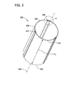
図3は、タワー102(図1に示す)の少なくとも一部を組み立てるのに用いることができる例示的なタワーセクション200の斜視図である。図4は、タワーセクション200の一部の範囲4に沿った拡大斜視図である。例示的実施形態において、タワーセクション200は複数の円弧状セクションパネル202から形成される。或いは、タワーセクション200は単一の一体パネル(図示せず)から形成される。タワーセクション200は、それを通って延在する重心軸204を含む。タワーセクション200は円錐形として図示されているが、タワーセクション200は、タワー102が本明細書に記載のように機能できる、円筒形状又は多角形状を含むがこれに限定されるものではない任意の形状を有してもよい。同様に、セクションパネル202は、本明細書に明確に記載された形状の他に様々な形状を有する。例えば、多角形状タワーセクション200では、セクションパネル202は1つ又は複数の平面を有して形成される。例示的実施形態において、各々のセクションパネル202は第1の円周端206及び対向する第2の円周端208を有する。セクションパネル202は、炭素鋼等の様々な材料で形成される。タワー、例えばタワー102内で、少なくとも1つのタワーセクション200は、セクションパネル202によって少なくとも部分的に画定される、タワー102の内部空洞への接近を可能にする入口通路(図示せず)を有して形成される。タワーセクション200及び各々のセクションパネル202は、第1の軸方向端210から第2の軸方向端212まで、第1の軸方向端210と第2の軸方向端212との間に画定される軸長L1にわたって延在する。
FIG. 3 is a perspective view of an
例示的実施形態において、円周方向に隣接するパネル202は少なくとも1つのコネクタ214を用いて連結されてタワーセクション200を形成する。セクションパネル202の構造及び/又は形状に応じて、後で詳しく述べるように、コネクタ214を変えることもできる。例示的実施形態において、各々のコネクタ214は、外側フランジ302、対向する内側フランジ304、並びにフランジ302及び304の間に延在するスペーサ306を含む。具体的には、例示的実施形態において、外側フランジ302、内側フランジ304、及びスペーサ306は、第1のスロット308及び第2のスロット310がコネクタ214内に画定されるように配向される。より詳細には、例示的実施形態において、スペーサ306は、スロット308及び310が画定されるように、フランジ302及び304が間隔D1を空けて半径方向に離間配置されることを確実にする。一実施形態では、コネクタ214は、セクションパネル202を製造するのに用いられるのと同じ材料、例えば炭素鋼から製造される。或いは、コネクタ214は、セクションパネル202とは異なる材料、及び/又はタワー102及びタワーセクション200が本明細書に記載のように機能できる任意の材料から製造される。
In the exemplary embodiment, circumferentially
コネクタ214は、コネクタ214がセクションパネル202を連結できる継手(図示せず)又は任意の適切な接続機構を含む。更に、コネクタ214は、一体コネクタとして製造してもよく、別個のコネクタ構成要素として製造してもよい。例示的実施形態において、各々のコネクタ214は2つのT字状部分312及び314から形成される。より詳細には、例示的実施形態において、セクションパネル202は円弧状であり、T字状部分312及び314もまた円弧状であってセクションパネル202の収容を円滑にする。或いは、T字状部分312及び314は、角張っていても平面的であってもよく、又はタワー102及びタワーセクション200が本明細書に記載のように機能できる任意のその他の断面形状であってもよい。例示的実施形態において、各々のT字状部分312及び314は、スペーサ延長部316及びフランジ延長部318を有して形成される。
組立の際に、第1のT字状部分312のスペーサ延長部316は、スロット308及び310が各々のT字状部分312及び314のフランジ延長部318の間に画定されるように第2のT字状部分314のスペーサ延長部316と反対方向にある。T字状部分312及び314は、後で詳しく述べるように、セクションパネル202がスロット308及び/又は310に挿入される前又は後に連結される。スペーサ延長部316を互いに連結するために任意の適切な締結機構又は技術を使用する。コネクタ214は、異なる構成から形成することもできる。例えば、一実施形態では、一方のT字状部分だけがスペーサ延長部を含み、他方のT字状部分がフランジ延長部だけを含む。更に、代替的実施形態では、コネクタ214はスペーサ306を含まず、外側プレート及び内側プレート(どちらも示さず)を含む。そのような実施形態では、隣接するセクションパネル202は互いに接触するか又は間に隙間があり、パネル202、外側プレート、及び内側プレートがボルト、溶接部、又はリベット等の任意の適切な連結手段を用いて連結させられる前に、外側プレートと内側プレートとの間に配置される。更なる代替的実施形態では、セクションパネル202は、外側プレート又は内側プレートだけを用いて連結される。
During assembly, the
例示的実施形態において、各々のコネクタ214は、それを通って延在する内部に画定された複数の開口330を含む。開口330は円周方向列に配向されているように図示されているが、タワーセクション200の強度及び構造的完全性を維持しながら、コネクタ214が隣接するセクションパネル202を連結できる任意の数の開口330及び/又は任意の配向の開口330を使用してもよい点に留意する必要がある。より詳細には、例示的実施形態において、開口330は、各々のコネクタ214の第1の端部334から各々のコネクタの第2の端部336まで延在する一対の円周方向列332に画定される。更に、例示的実施形態において、コネクタのT字状部分314はT字状部分312の半径方向内側にあり、T字状部分314内に画定された開口330はT字状部分312内に画定された開口330と実質的に同心円状に整列する。更に、開口330は、後で詳しく述べるように、セクションパネル202をコネクタ214にしっかりと連結させることができるボルト及び/又は別の適切な締結具をそこに収容するように寸法決め及び配向される。代替的実施形態では、コネクタ214は開口330ではなく、セクションパネル202をコネクタ214に連結するために使用される溶接部及び/又はリベット(図示せず)を含む。例示的実施形態において、コネクタ214内で各々の列332に画定された開口330は、同じ直径D2及び形状を有して形成される。或いは、1つの列332の開口330は、隣接する列332の開口330とは異なる直径D2及び/又は形状を有する。
In the exemplary embodiment, each
各々のコネクタ214は、隣接するセクションパネル202を連結させてタワーセクション200を形成するように寸法決め及び配向される。一実施形態では、セクションパネル202はコネクタ214にしっかりと連結される。或いは、セクションパネル202はコネクタ214に取り外し可能に連結される。例示的実施形態において、セクションパネル202は各々が、内部に画定された複数の開口342を含む。パネルの開口342は、コネクタの開口330と整列するように寸法決め及び配向される。具体的には、例示的実施形態において、開口342は、各々が円周端206及び208と実質的に平行に延在する一対の略平行列に配向される。タワーセクション200の組立中、第1のセクションパネル202の第1の円周端206はコネクタの第1のスロット308に挿入され、第2のセクションパネル202の第2の円周端208はコネクタの第2のスロット310に挿入される。各々の円周端206及び208が各コネクタのスロット308及び310に挿入された後、パネルの開口342はコネクタ214内に画定された開口330に対して実質的に同心円状に整列する。従って、ボルト等の適切な締結具は、締結具がフランジ延長部318を通って、更にパネルの円周端206及び208を通って延在してセクションパネル202をしっかりと連結させることができるように開口330及び342から挿入できる。例示的実施形態において、締結具はセクションの重心軸204に対して略半径方向に延在する。
Each
例示的実施形態において、各々のコネクタ214は端部334及び336間で測った軸長L2を有しており、これは各々のセクションパネル202の軸長L1とほぼ同じである。従って、例示的実施形態において、各々のコネクタ214は、パネルの円周端206及び208の全軸長L1に沿って延在する。或いは、コネクタ214はパネルの円周端206及び208の軸長L1の一部を覆うだけである。そのような代替的実施形態では、複数のコネクタ214は、パネルの円周端206及び208の全軸長L1に沿って端から端まで連結される。或いは、そのような実施形態では、コネクタ214は軸長L1に沿って離間配置される。
In the exemplary embodiment, each
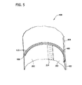
図5は、タワー102(図1に示す)の少なくとも一部を組み立てるのに用いることができる代替的なタワーセクション400の一部の斜視断面図である。例示的実施形態において、タワーセクション400は、タワーセクション200(図3に示す)に関して本明細書に記載したようにセクションパネル202から形成される円錐形タワーセクションである下部タワーセクション402と、一体セクションである上部タワーセクション404とを含む。或いは、下部タワーセクション402は、一体的なタワーセクション(図示せず)とは対照的にセクションパネル202から形成される別のタワーセクション404に連結される。一実施形態では、タワー102の安定性及び剛性の向上を促進するために、各々がセクションパネル202から形成される2つのタワーセクション200を連結させる場合、タワーセクション200上のコネクタ214が互いに垂直には整列しないようにタワーセクション200を配向する。
FIG. 5 is a perspective cross-sectional view of a portion of an
例示的実施形態において、上部タワーセクション404は環状で略平面である下側フランジ408を含み、下部タワーセクション402は環状で略平面である上側フランジ406を含む。更に、例示的実施形態において、各々のフランジ406及び408は略円形である。フランジ406及び408は各々が内部に画定された複数の開口410を含み、それらはそこから複数の締結具(図示せず)を収容して上側フランジ406を下側フランジ408にしっかりと連結できるように寸法決め及び配向される。代替的実施形態では、フランジ406及び408をしっかりと連結させるために溶接部又はリベットを使用することもできる。フランジ406及び/又は408はセクションパネル202と一体的に形成してもよく、且つ/又はタワーセクション402及び404に連結させてもよい。更に、フランジ406及び408はタワーセクション402及び404から半径方向内側に延在するように図示されているが、他の実施形態では、フランジ406及び/又は408の少なくとも一部がタワーセクション402及び404から半径方向外側に延在する。
In the exemplary embodiment,
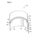
図6は、下部タワーセクション402と上部タワーセクション404との間の代替的な接続部の斜視断面図である。例示的実施形態において、下部タワーセクション402を上部タワーセクション404に連結するために水平コネクタ420が使用される。例示的実施形態において、水平コネクタ420はコネクタ214と同様の構造を有する。より詳細には、水平コネクタ420は、外側フランジ422、対向する内側フランジ424、並びにフランジ422及び424の間に延在するスペーサ426を含む。具体的には、例示的実施形態において、外側フランジ422、内側フランジ424、及びスペーサ426は、下部スロット428及び上部スロット430がコネクタ420内に画定されるように配向される。
FIG. 6 is a perspective cross-sectional view of an alternative connection between the
水平コネクタ420は、コネクタ420が下部タワーセクション402を上部タワーセクション404に連結できる継手(図示せず)又は任意の適切な接続機構を含む。例示的実施形態において、コネクタ420は一体コネクタである。代替的実施形態では、コネクタ420は、互いに連結される、互いに隣り合う、及び/又は互いに離間配置される別個のコネクタ構成要素から製造される。例示的実施形態において、水平コネクタ420は、コネクタ214内の開口330と同様に、それを通って延在する内部に画定された複数の開口440を含む。更に、開口440は、下部タワーセクション402及び上部タワーセクション404を水平コネクタ420にしっかりと連結させることができるボルト及び/又は別の適切な締結具をそこに収容するように寸法決め及び配向される。代替的実施形態では、水平コネクタ420は開口440を備えず、下部タワーセクション402及び上部タワーセクション404を水平コネクタ420(図示せず)に連結するために溶接部及び/又はリベットが使用される。例示的実施形態において、下部タワーセクション402及び上部タワーセクション404は各々が内部に画定された複数の開口450を含む。開口450は、水平コネクタの開口440と整列するように寸法決め及び配向される。
The
下部タワーセクション402を上部タワーセクション404に連結するために、下部タワーセクション402の上縁460が水平コネクタの下部スロット428に挿入され、上部タワーセクション404の下縁462が水平コネクタの上部スロット430に挿入される。上縁460及び下縁462がそれぞれ下部スロット428及び上部スロット430に挿入された後、開口450は水平コネクタ420内に画定された開口440に対して実質的に同心円状に整列する。従って、ボルト等の適切な締結具は、締結具が水平コネクタ420を通って、更に上縁460及び下縁462を通って延在して下部タワーセクション402及び上部タワーセクション404をしっかりと連結させることができるように開口440及び450から挿入できる。
To connect the
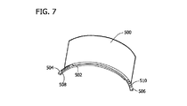
図7は、タワー102の少なくとも一部を組み立てるのに用いることができる例示的なセクションパネル500の斜視図である。例示的実施形態において、セクションパネル500は代替的なセクションコネクタ502を含む。セクションコネクタ502は、セクションパネル500と一体的に形成してもよく、且つ/又は任意のその他の適切な手段を用いてセクションパネル500に連結させてもよい。例示的実施形態において、セクションコネクタ502は実質的に円弧状であり、第1のフランジ部分504及び第2のフランジ部分506を含む。第1のフランジ部分504は、隣接するセクションパネル500から延在する第2のフランジ部分506に連結するように寸法決め及び配向される。例示的実施形態において、第1のフランジ部分504はペグ508を含み、第2のフランジ部分506は、第1のフランジ部分504が隣接するセクションパネル500から延在する第2のフランジ部分506に連結できるように寸法決め及び配向される、対応する開口510を含む。より詳細には、例示的実施形態において、フランジ部分504及び506は実質的に平面であり、第2のフランジ部分506は第1のセクションパネル500から延在し、ペグ508を開口510に挿入してフランジ部分504及び506を連結させる時に第2のセクションパネル500から延在する第1のフランジ部分504に重なり合う。或いは、第1のフランジ部分504及び第2のフランジ部分506は、任意のその他の締結具、及び/或いは溶接部又はリベットを含むがこれに限らない任意の適切な連結手段を用いて連結される。
FIG. 7 is a perspective view of an
セクションコネクタ502を用いてセクションパネル500を連結させてタワーセクションを形成する場合、セクションコネクタ502は上側円形フランジ406及び下側円形フランジ408(共に図5に示す)と同様である環状の略平面フランジ(図示せず)を形成する。例示的実施形態において、セクションコネクタ502は、形成されたフランジにおいて1つのセクションコネクタ502が撓曲して形成されたフランジ上のフープ応力を削減できるように適切に可撓性がある。更に、セクションコネクタ502は一般的に低価格であり、一般的に一体フランジよりも製造し易い。更にまた、好都合にも、そのようなコネクタ502はセクションパネル500と一体的に製造することもできる。
When
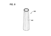
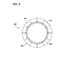
図8は、タワー102(図1に示す)の少なくとも一部を組み立てるのに用いることができる多角形状タワーセクション600の斜視図である。図9は、タワーセクション600の平面図である。例示的実施形態において、タワーセクション600は複数のセクションパネル602から形成される。一実施形態では、タワーセクション600は、各々のセクションパネル602がタワーセクション600の4分の1を形成するように配向される4つのセクションパネル602から形成される。或いは、タワーセクション600は、タワーセクション600が本明細書に記載のように機能できる任意の数のセクションパネル602から形成される。
FIG. 8 is a perspective view of a
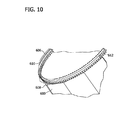
図10は、代替的なタワーセクション606に連結されたセクションパネル602の一部の拡大図である。例示的実施形態において、セクションパネル602は上側フランジ部分608に連結され、タワーセクション606は下側フランジ610に連結される。例示的実施形態において、タワーセクション606は略円筒形であり、下側フランジ610は環状の略平面であって締結具612を用いて上側フランジ部分608に連結される。或いは、下側フランジ610及び上側フランジ部分608は、ボルト、溶接部、又はリベットを含むがこれに限らない任意のその他の適切な連結手段を用いて連結される。
FIG. 10 is an enlarged view of a portion of a
既知の一体的なタワーセクションと比べて、本明細書に記載のモジュラータワーセクションは、セクションパネルが組み立てずに独立して輸送できるので、より大きなタワーセクションの建設を可能にする。更に、セクションパネルは一般的に一体的なタワーセクションよりも低価格で製造し易い。更に、本明細書に記載のコネクタは、スペーサ要素とスロットとが組立中のセクションパネルの位置を固定するので、組立中のセクションパネルの位置合わせの円滑化を向上させる。更に、一体フランジと比べて、本明細書に記載のセクションコネクタは、セクションコネクタが互いに対して可撓性であるので、タワーセクションに引き起こされるフープ応力の削減を促進する。 Compared to known integral tower sections, the modular tower sections described herein allow for the construction of larger tower sections because the section panels can be transported independently without assembly. Furthermore, section panels are generally easier to manufacture at a lower cost than integral tower sections. Further, the connectors described herein improve the smooth alignment of the section panel during assembly because the spacer elements and slots fix the position of the section panel during assembly. Furthermore, compared to integral flanges, the section connectors described herein facilitate reducing hoop stress caused to the tower section because the section connectors are flexible relative to each other.
上記のモジュラータワーセクション及び方法は、改良型モジュラータワーを提供する。タワーセクションは、組み立てずに独立して輸送できるセクションパネル及びコネクタを含むため、現実に輸送可能なものよりも大きなタワーセクションを現場で組み立てることができる。その結果、より高いハブ高さを有するモジュラータワーを建設できる。更に、タワーセクションは、外側フランジ、内側フランジ、及びスペーサを含むコネクタを含んで第1及び第2のスロットを画定する。画定されたスロットは、タワーセクションを形成するためのセクションパネルの配置及び連結を円滑にする。更に、タワーセクションは、互いに連結してフランジを形成する可撓性のセクションコネクタを含む。その結果、形成されたフランジはフープ応力の削減において一体フランジよりも優れている。 The modular tower section and method described above provide an improved modular tower. Because the tower section includes section panels and connectors that can be transported independently without assembly, a larger tower section can be assembled on site than is actually transportable. As a result, a modular tower having a higher hub height can be constructed. In addition, the tower section includes a connector including an outer flange, an inner flange, and a spacer to define first and second slots. The defined slots facilitate the placement and connection of the section panels to form the tower section. In addition, the tower section includes flexible section connectors that connect together to form a flange. As a result, the formed flange is superior to the integral flange in reducing hoop stress.
以上に、モジュラータワー、モジュラータワーセクション、及びモジュラータワーの建設方法の例示的実施形態を詳細に説明した。本明細書に記載の方法及びシステムは本明細書に記載された特定の実施形態には限定されず、むしろ、このシステムの構成要素及び/又はこの方法のステップは本明細書に記載される他の構成要素及び/又はステップとは独立して別個に利用できる。例えば、本明細書に記載の方法及びシステムは、本明細書に記載したように、風力タービンによる実施に限定されないその他の応用例を有する。むしろ、本明細書に記載の方法及びシステムは様々なその他の産業に関して実施及び利用できる。 Above, exemplary embodiments of modular towers, modular tower sections, and modular tower construction methods have been described in detail. The methods and systems described herein are not limited to the specific embodiments described herein, but rather the components of the system and / or the steps of the method are described elsewhere herein. These components and / or steps can be used separately and independently. For example, the methods and systems described herein have other applications that are not limited to implementation with wind turbines, as described herein. Rather, the methods and systems described herein can be implemented and utilized with various other industries.
本発明の様々な実施形態の特定の特徴が、一部の図面には示されており、別の図面には示されていないことがあるが、これは便宜上そうしたに過ぎない。本発明の原理に従って、ある図面の任意の特徴を、その他の図面の任意の特徴と組み合わせて参照し、且つ/又は請求できる。 Although specific features of various embodiments of the invention may be shown in some drawings and not in others, this is for convenience only. In accordance with the principles of the invention, any feature of a drawing may be referenced and / or claimed in combination with any feature of any other drawing.
本明細書は、実施例を使用して、最良の形態を含む本発明を開示し、更にあらゆる装置又はシステムを製作且つ使用すること及びあらゆる組み込まれた方法を実行することを含む本発明の実施を当業者が行なうのを可能にする。本発明の特許性がある技術的範囲は、特許請求の範囲によって規定され、当業者が想到するその他の実施例を含むことができる。そのようなその他の実施例は、それらが特許請求の範囲の文言と相違しない構造的要素を有する場合、又はそれらが特許請求の範囲の文言と本質的でない相違を有する同等な構造的要素を含む場合には、特許請求の範囲の技術的範囲内に属することになるものとする。 This written description uses examples to disclose the invention, including the best mode, and further to make and use any apparatus or system and to implement any incorporated methods. Can be performed by those skilled in the art. The patentable scope of the invention is defined by the claims, and may include other examples that occur to those skilled in the art. Such other embodiments include equivalent structural elements in which they have structural elements that do not differ from the language of the claims, or that they have non-essential differences from the language of the claims. In that case, they shall fall within the technical scope of the claims.
100 風力タービン
102 タワー
104 接地面
106 ナセル
108 ロータ
110 ハブ
112 ロータブレード
114 風
116 ヨー軸
118 ロータブレード根元部分
120 荷重伝達領域
122 ロータブレード先端部分
124 回転軸
126 ロータブレード表面積
128 ピッチ軸
130 ピッチアセンブリ
131 ピッチ駆動モータ
132 発電機
134 ロータ軸
136 ギアボックス
138 高速軸
140 連結器
142 支持体
144 支持体
146 ヨー駆動機構
148 気象マスト
150 タービン制御システム
152 前部支持軸受
154 後部支持軸受
156 駆動列
200 タワーセクション
202 セクションパネル
204 重心軸
206 第1の円周端
208 第2の円周端
210 第1の軸方向端
212 第2の軸方向端
214 コネクタ
302 外側フランジ
304 内側フランジ
306 スペーサ
308 コネクタの第1のスロット
310 コネクタの第2のスロット
312、314 T字状部分
316 スペーサ延長部
318 フランジ延長部
330 コネクタの開口
332 円周方向列
334 第1の端部
336 第2の端部
342 パネルの開口
400 タワーセクション
402 下部タワーセクション
404 上部タワーセクション
406 上側フランジ
408 下側フランジ
410 開口
420 水平コネクタ
422 外側フランジ
424 内側フランジ
426 スペーサ
428 下部スロット
430 上部スロット
440 水平コネクタの開口
450 開口
460 上縁
462 下縁
500 セクションパネル
502 セクションコネクタ
504 第1のフランジ部分
506 第2のフランジ部分
508 ペグ
510 開口
600 タワーセクション
602 セクションパネル
606 タワーセクション
608 上側フランジ部分
610 下側フランジ
612 締結具
DESCRIPTION OF SYMBOLS 100 Wind turbine 102 Tower 104 Ground surface 106 Nacelle 108 Rotor 110 Hub 112 Rotor blade 114 Wind 116 Yaw shaft 118 Rotor blade root portion 120 Load transmission area 122 Rotor blade tip portion 124 Rotating shaft 126 Rotor blade surface area 128 Pitch shaft 130 Pitch assembly 131 Pitch drive motor 132 Generator 134 Rotor shaft 136 Gear box 138 High speed shaft 140 Coupler 142 Support body 144 Support body 146 Yaw drive mechanism 148 Weather mast 150 Turbine control system 152 Front support bearing 154 Rear support bearing 156 Drive train 200 Tower section 202 Section panel 204 Center of gravity axis 206 First circumferential end 208 Second circumferential end 210 First axial end 212 Second axial end 214 Connector 302 Outer flange 304 Inner flange 306 Spacer 308 Connector first slot 310 Connector second slot 312, 314 T-shaped portion 316 Spacer extension 318 Flange extension 330 Connector opening 332 Circumferential row 334 First One end 336 Second end 342 Panel opening 400 Tower section 402 Lower tower section 404 Upper tower section 406 Upper flange 408 Lower flange 410 Opening 420 Horizontal connector 422 Outer flange 424 Inner flange 426 Spacer 428 Lower slot 430 Upper Slot 440 Horizontal connector opening 450 Opening 460 Upper edge 462 Lower edge 500 Section panel 502 Section connector 504 First flange portion 506 Second flange portion 508 Peg 510 Opening 600 Tower section 602 Section panel 606 Tower section 608 Upper flange portion 610 Lower flange 612 Fastener
Claims (10)
各々が一対の対向する円周端(206、208)を備える複数の組立パネル(202)と、
前記複数の組立パネルの隣接する組立パネルを互いに連結するのに用いられる複数のコネクタ(214)であって、前記複数のコネクタの各々のコネクタが外側フランジ(302)、内側フランジ(304)、及びそれらの間に延在するスペーサ(306)を備え、前記外側フランジは第1のスロット(308)及び第2のスロット(310)が前記外側フランジと前記内側フランジとの間に画定されるように前記内側フランジから間隔を空けて離間配置され、前記第1及び前記第2のスロットの各々は前記隣接する組立パネルを互いに連結させることができるように内部に前記組立パネルの円周端の一方を収容するように寸法決めされる前記複数のコネクタ(214)とを含む、タワーアセンブリ(200)。 A modular tower (102) tower assembly (200) comprising:
A plurality of assembly panels (202) each comprising a pair of opposed circumferential ends (206, 208);
A plurality of connectors (214) used to connect adjacent assembly panels of the plurality of assembly panels together, each connector of the plurality of connectors comprising an outer flange (302), an inner flange (304), and A spacer (306) extending therebetween, wherein the outer flange has a first slot (308) and a second slot (310) defined between the outer flange and the inner flange; The first and second slots are spaced apart from the inner flange, and each of the first and second slots has one of the circumferential ends of the assembly panel inside thereof so that the adjacent assembly panels can be connected to each other. The tower assembly (200) including the plurality of connectors (214) dimensioned to receive.
各々が一対の対向する円周端(206、208)を備える複数のセクションパネル(202)と、
前記複数のセクションパネルの隣接するセクションパネルを互いに連結するのに用いられる複数のコネクタ(214)であって、前記コネクタの各々が外側フランジ(302)、内側フランジ(304)、及びそれらの間に延在するスペーサ(306)を備え、前記外側フランジは第1のスロット(308)及び第2のスロット(310)が前記外側フランジと前記内側フランジとの間に画定されるように前記内側フランジから間隔を空けられ、前記第1及び前記第2のスロットの各々は前記隣接するセクションパネルを互いに連結させることができるように内部に前記セクションパネルの円周端の一方を収容するように寸法決めされる前記複数のコネクタ(214)とを備える前記少なくとも1つの下部タワーセクション(412)と、
前記下部セクションに連結された少なくとも1つの上部タワーセクション(404)とを含む、モジュラータワー(102)。 At least one lower tower section (402),
A plurality of section panels (202) each comprising a pair of opposing circumferential ends (206, 208);
A plurality of connectors (214) used to connect adjacent section panels of the plurality of section panels together, each of the connectors having an outer flange (302), an inner flange (304), and a gap therebetween; A spacer (306) extending from the inner flange such that a first slot (308) and a second slot (310) are defined between the outer flange and the inner flange. Spaced and each of the first and second slots are sized to accommodate one of the circumferential ends of the section panels therein so that the adjacent section panels can be coupled together. Said at least one lower tower section (412) comprising said plurality of connectors (214);
A modular tower (102) comprising at least one upper tower section (404) coupled to the lower section.
第1のフランジ部分(504)と、
前記複数の円弧状コネクタの隣接する1つから延在する第1のフランジ部分に連結するように寸法決め及び配向された第2のフランジ部分(506)とを備える、請求項9に記載のモジュラータワー(102)。 The first annular flange (406) is formed from a plurality of arc-shaped connectors (502), and each of the plurality of arc-shaped connectors includes:
A first flange portion (504);
The modular of claim 9, comprising a second flange portion (506) dimensioned and oriented to connect to a first flange portion extending from an adjacent one of the plurality of arcuate connectors. Tower (102).
Applications Claiming Priority (2)
| Application Number | Priority Date | Filing Date | Title |
|---|---|---|---|
| US13/009,326 US8316615B2 (en) | 2011-01-19 | 2011-01-19 | Modular tower and methods of assembling same |
| US13/009,326 | 2011-01-19 |
Publications (2)
| Publication Number | Publication Date |
|---|---|
| JP2012149643A true JP2012149643A (en) | 2012-08-09 |
| JP2012149643A5 JP2012149643A5 (en) | 2015-02-26 |
Family
ID=44971272
Family Applications (1)
| Application Number | Title | Priority Date | Filing Date |
|---|---|---|---|
| JP2012005763A Pending JP2012149643A (en) | 2011-01-19 | 2012-01-16 | Modular tower and method of assembling the same |
Country Status (10)
| Country | Link |
|---|---|
| US (1) | US8316615B2 (en) |
| EP (1) | EP2481927B1 (en) |
| JP (1) | JP2012149643A (en) |
| KR (1) | KR20120084674A (en) |
| CN (1) | CN102606416B (en) |
| AU (1) | AU2012200301A1 (en) |
| CA (1) | CA2764484C (en) |
| DK (1) | DK2481927T3 (en) |
| ES (1) | ES2575672T3 (en) |
| IN (1) | IN2012DE00144A (en) |
Cited By (1)
| Publication number | Priority date | Publication date | Assignee | Title |
|---|---|---|---|---|
| US10041269B2 (en) * | 2015-04-02 | 2018-08-07 | Arcelormittal | Wind turbine tower section, wind turbine tower and assembly method |
Families Citing this family (35)
| Publication number | Priority date | Publication date | Assignee | Title |
|---|---|---|---|---|
| DK2375057T3 (en) * | 2010-03-31 | 2016-08-15 | Siemens Ag | wind farms |
| ES2366078B1 (en) * | 2010-03-31 | 2012-08-06 | Abengoa Solar New Technologies, S.A. | PRETENSED SOLAR COLLECTOR MODULE. |
| CN102971526A (en) * | 2010-07-12 | 2013-03-13 | 西门子公司 | Tower construction |
| US8209913B2 (en) * | 2011-02-01 | 2012-07-03 | Mitsubishi Heavy Industries, Ltd. | Tubular structure and wind turbine generator |
| EP2525021B8 (en) * | 2011-05-16 | 2018-11-28 | GE Renewable Technologies Wind B.V. | Wind turbine tower supporting structure |
| CN103890387B (en) * | 2011-08-30 | 2016-09-21 | 菱重维斯塔斯海上风力有限公司 | Transition structure for wind turbine tower |
| US20130212963A1 (en) * | 2012-02-21 | 2013-08-22 | Fabcon, Inc. | Wind Turbine Tower |
| CN104379854A (en) * | 2012-04-10 | 2015-02-25 | 帝牌工业制造有限公司 | Utility pole assembly |
| WO2014068592A1 (en) * | 2012-10-31 | 2014-05-08 | Mehra Yogesh Jogindernath | Tower for a wind turbine |
| US9033179B2 (en) * | 2012-11-20 | 2015-05-19 | Vicwest Inc | Water tank |
| EP2806086A1 (en) * | 2013-05-22 | 2014-11-26 | Siemens Aktiengesellschaft | Flange assembly for a tower segment |
| KR101696011B1 (en) * | 2013-06-28 | 2017-01-23 | 주식회사 포스코 | Tower for modular robot wind power generator |
| KR102045580B1 (en) * | 2013-06-28 | 2019-11-15 | 주식회사 포스코 | Modular wind tower |
| KR101696019B1 (en) * | 2014-03-31 | 2017-01-13 | 주식회사 포스코 | Modular wind tower |
| EP3132141B1 (en) | 2014-04-14 | 2018-02-28 | Vestas Wind Systems A/S | Tower segment |
| US10018187B2 (en) | 2014-04-25 | 2018-07-10 | Vestas Wind Systems A/S | Tower section production process |
| CN104314771B (en) * | 2014-09-30 | 2017-04-05 | 新疆大学 | The interchangeable flange connecting apparatus of chunk |
| EP3139037A1 (en) * | 2015-09-02 | 2017-03-08 | Siemens Aktiengesellschaft | Tower for a wind turbine with buttresses |
| US9556615B1 (en) * | 2015-10-13 | 2017-01-31 | The Dragon Group, LLC | Encapsulated panel systems |
| CN105484945B (en) * | 2016-01-12 | 2018-08-28 | 明阳智慧能源集团股份公司 | A kind of polygon wind power tower and its manufacturing method |
| DE102016114114A1 (en) * | 2016-07-29 | 2018-02-01 | Wobben Properties Gmbh | Connecting element for connecting tower sections, tower section, tower, wind turbine and method for producing a tower section and for connecting tower sections |
| US20190211543A1 (en) * | 2016-08-18 | 2019-07-11 | Bull Moose Tube Company | Splice connectors for hollow structural segments and methods of making the same |
| CN106237782A (en) * | 2016-08-22 | 2016-12-21 | 上海二十冶建设有限公司 | The modularity installation method of active carbon desulfurization denitration adsorption tower |
| US10053886B2 (en) * | 2016-11-29 | 2018-08-21 | General Electric Company | Connection assembly for wind turbine tower |
| KR101920371B1 (en) * | 2017-01-11 | 2018-11-21 | 삼우플랜트(주) | Steel pole |
| EP3645872B1 (en) * | 2017-06-30 | 2021-08-04 | Arcelormittal | Wind turbine mast section, wind turbine mast and assembly method |
| DE102017116872A1 (en) * | 2017-07-26 | 2019-01-31 | Wobben Properties Gmbh | Wind turbine steel tower section for a wind turbine tower and process of manufacture |
| CN107654338B (en) * | 2017-09-30 | 2019-09-03 | 新疆金风科技股份有限公司 | Tower section, tower frame, wind turbine and method for manufacturing tower section |
| US20190292803A1 (en) * | 2018-03-26 | 2019-09-26 | General Electric Company | Additively manufactured tower structure and method of fabrication |
| CN108708831A (en) * | 2018-05-16 | 2018-10-26 | 南京风电科技有限公司 | Tower barrel of wind generating set and tower construction method |
| HRP20221479T1 (en) * | 2018-10-30 | 2023-01-20 | Arcelormittal | Wind turbine mast section, wind turbine mast and assembly method |
| HRP20221480T1 (en) * | 2018-10-30 | 2023-01-20 | Arcelormittal | Wind turbine mast section, wind turbine mast and assembly method |
| US20240287967A1 (en) * | 2021-06-30 | 2024-08-29 | Vestas Wind Systems A/S | A segmented wind turbine tower section and method of assembling same |
| CN115109129B (en) * | 2022-06-30 | 2025-05-09 | 国家粮食和物资储备局科学研究院 | An insecticidal protein mutant GNIP1Aa-D420L and its encoding gene and application |
| CN116335887A (en) * | 2022-11-30 | 2023-06-27 | 北京金风科创风电设备有限公司 | Support assembly and wind generating set |
Citations (6)
| Publication number | Priority date | Publication date | Assignee | Title |
|---|---|---|---|---|
| JPH08159115A (en) * | 1994-12-01 | 1996-06-18 | Showa Aircraft Ind Co Ltd | Joint structure between honeycomb panels |
| WO2005028781A2 (en) * | 2003-09-16 | 2005-03-31 | Clement Hiel | Composite tower for a wind turbine and method of assembly |
| US20080041009A1 (en) * | 2006-08-18 | 2008-02-21 | General Electric | Flangeless support structures |
| US20080256892A1 (en) * | 2007-04-17 | 2008-10-23 | Nordex Energy Gmbh | Wind energy plant tower |
| US20090021019A1 (en) * | 2007-06-20 | 2009-01-22 | Siemens Aktiengesellschaft | Wind turbine tower and method for constructing a wind turbine tower |
| JP2010077965A (en) * | 2008-09-25 | 2010-04-08 | General Electric Co <Ge> | Design for flangeless wind power tower |
Family Cites Families (15)
| Publication number | Priority date | Publication date | Assignee | Title |
|---|---|---|---|---|
| US835279A (en) * | 1906-05-07 | 1906-11-06 | Broderick Haskell | Telegraph-pole. |
| US1765946A (en) * | 1928-03-29 | 1930-06-24 | Lou F Knowlton | Tank and joint for forming same |
| US3034209A (en) * | 1956-07-31 | 1962-05-15 | Bianca Edoardo Giuseppe | Method of making tapered tubular sections |
| DE3048051C2 (en) * | 1980-12-19 | 1985-08-29 | Siemens AG, 1000 Berlin und 8000 München | Longitudinally split socket pipe made of thermoplastic material with shape memory |
| NL1019953C2 (en) | 2002-02-12 | 2002-12-19 | Mecal Applied Mechanics B V | Prefabricated tower or mast, as well as a method for joining and / or re-tensioning segments that must form a single structure, as well as a method for building a tower or mast consisting of segments. |
| US7392624B2 (en) * | 2003-02-05 | 2008-07-01 | Dwight Eric Kinzer | Modular load-bearing structural column |
| ATE377707T1 (en) | 2003-03-19 | 2007-11-15 | Vestas Wind Sys As | METHOD FOR MAKING LARGE WIND TURBINE TOWERS |
| US7116282B2 (en) * | 2003-10-14 | 2006-10-03 | John Trankina | Tower reinforcement |
| US7275349B2 (en) * | 2003-10-30 | 2007-10-02 | Barney Auman | Split column reassembly system |
| US7159370B2 (en) * | 2004-01-27 | 2007-01-09 | Reliapole Solutions, Inc. | Modular fiberglass reinforced polymer structural pole system |
| AU2005211457B2 (en) | 2004-02-04 | 2010-03-18 | Corus Staal Bv | Tower for a wind turbine, prefabricated metal wall part for use in a tower for a wind turbine and method for constructing a tower for a wind turbine |
| US7464512B1 (en) | 2004-03-10 | 2008-12-16 | Perina Mark J | Hollow structural member |
| US7360340B2 (en) * | 2005-04-12 | 2008-04-22 | Grundman Curtis M | Means for securing the lower end of a wind turbine tower to a foundation |
| ES2402530T3 (en) * | 2006-01-17 | 2013-05-06 | Vestas Wind Systems A/S | An elevator of a wind turbine tower and a procedure to mount a wind turbine tower |
| CN201443476U (en) * | 2009-06-29 | 2010-04-28 | 山东长星风电科技有限公司 | Tower cylinder for wind power generation |
-
2011
- 2011-01-19 US US13/009,326 patent/US8316615B2/en active Active
-
2012
- 2012-01-16 EP EP12151192.7A patent/EP2481927B1/en active Active
- 2012-01-16 ES ES12151192.7T patent/ES2575672T3/en active Active
- 2012-01-16 DK DK12151192.7T patent/DK2481927T3/en active
- 2012-01-16 JP JP2012005763A patent/JP2012149643A/en active Pending
- 2012-01-17 CN CN201210025634.3A patent/CN102606416B/en active Active
- 2012-01-17 IN IN144DE2012 patent/IN2012DE00144A/en unknown
- 2012-01-17 CA CA2764484A patent/CA2764484C/en active Active
- 2012-01-18 AU AU2012200301A patent/AU2012200301A1/en not_active Abandoned
- 2012-01-18 KR KR1020120005699A patent/KR20120084674A/en not_active Withdrawn
Patent Citations (6)
| Publication number | Priority date | Publication date | Assignee | Title |
|---|---|---|---|---|
| JPH08159115A (en) * | 1994-12-01 | 1996-06-18 | Showa Aircraft Ind Co Ltd | Joint structure between honeycomb panels |
| WO2005028781A2 (en) * | 2003-09-16 | 2005-03-31 | Clement Hiel | Composite tower for a wind turbine and method of assembly |
| US20080041009A1 (en) * | 2006-08-18 | 2008-02-21 | General Electric | Flangeless support structures |
| US20080256892A1 (en) * | 2007-04-17 | 2008-10-23 | Nordex Energy Gmbh | Wind energy plant tower |
| US20090021019A1 (en) * | 2007-06-20 | 2009-01-22 | Siemens Aktiengesellschaft | Wind turbine tower and method for constructing a wind turbine tower |
| JP2010077965A (en) * | 2008-09-25 | 2010-04-08 | General Electric Co <Ge> | Design for flangeless wind power tower |
Cited By (1)
| Publication number | Priority date | Publication date | Assignee | Title |
|---|---|---|---|---|
| US10041269B2 (en) * | 2015-04-02 | 2018-08-07 | Arcelormittal | Wind turbine tower section, wind turbine tower and assembly method |
Also Published As
| Publication number | Publication date |
|---|---|
| AU2012200301A1 (en) | 2012-08-02 |
| US20110283652A1 (en) | 2011-11-24 |
| CN102606416A (en) | 2012-07-25 |
| ES2575672T3 (en) | 2016-06-30 |
| DK2481927T3 (en) | 2016-07-04 |
| CN102606416B (en) | 2017-04-12 |
| EP2481927A1 (en) | 2012-08-01 |
| US8316615B2 (en) | 2012-11-27 |
| EP2481927B1 (en) | 2016-04-13 |
| KR20120084674A (en) | 2012-07-30 |
| CA2764484A1 (en) | 2012-07-19 |
| IN2012DE00144A (en) | 2015-06-05 |
| CA2764484C (en) | 2018-09-04 |
Similar Documents
| Publication | Publication Date | Title |
|---|---|---|
| JP2012149643A (en) | Modular tower and method of assembling the same | |
| US8581464B2 (en) | Segmented rotor | |
| EP2505823B1 (en) | Transport frame for nacelle/rotor hub unit of a wind turbine, method of transporting and mounting a nacelle/rotor hub unit | |
| US8123485B2 (en) | Rotor hub of a wind energy plant | |
| US20130180199A1 (en) | Flange connection for a wind turbine and method of connecting parts of a wind turbine | |
| US20110037271A1 (en) | Wind turbine system and modular wind turbine unit therefor | |
| US20130283722A1 (en) | Transition Structure Between Adjacent Tower Structures | |
| CA2892050C (en) | Wind turbine rotor and methods of assembling the same | |
| KR101042906B1 (en) | Rotor for wind power generator | |
| US20130171002A1 (en) | Hybrid Wind Turbine Tower with Integrated Yaw Bearing System | |
| JP2006077747A (en) | Multiple single-blade wind power generator | |
| EP3023634A1 (en) | A hub for a wind turbine | |
| EP2617991A1 (en) | Vertical axis wind turbine | |
| CN203430702U (en) | Large-torque wind driven generator capable of being overlapped | |
| KR200451756Y1 (en) | Pentagram truss structure for generator and power plant structure using same | |
| CN103397985B (en) | A kind of high-torque cascade type wind turbine generator | |
| WO2024246508A1 (en) | Vertical axis wind turbine | |
| JP2004150314A (en) | Installing structure of wind turbine apparatus | |
| KR101042904B1 (en) | Rotor blades for wind power generators | |
| AU2022304344A1 (en) | Transition piece for a hybrid wind turbine tower and method for assembling same |
Legal Events
| Date | Code | Title | Description |
|---|---|---|---|
| A521 | Request for written amendment filed |
Free format text: JAPANESE INTERMEDIATE CODE: A523 Effective date: 20150113 |
|
| A621 | Written request for application examination |
Free format text: JAPANESE INTERMEDIATE CODE: A621 Effective date: 20150113 |
|
| A977 | Report on retrieval |
Free format text: JAPANESE INTERMEDIATE CODE: A971007 Effective date: 20151029 |
|
| A131 | Notification of reasons for refusal |
Free format text: JAPANESE INTERMEDIATE CODE: A131 Effective date: 20151104 |
|
| A02 | Decision of refusal |
Free format text: JAPANESE INTERMEDIATE CODE: A02 Effective date: 20160329 |