JP2012149209A - Red phosphor, method for producing the same, white light source, illumination device, and liquid crystal display device - Google Patents
Red phosphor, method for producing the same, white light source, illumination device, and liquid crystal display device Download PDFInfo
- Publication number
- JP2012149209A JP2012149209A JP2011108873A JP2011108873A JP2012149209A JP 2012149209 A JP2012149209 A JP 2012149209A JP 2011108873 A JP2011108873 A JP 2011108873A JP 2011108873 A JP2011108873 A JP 2011108873A JP 2012149209 A JP2012149209 A JP 2012149209A
- Authority
- JP
- Japan
- Prior art keywords
- red phosphor
- composition formula
- atomic ratio
- carbon
- red
- Prior art date
- Legal status (The legal status is an assumption and is not a legal conclusion. Google has not performed a legal analysis and makes no representation as to the accuracy of the status listed.)
- Granted
Links
- OAICVXFJPJFONN-UHFFFAOYSA-N Phosphorus Chemical compound [P] OAICVXFJPJFONN-UHFFFAOYSA-N 0.000 title claims abstract description 128
- 239000004973 liquid crystal related substance Substances 0.000 title claims abstract description 30
- 238000005286 illumination Methods 0.000 title claims abstract description 22
- 238000004519 manufacturing process Methods 0.000 title claims abstract description 14
- 239000011575 calcium Substances 0.000 claims abstract description 108
- OKTJSMMVPCPJKN-UHFFFAOYSA-N Carbon Chemical compound [C] OKTJSMMVPCPJKN-UHFFFAOYSA-N 0.000 claims abstract description 54
- 229910052799 carbon Inorganic materials 0.000 claims abstract description 54
- OYPRJOBELJOOCE-UHFFFAOYSA-N Calcium Chemical compound [Ca] OYPRJOBELJOOCE-UHFFFAOYSA-N 0.000 claims abstract description 43
- 229910052791 calcium Inorganic materials 0.000 claims abstract description 43
- IJGRMHOSHXDMSA-UHFFFAOYSA-N Atomic nitrogen Chemical compound N#N IJGRMHOSHXDMSA-UHFFFAOYSA-N 0.000 claims abstract description 38
- QVGXLLKOCUKJST-UHFFFAOYSA-N atomic oxygen Chemical compound [O] QVGXLLKOCUKJST-UHFFFAOYSA-N 0.000 claims abstract description 20
- 239000001301 oxygen Substances 0.000 claims abstract description 20
- 229910052760 oxygen Inorganic materials 0.000 claims abstract description 20
- 229910052757 nitrogen Inorganic materials 0.000 claims abstract description 18
- 229910052693 Europium Inorganic materials 0.000 claims abstract description 16
- XUIMIQQOPSSXEZ-UHFFFAOYSA-N Silicon Chemical compound [Si] XUIMIQQOPSSXEZ-UHFFFAOYSA-N 0.000 claims abstract description 16
- 229910052710 silicon Inorganic materials 0.000 claims abstract description 16
- 239000010703 silicon Substances 0.000 claims abstract description 16
- OGPBJKLSAFTDLK-UHFFFAOYSA-N europium atom Chemical compound [Eu] OGPBJKLSAFTDLK-UHFFFAOYSA-N 0.000 claims abstract description 14
- 229910052712 strontium Inorganic materials 0.000 claims abstract description 12
- CIOAGBVUUVVLOB-UHFFFAOYSA-N strontium atom Chemical compound [Sr] CIOAGBVUUVVLOB-UHFFFAOYSA-N 0.000 claims abstract description 12
- 239000000203 mixture Substances 0.000 claims description 65
- 230000005284 excitation Effects 0.000 claims description 35
- 229920000877 Melamine resin Polymers 0.000 claims description 23
- JDSHMPZPIAZGSV-UHFFFAOYSA-N melamine Chemical compound NC1=NC(N)=NC(N)=N1 JDSHMPZPIAZGSV-UHFFFAOYSA-N 0.000 claims description 23
- 238000001228 spectrum Methods 0.000 claims description 21
- 239000000463 material Substances 0.000 claims description 12
- 229920005989 resin Polymers 0.000 claims description 12
- 239000011347 resin Substances 0.000 claims description 12
- 239000000758 substrate Substances 0.000 claims description 10
- 229910052581 Si3N4 Inorganic materials 0.000 claims description 5
- PSBUJOCDKOWAGJ-UHFFFAOYSA-N azanylidyneeuropium Chemical compound [Eu]#N PSBUJOCDKOWAGJ-UHFFFAOYSA-N 0.000 claims description 5
- 238000010304 firing Methods 0.000 claims description 5
- 238000010298 pulverizing process Methods 0.000 claims description 5
- HQVNEWCFYHHQES-UHFFFAOYSA-N silicon nitride Chemical compound N12[Si]34N5[Si]62N3[Si]51N64 HQVNEWCFYHHQES-UHFFFAOYSA-N 0.000 claims description 5
- 229910052784 alkaline earth metal Inorganic materials 0.000 claims description 4
- 238000005424 photoluminescence Methods 0.000 claims description 4
- -1 Carbonate compound Chemical class 0.000 claims description 3
- 238000010438 heat treatment Methods 0.000 description 22
- 239000000843 powder Substances 0.000 description 10
- 239000002994 raw material Substances 0.000 description 10
- 239000002245 particle Substances 0.000 description 8
- 150000001875 compounds Chemical class 0.000 description 7
- 239000013078 crystal Substances 0.000 description 7
- 238000000295 emission spectrum Methods 0.000 description 7
- 239000012299 nitrogen atmosphere Substances 0.000 description 7
- 239000000126 substance Substances 0.000 description 7
- 241001085205 Prenanthella exigua Species 0.000 description 6
- VYPSYNLAJGMNEJ-UHFFFAOYSA-N Silicium dioxide Chemical compound O=[Si]=O VYPSYNLAJGMNEJ-UHFFFAOYSA-N 0.000 description 6
- 239000004570 mortar (masonry) Substances 0.000 description 6
- BDAGIHXWWSANSR-NJFSPNSNSA-N hydroxyformaldehyde Chemical compound O[14CH]=O BDAGIHXWWSANSR-NJFSPNSNSA-N 0.000 description 5
- 238000000034 method Methods 0.000 description 5
- 238000002156 mixing Methods 0.000 description 5
- 229910000018 strontium carbonate Inorganic materials 0.000 description 5
- 229910052582 BN Inorganic materials 0.000 description 4
- PZNSFCLAULLKQX-UHFFFAOYSA-N Boron nitride Chemical compound N#B PZNSFCLAULLKQX-UHFFFAOYSA-N 0.000 description 4
- VTYYLEPIZMXCLO-UHFFFAOYSA-L Calcium carbonate Chemical compound [Ca+2].[O-]C([O-])=O VTYYLEPIZMXCLO-UHFFFAOYSA-L 0.000 description 4
- CURLTUGMZLYLDI-UHFFFAOYSA-N Carbon dioxide Chemical compound O=C=O CURLTUGMZLYLDI-UHFFFAOYSA-N 0.000 description 4
- 238000010521 absorption reaction Methods 0.000 description 4
- 239000012298 atmosphere Substances 0.000 description 4
- 230000007423 decrease Effects 0.000 description 4
- 238000009616 inductively coupled plasma Methods 0.000 description 4
- 239000011777 magnesium Substances 0.000 description 4
- UCKMPCXJQFINFW-UHFFFAOYSA-N Sulphide Chemical compound [S-2] UCKMPCXJQFINFW-UHFFFAOYSA-N 0.000 description 3
- 238000004458 analytical method Methods 0.000 description 3
- 239000003086 colorant Substances 0.000 description 3
- 238000011156 evaluation Methods 0.000 description 3
- 239000001257 hydrogen Substances 0.000 description 3
- 229910052739 hydrogen Inorganic materials 0.000 description 3
- 125000004435 hydrogen atom Chemical class [H]* 0.000 description 3
- 230000001678 irradiating effect Effects 0.000 description 3
- 229910019655 synthetic inorganic crystalline material Inorganic materials 0.000 description 3
- FYYHWMGAXLPEAU-UHFFFAOYSA-N Magnesium Chemical compound [Mg] FYYHWMGAXLPEAU-UHFFFAOYSA-N 0.000 description 2
- 229910052788 barium Inorganic materials 0.000 description 2
- DSAJWYNOEDNPEQ-UHFFFAOYSA-N barium atom Chemical compound [Ba] DSAJWYNOEDNPEQ-UHFFFAOYSA-N 0.000 description 2
- 229910000019 calcium carbonate Inorganic materials 0.000 description 2
- 229910002092 carbon dioxide Inorganic materials 0.000 description 2
- 239000001569 carbon dioxide Substances 0.000 description 2
- 229910002091 carbon monoxide Inorganic materials 0.000 description 2
- 238000001514 detection method Methods 0.000 description 2
- 238000010586 diagram Methods 0.000 description 2
- 238000004020 luminiscence type Methods 0.000 description 2
- 229910052749 magnesium Inorganic materials 0.000 description 2
- 230000007935 neutral effect Effects 0.000 description 2
- 238000002360 preparation method Methods 0.000 description 2
- 229910052684 Cerium Inorganic materials 0.000 description 1
- 238000003991 Rietveld refinement Methods 0.000 description 1
- 235000005811 Viola adunca Nutrition 0.000 description 1
- 240000009038 Viola odorata Species 0.000 description 1
- 235000013487 Viola odorata Nutrition 0.000 description 1
- 235000002254 Viola papilionacea Nutrition 0.000 description 1
- JNDMLEXHDPKVFC-UHFFFAOYSA-N aluminum;oxygen(2-);yttrium(3+) Chemical compound [O-2].[O-2].[O-2].[Al+3].[Y+3] JNDMLEXHDPKVFC-UHFFFAOYSA-N 0.000 description 1
- 125000004429 atom Chemical group 0.000 description 1
- ZMIGMASIKSOYAM-UHFFFAOYSA-N cerium Chemical compound [Ce][Ce][Ce][Ce][Ce][Ce][Ce][Ce][Ce][Ce][Ce][Ce][Ce][Ce][Ce][Ce][Ce][Ce][Ce][Ce][Ce][Ce][Ce][Ce][Ce][Ce][Ce][Ce][Ce][Ce][Ce][Ce][Ce][Ce][Ce][Ce][Ce][Ce] ZMIGMASIKSOYAM-UHFFFAOYSA-N 0.000 description 1
- 238000002485 combustion reaction Methods 0.000 description 1
- 239000000470 constituent Substances 0.000 description 1
- 238000010276 construction Methods 0.000 description 1
- 230000006866 deterioration Effects 0.000 description 1
- 230000000694 effects Effects 0.000 description 1
- 238000011049 filling Methods 0.000 description 1
- 230000004907 flux Effects 0.000 description 1
- 239000007789 gas Substances 0.000 description 1
- 238000000227 grinding Methods 0.000 description 1
- 230000007062 hydrolysis Effects 0.000 description 1
- 238000006460 hydrolysis reaction Methods 0.000 description 1
- 230000006872 improvement Effects 0.000 description 1
- 238000009413 insulation Methods 0.000 description 1
- 238000004898 kneading Methods 0.000 description 1
- 238000005259 measurement Methods 0.000 description 1
- 238000002844 melting Methods 0.000 description 1
- 230000008018 melting Effects 0.000 description 1
- 238000001745 non-dispersive infrared spectroscopy Methods 0.000 description 1
- 239000002243 precursor Substances 0.000 description 1
- 230000008569 process Effects 0.000 description 1
- 230000009467 reduction Effects 0.000 description 1
- 229910019901 yttrium aluminum garnet Inorganic materials 0.000 description 1
Images


Classifications
-
- C—CHEMISTRY; METALLURGY
- C09—DYES; PAINTS; POLISHES; NATURAL RESINS; ADHESIVES; COMPOSITIONS NOT OTHERWISE PROVIDED FOR; APPLICATIONS OF MATERIALS NOT OTHERWISE PROVIDED FOR
- C09K—MATERIALS FOR MISCELLANEOUS APPLICATIONS, NOT PROVIDED FOR ELSEWHERE
- C09K11/00—Luminescent, e.g. electroluminescent, chemiluminescent materials
- C09K11/08—Luminescent, e.g. electroluminescent, chemiluminescent materials containing inorganic luminescent materials
- C09K11/0883—Arsenides; Nitrides; Phosphides
-
- C—CHEMISTRY; METALLURGY
- C09—DYES; PAINTS; POLISHES; NATURAL RESINS; ADHESIVES; COMPOSITIONS NOT OTHERWISE PROVIDED FOR; APPLICATIONS OF MATERIALS NOT OTHERWISE PROVIDED FOR
- C09K—MATERIALS FOR MISCELLANEOUS APPLICATIONS, NOT PROVIDED FOR ELSEWHERE
- C09K11/00—Luminescent, e.g. electroluminescent, chemiluminescent materials
- C09K11/08—Luminescent, e.g. electroluminescent, chemiluminescent materials containing inorganic luminescent materials
- C09K11/77—Luminescent, e.g. electroluminescent, chemiluminescent materials containing inorganic luminescent materials containing rare earth metals
- C09K11/7728—Luminescent, e.g. electroluminescent, chemiluminescent materials containing inorganic luminescent materials containing rare earth metals containing europium
- C09K11/77347—Silicon Nitrides or Silicon Oxynitrides
-
- G—PHYSICS
- G02—OPTICS
- G02F—OPTICAL DEVICES OR ARRANGEMENTS FOR THE CONTROL OF LIGHT BY MODIFICATION OF THE OPTICAL PROPERTIES OF THE MEDIA OF THE ELEMENTS INVOLVED THEREIN; NON-LINEAR OPTICS; FREQUENCY-CHANGING OF LIGHT; OPTICAL LOGIC ELEMENTS; OPTICAL ANALOGUE/DIGITAL CONVERTERS
- G02F1/00—Devices or arrangements for the control of the intensity, colour, phase, polarisation or direction of light arriving from an independent light source, e.g. switching, gating or modulating; Non-linear optics
- G02F1/01—Devices or arrangements for the control of the intensity, colour, phase, polarisation or direction of light arriving from an independent light source, e.g. switching, gating or modulating; Non-linear optics for the control of the intensity, phase, polarisation or colour
- G02F1/13—Devices or arrangements for the control of the intensity, colour, phase, polarisation or direction of light arriving from an independent light source, e.g. switching, gating or modulating; Non-linear optics for the control of the intensity, phase, polarisation or colour based on liquid crystals, e.g. single liquid crystal display cells
- G02F1/133—Constructional arrangements; Operation of liquid crystal cells; Circuit arrangements
- G02F1/1333—Constructional arrangements; Manufacturing methods
- G02F1/1335—Structural association of cells with optical devices, e.g. polarisers or reflectors
- G02F1/1336—Illuminating devices
- G02F1/133602—Direct backlight
- G02F1/133603—Direct backlight with LEDs
-
- H—ELECTRICITY
- H01—ELECTRIC ELEMENTS
- H01L—SEMICONDUCTOR DEVICES NOT COVERED BY CLASS H10
- H01L33/00—Semiconductor devices with at least one potential-jump barrier or surface barrier specially adapted for light emission; Processes or apparatus specially adapted for the manufacture or treatment thereof or of parts thereof; Details thereof
- H01L33/48—Semiconductor devices with at least one potential-jump barrier or surface barrier specially adapted for light emission; Processes or apparatus specially adapted for the manufacture or treatment thereof or of parts thereof; Details thereof characterised by the semiconductor body packages
- H01L33/50—Wavelength conversion elements
- H01L33/501—Wavelength conversion elements characterised by the materials, e.g. binder
-
- H—ELECTRICITY
- H05—ELECTRIC TECHNIQUES NOT OTHERWISE PROVIDED FOR
- H05B—ELECTRIC HEATING; ELECTRIC LIGHT SOURCES NOT OTHERWISE PROVIDED FOR; CIRCUIT ARRANGEMENTS FOR ELECTRIC LIGHT SOURCES, IN GENERAL
- H05B33/00—Electroluminescent light sources
- H05B33/12—Light sources with substantially two-dimensional radiating surfaces
-
- H—ELECTRICITY
- H01—ELECTRIC ELEMENTS
- H01L—SEMICONDUCTOR DEVICES NOT COVERED BY CLASS H10
- H01L2224/00—Indexing scheme for arrangements for connecting or disconnecting semiconductor or solid-state bodies and methods related thereto as covered by H01L24/00
- H01L2224/01—Means for bonding being attached to, or being formed on, the surface to be connected, e.g. chip-to-package, die-attach, "first-level" interconnects; Manufacturing methods related thereto
- H01L2224/42—Wire connectors; Manufacturing methods related thereto
- H01L2224/47—Structure, shape, material or disposition of the wire connectors after the connecting process
- H01L2224/48—Structure, shape, material or disposition of the wire connectors after the connecting process of an individual wire connector
- H01L2224/4805—Shape
- H01L2224/4809—Loop shape
- H01L2224/48091—Arched
-
- Y—GENERAL TAGGING OF NEW TECHNOLOGICAL DEVELOPMENTS; GENERAL TAGGING OF CROSS-SECTIONAL TECHNOLOGIES SPANNING OVER SEVERAL SECTIONS OF THE IPC; TECHNICAL SUBJECTS COVERED BY FORMER USPC CROSS-REFERENCE ART COLLECTIONS [XRACs] AND DIGESTS
- Y02—TECHNOLOGIES OR APPLICATIONS FOR MITIGATION OR ADAPTATION AGAINST CLIMATE CHANGE
- Y02B—CLIMATE CHANGE MITIGATION TECHNOLOGIES RELATED TO BUILDINGS, e.g. HOUSING, HOUSE APPLIANCES OR RELATED END-USER APPLICATIONS
- Y02B20/00—Energy efficient lighting technologies, e.g. halogen lamps or gas discharge lamps
Abstract
Description
本発明は、赤色蛍光体とその製造方法、さらには赤色蛍光体を用いた白色光源、照明装置、および液晶表示装置に関するものである。 The present invention relates to a red phosphor and a manufacturing method thereof, and further relates to a white light source, an illumination device, and a liquid crystal display device using the red phosphor.
照明装置や液晶表示装置のバックライトには、発光ダイオードで構成された白色光源が用いられている。このような白色光源としては、青色発光ダイオード(以下青色LEDと記す)の発光面側に、セリウムを含むイットリウムアルミニウムガーネット(以下YAG:Ceと記す)蛍光体を配置したものが知られている。 A white light source composed of a light emitting diode is used for a backlight of an illumination device or a liquid crystal display device. As such a white light source, a light source in which an yttrium aluminum garnet (hereinafter referred to as YAG: Ce) phosphor containing cerium is disposed on a light emitting surface side of a blue light emitting diode (hereinafter referred to as a blue LED) is known.
また、この他にも青色LEDの発光面側に緑色と赤色の硫化物蛍光体を配置したものが知られている(例えば、特許文献1参照)。さらに、青紫色または青色で発光するLEDの発光面側に、CaAlSiN3結晶中にMn、Eu等を固溶してなる蛍光物質を、他の蛍光物質と所定割合で組み合わせて配置する構成も提案されている(例えば、特許文献2参照)。 In addition to this, there is known one in which green and red sulfide phosphors are arranged on the light emitting surface side of a blue LED (for example, see Patent Document 1). Furthermore, a configuration is also proposed in which a fluorescent material formed by dissolving Mn, Eu, etc. in a CaAlSiN 3 crystal is combined with other fluorescent materials in a predetermined ratio on the light emitting surface side of an LED emitting blue-violet or blue light. (For example, refer to Patent Document 2).
しかしながら、青色LEDの発光面側にYAG:Ce蛍光体を配置した白色光源では、YAG:Ce蛍光体の発光スペクトルに赤色成分が無いため、青みがかった白色光となり色域が狭い。このため、この白色光源を用いて構成された照明装置では純白色の照明を行うことが困難である。またこの白色光源をバックライトに用いた液晶表示装置では、色再現性の良好な表示を行うことが困難である。 However, a white light source in which a YAG: Ce phosphor is disposed on the light emitting surface side of a blue LED has no red component in the emission spectrum of the YAG: Ce phosphor, resulting in bluish white light and a narrow color gamut. For this reason, it is difficult to perform pure white illumination with an illumination device configured using this white light source. Further, in a liquid crystal display device using this white light source as a backlight, it is difficult to perform display with good color reproducibility.
また、青色LEDの発光面側に緑色と赤色の硫化物蛍光体を配置した白色光源では、硫化物赤色蛍光体の加水分解があるため、輝度が経時的に劣化する。このため、この白色光源を用いて構成された照明装置および液晶表示装置では、輝度の劣化が防止された品質の高い照明や表示を行うことが困難である。 Further, in a white light source in which green and red sulfide phosphors are arranged on the light emitting surface side of the blue LED, the luminance deteriorates with time because of the hydrolysis of the sulfide red phosphor. For this reason, it is difficult for a lighting device and a liquid crystal display device configured using this white light source to perform high-quality lighting and display in which deterioration of luminance is prevented.
さらに、CaAlSiN3結晶中にMn、Eu等を固溶してなる蛍光物質を用いた白色光源では、2種類の蛍光物質を混合して用いる手間があった。 Furthermore, in a white light source using a fluorescent material in which Mn, Eu or the like is dissolved in a CaAlSiN 3 crystal, there is a trouble of using a mixture of two types of fluorescent materials.
本発明は、このような実情に鑑みて提案されたものであり、高効率な赤色蛍光体およびその製造方法を提供すること、この赤色蛍光体を用いることで純白な照明が可能な白色光源および照明装置を提供すること、さらには色再現性の良好な液晶表示装置を提供することを目的とする。 The present invention has been proposed in view of such circumstances, and provides a highly efficient red phosphor and a method for producing the same, a white light source capable of pure white illumination using the red phosphor, and It is an object of the present invention to provide an illumination device and also to provide a liquid crystal display device with good color reproducibility.
本件発明者らは、鋭意検討を行った結果、ユーロピウム(Eu)、シリコン(Si)、炭素(C)、酸素(O)、および窒素(N)を含有する赤色蛍光体において、カルシウム(Ca)およびストロンチウム(Sr)を添加することにより、量子効率を向上させることができることを見出した。 As a result of intensive studies, the present inventors have found that in a red phosphor containing europium (Eu), silicon (Si), carbon (C), oxygen (O), and nitrogen (N), calcium (Ca) It was also found that quantum efficiency can be improved by adding strontium (Sr).
すなわち、本発明に係る赤色蛍光体は、元素A、ユーロピウム(Eu)、シリコン(Si)、炭素(C)、酸素(O)、および窒素(N)を、下記組成式(1)の原子数比で含有する。 That is, the red phosphor according to the present invention contains element A, europium (Eu), silicon (Si), carbon (C), oxygen (O), and nitrogen (N) in the number of atoms of the following composition formula (1). Contained in a ratio.

ただし、組成式(1)中、元素Aは、少なくともカルシウム(Ca)およびストロンチウム(Sr)を含む2族の元素である。また、組成式(1)中、m、x、y、nは、3<m<5、0<x<1、0<y<9、0<n<10なる関係を満たす。
However, in the composition formula (1), the element A is a
また、本発明に係る赤色蛍光体の製造方法は、元素A、ユーロピウム(Eu)、シリコン(Si)、炭素(C)、酸素(O)、および窒素(N)が、組成式(1)の原子数比となるように、元素Aの炭酸化合物、窒化ユーロピウム、窒化シリコン、およびメラミンを混合して混合物とし、前記混合物の焼成と、当該焼成によって得られた焼成物の粉砕とを行う。 In the method for producing a red phosphor according to the present invention, the element A, europium (Eu), silicon (Si), carbon (C), oxygen (O), and nitrogen (N) are represented by the composition formula (1). The carbonic acid compound of element A, europium nitride, silicon nitride, and melamine are mixed to obtain an atomic ratio, and the mixture is fired and the fired product obtained by the firing is pulverized.
また、本発明に係る白色光源は、素子基板上に形成された青色発光ダイオードと、前記青色発光ダイオード上に配置されていて赤色蛍光体と緑色蛍光体とを透明樹脂に混練した混練物とを有し、前記赤色蛍光体は、元素A、ユーロピウム(Eu)、シリコン(Si)、炭素(C)、酸素(O)、および窒素(N)を、組成式(1)の原子数比で含有する。 Further, a white light source according to the present invention includes a blue light emitting diode formed on an element substrate, and a kneaded material that is disposed on the blue light emitting diode and kneaded a red phosphor and a green phosphor in a transparent resin. The red phosphor contains element A, europium (Eu), silicon (Si), carbon (C), oxygen (O), and nitrogen (N) in an atomic ratio of composition formula (1) To do.
また、本発明に係る照明装置は、照明基板上に複数の白色光源が配置され、前記白色光源は、素子基板上に形成された青色発光ダイオードと、前記青色発光ダイオード上に配置されていて赤色蛍光体と緑色蛍光体を透明樹脂に混練した混練物を有し、前記赤色蛍光体は、元素A、ユーロピウム(Eu)、シリコン(Si)、炭素(C)、酸素(O)、および窒素(N)を、組成式(1)の原子数比で含有する。 In the illumination device according to the present invention, a plurality of white light sources are disposed on an illumination substrate, and the white light source is disposed on the element substrate, and the red light is disposed on the blue light-emitting diode. The red phosphor has a kneaded material in which a phosphor and a green phosphor are kneaded in a transparent resin, and the red phosphor includes element A, europium (Eu), silicon (Si), carbon (C), oxygen (O), and nitrogen ( N) is contained in the atomic ratio of the composition formula (1).
また、本発明に係る液晶表示装置は、液晶表示パネルと、前記液晶表示パネルを照明する複数の白色光源を用いたバックライトとを有し、前記白色光源は、素子基板上に形成された青色発光ダイオードと、前記青色発光ダイオード上に配置されていて赤色蛍光体と緑色蛍光体を透明樹脂に混練した混練物を有し、前記赤色蛍光体は、元素A、ユーロピウム(Eu)、シリコン(Si)、炭素(C)、酸素(O)、および窒素(N)を、組成式(1)の原子数比で含有する。 The liquid crystal display device according to the present invention includes a liquid crystal display panel and a backlight using a plurality of white light sources that illuminate the liquid crystal display panel, and the white light source is a blue color formed on an element substrate. A light-emitting diode, and a kneaded material arranged on the blue light-emitting diode and kneaded with a red phosphor and a green phosphor in a transparent resin, the red phosphor comprising element A, europium (Eu), silicon (Si ), Carbon (C), oxygen (O), and nitrogen (N) are contained in the atomic ratio of the composition formula (1).
本発明に係る赤色蛍光体は、上述した特徴により、赤色波長帯(例えば、620nm〜770nmの波長帯)に発光ピーク波長を有し、高効率に赤色を発光することができる。 The red phosphor according to the present invention has an emission peak wavelength in a red wavelength band (for example, a wavelength band of 620 nm to 770 nm) and can emit red light with high efficiency due to the above-described characteristics.
また、本発明に係る白色光源は、高効率な赤色蛍光体を用いているため、この赤色蛍光体による赤色光、緑色蛍光体による緑色光、および青色発光ダイオードによる青色光の3原色により、色域が広く明るい白色光を得ることができる。 In addition, since the white light source according to the present invention uses a highly efficient red phosphor, the three primary colors of the red light by the red phosphor, the green light by the green phosphor, and the blue light by the blue light emitting diode are used. A wide area and bright white light can be obtained.
また、本発明に係る照明装置は、色域が広くて明るい白色光源を用いているため、輝度の高い純白色の照明を行うことができる。 Moreover, since the illuminating device according to the present invention uses a bright white light source with a wide color gamut, it can perform pure white illumination with high luminance.
また、本発明に係る液晶表示装置は、液晶表示パネルを照明するバックライトに色域が広くて明るい白色光源を用いて液晶表示パネルを照明するため、液晶表示パネルの表示画面において輝度の高い純白色を得ることができ、色再現性に優れた画質の高い表示を行うことができる。 The liquid crystal display device according to the present invention illuminates the liquid crystal display panel using a bright white light source with a wide color gamut for the backlight that illuminates the liquid crystal display panel. White can be obtained, and display with high image quality with excellent color reproducibility can be performed.
以下、本発明の実施の形態について、図面を参照しながら下記順序にて詳細に説明する。
1.赤色蛍光体の構成
2.赤色蛍光体の製造方法
3.白色光源の構成例
4.照明装置の構成例
5.液晶表示装置の構成例
6.実施例
Hereinafter, embodiments of the present invention will be described in detail in the following order with reference to the drawings.
1. 1. Configuration of
<1.赤色蛍光体の構成>
本発明の一実施の形態に係る赤色蛍光体は、元素A、ユーロピウム(Eu)、シリコン(Si)、炭素(C)、酸素(O)、および窒素(N)を、下記組成式(1)の原子数比で含有する。
<1. Configuration of red phosphor>
A red phosphor according to an embodiment of the present invention includes element A, europium (Eu), silicon (Si), carbon (C), oxygen (O), and nitrogen (N) represented by the following composition formula (1). In the atomic ratio.
ただし、組成式(1)中、元素Aは、少なくともカルシウム(Ca)およびストロンチウム(Sr)を含む2族の元素である。また、組成式(1)中、m、x、y、nは、3<m<5、0<x<1、0<y<9、0<n<10なる関係を満たす。また、Caの原子数比をα、Srの原子数比をβ、その他の2族元素(マグネシウム(Mg)、バリウム(Ba))の原子数比をγとしたとき、m=α+β+γ、0<α/(α+β)<1を満たす。
However, in the composition formula (1), the element A is a
この組成式(1)は、シリコンと炭素の合計の原子数比を9に固定して示したものである。また、組成式(1)中の窒素(N)の原子数比[12−2(n−m)/3]は、組成式(1)内における各元素の原子数比の和が中性になるように計算されている。つまり、組成式(1)における窒素(N)の原子数比をδとし、組成式(1)を構成する各元素の電荷が補償されるとした場合、2(m−x)+2x+4×9−2n−3δ=0となる。これにより、窒素(N)の原子数比δ=12−2(n−m)/3と算出される。 This composition formula (1) is shown with the total atomic ratio of silicon and carbon fixed to 9. In addition, the atomic ratio [12-2 (nm) / 3] of nitrogen (N) in the composition formula (1) is neutral when the sum of the atomic ratio of each element in the composition formula (1) is neutral. It is calculated to be. That is, when the atomic ratio of nitrogen (N) in the composition formula (1) is δ and the charge of each element constituting the composition formula (1) is compensated, 2 (mx) + 2x + 4 × 9− 2n−3δ = 0. Accordingly, the atomic ratio of nitrogen (N) is calculated as δ = 12-2 (nm) / 3.
また、この組成式(1)で表わされる赤色蛍光体は、斜方晶系空間点群Pmn21に属する結晶構造で構成され、構成元素の一つに炭素(C)を含む。炭素が含まれることによって、生成過程での余剰な酸素(O)を取り除き、酸素量を調整する機能を果たす。 The red phosphor represented by the composition formula (1) is composed of a crystal structure belonging to the orthorhombic space point group Pmn21, and contains carbon (C) as one of the constituent elements. By containing carbon, it functions to remove excess oxygen (O) in the production process and adjust the amount of oxygen.
このような赤色蛍光体によれば、元素Aとして、カルシウム(Ca)を含有せず、ストロンチウム(Sr)を含有する赤色蛍光体に比べて、量子効率を向上させることができる。 According to such a red phosphor, the quantum efficiency can be improved as compared with a red phosphor containing no strontium (Sr) as the element A and not containing calcium (Ca).
また、組成式(1)において、α/(α+β)およびyは、α/(α+β)を横軸とし、発光量積分値を縦軸とした場合、測定値の近似直線の傾きが正となる関係を満たすことが好ましい。具体的には、カルシウム(Ca)の含有量(α/(α+β))の増加に伴い、炭素(C)の含有量(y)を増加させることにより、カルシウム(Ca)の含有量(α/(α+β))の増加とともに発光量積分値も高くなり、上記近似直線の傾きを正とすることができる。すなわち、カルシウム(Ca)の含有量の増加に伴い、良好な発光効率を得るために蛍光体に含有すべき炭素(C)の含有量が増加するものと思われる。 In the composition formula (1), α / (α + β) and y have a positive slope of the approximate straight line of the measured value when α / (α + β) is the horizontal axis and the light emission amount integrated value is the vertical axis. It is preferable to satisfy the relationship. Specifically, as the content of calcium (Ca) (α / (α + β)) increases, the content of calcium (Ca) (α / As the (α + β)) increases, the integrated amount of light emission also increases, and the slope of the approximate line can be made positive. That is, with the increase in the content of calcium (Ca), the content of carbon (C) that should be contained in the phosphor in order to obtain good luminous efficiency is considered to increase.
また、組成式(1)中、0<α/(α+β)≦0.2なる関係を満たすことが好ましい。カルシウム(Ca)の含有量(α/(α+β))が20%を超えると、高い発光量積分値を得るために、炭素(C)の含有量(y)も大きくしなければならず、高い発光量積分値を得るのが困難となる。 In the composition formula (1), it is preferable to satisfy the relationship of 0 <α / (α + β) ≦ 0.2. If the calcium (Ca) content (α / (α + β)) exceeds 20%, the carbon (C) content (y) must also be increased in order to obtain a high integrated value of light emission, which is high. It becomes difficult to obtain an integrated value of light emission amount.
また、組成式(1)中、0.012≦y≦0.10なる関係を満たすことが好ましい。炭素(C)の含有量(y)が0.10を超えると、高い発光量積分値を得るのが困難となる。また、赤色蛍光体中における炭素の含有量を測定するための基準となる検出限界(約0.007)を超える0.012以上であれば、他の元素との比率を調整することで、炭素の効果、すなわち、発光効率の向上が実現できる。 Further, in the composition formula (1), it is preferable to satisfy the relationship of 0.012 ≦ y ≦ 0.10. If the content (y) of carbon (C) exceeds 0.10, it will be difficult to obtain a high integrated value of light emission. Moreover, if it is 0.012 or more exceeding the detection limit (about 0.007) which is a reference for measuring the carbon content in the red phosphor, the ratio of carbon to other elements can be adjusted by adjusting the ratio with other elements. The effect of the above, that is, the improvement of luminous efficiency can be realized.
また、PLE(Photoluminescence Excitation)スペクトルにおいて、励起波長400nmの発光強度を1としたときにおける励起波長550nmの発光強度の相対値が0.82以下であることが好ましい。PLEスペクトルにおいて、励起波長400nmの発光強度を1としたときにおける励起波長550nmの発光強度の相対値は、良好な発光効率を得るために蛍光体に含有すべき炭素(C)の含有量と関係し、その相対値が0.82以下、好ましくは0.82以下0.70以上の範囲であることにより、高い発光量積分値を得ることができる。 In the PLE (Photoluminescence Excitation) spectrum, it is preferable that the relative value of the emission intensity at the excitation wavelength of 550 nm when the emission intensity at the excitation wavelength of 400 nm is 1 is 0.82 or less. In the PLE spectrum, when the emission intensity at an excitation wavelength of 400 nm is 1, the relative value of the emission intensity at an excitation wavelength of 550 nm is related to the content of carbon (C) that should be contained in the phosphor in order to obtain good emission efficiency. In addition, when the relative value is within a range of 0.82 or less, preferably 0.82 or less and 0.70 or more, a high light emission amount integrated value can be obtained.
<2.赤色蛍光体の製造方法>
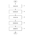
次に、本発明の一実施の形態に係る赤色蛍光体の製造方法を、図1に示すフローチャートによって以下に説明する。
<2. Manufacturing method of red phosphor>
Next, a method for manufacturing a red phosphor according to an embodiment of the present invention will be described below with reference to the flowchart shown in FIG.
図1に示すように、最初に「原料混合工程」S1を行う。この原料混合工程では、まず、組成式(1)を構成する元素を含む原料化合物ととともに、メラミン(C3H6N6)を原料として用いて混合する。 As shown in FIG. 1, first, a “raw material mixing step” S1 is performed. In this raw material mixing step, first, melamine (C 3 H 6 N 6 ) is mixed as a raw material together with a raw material compound containing an element constituting the composition formula (1).
組成式(1)を構成する元素を含む原料化合物としては、元素Aの炭酸化合物[例えば、炭酸ストロンチウム(SrCO3)、炭酸カルシウム(CaCO3)]、窒化ユーロピウム(EuN)、窒化シリコン(Si3N4)を用意する。そして、用意した各原料化合物に含まれる組成式(1)の元素が、組成式(1)の原子数比となるように、各化合物を所定のモル比に秤量する。秤量した各化合物を混合して混合物を生成する。また、メラミンは、フラックスとして、炭酸ストロンチウム、窒化ユーロピウム、および窒化シリコンの全モル数の合計に対して所定割合で添加する。 As a raw material compound containing an element constituting the composition formula (1), a carbonate compound of element A [eg, strontium carbonate (SrCO 3 ), calcium carbonate (CaCO 3 )], europium nitride (EuN), silicon nitride (Si 3) N 4 ) is prepared. Then, each compound is weighed in a predetermined molar ratio so that the element of composition formula (1) contained in each prepared raw material compound has the atomic ratio of composition formula (1). Each weighed compound is mixed to form a mixture. Melamine is added as a flux at a predetermined ratio with respect to the total number of moles of strontium carbonate, europium nitride, and silicon nitride.
混合物の生成は、例えば、窒素雰囲気中のグローボックス内で、メノウ乳鉢内で混合する。 The mixture is produced, for example, by mixing in an agate mortar in a glow box in a nitrogen atmosphere.
次に、「第1熱処理工程」S2を行う。この第1熱処理工程では、上記混合物を焼成して、赤色蛍光体の前駆体となる第1焼成物を生成する。例えば、窒化ホウ素製坩堝内に上記混合物を入れて、水素(H2)雰囲気中で熱処理を行う。この第1熱処理工程では、例えば、熱処理温度を1400℃に設定し、2時間の熱処理を行う。この熱処理温度、熱処理時間は、上記混合物を焼成できる範囲で、適宜変更することができる。 Next, a “first heat treatment step” S2 is performed. In the first heat treatment step, the mixture is fired to produce a first fired product that becomes a precursor of the red phosphor. For example, the mixture is put in a boron nitride crucible and heat treatment is performed in a hydrogen (H 2 ) atmosphere. In the first heat treatment step, for example, the heat treatment temperature is set to 1400 ° C. and the heat treatment is performed for 2 hours. The heat treatment temperature and heat treatment time can be appropriately changed within a range in which the mixture can be fired.
上記第1熱処理工程では、融点が250℃以下であるメラミンが熱分解される。この熱分解された炭素(C)、水素(H)が炭酸ストロンチウムに含まれる一部の酸素(O)と結合して、炭酸ガス(COもしくはCO2)やH2Oとなる。そして、炭酸ガスやH2Oは、気化されるので、上記第1焼成物の炭酸ストロンチウム中より一部の酸素が取り除かれる。また、分解されたメラミンに含まれる窒素(N)によって、還元と窒化とが促される。 In the first heat treatment step, melamine having a melting point of 250 ° C. or lower is thermally decomposed. The pyrolyzed carbon (C) and hydrogen (H) combine with part of oxygen (O) contained in strontium carbonate to form carbon dioxide (CO or CO 2 ) or H 2 O. Since carbon dioxide gas and H 2 O are vaporized, a part of oxygen is removed from the strontium carbonate of the first fired product. Reduction and nitridation are promoted by nitrogen (N) contained in the decomposed melamine.
次に、「第1粉砕工程」S3を行う。この第1粉砕工程では、上記第1焼成物を粉砕して第1粉末を生成する。例えば、窒素雰囲気中のグローボックス内で、メノウ乳鉢を用いて、上記第1焼成物を粉砕し、その後、例えば#100メッシュ(目開きが約200μm)に通して、平均粒径が3μmもしくはそれ以下の粒径の上記第1焼成物を得る。これにより、次の工程の第2熱処理で生成される第2焼成物に成分むらを生じにくくさせる。 Next, “first crushing step” S3 is performed. In the first pulverization step, the first fired product is pulverized to produce a first powder. For example, in a glow box in a nitrogen atmosphere, the first fired product is pulverized using an agate mortar, and then passed through, for example, # 100 mesh (aperture is about 200 μm) so that the average particle size is 3 μm or more. The first fired product having the following particle size is obtained. Thereby, it is made hard to produce a component nonuniformity in the 2nd baking products produced | generated by the 2nd heat processing of the following process.
次に、「第2熱処理工程」S4を行う。この第2熱処理工程では、上記第1粉末を熱処理して第2焼成物を生成する。例えば、窒化ホウ素製坩堝内に上記第1粉末を入れて、窒素(N2)雰囲気中で熱処理を行う。この第2熱処理工程では、例えば、上記窒素雰囲気を、例えば0.85MPaに加圧し、熱処理温度を1800℃に設定し、2時間の熱処理を行う。この熱処理温度、熱処理時間は、上記第1粉末を焼成できる範囲で、適宜変更することができる。 Next, a “second heat treatment step” S4 is performed. In the second heat treatment step, the first powder is heat treated to produce a second fired product. For example, the first powder is put in a boron nitride crucible and heat treatment is performed in a nitrogen (N 2 ) atmosphere. In the second heat treatment step, for example, the nitrogen atmosphere is pressurized to 0.85 MPa, the heat treatment temperature is set to 1800 ° C., and the heat treatment is performed for 2 hours. The heat treatment temperature and heat treatment time can be appropriately changed within a range where the first powder can be fired.
このような第2熱処理工程を行うことによって、前記組成式(1)で表される赤色蛍光体が得られる。この第2熱処理工程によって得られた第2焼成物(赤色蛍光体)は、組成式(1)で表される均質なものが得られる。 By performing such a second heat treatment step, the red phosphor represented by the composition formula (1) is obtained. The second fired product (red phosphor) obtained by the second heat treatment step is a homogeneous product represented by the composition formula (1).
次に、「第2粉砕工程」S5を行う。この第2粉砕工程では、上記第2焼成物を粉砕して第2粉末を生成する。例えば、窒素囲気中のグローボックス内でメノウ乳鉢を用いて粉砕し、例えば#420メッシュ(目開きが約26μm)を用いて、上記第2焼成物を、例えば平均粒径が3.5μm程度になるまで粉砕する。 Next, “second crushing step” S5 is performed. In the second pulverization step, the second fired product is pulverized to produce a second powder. For example, pulverization is performed using an agate mortar in a glow box in a nitrogen atmosphere, and the second fired product is made, for example, to an average particle diameter of about 3.5 μm using, for example, # 420 mesh (aperture is about 26 μm). Grind until
上記赤色蛍光体の製造方法により、微粉末(例えば平均粒径が3.5μm程度)の赤色蛍光体が得られる。このように赤色蛍光体を粉末化することにより、例えば緑色蛍光体の粉末とともに透明樹脂に混練したときに、均一に混練されるようになる。 By the method for producing a red phosphor, a red phosphor having a fine powder (for example, an average particle diameter of about 3.5 μm) can be obtained. By powdering the red phosphor in this way, for example, when kneaded into a transparent resin together with the green phosphor powder, the red phosphor is uniformly kneaded.
以上により、「原料混合工程」S1において混合した原子数比で各元素を含有する組成式(1)で表される赤色蛍光体を得ることができる。この赤色蛍光体は、以降の実施例で示すように、赤色波長帯(例えば、620nm〜770nmの波長帯)にピーク発光波長を有する。 As described above, the red phosphor represented by the composition formula (1) containing each element at the atomic ratio mixed in the “raw material mixing step” S1 can be obtained. This red phosphor has a peak emission wavelength in a red wavelength band (for example, a wavelength band of 620 nm to 770 nm) as shown in the following examples.
<3.白色光源の構成例>
次に、本発明の一実施の形態に係る白色光源を、図2に示す概略断面図を用いて説明する。
<3. Configuration example of white light source>
Next, a white light source according to an embodiment of the present invention will be described with reference to a schematic cross-sectional view shown in FIG.
図2に示すように、白色光源1は、素子基板11上に形成されたパッド部12上に青色発光ダイオード21を有している。上記素子基板11には、上記青色発光ダイオード21を駆動するための電力を供給する電極13、14が絶縁性を保って形成され、それぞれの電極13、14は、例えばリード線15、16によって上記青色発光ダイオード21に接続されている。
As shown in FIG. 2, the
また、上記青色発光ダイオード21の周囲には、例えば樹脂層31が設けられ、その樹脂層31には、上記青色発光ダイオード21上を開口する開口部32が形成されている。この開口部32には、上記青色発光ダイオード21の発光方向に開口面積が広くなる傾斜面に形成され、その傾斜面には反射膜33が形成されている。つまり、すり鉢状の開口部32を有する樹脂層31において、開口部32の壁面反射膜33で覆われ、開口部32の底面に発光ダイオード21が配置された状態となっている。そして、上記開口部32内に、赤色蛍光体と緑色蛍光体とを透明樹脂に混線した混練物43が、青色発光ダイオード21、を覆おう状態で埋め込まれて白色光源1が構成されている。
In addition, for example, a
上記赤色蛍光体には、上述した組成式(1)で表される赤色蛍光体が用いられる。この赤色蛍光体は、赤色波長帯(例えば、620nm〜770nmの波長帯)でピ一ク発光波長が得られ、発光強度が強く、輝度が高い。そのため、青色LEDの青色光、緑色蛍光体による緑色光、および赤色蛍光体による赤色光からなる光の3原色による色域が広い明るい白色光を得ることができる。 As the red phosphor, the red phosphor represented by the composition formula (1) described above is used. This red phosphor has a peak emission wavelength in a red wavelength band (for example, a wavelength band of 620 nm to 770 nm), has high emission intensity, and high luminance. Therefore, it is possible to obtain bright white light having a wide color gamut by three primary colors including blue light of the blue LED, green light by the green phosphor, and red light by the red phosphor.
<4.照明装置の構成例>
次に、本発明の一実施の形態に係る照明装置を、図3の概略平面図を用いて説明する。
<4. Configuration Example of Lighting Device>
Next, the illuminating device which concerns on one embodiment of this invention is demonstrated using the schematic plan view of FIG.
図3に示すように、照明装置5は、照明基板51上に前記図2を用いて説明した白色光源1が複数配置されている。その配置例は、例えば、図3(A)に示すように、正方格子配列としてもよく、または図3(B)に示すように、1行おきに例えば1/2ピッチずつずらした配列としてもよい。また、ずらすピッチは、1/2に限らず、1/3ピッチ、1/4ピッチであってもよい。さらには、1行ごとに、もしくは複数行(例えば2行)ごとにずらしてもよい。
As shown in FIG. 3, in the
もしくは、図示はしていないが、1列おきに例えば1/2ピッチずつずらした配列としてもよい。また、ずらすピッチは、1/2に限らず、1/3ピッチ、1/4ピッチであってもよい。さらには、1行ごとに、もしくは複数行(例えば2行)ごとにずらしてもよい。すなわち、上記白色光源1のずらし方は、限定されるものではない。
Alternatively, although not shown in the figure, the arrangement may be shifted every other column, for example, by 1/2 pitch. Further, the shifting pitch is not limited to 1/2, and may be 1/3 pitch or 1/4 pitch. Furthermore, you may shift every 1 line or every several lines (for example, 2 lines). That is, the method of shifting the
上記白色光源1は、前記図2を参照して説明したのと同様な構成を有するものである。すなわち、上記白色光源1は、青色発光ダイオード21上に、赤色蛍光体と緑色蛍光体を透明樹脂に混練した混練物43を有するものである。上記赤色蛍光体には、上述した組成式(1)で表される赤色蛍光体が用いられる。
The
また、上記照明装置5は、点発光とほぼ同等の白色光源1が照明基板51上に、縦横に複数配置されていることから、面発光と同等になるので、例えば液晶表示装置のバックライトとして用いることができる。また、通常の照明装置、撮影用の照明装置、工事現場用の照明装置等、種々の用途の照明装置に用いることができる。
Moreover, since the said illuminating
上記照明装置5は、上記白色光源1を用いているため、色域が広い明るい、白色光を得ることができる。例えば、液晶表示装置のバックライトに用いた場合に、表示画面において輝度の高い純白色を得ることができ、表示画面の品質の向上を図ることができる。
Since the illuminating
<5.液晶表示装置の構成例>
次に、本発明の一実施の形態に係る液晶表示装置を、図4の概略構成図を用いて説明する。
<5. Configuration example of liquid crystal display device>
Next, a liquid crystal display device according to an embodiment of the present invention will be described with reference to the schematic configuration diagram of FIG.
図4に示すように、液晶表示装置100は、透過表示部を有する液晶表示パネル110と、その液晶表示パネル110を裏面(表示面とは反対側に面)側に備えたバックライト120とを有する。このバックライト120には、前記図3を参照して説明した照明装置5を用いる。
As shown in FIG. 4, the liquid
上記液晶表示装置100では、バックライト120に上記照明装置5を用いるため、光の3原色による色域が広い明るい白色光で、液晶表示パネル110を照明することができる。よって、液晶表示パネル110の表示画面において輝度の高い純白色を得ることができ、色再現性が良好で表示画面の品質の向上を図ることができる。
In the liquid
<6.実施例>
以下、本発明の実施例について説明する。ここでは、組成の異なる赤色蛍光体を作製し、これら赤色蛍光体の量子効率、発光量積分値、発光強度、ピーク波長、輝度、およびPLE(Photoluminescence Excitation)スペクトルについて評価した。なお、本発明はこれらの実施例に限定されるものではない。
<6. Example>
Examples of the present invention will be described below. Here, red phosphors having different compositions were prepared, and the quantum efficiency, the integrated amount of light emission, the emission intensity, the peak wavelength, the luminance, and the PLE (Photoluminescence Excitation) spectrum of these red phosphors were evaluated. The present invention is not limited to these examples.
[赤色蛍光体の作製]
元素A、ユーロピウム(Eu)、シリコン(Si)、炭素(C)、酸素(O)、および窒素(N)を、下記組成式(1)の原子数比で含有する赤色蛍光体を図1に示すフローチャートを用いて説明した手順に従って以下のように作製した。
[Production of red phosphor]
FIG. 1 shows a red phosphor containing element A, europium (Eu), silicon (Si), carbon (C), oxygen (O), and nitrogen (N) in an atomic ratio of the following composition formula (1). According to the procedure demonstrated using the flowchart shown, it produced as follows.
ただし、組成式(1)中の元素Aは、マグネシウム(Mg)、カルシウム(Ca)、ストロンチウム(Sr)、またはバリウム(Ba)の少なくとも1つである。また、組成式(1)中、m、x、y、nは、3<m<5、0<x<1、0<y<9、0<n<10なる関係を満たす。また、Caの原子数比をα、Srの原子数比をβ、その他の2族元素の原子数比をγとしたとき、m=α+β+γを満たす。
However, the element A in the composition formula (1) is at least one of magnesium (Mg), calcium (Ca), strontium (Sr), or barium (Ba). In the composition formula (1), m, x, y, and n satisfy the relationship of 3 <m <5, 0 <x <1, 0 <y <9, and 0 <n <10. Further, when the atomic ratio of Ca is α, the atomic ratio of Sr is β, and the atomic ratio of
先ず、「原料混合工程」S1を行った。ここでは、炭酸カルシウム(CaCO3)炭酸ストロンチウム(SrCO3)窒化ユーロピウム(EuN)、窒化シリコン(Si3N4)、およびメラミン(C3H6N6)を用意した。用意した各原料化合物を秤量し、窒素雰囲気中のグローボックス内で、メノウ乳鉢内で混合した。 First, the “raw material mixing step” S1 was performed. Here, calcium carbonate (CaCO 3 ), strontium carbonate (SrCO 3 ), europium nitride (EuN), silicon nitride (Si 3 N 4 ), and melamine (C 3 H 6 N 6 ) were prepared. Each prepared raw material compound was weighed and mixed in an agate mortar in a glow box in a nitrogen atmosphere.
次に、「第1熱処理工程」S2を行った。ここでは、窒化ホウ素製坩堝内に上記混合物を入れて、水素(H2)雰囲気中で1400℃、2時間の熱処理を行った。 Next, “first heat treatment step” S2 was performed. Here, the above mixture was put in a boron nitride crucible, and heat treatment was performed at 1400 ° C. for 2 hours in a hydrogen (H 2 ) atmosphere.
次に、「第1粉砕工程」S3を行った。ここでは、窒素雰囲気中のグローボックス内で、メノウ乳鉢を用いて、上記第1焼成物を粉砕し、その後、#100メッシュ(目開きが約200μm)に通して、平均粒径が3μm以下の粒径の第1焼成物を得た。 Next, “first pulverization step” S3 was performed. Here, in a glow box in a nitrogen atmosphere, the first fired product is pulverized using an agate mortar, and then passed through # 100 mesh (aperture is about 200 μm), and the average particle size is 3 μm or less. A first fired product having a particle size was obtained.
次に、「第2熱処理工程」S4を行った。ここでは、第1焼成物の粉末を窒化ホウ素製坩堝内に入れて、0.85MPaの窒素(N2)雰囲気中で1800℃、2時間の熱処理を行った。これにより、第2焼成物を得た。 Next, “second heat treatment step” S4 was performed. Here, the powder of the first fired product was placed in a boron nitride crucible and heat-treated at 1800 ° C. for 2 hours in a 0.85 MPa nitrogen (N 2 ) atmosphere. As a result, a second fired product was obtained.
次に、「第2粉砕工程」S5を行った。ここでは、窒素雰囲気中のグローボックス内において、メノウ乳鉢を用いて上記第2焼成物を粉砕した。#420メッシュ(目開きが約26μm)を用いて、平均粒径が3.5μm程度になるまで粉砕した。 Next, “second crushing step” S5 was performed. Here, the second fired product was pulverized using an agate mortar in a glow box in a nitrogen atmosphere. Using a # 420 mesh (aperture of about 26 μm), it was pulverized until the average particle size was about 3.5 μm.
このような方法により、微粉末(例えば平均粒径が3.5μm程度)の赤色蛍光体を得た。この赤色蛍光体をICP(Inductively Coupled Plasma)発光分析装置にて分析した結果、原材化合物中に含まれる組成式(1)を構成する元素は、ほぼそのままのモル比(原子数比)で赤色蛍光体中に含有されることが確認された。 By such a method, a red phosphor having a fine powder (for example, an average particle diameter of about 3.5 μm) was obtained. As a result of analyzing this red phosphor with an ICP (Inductively Coupled Plasma) emission spectrometer, the elements constituting the composition formula (1) contained in the raw material compound are red with an almost unchanged molar ratio (atomic ratio). It was confirmed to be contained in the phosphor.
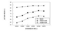
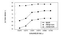
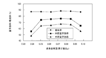
[Ca含有量に対する量子効率の評価]
カルシウム(Ca)の含有量(α/(α+β))が、0%、10%および20%の赤色蛍光体(m=3.6、x=0.135、γ=0)について、炭素(C)の含有量(y)を変化させたときの量子効率を、日本分光社製分光蛍光光度計FP−6500を用いて測定した。蛍光体の量子効率は、専用セルに蛍光体粉末を充填し、波長450nmの青色励起光を照射させて、蛍光スペクトルを測定した。その結果を、分光蛍光光度計付属の量子効率測定ソフトを用いて、赤色の量子効率を算出した。
[Evaluation of quantum efficiency with respect to Ca content]
For red phosphors (m = 3.6, x = 0.135, γ = 0) having a calcium (Ca) content (α / (α + β)) of 0%, 10% and 20%, carbon (C ) Was measured using a spectrofluorimeter FP-6500 manufactured by JASCO Corporation. Quantum efficiency of the phosphor was measured by filling a dedicated cell with phosphor powder and irradiating it with blue excitation light having a wavelength of 450 nm. The red quantum efficiency was calculated from the result using the quantum efficiency measurement software attached to the spectrofluorometer.
なお、蛍光体の効率は、励起光を吸収する効率(吸収率)、吸収した励起光を蛍光に変換する効率(内部量子効率)、及びそれらの積である励起光を蛍光に変換する効率(外部量子効率)の三種で表されるが、外部量子効率が重要である。 In addition, the efficiency of the phosphor is the efficiency of absorbing the excitation light (absorption rate), the efficiency of converting the absorbed excitation light into fluorescence (internal quantum efficiency), and the efficiency of converting the product of the excitation light into fluorescence ( The external quantum efficiency is important.
図5に、カルシウム(Ca)の含有量(α/(α+β))が10%の赤色蛍光体(m=3.6、x=0.135、α/(α+β)=0.1、γ=0)について炭素(C)の含有量(y)を変化させたときの励起光に対する吸収率、内部量子効率および外部量子効率を示す。また、図6に、カルシウム(Ca)の含有量(原子数比α/(α+β))が20%の赤色蛍光体(m=3.6、x=0.135、α/(α+β)=0.2、γ=0)について炭素(C)の含有量(y)を変化させたときの励起光に対する吸収率、内部量子効率および外部量子効率を示す。また、図7に、カルシウム(Ca)の含有量(α/(α+β))が0%の赤色蛍光体(m=3.6、x=0.135、α/(α+β)=0、γ=0)について炭素(C)の含有量(y)を変化させたときの励起光に対する吸収率、内部量子効率および外部量子効率を示す。 FIG. 5 shows a red phosphor having a calcium (Ca) content (α / (α + β)) of 10% (m = 3.6, x = 0.135, α / (α + β) = 0.1, γ = For 0), the absorptance, internal quantum efficiency, and external quantum efficiency with respect to excitation light when the content (y) of carbon (C) is changed are shown. FIG. 6 shows a red phosphor (m = 3.6, x = 0.135, α / (α + β) = 0 with a calcium (Ca) content (atomic ratio α / (α + β)) of 20%. .2, γ = 0) shows the absorptance, internal quantum efficiency, and external quantum efficiency with respect to excitation light when the carbon (C) content (y) is changed. FIG. 7 shows a red phosphor (m = 3.6, x = 0.135, α / (α + β) = 0, γ = content of calcium (Ca) (α / (α + β)) of 0%. For 0), the absorptance, internal quantum efficiency, and external quantum efficiency with respect to excitation light when the content (y) of carbon (C) is changed are shown.
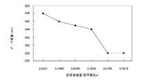
なお、実施例における炭素(C)の原子数比yは、各赤色蛍光体の作製時におけるメラミンの添加量Rを回帰直線に当てはめて求めた値である。回帰直線は、図8に示すように、赤色蛍光体の炭素(C)含有量(y)をICP発光分析装置および酸素気流中燃焼−NDIR検出方式(装置:EMIA−U511(堀場製作所製))にて分析した結果と、作製時のメラミンの添加量Rとから作成した。 In addition, the atomic ratio y of carbon (C) in the examples is a value obtained by applying the addition amount R of melamine at the time of producing each red phosphor to a regression line. As shown in FIG. 8, the regression line shows the carbon (C) content (y) of the red phosphor based on the ICP emission analyzer and the combustion in oxygen stream-NDIR detection system (apparatus: EMIA-U511 (manufactured by Horiba)). And the addition amount R of melamine at the time of preparation.
図5〜図7に示す結果から、元素Aにカルシウム(Ca)を含有する赤色蛍光体は、元素Aにカルシウム(Ca)を含有しない赤色蛍光体よりも高い外部量子効率が得られることが分かった。 From the results shown in FIGS. 5 to 7, it is understood that the red phosphor containing calcium (Ca) in the element A can obtain higher external quantum efficiency than the red phosphor not containing calcium (Ca) in the element A. It was.
また、図5および図6に示すように、元素Aにカルシウム(Ca)を含有する赤色蛍光体は、カルシウム(Ca)の含有量(α/(α+β))が10%、20%と大きくなるに従い、炭素(C)の含有量(y)を増加させることにより、外部量子効率が65%を超える結果を得ることができることが分かった。これは、カルシウム(Ca)の含有量(α/(α+β))の増加に伴い、良好な発光効率を得るために蛍光体に含有すべき炭素(C)の含有量が増加したためだと思われる。 As shown in FIGS. 5 and 6, the red phosphor containing calcium (Ca) in the element A has a large calcium (Ca) content (α / (α + β)) of 10% and 20%. Accordingly, it was found that by increasing the content (y) of carbon (C), a result that the external quantum efficiency exceeds 65% can be obtained. This seems to be due to an increase in the content of carbon (C) that should be contained in the phosphor in order to obtain good luminous efficiency with an increase in the content of calcium (Ca) (α / (α + β)). .
一方、図7示す元素Aにカルシウム(Ca)を含有しない赤色蛍光体(α/(α+β)=0)は、炭素(C)の含有量(y)を増加させても、外部量子効率が65%を超える結果は得られなかった。これは、良好な発光効率を得るために蛍光体に含有すべき炭素(C)の含有量が変化せずに、酸素(O)が取り除かれたためだと思われる。 On the other hand, the red phosphor not containing calcium (Ca) in the element A shown in FIG. 7 (α / (α + β) = 0) has an external quantum efficiency of 65 even if the content (y) of carbon (C) is increased. % Results were not obtained. This seems to be because oxygen (O) was removed without changing the carbon (C) content that should be contained in the phosphor in order to obtain good luminous efficiency.
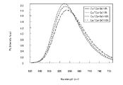
[Ca含有量に対する発光量積分値、ピーク波長、および発光スペクトルの評価]
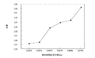
次に、カルシウム(Ca)の含有量が異なる赤色蛍光体(m=3.6、x=0.135、γ=0)の発光量積分値、ピーク波長、および発光スペクトルについて、分光光度計(SPEX社製FLUOROLOG3)を用い、450nmの励起光を照射して測定した。
[Evaluation of luminescence integrated value, peak wavelength, and emission spectrum with respect to Ca content]
Next, a spectrophotometer (emission amount integrated value, peak wavelength, and emission spectrum of red phosphors (m = 3.6, x = 0.135, γ = 0) having different calcium (Ca) contents were measured. Measurement was performed by irradiating 450 nm excitation light using SPEX FLUOROLOG3).
図9に、メラミン量(y=0.0739)を固定し、カルシウム(Ca)の含有量(α
/(α+β))を0%、5%、7.5%、10%、12.5%、15%と変化させたとき
の赤色蛍光体の発光量積分値、およびピーク波長を示す。また、図10に、これら赤色蛍
光体の発光スペクトルを示す。
In FIG. 9, the amount of melamine (y = 0.0739) is fixed, and the content of calcium (Ca) (α
/ (Α + β)) shows the integrated value of the emission amount of the red phosphor and the peak wavelength when the value is changed to 0%, 5%, 7.5%, 10%, 12.5%, and 15%. FIG. 10 shows emission spectra of these red phosphors.
また、図11に、カルシウム(Ca)の含有量(α/(α+β))が0%(y=0.0739)、10%(y=0.0766)、20%(y=0.0682)のときの赤色蛍光体の発光量積分値、およびピーク波長を示す。また、図12に、これら赤色蛍光体の発光スペクトルを示す。 FIG. 11 shows that the content of calcium (Ca) (α / (α + β)) is 0% (y = 0.0739), 10% (y = 0.0766), 20% (y = 0.0682). The emission amount integrated value of the red phosphor and the peak wavelength are shown. FIG. 12 shows emission spectra of these red phosphors.
図9および図10に示すように、メラミン量(y=0.0739)を固定してカルシウム(Ca)の含有量(α/(α+β))の値を増加させると、発光量積分値が低下する傾向となった。しかし、図11、12に示すように、カルシウム(Ca)の含有量(α/(α+β))の増加に伴い、メラミン量を増加させると(y=0.0739→y=0.0785)、発光量積分値が高くなることが分かった。 As shown in FIGS. 9 and 10, when the melamine amount (y = 0.0739) is fixed and the calcium (Ca) content (α / (α + β)) is increased, the integrated amount of luminescence decreases. It became a tendency to. However, as shown in FIGS. 11 and 12, when the amount of melamine is increased with the increase in the content of calcium (Ca) (α / (α + β)) (y = 0.0739 → y = 0.0785), It was found that the integrated value of light emission was high.
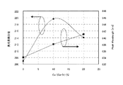
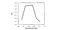
[C含有量(y)に対するピーク波長、および輝度の評価]
次に、カルシウム(Ca)の含有量(α/(α+β))が、0%、10%および20%の赤色蛍光体(m=3.6、x=0.135、γ=0)について、メラミン量を変化させたときのピーク波長、および輝度について、分光光度計(SPEX社製FLUOROLOG3)を用い、450nmの励起光を照射して測定した。
[Evaluation of peak wavelength with respect to C content (y) and luminance]
Next, for red phosphors (m = 3.6, x = 0.135, γ = 0) having a calcium (Ca) content (α / (α + β)) of 0%, 10% and 20%, The peak wavelength and luminance when the amount of melamine was changed were measured by irradiating 450 nm excitation light using a spectrophotometer (SPLU FLUOROLOG3).
図13に、カルシウム(Ca)の含有量(α/(α+β))が10%の赤色蛍光体についてメラミン量を変化させたときのピーク波長を示し、図14に、その輝度を示す。また、図15に、カルシウム(Ca)の含有量(α/(α+β))が20%の赤色蛍光体についてメラミン量を変化させたときのピーク波長を示し、図16に、その輝度を示す。また、図17に、カルシウム(Ca)の含有量(α/(α+β))が0%の赤色蛍光体についてメラミン量を変化させたときのピーク波長を示し、図18に、その輝度を示す。 FIG. 13 shows the peak wavelength when the amount of melamine is changed for a red phosphor having a calcium (Ca) content (α / (α + β)) of 10%, and FIG. 14 shows the luminance. FIG. 15 shows the peak wavelength when the amount of melamine is changed for a red phosphor having a calcium (Ca) content (α / (α + β)) of 20%, and FIG. 16 shows the luminance. FIG. 17 shows the peak wavelength when the amount of melamine is changed for a red phosphor having a calcium (Ca) content (α / (α + β)) of 0%, and FIG. 18 shows the luminance.
図13、図15および図17から分かるように、カルシウム(Ca)の含有量(α/(
α+β))が増加するに従って、ピーク波長が長波長側にシフトする傾向が見られた。ま
た、メラミン量に起因する炭素(C)の含有量(y)が増加するに従って、ピーク波長が
短波長側にシフトする傾向が見られた。すなわち、カルシウム(Ca)の含有量(α/(
α+β))と炭素(C)の含有量(y)により、ピーク波長を調整可能であることが分か
った。
As can be seen from FIGS. 13, 15 and 17, the content of calcium (Ca) (α / (
As α + β)) increased, the peak wavelength tended to shift to the longer wavelength side. Moreover, the tendency for a peak wavelength to shift to the short wavelength side was seen as content (y) of carbon (C) resulting from the amount of melamine increased. That is, the content of calcium (Ca) (α / (
It was found that the peak wavelength can be adjusted by the content (y) of α + β)) and carbon (C).
また、図14、図16および図18から分かるように、カルシウム(Ca)の含有量(α/(α+β))が増加するに従って、輝度が低下する傾向が見られた。また、メラミン量に起因する炭素(C)の含有量(y)が増加するに従って、輝度が高くなる傾向が見られた。 In addition, as can be seen from FIGS. 14, 16, and 18, the brightness tends to decrease as the calcium (Ca) content (α / (α + β)) increases. Moreover, the tendency for a brightness | luminance to become high was seen as content (y) of carbon (C) resulting from the amount of melamine increased.
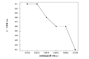
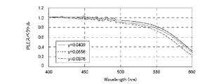
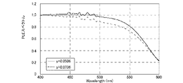
[C含有量(y)とPLEとの関係]
PLE(Photoluminescence Excitation)スペクトルは、ある特定のエネルギーのPL発光強度に着目して、その強度が励起波長を変化させたとき、どのように変わるかを示すスペクトルである。本発明者らは、良好な発光効率を得るために蛍光体に含有すべき炭素(C)の含有量が、PLEスペクトルの所定の発光特性と関係するという知見を得た。
[Relationship between C content (y) and PLE]
The PLE (Photoluminescence Excitation) spectrum is a spectrum that shows how the intensity changes when the excitation wavelength is changed by focusing on the PL emission intensity of a specific energy. The present inventors have found that the content of carbon (C) that should be contained in a phosphor in order to obtain good luminous efficiency is related to predetermined emission characteristics of the PLE spectrum.
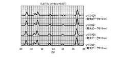
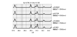
図19は、カルシウム(Ca)の含有量(α/(α+β))が10%の赤色蛍光体(m=3.6、x=0.135、γ=0)の励起波長400nmの発光強度を1としたときにおけるPLEスペクトルである。この図19では、メラミン量に起因する炭素(C)の含有量(y)が、0.0506、0.0656および0.0876の各赤色蛍光体のPLEスペクトルを示す。また、図20は、カルシウム(Ca)の含有量(α/(α+β))が20%の赤色蛍光体(m=3.6、x=0.135、γ=0)の励起波長400nmの発光強度を1としたときにおけるPLEスペクトルである。この図20では、メラミン量に起因する炭素(C)の含有量(y)が、0.0506、0.0579および0.0785の各赤色蛍光体のPLEスペクトルを示す。また、図21は、カルシウム(Ca)の含有量(α/(α+β))が0%の赤色蛍光体(m=3.6、x=0.135、γ=0)の励起波長400nmの発光強度を1としたときにおけるPLEスペクトルである。この図21では、メラミン量に起因する炭素(C)の含有量(y)が、0.0506および0.0736の各赤色蛍光体のPLEスペクトルを示す。 FIG. 19 shows the emission intensity at an excitation wavelength of 400 nm of a red phosphor (m = 3.6, x = 0.135, γ = 0) having a calcium (Ca) content (α / (α + β)) of 10%. It is a PLE spectrum when 1. In FIG. 19, the PLE spectrum of each red phosphor having carbon (C) content (y) of 0.0506, 0.0656, and 0.0876 due to the amount of melamine is shown. FIG. 20 shows light emission at an excitation wavelength of 400 nm of a red phosphor (m = 3.6, x = 0.135, γ = 0) having a calcium (Ca) content (α / (α + β)) of 20%. It is a PLE spectrum when the intensity is 1. In FIG. 20, the PLE spectrum of each red phosphor having carbon (C) content (y) of 0.0506, 0.0579 and 0.0785 due to the amount of melamine is shown. FIG. 21 shows light emission at an excitation wavelength of 400 nm of a red phosphor (m = 3.6, x = 0.135, γ = 0) having a calcium (Ca) content (α / (α + β)) of 0%. It is a PLE spectrum when the intensity is 1. In FIG. 21, the PLE spectrum of each red phosphor having a carbon (C) content (y) of 0.0506 and 0.0736 due to the amount of melamine is shown.
図19〜図21に示すPLEスペクトルにおいて、励起波長400nmの発光強度を1としたときにおける励起波長550nmの発光強度の相対値は、メラミン量に起因する炭素(C)の含有量(y)が増加するに従って低下する傾向にある。すなわち、PLEスペクトルにおいて、励起波長400nmの発光強度を1としたときにおける励起波長550nmの発光強度の相対値が0.82以下0.70以上の範囲は、メラミン量に起因する炭素(C)の含有量(y)が0.012以上0.10以下の範囲に換算することが可能である。 In the PLE spectra shown in FIGS. 19 to 21, the relative value of the emission intensity at an excitation wavelength of 550 nm when the emission intensity at an excitation wavelength of 400 nm is 1, is the content (y) of carbon (C) resulting from the amount of melamine. It tends to decrease as it increases. That is, in the PLE spectrum, the relative value of the emission intensity at an excitation wavelength of 550 nm when the emission intensity at an excitation wavelength of 400 nm is 1 is in the range of 0.82 or less and 0.70 or more. The content (y) can be converted to a range of 0.012 or more and 0.10 or less.
つまり、PLEスペクトルにおいて、励起波長400nmの発光強度を1としたときにおける励起波長550nmの発光強度の相対値が0.82以下、好ましくは0.82以下0.70以上の範囲であることにより、高い発光量積分値を得ることができることが分かった。 That is, in the PLE spectrum, when the emission intensity at an excitation wavelength of 400 nm is 1, the relative value of the emission intensity at an excitation wavelength of 550 nm is 0.82 or less, preferably 0.82 or less and 0.70 or more, It was found that a high light emission integrated value can be obtained.
[赤色蛍光体の構造]
図22および図23には、組成式(1)で表される各赤色蛍光体(α=0)をXDR分析した結果を示す。これらの図に示すように炭素(C)の含有量(原子数比y)によって、各回折角(2θ)に現れるピーク位置がシフトすることが分かる。例えば、回折角2θ=35.3付近のピークは、炭素(C)の含有量(原子数比y)の増加にともなって、回折角(2θ)が小さくなる方向にシフトした後、回折角(2θ)が大きくなる方向にシフトする。
[Structure of red phosphor]
22 and 23 show the results of XDR analysis of each red phosphor (α = 0) represented by the composition formula (1). As can be seen from these figures, the peak position appearing at each diffraction angle (2θ) shifts depending on the carbon (C) content (atomic ratio y). For example, the peak near the diffraction angle 2θ = 35.3 shifts in a direction in which the diffraction angle (2θ) decreases as the carbon (C) content (atomic ratio y) increases, and then the diffraction angle ( 2θ) shifts in the direction of increasing.
図22および23の結果から、組成式(1)で表される各赤色蛍光体は、斜方晶系空間点群Pmn21におけるa軸およびc軸が炭素(C)の含有量(原子数比y)によって伸び縮みし、これにより格子体積が膨張及び収縮することが確認された。なお、b軸はほとんど変化していない。 From the results of FIGS. 22 and 23, each red phosphor represented by the composition formula (1) has a content of carbon (C) in the a-axis and c-axis in the orthorhombic space point group Pmn21 (atomic ratio y). It was confirmed that the lattice volume expanded and contracted. Note that the b-axis has hardly changed.
これにより、赤色蛍光体内に存在する炭素(C)が、上述した単結晶内の一部を構成するようにシリコン(Si)と置き換わったため、単結晶における格子間隔が変化していることが分かる。つまり、上述した単結晶からなる赤色蛍光体内には、単結晶の一部を構成するように炭素(C)が存在していることが確認された。また、作製した赤色蛍光体は、リートベルト解析でたてた斜方晶系空間点群Pmn21のモデルと良好な一致を示した。 Thus, it can be seen that the carbon (C) existing in the red phosphor is replaced with silicon (Si) so as to constitute a part of the single crystal described above, so that the lattice spacing in the single crystal is changed. That is, it was confirmed that carbon (C) was present in the red phosphor composed of the single crystal described above so as to constitute a part of the single crystal. The produced red phosphor showed good agreement with the orthorhombic space point group Pmn21 model established by Rietveld analysis.
なお、これらの結果は、組成式(1)において、カルシウム(Ca)を含有しない赤色蛍光体(α=0)であるが、カルシウム(Ca)を含有する赤色蛍光体(α>0)についても同様な結果が得られる。 In addition, although these results are the red phosphors (α = 0) not containing calcium (Ca) in the composition formula (1), the red phosphors (α> 0) containing calcium (Ca) are also obtained. Similar results are obtained.
1 白色光源、 5 照明装置、 21 青色発光ダイオード、 43 混練物、 100 液晶表示装置、 110 液晶表示パネル、 120 バックライト(照明装置5)
DESCRIPTION OF
Claims (10)
前記混合物の焼成と、当該焼成によって得られた焼成物の粉砕とを行う赤色蛍光体の製造方法。
A method for producing a red phosphor, comprising firing the mixture and crushing the fired product obtained by the firing.
前記青色発光ダイオード上に配置されていて赤色蛍光体と緑色蛍光体とを透明樹脂に混練した混練物とを有し、
前記赤色蛍光体は、
元素A、ユーロピウム(Eu)、シリコン(Si)、炭素(C)、酸素(O)、および窒素(N)を、下記組成式(1)の原子数比で含有する白色光源。
A kneaded material disposed on the blue light emitting diode and kneaded with a red phosphor and a green phosphor in a transparent resin;
The red phosphor is
A white light source containing element A, europium (Eu), silicon (Si), carbon (C), oxygen (O), and nitrogen (N) in an atomic ratio of the following composition formula (1).
前記白色光源は、
素子基板上に形成された青色発光ダイオードと、
前記青色発光ダイオード上に配置されていて赤色蛍光体と緑色蛍光体を透明樹脂に混練した混練物を有し、
前記赤色蛍光体は、
元素A、ユーロピウム(Eu)、シリコン(Si)、炭素(C)、酸素(O)、および窒素(N)を、下記組成式(1)の原子数比で含有する照明装置。
The white light source is
A blue light emitting diode formed on the element substrate;
It has a kneaded material arranged on the blue light emitting diode and kneaded a red phosphor and a green phosphor in a transparent resin,
The red phosphor is
A lighting device containing the element A, europium (Eu), silicon (Si), carbon (C), oxygen (O), and nitrogen (N) in an atomic ratio of the following composition formula (1).
前記液晶表示パネルを照明する複数の白色光源を用いたバックライトとを有し、
前記白色光源は、
素子基板上に形成された青色発光ダイオードと、
前記青色発光ダイオード上に配置されていて赤色蛍光体と緑色蛍光体を透明樹脂に混練した混練物を有し、
前記赤色蛍光体は、
元素A、ユーロピウム(Eu)、シリコン(Si)、炭素(C)、酸素(O)、および窒素(N)を、下記組成式(1)の原子数比で含有する液晶表示装置。
A backlight using a plurality of white light sources for illuminating the liquid crystal display panel;
The white light source is
A blue light emitting diode formed on the element substrate;
It has a kneaded material arranged on the blue light emitting diode and kneaded a red phosphor and a green phosphor in a transparent resin,
The red phosphor is
A liquid crystal display device containing the element A, europium (Eu), silicon (Si), carbon (C), oxygen (O), and nitrogen (N) in an atomic ratio of the following composition formula (1).
Priority Applications (8)
| Application Number | Priority Date | Filing Date | Title |
|---|---|---|---|
| JP2011108873A JP5695968B2 (en) | 2010-12-28 | 2011-05-14 | Red phosphor, method for producing red phosphor, white light source, illumination device, and liquid crystal display device |
| US13/814,671 US8961827B2 (en) | 2010-12-28 | 2011-12-28 | Red fluorescent material, method for producing red fluorescent material, white light source, illuminating device, and liquid crystal display |
| CN201180029818.0A CN103097489B (en) | 2010-12-28 | 2011-12-28 | The preparation method of red-emitting phosphors, red-emitting phosphors, white light source, means of illumination and liquid crystal indicator |
| KR1020127031047A KR101875972B1 (en) | 2010-12-28 | 2011-12-28 | Red phosphor, production method for red phosphor, white light source, illumination device, and liquid crystal display device |
| EP11854196.0A EP2660301B1 (en) | 2010-12-28 | 2011-12-28 | Red phosphor, production method for red phosphor, white light source, illumination device, and liquid crystal display device |
| US13/338,592 US8808578B2 (en) | 2010-12-28 | 2011-12-28 | Red phosphor, method for producing red phosphor, white light source, illuminating device, and liquid crystal display device |
| PCT/JP2011/080507 WO2012091134A1 (en) | 2010-12-28 | 2011-12-28 | Red phosphor, production method for red phosphor, white light source, illumination device, and liquid crystal display device |
| US14/329,793 US9493701B2 (en) | 2010-12-28 | 2014-07-11 | Red phosphor, method for producing red phosphor, white light source, illuminating device, and liquid crystal display device |
Applications Claiming Priority (3)
| Application Number | Priority Date | Filing Date | Title |
|---|---|---|---|
| JP2010293419 | 2010-12-28 | ||
| JP2010293419 | 2010-12-28 | ||
| JP2011108873A JP5695968B2 (en) | 2010-12-28 | 2011-05-14 | Red phosphor, method for producing red phosphor, white light source, illumination device, and liquid crystal display device |
Publications (2)
| Publication Number | Publication Date |
|---|---|
| JP2012149209A true JP2012149209A (en) | 2012-08-09 |
| JP5695968B2 JP5695968B2 (en) | 2015-04-08 |
Family
ID=46383221
Family Applications (1)
| Application Number | Title | Priority Date | Filing Date |
|---|---|---|---|
| JP2011108873A Active JP5695968B2 (en) | 2010-12-28 | 2011-05-14 | Red phosphor, method for producing red phosphor, white light source, illumination device, and liquid crystal display device |
Country Status (6)
| Country | Link |
|---|---|
| US (1) | US8961827B2 (en) |
| EP (1) | EP2660301B1 (en) |
| JP (1) | JP5695968B2 (en) |
| KR (1) | KR101875972B1 (en) |
| CN (1) | CN103097489B (en) |
| WO (1) | WO2012091134A1 (en) |
Cited By (1)
| Publication number | Priority date | Publication date | Assignee | Title |
|---|---|---|---|---|
| JP2016156022A (en) * | 2011-01-04 | 2016-09-01 | デクセリアルズ株式会社 | Red phosphor, production method of red phosphor, white light source, illuminating device, and liquid crystal display device |
Families Citing this family (4)
| Publication number | Priority date | Publication date | Assignee | Title |
|---|---|---|---|---|
| JP2012153873A (en) * | 2011-01-04 | 2012-08-16 | Sony Chemical & Information Device Corp | Red phosphor, method for producing red phosphor, white light source, illuminating device, and liquid crystal display device |
| JP6034557B2 (en) * | 2011-05-14 | 2016-11-30 | デクセリアルズ株式会社 | Method for producing red phosphor |
| JP2017088800A (en) | 2015-11-16 | 2017-05-25 | サムスン エレクトロニクス カンパニー リミテッド | Fluophor and manufacturing method therefor |
| CN107324785A (en) * | 2017-08-08 | 2017-11-07 | 长兴俊泽炉窑工程有限公司 | A kind of steel-smelting electric furnace special-purpose fire-resistant brick |
Citations (4)
| Publication number | Priority date | Publication date | Assignee | Title |
|---|---|---|---|---|
| WO2006106883A1 (en) * | 2005-03-31 | 2006-10-12 | Dowa Electronics Materials Co., Ltd. | Fluorescent substance, fluorescent substance sheet and process for producing the same, and luminescent device using said fluorescent substance |
| JP2008120946A (en) * | 2006-11-14 | 2008-05-29 | Sony Corp | Manufacturing method of luminescent composition, manufacturing method of light source device and manufacturing method of display |
| WO2009050171A2 (en) * | 2007-10-15 | 2009-04-23 | Leuchtstoffwerk Breitungen Gmbh | Rare-earth doped alkaline-earth silicon nitride phosphor, method for producing and radiation converting device comprising such a phosphor |
| JP2011001530A (en) * | 2008-07-02 | 2011-01-06 | Sony Corp | Red phosphor, method for producing red phosphor, white light source, illuminating device, and liquid crystal display |
Family Cites Families (9)
| Publication number | Priority date | Publication date | Assignee | Title |
|---|---|---|---|---|
| US6686691B1 (en) | 1999-09-27 | 2004-02-03 | Lumileds Lighting, U.S., Llc | Tri-color, white light LED lamps |
| CA2447288C (en) * | 2002-03-22 | 2011-10-04 | Nichia Corporation | Nitride phosphor and method for preparation thereof, and light emitting device |
| US7488432B2 (en) * | 2003-10-28 | 2009-02-10 | Nichia Corporation | Fluorescent material and light-emitting device |
| JP3931239B2 (en) | 2004-02-18 | 2007-06-13 | 独立行政法人物質・材料研究機構 | Light emitting device and lighting apparatus |
| JP2006257385A (en) * | 2004-09-09 | 2006-09-28 | Showa Denko Kk | Oxynitride phosphor and method for producing the same |
| DE112005002277T5 (en) * | 2004-09-29 | 2009-05-07 | Showa Denko K.K. | Oxynitride based fluorescent material and method of making the same |
| ATE509082T1 (en) * | 2007-10-15 | 2011-05-15 | Leuchtstoffwerk Breitungen | METHOD FOR PRODUCING A RARE EARTH-DOPED ALKALINE EARTH SILICON NITRIDE LAMP, A RARE EARTH-DOPED ALKALINE SILICON NITRIDE LAMP THAT CAN BE PRODUCED IN THIS WAY AND RADIATION EMITTING DEVICE HAVING SUCH A RARE EARTH-DOPED ALKALINE SILICON NITRIDE LIGHT TSTABIL |
| JP2012000946A (en) * | 2010-06-21 | 2012-01-05 | Toppan Printing Co Ltd | Printing surface plate and base material for back surface, and method for forming pattern on film substrate |
| CN101864300B (en) * | 2010-06-30 | 2013-08-14 | 彩虹集团公司 | Rare-earth doped nitrogen oxide fluorescent powder and preparation method thereof |
-
2011
- 2011-05-14 JP JP2011108873A patent/JP5695968B2/en active Active
- 2011-12-28 EP EP11854196.0A patent/EP2660301B1/en active Active
- 2011-12-28 WO PCT/JP2011/080507 patent/WO2012091134A1/en active Application Filing
- 2011-12-28 KR KR1020127031047A patent/KR101875972B1/en active IP Right Grant
- 2011-12-28 CN CN201180029818.0A patent/CN103097489B/en active Active
- 2011-12-28 US US13/814,671 patent/US8961827B2/en active Active
Patent Citations (4)
| Publication number | Priority date | Publication date | Assignee | Title |
|---|---|---|---|---|
| WO2006106883A1 (en) * | 2005-03-31 | 2006-10-12 | Dowa Electronics Materials Co., Ltd. | Fluorescent substance, fluorescent substance sheet and process for producing the same, and luminescent device using said fluorescent substance |
| JP2008120946A (en) * | 2006-11-14 | 2008-05-29 | Sony Corp | Manufacturing method of luminescent composition, manufacturing method of light source device and manufacturing method of display |
| WO2009050171A2 (en) * | 2007-10-15 | 2009-04-23 | Leuchtstoffwerk Breitungen Gmbh | Rare-earth doped alkaline-earth silicon nitride phosphor, method for producing and radiation converting device comprising such a phosphor |
| JP2011001530A (en) * | 2008-07-02 | 2011-01-06 | Sony Corp | Red phosphor, method for producing red phosphor, white light source, illuminating device, and liquid crystal display |
Cited By (1)
| Publication number | Priority date | Publication date | Assignee | Title |
|---|---|---|---|---|
| JP2016156022A (en) * | 2011-01-04 | 2016-09-01 | デクセリアルズ株式会社 | Red phosphor, production method of red phosphor, white light source, illuminating device, and liquid crystal display device |
Also Published As
| Publication number | Publication date |
|---|---|
| CN103097489B (en) | 2016-01-27 |
| US20130154470A1 (en) | 2013-06-20 |
| JP5695968B2 (en) | 2015-04-08 |
| EP2660301A1 (en) | 2013-11-06 |
| EP2660301B1 (en) | 2016-03-30 |
| EP2660301A4 (en) | 2014-07-02 |
| KR101875972B1 (en) | 2018-07-06 |
| US8961827B2 (en) | 2015-02-24 |
| KR20130114571A (en) | 2013-10-17 |
| WO2012091134A1 (en) | 2012-07-05 |
| CN103097489A (en) | 2013-05-08 |
Similar Documents
| Publication | Publication Date | Title |
|---|---|---|
| JP4978819B2 (en) | Red phosphor, method for producing red phosphor, white light source, illumination device, and liquid crystal display device | |
| WO2012093644A1 (en) | Red phosphor, method for producing red phosphor, white light source, illumination device, and liquid crystal display device | |
| JP5695968B2 (en) | Red phosphor, method for producing red phosphor, white light source, illumination device, and liquid crystal display device | |
| US9493701B2 (en) | Red phosphor, method for producing red phosphor, white light source, illuminating device, and liquid crystal display device | |
| JP6034557B2 (en) | Method for producing red phosphor | |
| US20190249080A1 (en) | Red fluorescent substance, method for producing red fluorescent substance, white light source, lighting device, and liquid crystal display device | |
| JP6084320B2 (en) | Red phosphor, method for producing red phosphor, white light source, illumination device, and liquid crystal display device | |
| JP5753438B2 (en) | Red phosphor, method for producing red phosphor, white light source, illumination device, and liquid crystal display device | |
| JP2012241025A (en) | Red phosphor, method for producing red phosphor, white light source, illuminating device, and liquid crystal display device | |
| JP2012241027A (en) | Red phosphor, method for producing red phosphor, white light source, illuminating device, and liquid crystal display device | |
| JP2016028158A (en) | Red phosphor, production method of red phosphor, white light source, lighting device, and liquid crystal display device | |
| JP2012241026A (en) | Red phosphor, method for producing red phosphor, white light source, illuminating device, and liquid crystal display device |
Legal Events
| Date | Code | Title | Description |
|---|---|---|---|
| A711 | Notification of change in applicant |
Free format text: JAPANESE INTERMEDIATE CODE: A711 Effective date: 20120518 |
|
| A621 | Written request for application examination |
Free format text: JAPANESE INTERMEDIATE CODE: A621 Effective date: 20140418 |
|
| A131 | Notification of reasons for refusal |
Free format text: JAPANESE INTERMEDIATE CODE: A131 Effective date: 20141007 |
|
| A521 | Request for written amendment filed |
Free format text: JAPANESE INTERMEDIATE CODE: A523 Effective date: 20141208 |
|
| TRDD | Decision of grant or rejection written | ||
| A01 | Written decision to grant a patent or to grant a registration (utility model) |
Free format text: JAPANESE INTERMEDIATE CODE: A01 Effective date: 20150113 |
|
| A61 | First payment of annual fees (during grant procedure) |
Free format text: JAPANESE INTERMEDIATE CODE: A61 Effective date: 20150209 |
|
| R150 | Certificate of patent or registration of utility model |
Ref document number: 5695968 Country of ref document: JP Free format text: JAPANESE INTERMEDIATE CODE: R150 |
|
| R250 | Receipt of annual fees |
Free format text: JAPANESE INTERMEDIATE CODE: R250 |
|
| R250 | Receipt of annual fees |
Free format text: JAPANESE INTERMEDIATE CODE: R250 |
|
| R250 | Receipt of annual fees |
Free format text: JAPANESE INTERMEDIATE CODE: R250 |
|
| R250 | Receipt of annual fees |
Free format text: JAPANESE INTERMEDIATE CODE: R250 |
|
| R250 | Receipt of annual fees |
Free format text: JAPANESE INTERMEDIATE CODE: R250 |
|
| R250 | Receipt of annual fees |
Free format text: JAPANESE INTERMEDIATE CODE: R250 |
|
| R250 | Receipt of annual fees |
Free format text: JAPANESE INTERMEDIATE CODE: R250 |