JP2012148734A - Suspension device - Google Patents

Suspension device Download PDF

Info

Publication number
JP2012148734A
JP2012148734A JP2011010643A JP2011010643A JP2012148734A JP 2012148734 A JP2012148734 A JP 2012148734A JP 2011010643 A JP2011010643 A JP 2011010643A JP 2011010643 A JP2011010643 A JP 2011010643A JP 2012148734 A JP2012148734 A JP 2012148734A
Authority
JP
Japan
Prior art keywords
damping force
shock absorber
speed
expansion
target
Prior art date
Legal status (The legal status is an assumption and is not a legal conclusion. Google has not performed a legal analysis and makes no representation as to the accuracy of the status listed.)
Granted
Application number
JP2011010643A
Other languages
Japanese (ja)
Other versions
JP5603787B2 (en
Inventor
Tomoo Kubota
友夫 窪田
Current Assignee (The listed assignees may be inaccurate. Google has not performed a legal analysis and makes no representation or warranty as to the accuracy of the list.)
KYB Corp
Original Assignee
KYB Corp
Priority date (The priority date is an assumption and is not a legal conclusion. Google has not performed a legal analysis and makes no representation as to the accuracy of the date listed.)
Filing date
Publication date
Application filed by KYB Corp filed Critical KYB Corp
Priority to JP2011010643A priority Critical patent/JP5603787B2/en
Publication of JP2012148734A publication Critical patent/JP2012148734A/en
Application granted granted Critical
Publication of JP5603787B2 publication Critical patent/JP5603787B2/en
Active legal-status Critical Current
Anticipated expiration legal-status Critical

Links

Images

Abstract

PROBLEM TO BE SOLVED: To provide a suspension device improving ride quality of a vehicle by alleviating a sudden change of a generated damping force of a shock absorber.SOLUTION: The suspension device 1 includes the shock absorber 2 interposed between a vehicle body and wheels of the vehicle and exerting the damping force controlling relative movement of the vehicle body and the wheels in a vertical direction, a damping force adjusting mechanism 3 adjusting the damping force, and a control device 4 controlling the damping force adjusting mechanism 3 based on a target damping force. The control device 4 includes a correcting means 43 correcting the target damping force so that the change of the generated damping force of the shock absorber may be alleviated when the expansion/contraction speed of the shock absorber 2 is zero and a predetermined value. The correction means 43 corrects the generated damping force by offset toward speed increase by the difference β between a speed threshold value Vand a predetermined speed Vuntil the expansion/contraction speed x of the shock absorber 2 reaches zero when the expansion/contraction speed x exceeds the speed threshold value V, and when the difference is from β to zero, correction is made to minimize the generated damping force.

Description

本発明は、サスペンション装置に関する。   The present invention relates to a suspension device.

従来、サスペンション装置にあっては、たとえば、車両における車体と車輪との間に介装されて車体と車輪との上下方向の相対移動を抑制する減衰力を発揮する緩衝器と、供給される電流量に応じて当該緩衝器における減衰力を調節する減衰力調整機構と、当該減衰力調整機構を制御する制御装置とを備えているものがある(たとえば、特許文献1参照)。   Conventionally, in a suspension device, for example, a shock absorber that is interposed between a vehicle body and a wheel in a vehicle and exhibits a damping force that suppresses relative movement in the vertical direction between the vehicle body and the wheel, and a supplied current Some include a damping force adjustment mechanism that adjusts the damping force in the shock absorber according to the amount and a control device that controls the damping force adjustment mechanism (see, for example, Patent Document 1).

このサスペンション装置における緩衝器は、図16に示すように、緩衝器の伸縮速度が極低速域にある場合を除き、減衰力調整機構へ供給する電流量を変化させても減衰特性(緩衝器の伸縮速度に対する減衰力の特性)の傾きが変わらない性質を持っており、予め緩衝器の最低減衰力を把握しておき、緩衝器に発生させたい減衰力からその時の緩衝器の伸縮速度における最低減衰力を減算して目標減衰力とすれば、伸縮速度によらず、目標減衰力から減衰力調整機構へ供給すべき電流量を求めることができるようになっている。   As shown in FIG. 16, the shock absorber in this suspension device has a damping characteristic (the shock absorber's shock absorber) even if the amount of current supplied to the damping force adjusting mechanism is changed, except when the expansion / contraction speed of the shock absorber is in an extremely low speed range. It has the property that the slope of the damping force with respect to the expansion / contraction speed does not change, knows the minimum damping force of the shock absorber in advance, and determines the minimum at the expansion / contraction speed of the shock absorber at that time from the damping force to be generated by the shock absorber. If the damping force is subtracted to obtain the target damping force, the amount of current to be supplied from the target damping force to the damping force adjusting mechanism can be obtained regardless of the expansion / contraction speed.

しかしながら、特開2008−12959号公報に開示されているサスペンション装置では、緩衝器の伸縮速度が極低速域にある場合、目標減衰力通りには減衰力が発揮されず、また、緩衝器は伸縮方向と同一方向へは減衰力を発生させることができないため、目標減衰力が0ではなく、緩衝器の伸縮方向が切換って緩衝器が減衰力を発生できる状態となる場合、図16の原点Oで減衰特性の傾きが大きく変化していることから、緩衝器の発生減衰力の変化が急峻となってしまう。   However, in the suspension device disclosed in Japanese Patent Application Laid-Open No. 2008-12959, when the expansion / contraction speed of the shock absorber is in an extremely low speed region, the damping force is not exhibited according to the target damping force, and the shock absorber expands / contracts. Since the damping force cannot be generated in the same direction as the direction, the target damping force is not 0, and the shock absorber can generate a damping force by switching the expansion / contraction direction of the shock absorber. Since the slope of the damping characteristic is greatly changed by O, the change in the damping force generated by the shock absorber becomes steep.

この減衰力の急変を回避するために、電流指令から双曲線正接関数を用いて減衰力調整機構へ出力する供給電流を求めることで、発生減衰力の急峻な変化を緩和する技術が開示されている(たとえば、特許文献2参照)。   In order to avoid this sudden change in damping force, a technique for mitigating a steep change in generated damping force by obtaining a supply current to be output to the damping force adjustment mechanism from a current command using a hyperbolic tangent function is disclosed. (For example, refer to Patent Document 2).

特開2008−12959号公報JP 2008-12959 A 特開2010−52488号公報JP 2010-52488 A

特許文献2の技術では、特に、減衰力制御範囲外から減衰力制御範囲内へ電流指令が遷移する場合に減衰力の急変を緩和できる点で有効ではあるが、緩衝器の伸縮方向が切り替わり、それまで出力していた減衰力を最小にしなければならない場合には、ヒステリシスが生じて速やかに減衰力を最小にすることができずに、車両における乗り心地をかえって悪化させてしまう場合がある。   The technique of Patent Document 2 is effective in that it can alleviate a sudden change in damping force when a current command transitions from outside the damping force control range to within the damping force control range, but the expansion / contraction direction of the shock absorber is switched, When the damping force that has been output until then has to be minimized, there is a case where hysteresis occurs and the damping force cannot be minimized immediately, and the riding comfort in the vehicle may be deteriorated.

というのは、車両のばね下振動の周波数は概ね10Hz〜20Hzと高く、電流指令から供給電流を得るのにヒステリシスがないように設定していても、特許文献1の緩衝器における減衰力調整機構やそれ以外にもソレノイドバルブを減衰力調整機構に採用している場合には、減衰力調整機構の回路中に誘導性負荷があって、当該回路の時定数によって実電流を下降させるのに無駄時間が生じるため、供給電流を指令電流から求めた通りに制御することができない。たとえば、緩衝器に収縮方向の減衰力を発揮させることを条件として、緩衝器が収縮してから伸長に転じ、さらに、収縮するまでを考えると、緩衝器は自身では積極的に伸縮させる力を発揮できないので、この場合、緩衝器が収縮しているときには緩衝器の減衰力を限りなく小さくすることになる。この緩衝器が減衰力調整機構へ供給する電流を0にすると減衰力を最低とすることができるとすると、図17に示すように、緩衝器が収縮行程にあるときには、減衰力調整機構へ供給する電流を0としているので実電流は0に維持され(図中線I1)、緩衝器が伸長行程に転じると減衰力調整機構へ供給されている実電流の急変が緩和されて徐々に大きくなって目標減衰力を発揮させる電流値にまで上昇する(図中線I2)。そして、緩衝器がさらに反転して収縮行程に至ると、今度は、供給電流が徐々に減少することになるが、先程のように、無駄時間の問題があって、実電流はすぐには0にはならず、応答に遅れが生じて、図中で線I1に対して収縮側にずれてヒステリシスが生じる(図中線I3)。   This is because the frequency of the unsprung vibration of the vehicle is as high as approximately 10 Hz to 20 Hz, and the damping force adjusting mechanism in the shock absorber of Patent Document 1 is set so that there is no hysteresis for obtaining the supply current from the current command. In addition, when a solenoid valve is used for the damping force adjustment mechanism, there is an inductive load in the circuit of the damping force adjustment mechanism, and it is useless to reduce the actual current due to the time constant of the circuit. Since time is generated, the supply current cannot be controlled as determined from the command current. For example, on the condition that the shock absorber exerts a damping force in the contraction direction, considering that the shock absorber contracts and then expands and then contracts, the shock absorber itself exerts a force to actively expand and contract. In this case, when the shock absorber is contracted, the damping force of the shock absorber is reduced as much as possible. Assuming that the damping force can be minimized when the current supplied to the damping force adjusting mechanism by the shock absorber is zero, as shown in FIG. 17, when the shock absorber is in the contraction stroke, the damping force is supplied to the damping force adjusting mechanism. The actual current is maintained at 0 (line I1 in the figure), and when the shock absorber starts to extend, the sudden change in the actual current supplied to the damping force adjusting mechanism is alleviated and gradually increased. As a result, the current value increases to a current value that exhibits the target damping force (line I2 in the figure). Then, when the shock absorber further reverses and reaches the contraction stroke, the supply current gradually decreases. However, as described above, there is a problem of dead time, and the actual current immediately becomes 0. However, a delay occurs in the response, and the hysteresis shifts toward the contraction side with respect to the line I1 in the figure (line I3 in the figure).

このようにヒステリシスを生じると、緩衝器の伸縮方向の切換りに実電流が残ってしまって、緩衝器が意図しない減衰力を発揮することになり、緩衝器の伸縮速度が0の近傍で減衰力が急変してしまい、車両における乗り心地を悪化させてしまう可能性があるのである。   When hysteresis occurs in this way, the actual current remains in switching the expansion / contraction direction of the shock absorber, and the shock absorber exerts an unintended damping force. The force may change suddenly and the ride comfort of the vehicle may be deteriorated.

そこで、本発明は、上記した不具合を改善するために創案されたものであって、その目的とするところは、緩衝器の発生減衰力の急変を確実に緩和して車両における乗り心地を向上することができるサスペンション装置を提供することである。   Accordingly, the present invention has been developed to improve the above-described problems, and the object of the present invention is to reliably reduce sudden changes in the damping force generated by the shock absorber and improve the riding comfort in the vehicle. A suspension device is provided.

上記目的を達成するために、本発明の課題解決手段は、車両における車体と車輪との間に介装されて車体と車輪との上下方向の相対移動を抑制する減衰力を発揮する緩衝器と、減衰力を調節する減衰力調整機構と、目標減衰力に基づいて当該減衰力調整機構を制御する制御装置とを備えたサスペンション装置において、上記制御装置は、上記緩衝器の伸縮速度が0および所定速度における緩衝器の発生減衰力の変化を緩和する補正手段を備え、当該補正手段は、緩衝器の伸縮速度が上記所定速度を超える値に設定される速度閾値を超えると当該伸縮速度が0となるまでは、発生減衰力変化を緩和する伸縮速度を上記速度閾値と上記所定速度の差分だけ速度増側へオフセットして目標減衰力を補正するとともに差分から0までは目標減衰力を0とするよう補正することを特徴とする。   In order to achieve the above object, the problem-solving means of the present invention includes a shock absorber that is interposed between a vehicle body and a wheel in a vehicle and exhibits a damping force that suppresses relative movement in the vertical direction between the vehicle body and the wheel. The suspension device includes a damping force adjusting mechanism that adjusts the damping force and a control device that controls the damping force adjusting mechanism based on the target damping force. Compensating means for reducing the change in the damping force generated by the shock absorber at a predetermined speed is provided, and when the telescopic speed of the shock absorber exceeds a speed threshold set to a value exceeding the predetermined speed, the telescopic speed is zero. Until it becomes, the expansion / contraction speed for reducing the generated damping force change is offset to the speed increasing side by the difference between the speed threshold and the predetermined speed, and the target damping force is corrected from 0 to 0. And correcting to.

本発明のサスペンション装置によれば、緩衝器の発生減衰力の急変を確実に緩和して車両における乗り心地を向上することができる。   According to the suspension device of the present invention, it is possible to reliably relieve a sudden change in the damping force generated by the shock absorber and improve the riding comfort in the vehicle.

一実施の形態におけるサスペンション装置のシステム構成図である。1 is a system configuration diagram of a suspension device according to an embodiment. 一実施の形態におけるサスペンション装置の緩衝器の一例を示した図である。It is the figure which showed an example of the buffer of the suspension apparatus in one embodiment. 一実施の形態におけるサスペンション装置の緩衝器の伸縮速度に対する減衰力の特性(減衰特性)を示した図である。It is the figure which showed the characteristic (damping characteristic) of the damping force with respect to the expansion-contraction speed of the buffer of the suspension apparatus in one Embodiment. 目標減衰力と緩衝器の伸縮速度との関係を示す図である。It is a figure which shows the relationship between target damping force and the expansion-contraction speed of a buffer. 緩衝器の伸縮速度が速度閾値を超えない場合の補正後の目標減衰力と緩衝器の伸縮速度との関係を示す図である。It is a figure which shows the relationship between the target damping force after correction | amendment when the expansion-contraction speed of a buffer does not exceed a speed threshold value, and the expansion-contraction speed of a buffer. 目標減衰力と所定速度との相関関係を説明する図である。It is a figure explaining the correlation of target damping force and predetermined speed. 緩衝器の伸縮速度が速度閾値を超えて0となるまでの補正後の目標減衰力と緩衝器の伸縮速度との関係を示す図である。It is a figure which shows the relationship between the target damping force after correction | amendment until the expansion-contraction speed of a shock absorber exceeds a speed threshold value, and becomes the expansion-contraction speed of a shock absorber. 補正手段による補正処理を実際の緩衝器の動きに即して説明する図である。It is a figure explaining the correction process by a correction means according to the motion of an actual shock absorber. 補正手段によって補正された指令に対する減衰力調整機構に実際に流れる電流を説明する図である。It is a figure explaining the electric current which actually flows into the damping force adjustment mechanism with respect to the instruction | command corrected by the correction | amendment means. 一実施の形態におけるサスペンション装置の目標減衰力から目標電流指令値を得る演算に使用する収縮側マップを説明する図である。It is a figure explaining the shrinkage | contraction side map used for the calculation which obtains a target electric current command value from the target damping force of the suspension apparatus in one embodiment. 一実施の形態におけるサスペンション装置の目標減衰力から目標電流指令値を得る演算に使用する伸長側マップを説明する図である。It is a figure explaining the expansion | extension side map used for the calculation which obtains a target electric current command value from the target damping force of the suspension apparatus in one embodiment. 一実施の形態におけるサスペンション装置の補正後の目標減衰力の一例を示した図である。It is the figure which showed an example of the target damping force after correction | amendment of the suspension apparatus in one Embodiment. 他の実施の形態におけるサスペンション装置の目標減衰力から目標電流指令値を得る演算に使用する収縮側マップを説明する図である。It is a figure explaining the shrinkage | contraction side map used for the calculation which obtains a target electric current command value from the target damping force of the suspension apparatus in other embodiment. 他の実施の形態におけるサスペンション装置の目標減衰力から目標評電流指令値を得る演算に使用する伸長側マップを説明する図である。It is a figure explaining the expansion | extension side map used for the calculation which obtains a target evaluation current command value from the target damping force of the suspension apparatus in other embodiment. 他の実施の形態におけるサスペンション装置の目標電流指令値或いは目標電圧指令値に乗ずるゲインを説明する図である。It is a figure explaining the gain by which the target electric current command value or target voltage command value of the suspension apparatus in other embodiment is multiplied. 従来のサスペンション装置の緩衝器の伸縮速度に対する減衰力の特性(減衰特性)を示した図である。It is the figure which showed the characteristic (damping characteristic) of the damping force with respect to the expansion-contraction speed of the buffer of the conventional suspension apparatus. 従来のサスペンション装置の緩衝器における減衰力調整機構に流れる実電流と緩衝器の伸縮速度との関係を説明する図である。It is a figure explaining the relationship between the actual electric current which flows into the damping-force adjustment mechanism in the buffer of the conventional suspension apparatus, and the expansion-contraction speed of a buffer.

以下、図に示した実施の形態に基づき、本発明を説明する。図1に示すように、一実施の形態におけるサスペンション装置1は、図示しない車両における車体と車輪との間に介装されて車体と車輪との上下方向の相対移動を抑制する減衰力を発揮する緩衝器2と、供給される電流量に応じて当該緩衝器2における減衰力を調節可能な減衰力調整機構3と、当該減衰力調整機構3を制御する制御装置4とを備えて構成されている。   The present invention will be described below based on the embodiments shown in the drawings. As shown in FIG. 1, a suspension device 1 according to an embodiment is provided between a vehicle body and a wheel in a vehicle (not shown) and exhibits a damping force that suppresses relative movement in the vertical direction between the vehicle body and the wheel. The shock absorber 2 includes a damping force adjustment mechanism 3 that can adjust the damping force in the shock absorber 2 according to the amount of current supplied, and a control device 4 that controls the damping force adjustment mechanism 3. Yes.

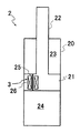
以下、各部材について詳細に説明すると、緩衝器2は、図2に示すように、シリンダ20と、シリンダ20内に摺動自在に挿入されるピストン21と、シリンダ20内に移動自在に挿入されてピストン21に連結されるピストンロッド22と、シリンダ20内にピストン21で区画されるとともに磁気粘性流体が充填される二つの圧力室23,24と、圧力室23,24同士を連通する通路25と、通路25を通過する磁気粘性流体に磁気を与えるコイル26とを備えて構成されており、車両の車体と車輪との間に介装されている。そして、この緩衝器2は、シリンダ20とピストンロッド22の軸方向の相対移動である伸縮作動に応じて圧力室23,24内に充填された磁気粘性流体が通路25を通過する際にコイル26への通電によって磁気を与えて、磁気粘性流体の移動に抵抗を与え、圧力室23,24間に差圧を生じせしめて、当該伸縮作動を抑制する減衰力を発揮し、車体と車輪の上下方向の相対移動を抑制するようになっている。なお、緩衝器2が片ロッド型緩衝器である場合、緩衝器2は、図示はしないが、シリンダ20内にピストンロッド22が出入りする体積を補償するために気体室やリザーバを備える。また、詳しくは図示しないが、緩衝器2がリザーバを備えて伸長しても収縮してもシリンダ20内からリザーバへ通じる通路を介して流体が排出されるユニフロー型に設定される場合、シリンダ20からリザーバへ通じる通路の途中にコイルを設けて、流体の流れに抵抗を与えて減衰力を発揮するようにしてもよい。   Hereinafter, each member will be described in detail. As shown in FIG. 2, the shock absorber 2 is inserted into the cylinder 20, the piston 21 slidably inserted into the cylinder 20, and the movably inserted into the cylinder 20. A piston rod 22 connected to the piston 21, two pressure chambers 23 and 24 that are partitioned by the piston 21 in the cylinder 20 and filled with a magnetorheological fluid, and a passage 25 that communicates the pressure chambers 23 and 24 with each other. And a coil 26 that gives magnetism to the magnetorheological fluid passing through the passage 25, and is interposed between the vehicle body and the wheel of the vehicle. The shock absorber 2 includes a coil 26 when the magnetorheological fluid filled in the pressure chambers 23 and 24 passes through the passage 25 in accordance with the expansion and contraction operation that is the relative movement of the cylinder 20 and the piston rod 22 in the axial direction. The magnetism is applied by energizing the motor, resistance is given to the movement of the magnetorheological fluid, a differential pressure is generated between the pressure chambers 23 and 24, and a damping force that suppresses the expansion and contraction operation is exerted. The relative movement of the direction is suppressed. When the shock absorber 2 is a single rod type shock absorber, the shock absorber 2 includes a gas chamber and a reservoir to compensate for the volume of the piston rod 22 entering and exiting the cylinder 20 (not shown). Further, although not shown in detail, when the shock absorber 2 is provided with a reservoir and is set to a uniflow type in which fluid is discharged through a passage leading from the inside of the cylinder 20 to the reservoir even when the shock absorber 2 extends or contracts, the cylinder 20 A coil may be provided in the middle of the passage leading from the reservoir to the reservoir so as to exert a damping force by imparting resistance to the fluid flow.

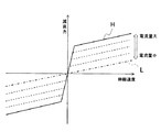
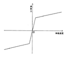
したがって、この実施の形態の場合、減衰力調整機構3は、磁気粘性流体に磁気を与えるコイル26とされていて、コイル26へ与える電流量を調節することにより、磁気粘性流体へ与える磁界の強さを調節することで、当該磁気粘性流体が通路25を通過する流れに与える抵抗の大きさを調節し、緩衝器2の発生減衰力を調節することができるようになっている。なお、この実施の形態の場合、図3に示すように、コイル26へ電流供給をしないと、磁気粘性流体に磁気が与えられず、緩衝器2の減衰特性は図中一点鎖線で示した最小の減衰特性Lとなり、コイル26への供給電流量が大きければ大きいほど、緩衝器2の発生減衰力も大きくなるようになっていて、ハードウェアとして制限される最大の電流供給量をコイル26へ与えると緩衝器2の減衰特性は図中実線で示した最大の減衰特性Hとなる。また、この実施の形態の場合、制御が容易となるように、緩衝器2の伸縮速度が極低速域にある場合を除き、コイル26へ供給する電流量に応じて、図3中破線で示すように傾きを一定に保ったまま減衰特性を最小Lから最大Hまで上下方向へ調節することができるようになっている。本実施の形態においては、減衰特性の変化を説明するために、緩衝器の伸縮速度に極低速域との区分を設けているが、極低速域は緩衝器の伸縮速度の絶対値が0から任意の速度までの範囲を示しており、当該範囲は、緩衝器2の設計に応じて任意に設定することができる。なお、図3で示したところでは、緩衝器の収縮を抑制する方向(伸長方向)の減衰力を正とし、緩衝器の伸長を抑制する方向(収縮方向)の減衰力を負とし、伸縮速度は、緩衝器の収縮方向を正とし、緩衝器の伸長方向を負として扱っている。このことは、後述する制御装置4における処理のうち補正部43での処理以外で同様である。   Therefore, in this embodiment, the damping force adjusting mechanism 3 is the coil 26 that gives magnetism to the magnetorheological fluid. By adjusting the amount of current that is given to the coil 26, the strength of the magnetic field that is given to the magnetorheological fluid is increased. By adjusting the height, the magnitude of the resistance given to the flow of the magnetorheological fluid passing through the passage 25 can be adjusted, and the generated damping force of the shock absorber 2 can be adjusted. In the case of this embodiment, as shown in FIG. 3, unless current is supplied to the coil 26, magnetism is not given to the magnetorheological fluid, and the damping characteristic of the shock absorber 2 is the minimum indicated by the one-dot chain line in the figure. As the amount of current supplied to the coil 26 is larger, the generated damping force of the shock absorber 2 is larger, and the maximum current supply amount limited as hardware is given to the coil 26. The damping characteristic of the shock absorber 2 is the maximum damping characteristic H indicated by the solid line in the figure. Further, in the case of this embodiment, it is indicated by a broken line in FIG. 3 according to the amount of current supplied to the coil 26 except for the case where the expansion / contraction speed of the shock absorber 2 is in an extremely low speed range so that the control becomes easy. As described above, the attenuation characteristic can be adjusted in the vertical direction from the minimum L to the maximum H while keeping the inclination constant. In the present embodiment, in order to explain the change of the attenuation characteristic, the expansion / contraction speed of the shock absorber is divided into a very low speed region, but in the very low speed region, the absolute value of the expansion / contraction speed of the shock absorber is from 0. A range up to an arbitrary speed is shown, and the range can be arbitrarily set according to the design of the shock absorber 2. In addition, in the place shown in FIG. 3, the damping force in the direction to suppress the contraction of the shock absorber (extension direction) is positive, the damping force in the direction to suppress the expansion of the shock absorber (contraction direction) is negative, and the expansion / contraction speed Treats the contraction direction of the shock absorber as positive and treats the expansion direction of the shock absorber as negative. This is the same except for the processing in the correction unit 43 among the processing in the control device 4 to be described later.

緩衝器2の上記した構成は、一例であって、たとえば、緩衝器2が電気粘性流体を圧力室23,24内に充填している場合、減衰力調整機構3は、上記通路25に電圧を印加できるものとすればよく、減衰力の調節に際し供給電圧を調節することで行うようにすればよい。また、圧力室23,24内に磁気粘性流体や電気粘性流体以外の液体、或いは気体を充填する場合には、減衰力調整機構3を通路25の途中に設けるソレノイド弁として供給電流量によって流路面積を調節して緩衝器2の発生減衰力を制御するようにしてもよい。   The above-described configuration of the shock absorber 2 is an example. For example, when the shock absorber 2 is filled with electrorheological fluid in the pressure chambers 23 and 24, the damping force adjusting mechanism 3 applies a voltage to the passage 25. What is necessary is just to be able to apply, and what is necessary is just to carry out by adjusting supply voltage in the case of adjustment of damping force. Further, when the pressure chambers 23 and 24 are filled with a liquid or gas other than the magnetorheological fluid or the electrorheological fluid, the damping force adjusting mechanism 3 is a solenoid valve provided in the middle of the passage 25 to change the flow path depending on the amount of supplied current. The generated damping force of the shock absorber 2 may be controlled by adjusting the area.

さらに、緩衝器2は、上記以外にも、電磁力でばね上部材とばね下部材の相対移動を抑制する減衰力を発揮する電磁緩衝器とされてもよく、電磁緩衝器としては、たとえば、モータと、モータの回転運動を直線運動に変換する運動変換機構とを備えて構成されるか、リニアモータとされる。このように緩衝器2が電磁緩衝器である場合には、減衰力調整機構3は上記モータ或いはリニアモータに流れる電流を調節するモータ駆動装置とされればよい。なお、運動変換機構としては、たとえば、螺子軸と螺子軸に螺合するボール螺子ナットとでなる送り螺子機構やラックアンドピニオンを採用することができる。   Furthermore, the shock absorber 2 may be an electromagnetic shock absorber that exhibits a damping force that suppresses the relative movement of the sprung member and the unsprung member by electromagnetic force in addition to the above. A motor and a motion conversion mechanism that converts a rotational motion of the motor into a linear motion are configured, or a linear motor. Thus, when the shock absorber 2 is an electromagnetic shock absorber, the damping force adjusting mechanism 3 may be a motor driving device that adjusts the current flowing through the motor or linear motor. As the motion conversion mechanism, for example, a feed screw mechanism including a screw shaft and a ball screw nut screwed to the screw shaft or a rack and pinion can be employed.

また、この実施の形態では、制御装置4は、図1に示すように、スカイフック制御側に則って、緩衝器2の減衰力を制御するようになっており、そのため、車体の上下方向加速度を検出する加速度センサ5と、緩衝器2の伸縮速度を検知するためストロークセンサ6とを備えている。さらに、制御装置4は、目標減衰力を求める目標減衰力演算部41と、目標減衰力をリミッタ処理するリミッタ42と、リミッタ処理後の目標減衰力を補正する補正部43と、補正後の目標減衰力からマップ演算により目標電流指令値を求める目標電流指令値演算部44と、目標電流指令値の入力を受けて減衰力調整機構3としてのコイル26へ電流を供給するドライバ45とを備えている。   In this embodiment, as shown in FIG. 1, the control device 4 controls the damping force of the shock absorber 2 in accordance with the skyhook control side. Therefore, the vertical acceleration of the vehicle body is controlled. , And a stroke sensor 6 for detecting the expansion / contraction speed of the shock absorber 2. Furthermore, the control device 4 includes a target damping force calculation unit 41 for obtaining the target damping force, a limiter 42 that performs limiter processing on the target damping force, a correction unit 43 that corrects the target damping force after the limiter processing, and a corrected target. A target current command value calculation unit 44 that obtains a target current command value from the damping force by map calculation, and a driver 45 that receives the target current command value and supplies current to the coil 26 as the damping force adjustment mechanism 3 are provided. Yes.

なお、制御装置4における目標減衰力演算部41、リミッタ42、補正部43および目標電流指令値演算部44は、図示はしないが具体的にはたとえば、緩衝器2の制御に必要な処理に使用されるプログラムが格納されるROM(Read Only Memory)等の記憶装置と、上記プログラムに基づいた処理を実行するCPU(Central Processing Unit)などの演算装置と、上記CPUに記憶領域を提供するRAM(Random Access Memory)等の記憶装置とを備えて構成されればよく、CPUが上記プログラムを実行することで上記各部41,42,43,44が実現される。   The target damping force calculation unit 41, the limiter 42, the correction unit 43, and the target current command value calculation unit 44 in the control device 4 are not shown in the figure, but are specifically used for processing necessary for controlling the shock absorber 2, for example. A storage device such as a ROM (Read Only Memory) in which a program to be stored is stored, a calculation device such as a CPU (Central Processing Unit) that executes processing based on the program, and a RAM that provides a storage area to the CPU ( The units 41, 42, 43, and 44 may be realized by the CPU executing the above-described program, as long as it is configured to include a storage device such as a random access memory (Random Access Memory).

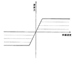
目標減衰力演算部41は、加速度センサ5で検知した上下加速度を積分することで車体の上下速度を得て、この上下速度にスカイフック減衰係数を乗じて必要減衰力を求める。そして、緩衝器2の伸縮速度から減衰力調整機構3としてのコイル26へ電力供給しない場合における当該伸縮速度での最小の減衰力を求めて、必要減衰力からこの最少減衰力を減算して目標減衰力を求める。このように、目標減衰力は、必要減衰力から図3中の減衰特性Lで示した最低減衰力分を除去したものになる。すると、この緩衝器2の減衰特性が緩衝器の伸縮速度が極低速域を超えるとコイル26への供給電流量によらず、傾きが同じであるので、上述したように最低減衰力を減算して求めた目標減衰力と緩衝器の伸縮速度との関係は、図3に示した減衰特性を原点回りに回転させた図4に示すがごとくとなり、緩衝器2の伸縮速度によらず、目標減衰力と減衰力調整機構3へ供給すべき電流量は一対一の関係となる。   The target damping force calculation unit 41 obtains the vertical velocity of the vehicle body by integrating the vertical acceleration detected by the acceleration sensor 5, and obtains the necessary damping force by multiplying this vertical velocity by the Skyhook damping coefficient. Then, the minimum damping force at the expansion / contraction speed when power is not supplied to the coil 26 as the damping force adjusting mechanism 3 from the expansion / contraction speed of the shock absorber 2 is subtracted from the required damping force to obtain the target. Find the damping force. As described above, the target damping force is obtained by removing the minimum damping force component indicated by the damping characteristic L in FIG. 3 from the required damping force. Then, since the damping characteristic of the shock absorber 2 has the same slope regardless of the amount of current supplied to the coil 26 when the expansion / contraction speed of the shock absorber exceeds the extremely low speed range, the minimum damping force is subtracted as described above. The relationship between the target damping force obtained in this way and the expansion / contraction speed of the shock absorber is as shown in FIG. 4 in which the damping characteristic shown in FIG. The damping force and the amount of current to be supplied to the damping force adjusting mechanism 3 have a one-to-one relationship.

つまり、目標減衰力を求めれば、減衰力調整機構3へ供給すべき電流量が決まる関係となる。なお、緩衝器2の伸縮速度は、上記ストロークセンサ6で検知した緩衝器2のストローク(伸縮変位)を微分することで得ることができるが、車輪を支持するスピンドル等に上下加速度を検知する加速度センサを設け、当該車輪の上下加速度を積分して車輪の上下速度を得て、車体の上下速度と車輪の上下速度との差をとって緩衝器2の伸縮速度を得るようにしてもよい。   That is, if the target damping force is obtained, the amount of current to be supplied to the damping force adjusting mechanism 3 is determined. The expansion / contraction speed of the shock absorber 2 can be obtained by differentiating the stroke (stretching displacement) of the shock absorber 2 detected by the stroke sensor 6, but the acceleration for detecting the vertical acceleration by a spindle or the like that supports the wheel. A sensor may be provided to integrate the vertical acceleration of the wheel to obtain the vertical speed of the wheel, and the difference between the vertical speed of the vehicle body and the vertical speed of the wheel may be taken to obtain the expansion / contraction speed of the shock absorber 2.

このように制御装置4は、加速度センサ5で検知した上下加速度を積分して車体の上下速度を演算し、ストロークセンサ6で検知した緩衝器2のストロークを微分して緩衝器2の伸縮速度を演算し、上下速度にスカイフック減衰係数を乗じて必要減衰力を求め、緩衝器2の伸縮速度から当該伸縮速度における緩衝器2の最低減衰力を求め、必要減衰力から最低減衰力を減算して目標減衰力を求める。さらに、この目標減衰力から減衰力調整機構3としてのコイル26へ供給する電流量に対応する目標電流指令値を求めるが、こうして求めた目標減衰力から直接減衰力調整機構3へ供給する電流量を求めると、目標減衰力が緩衝器2の伸縮速度が極低速域にあって実際に緩衝器2が発生できない値に設定されて緩衝器2の伸縮方向が切換って緩衝器が減衰力を発生できる状態となる場合や目標減衰力が緩衝器2の発生可能減衰力範囲内から最大減衰力を超えてしまった場合に、緩衝器2の減衰力の変化が急峻となってしまう。   Thus, the control device 4 calculates the vertical speed of the vehicle body by integrating the vertical acceleration detected by the acceleration sensor 5, differentiates the stroke of the shock absorber 2 detected by the stroke sensor 6, and determines the expansion / contraction speed of the shock absorber 2. Calculate the required damping force by multiplying the vertical speed by the Skyhook damping coefficient, find the minimum damping force of the shock absorber 2 at the stretching speed from the stretching speed of the shock absorber 2, and subtract the minimum damping force from the necessary damping force. To obtain the target damping force. Further, a target current command value corresponding to the amount of current supplied to the coil 26 as the damping force adjusting mechanism 3 is obtained from the target damping force. The amount of current supplied directly to the damping force adjusting mechanism 3 from the thus obtained target damping force. , The target damping force is set to a value at which the expansion / contraction speed of the shock absorber 2 is in an extremely low speed range and the shock absorber 2 cannot actually be generated, and the expansion / contraction direction of the shock absorber 2 is switched so that the shock absorber has a damping force. When it becomes a state where it can be generated, or when the target damping force exceeds the maximum damping force within the range of damping force that can be generated by the shock absorber 2, the change in the damping force of the shock absorber 2 becomes steep.

そこで、本発明にあっては、減衰力調整機構3へ与える指令を補正して緩衝器2の発生減衰力変化を緩和する補正手段としての補正部43を備えている。この補正部43は、この実施の形態では、目標減衰力を補正することで、減衰力調整機構3へ与える指令を補正するようになっており、具体的には、補正部43は、緩衝器2の伸縮速度が所定速度Vp1を超える値に設定される速度閾値Vp2を超えることなく、速度閾値Vp2以下の範囲にある場合と、緩衝器2の伸縮速度が速度閾値Vp2を超えてから0となるまでの場合とで緩衝器2の発生減衰力変化を緩和する伸縮速度を違えて補正を行うようになっている。なお、この補正部43は、目標減衰力の方向と異なる緩衝器2の伸縮方向を正として、目標減衰力の方向と同じ緩衝器2の伸縮方向を負として補正を行うようになっている。 Therefore, in the present invention, the correction unit 43 is provided as a correction unit that corrects a command given to the damping force adjusting mechanism 3 and relaxes a change in the damping force generated by the shock absorber 2. In this embodiment, the correction unit 43 corrects a command to be given to the damping force adjusting mechanism 3 by correcting the target damping force. Specifically, the correcting unit 43 includes a shock absorber. The expansion / contraction speed of the shock absorber 2 exceeds the speed threshold V p2 when the expansion / contraction speed of the shock absorber 2 is within the speed threshold V p2 without exceeding the speed threshold V p2 set to a value exceeding the predetermined speed V p1. The correction is performed by changing the expansion / contraction speed for relieving a change in the damping force generated by the shock absorber 2 between the time when the value is zero and the time when the shock absorber 2 is zero. In addition, this correction | amendment part 43 correct | amends by making the expansion / contraction direction of the buffer 2 different from the direction of the target damping force into positive, and making the expansion / contraction direction of the buffer 2 the same as the direction of target damping force negative.

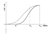
まず、緩衝器2の伸縮速度が所得速度Vp1を超える値に設定される速度閾値Vp2を超えることなく、速度閾値Vp2以下の範囲内である場合の補正部43の処理について説明する。具体的には、補正部43は、目標減衰力の方向(目標減衰力が緩衝器2に指示する減衰力発生方向)と逆向きの緩衝器2の伸縮方向を正とし、緩衝器2の伸縮速度をxとすると、緩衝器2の伸縮速度xが0≦x≦Vp1/2の範囲にあるときには、補正係数αをα=2x/Vp1 を演算して求め、緩衝器2の伸縮速度xがVp1/2<x≦Vp1の範囲にあるときには、補正係数αをα=−2(x−Vp1/Vp1 +1を演算して求め、こうして求めた補正係数αに上記目標減衰力を乗じて目標減衰力を補正する。なお、緩衝器2は、パッシブな緩衝器であり、自発的に推力を発生することができない。目標減衰力が緩衝器2の伸縮方向と同じ方向である場合、つまり、目標減衰力の方向が緩衝器の伸縮を助成する方向である場合、緩衝器2は目標減衰力と同方向へ減衰力を発揮することができないので、緩衝器2の発生減衰力を限りなく小さくする、つまり、最小とする必要がある。そのため、目標減衰力の方向と緩衝器2の伸縮方向が同一の場合、具体的には、補正部43で採用する緩衝器2の伸縮方向の符号の定義に則って、伸縮速度xが負の値を採る場合、補正部43は、補正係数αを0として目標減衰力を補正し、補正後の目標減衰力は0となる。また、補正部43は、緩衝器2の伸縮速度xが所定速度Vp1を超える範囲である場合、緩衝器2の伸縮方向と目標減衰力の方向とが異なり、目標減衰力を補正する必要がないので補正係数αを1として補正後の目標減衰力を演算する。 First, the processing of the correction unit 43 when the expansion / contraction speed of the shock absorber 2 does not exceed the speed threshold V p2 set to a value exceeding the income speed V p1 and is within the range of the speed threshold V p2 will be described. Specifically, the correcting unit 43 sets the expansion / contraction direction of the shock absorber 2 in the opposite direction to the direction of the target damping force (the damping force generation direction in which the target damping force instructs the shock absorber 2), and the expansion / contraction of the shock absorber 2 If the speed is x, when the expansion rate x of the shock absorber 2 is in the range of 0 ≦ x ≦ V p1 / 2 is determined by calculating the correction coefficient α α = 2x 2 / V p1 2, the shock absorber 2 When the expansion / contraction speed x is in the range of V p1 / 2 <x ≦ V p1 , the correction coefficient α is obtained by calculating α = −2 (x−V p1 ) 2 / V p1 2 +1, and the correction coefficient thus obtained is obtained. The target damping force is corrected by multiplying α by the target damping force. The shock absorber 2 is a passive shock absorber and cannot spontaneously generate thrust. When the target damping force is the same direction as the expansion / contraction direction of the shock absorber 2, that is, when the direction of the target damping force is a direction that assists the expansion / contraction of the shock absorber, the shock absorber 2 has a damping force in the same direction as the target damping force. Therefore, it is necessary to minimize the generated damping force of the shock absorber 2, that is, to minimize it. Therefore, when the direction of the target damping force and the expansion / contraction direction of the shock absorber 2 are the same, specifically, the expansion / contraction speed x is negative in accordance with the definition of the sign of the expansion / contraction direction of the shock absorber 2 employed in the correction unit 43. When the value is taken, the correction unit 43 corrects the target damping force by setting the correction coefficient α to 0, and the corrected target damping force becomes 0. Further, when the expansion / contraction speed x of the shock absorber 2 is in a range exceeding the predetermined speed V p1 , the correction unit 43 needs to correct the target damping force because the expansion / contraction direction of the shock absorber 2 is different from the direction of the target damping force. Since there is no correction, the correction coefficient α is set to 1, and the corrected target damping force is calculated.

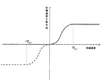
すると、目標減衰力の方向が緩衝器2を伸長させる方向であって目標減衰力をある一定の値とする場合を例にして説明すると、補正後の目標減衰力は、図5中の実線で示すように、緩衝器2が伸長作動を呈していて目標減衰力の方向に一致している場合には0となり、緩衝器2が収縮作動を呈していて目標減衰力の方向と異なるとともに緩衝器2の発生上限減衰力以下であって、緩衝器2の伸縮速度が0から所定速度Vp1以下である場合には、緩衝器2の伸縮速度xよって変化し、緩衝器2の伸縮速度xが所定速度Vp1を超えると、補正係数が1となって補正後の目標減衰力は目標減衰力演算部41で演算した目標減衰力と一致するようになる。ここで、所定速度Vp1は、補正後の目標減衰力閾値が緩衝器2の発生可能減衰力範囲内に収まるように設定されるとよく、目標減衰力に対して変動しない一定の値をとるようにしてもよいし、目標減衰力の大きさによって変化するようにしてもよい。また、目標減衰力の方向が緩衝器2を収縮させる方向であって目標減衰力をある一定の値とする場合を例にして説明すると、補正後の目標減衰力は、図5中の破線で示すように、緩衝器2が収縮作動を呈していて目標減衰力の方向に一致している場合には0となり、緩衝器2が伸長作動を呈していて目標減衰力の方向と異なるとともに緩衝器2の発生上限減衰力以下であって、緩衝器2の伸縮速度が0から所定速度Vp1以下である場合には、緩衝器2の伸縮速度xよって変化し、緩衝器2の伸縮速度xが所定速度Vp1を超えると、補正係数が1となって補正後の目標減衰力は目標減衰力演算部41で演算した目標減衰力と一致するようになる。なお、伸縮速度xは、目標減衰力の方向と逆向きの緩衝器2の伸縮方向を正としているが、図5中では、緩衝器2の伸長方向の速度を負の値とし、緩衝器2を収縮させる方向の減衰力を負の値としているので、補正後の目標減衰力は破線のようになる。 Then, a case where the direction of the target damping force is a direction in which the shock absorber 2 is extended and the target damping force is set to a certain value will be described as an example. The corrected target damping force is indicated by a solid line in FIG. As shown, when the shock absorber 2 exhibits an extension operation and coincides with the direction of the target damping force, it becomes 0, and the shock absorber 2 exhibits a contraction operation and differs from the direction of the target damping force. 2 and below the upper limit damping force of 2 and the expansion / contraction speed of the shock absorber 2 is from 0 to a predetermined speed V p1 or less, it varies depending on the expansion / contraction speed x of the shock absorber 2, and the expansion / contraction speed x of the shock absorber 2 is When the speed exceeds the predetermined speed V p1 , the correction coefficient becomes 1, and the corrected target damping force coincides with the target damping force calculated by the target damping force calculation unit 41. Here, the predetermined speed V p1 is preferably set so that the corrected target damping force threshold is within the range of the damping force that can be generated by the shock absorber 2, and takes a constant value that does not vary with respect to the target damping force. Alternatively, it may be changed depending on the magnitude of the target damping force. Further, the case where the direction of the target damping force is a direction in which the shock absorber 2 is contracted and the target damping force is set to a certain value will be described as an example. The corrected target damping force is indicated by a broken line in FIG. As shown, when the shock absorber 2 exhibits a contraction operation and coincides with the direction of the target damping force, it becomes 0, and the shock absorber 2 exhibits an extension operation and differs from the direction of the target damping force. 2 and below the upper limit damping force of 2 and the expansion / contraction speed of the shock absorber 2 is from 0 to a predetermined speed V p1 or less, it varies depending on the expansion / contraction speed x of the shock absorber 2, and the expansion / contraction speed x of the shock absorber 2 is When the speed exceeds the predetermined speed V p1 , the correction coefficient becomes 1, and the corrected target damping force coincides with the target damping force calculated by the target damping force calculation unit 41. The expansion / contraction speed x is positive in the expansion / contraction direction of the shock absorber 2 in the direction opposite to the direction of the target damping force, but in FIG. Since the damping force in the direction of contracting is a negative value, the corrected target damping force is as shown by the broken line.

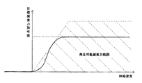
目標減衰力の方向が緩衝器2を伸長させる方向である場合を例にすると、図6に示すように、目標減衰力が最大であり減衰力調整機構3への供給電流量が最大となる場合の減衰特性k1に対して緩衝器2が出力可能な減衰力範囲は、減衰特性k1と伸縮速度軸との間となり、これに補正後の目標減衰力の軌跡G1を当該出力可能範囲内に収める場合には、所定速度Vp1をVp1(1)以上にする必要がある。これに対して、目標減衰力を小さくして、減衰力調整機構3への供給電流量も小さくして減衰特性k2となる場合、補正後の目標減衰力の軌跡G2を当該出力可能範囲内に収める場合には、所定速度をVp1(2)以上にする必要がある。さらに目標減衰力を小さくして、減衰力調整機構3への供給電流量も小さくして減衰特性k3となる場合、補正後の目標減衰力の軌跡G3を当該出力可能範囲内に収める場合には、所定速度をVp1(3)以上にする必要がある。したがって、この緩衝器2の場合、目標減衰力が大きくなればなるほど、所定速度Vp1を大きくしなければならないことが分かる。このように目標減衰力が小さい場合には、補正後の目標減衰力が目標減衰力に等しくなる所定速度Vp1も小さくすることができ、このように目標減衰力をパラメータとして所定速度Vp1を変化させることで、補正後の目標減衰力をいち早く補正前の目標減衰力に追従させることができるメリットがある。 Taking the case where the direction of the target damping force is the direction in which the shock absorber 2 is extended as an example, as shown in FIG. 6, the target damping force is maximum and the amount of current supplied to the damping force adjustment mechanism 3 is maximum. The damping force range that can be output by the shock absorber 2 with respect to the damping characteristic k1 is between the damping characteristic k1 and the expansion / contraction speed axis, and the corrected target damping force locus G1 falls within this output possible range. In this case, the predetermined speed V p1 needs to be equal to or higher than V p1 (1). On the other hand, when the target damping force is reduced and the amount of current supplied to the damping force adjustment mechanism 3 is reduced to become the damping characteristic k2, the corrected target damping force locus G2 is within the output possible range. In the case of storing, it is necessary to set the predetermined speed to V p1 (2) or more. When the target damping force is further reduced and the amount of current supplied to the damping force adjusting mechanism 3 is reduced to obtain the damping characteristic k3, the corrected target damping force locus G3 is within the output possible range. The predetermined speed needs to be V p1 (3) or more. Therefore, in the case of this shock absorber 2, it can be seen that the greater the target damping force, the greater the predetermined speed Vp1 must be. In this case the target damping force is small, the predetermined speed V p1 of the target damping force after correction becomes equal to the target damping force can also be reduced, thus the predetermined speed V p1 of the target damping force as a parameter By changing it, there is an advantage that the corrected target damping force can quickly follow the target damping force before correction.

つづいて、緩衝器2の伸縮速度xが速度閾値Vp2を超えてから0となるまでの場合における補正部43の処理について説明する。具体的には、補正部43は、当該速度閾値Vp2から上記所定速度Vp1を差し引きした値である速度閾値Vp2と所定速度Vp1の差分をβとすると、一度、伸縮速度xがx>Vp2を満たすと伸縮速度xが0になるまでは、緩衝器2の伸縮速度xがβ≦x≦Vp2−Vp1/2の範囲にあるときは、補正係数αをα=2(x−β)/Vp1 を演算して求め、緩衝器2の伸縮速度xがVp2−Vp1/2<x≦Vp2の範囲にあるときは、補正係数αを、α=−2(x−β−Vp1/Vp1 +1を演算して求めるとともに、緩衝器2の伸縮速度xが0≦x<βの範囲にあるときは、補正係数αを0とし、こうして求めた補正係数αに上記目標減衰力を乗じて目標減衰力を補正する。なお、緩衝器2は、パッシブな緩衝器であり、自発的に推力を発生することができない。目標減衰力が緩衝器2の伸縮方向と同じ方向である場合、緩衝器2は目標減衰力と同方向へ減衰力を発揮することができないので、緩衝器2の発生減衰力を限りなく小さくする必要がある。そのため、目標減衰力の方向と緩衝器2の伸縮方向が同一の場合、補正部43は、補正係数αを0として目標減衰力を補正し、補正後の目標減衰力は0となる。また、補正部43は、緩衝器2の伸縮速度xが速度閾値Vp2を超える範囲である場合、緩衝器2の伸縮方向と目標減衰力の方向とが異なり、目標減衰力を補正する必要がないので補正係数αを1として補正後の目標減衰力を演算する。 Next, the processing of the correction unit 43 when the expansion / contraction speed x of the shock absorber 2 exceeds the speed threshold value Vp2 and becomes 0 will be described. Specifically, the correction unit 43, when the difference of the speed threshold V p2 and the predetermined speed V p1 from the speed threshold V p2 is a value obtained by subtracting the predetermined speed V p1 and beta, once stretching speed x is x If the expansion / contraction speed x of the shock absorber 2 is in the range of β ≦ x ≦ V p2 −V p1 / 2 until the expansion / contraction speed x reaches 0 when> V p2 is satisfied, the correction coefficient α is set to α = 2 ( x−β) 2 / V p12 2 is obtained by calculation, and when the expansion / contraction speed x of the shock absorber 2 is in the range of V p2 −V p1 / 2 <x ≦ V p2 , the correction coefficient α is set to α = − 2 (x−β−V p1 ) 2 / V p1 2 +1 is calculated, and when the expansion / contraction speed x of the shock absorber 2 is in the range of 0 ≦ x <β, the correction coefficient α is set to 0, and The target damping force is corrected by multiplying the obtained correction coefficient α by the target damping force. The shock absorber 2 is a passive shock absorber and cannot spontaneously generate thrust. When the target damping force is in the same direction as the expansion / contraction direction of the shock absorber 2, the shock absorber 2 cannot exert the damping force in the same direction as the target damping force, and therefore the generated damping force of the shock absorber 2 is reduced as much as possible. There is a need. Therefore, when the direction of the target damping force and the expansion / contraction direction of the shock absorber 2 are the same, the correction unit 43 corrects the target damping force by setting the correction coefficient α to 0, and the corrected target damping force becomes 0. Further, when the expansion / contraction speed x of the shock absorber 2 is in a range exceeding the speed threshold value V p2 , the correction unit 43 needs to correct the target damping force because the expansion / contraction direction of the shock absorber 2 is different from the direction of the target damping force. Since there is no correction, the correction coefficient α is set to 1, and the corrected target damping force is calculated.

以上より、緩衝器2の伸縮速度xが速度閾値Vp2を超えてから0となるまでの場合、目標減衰力の方向が緩衝器2を伸長させる方向であって目標減衰力をある一定の値とする状況を例にすると、補正後の目標減衰力は、図7中の実線で示すように、緩衝器2が収縮作動を呈していて目標減衰力の方向と異なるとともに緩衝器2の発生上限減衰力以下であって、緩衝器2の伸縮速度がβから速度閾値Vp2以下である場合には、緩衝器2の伸縮速度xよって変化し、緩衝器2の伸縮速度xが速度閾値Vp2を超えると、補正係数が1となって補正後の目標減衰力は目標減衰力演算部41で演算した目標減衰力と一致するようになる。なお、目標減衰力の方向が緩衝器2を収縮させる方向である場合には、補正後の目標減衰力は、図7中の破線で示すようになる。図7中では、緩衝器2の伸長方向の速度を負の値とし、緩衝器2を収縮させる方向の減衰力を負の値としているので、補正後の目標減衰力は破線のようになる。 From the above, when the expansion / contraction speed x of the shock absorber 2 exceeds the speed threshold value V p2 and becomes 0, the direction of the target damping force is the direction in which the shock absorber 2 is extended and the target damping force is a certain value. As an example, the corrected target damping force is different from the direction of the target damping force as the shock absorber 2 exhibits contraction operation as shown by the solid line in FIG. a less damping force, when stretching speed of the shock absorber 2 is equal to or less than the speed threshold V p2 from β is buffer 2 of the telescopic velocity x Thus changes, shock absorber 2 of the telescopic speed x speed threshold V p2 Exceeds the value, the correction coefficient becomes 1, and the corrected target damping force coincides with the target damping force calculated by the target damping force calculation unit 41. When the direction of the target damping force is a direction in which the shock absorber 2 is contracted, the corrected target damping force is as indicated by a broken line in FIG. In FIG. 7, the speed in the extension direction of the shock absorber 2 is a negative value, and the damping force in the direction of contracting the shock absorber 2 is a negative value, so that the corrected target damping force is as shown by a broken line.

さらに、上記補正部43の補正処理を実際の緩衝器2の動きに即して説明する。目標減衰力の方向が変わらず、緩衝器2の伸縮速度xが負の値から正の値に転じて速度が増加し、さらに、反転して負に転じる場合について、補正部43による目標減衰力の補正については、図8に示すようになる。緩衝器2の伸縮速度xが負の値から正の値に転じて速度が増加していく過程では、図8中の実線で示すように、伸縮速度xが負の場合には、補正係数α=0として補正され、速度閾値Vp2を超えるまでは0≦x≦Vp1の範囲では上記したように補正され、所定速度Vp1を超えると補正係数α=1として補正される。その後、伸縮速度xが増加して速度閾値Vp2を超え、伸縮速度xが遅くなって、やがて0になり、伸縮方向が反転して伸縮速度xが負になる過程では、図8中破線で示すように、伸縮速度xがβ≦x≦Vp2−Vp1/2の範囲にあると上記のごとく補正され、所定速度を超えると補正係数α=1として補正され、伸縮速度xがx<βの範囲では補正係数α=0として補正され、伸縮速度xが負となると補正係数α=0として補正される。つまり、緩衝器2の伸縮速度xが速度閾値Vp2を超えた場合における補正係数αは、図8に示すように、上記した緩衝器2の伸縮速度xが速度閾値Vp2を超えない場合における補正係数αに対して、当該速度閾値Vp2から上記所定速度Vp1を差し引きした値である速度閾値Vp2と所定速度Vp1の差分βだけ速度増側となる図中右方へオフセットされている。すなわち、伸縮速度xが速度閾値Vp2を超えない場合には、補正手段である補正部43は、上記緩衝器2の伸縮速度が0および所定速度Vp1における緩衝器の発生減衰力の変化を緩和するが、伸縮速度xが速度閾値Vp2を超えると伸縮速度xが0になるまでは、緩衝器2の発生減衰力変化を緩和する伸縮速度を上記速度閾値Vp2と上記所定速度Vp1の差分βだけ速度増側へオフセットして発生減衰力を補正し、差分βから伸縮速度xが0までの範囲において発生減衰力を最小にするようになっている。 Further, the correction process of the correction unit 43 will be described in accordance with the actual movement of the shock absorber 2. In the case where the direction of the target damping force does not change and the expansion / contraction speed x of the shock absorber 2 changes from a negative value to a positive value to increase the speed and then reverses and changes to negative, the target damping force by the correcting unit 43 This correction is as shown in FIG. In the process in which the expansion / contraction speed x of the shock absorber 2 changes from a negative value to a positive value and the speed increases, as shown by the solid line in FIG. 8, when the expansion / contraction speed x is negative, the correction coefficient α Is corrected as described above in the range of 0 ≦ x ≦ V p1 until the speed threshold V p2 is exceeded, and is corrected as a correction coefficient α = 1 if the speed exceeds the predetermined speed V p1 . Thereafter, in the process in which the expansion / contraction speed x increases and exceeds the speed threshold V p2 , the expansion / contraction speed x becomes slow and eventually becomes 0, and the expansion / contraction direction reverses and the expansion / contraction speed x becomes negative, the broken line in FIG. As shown, when the expansion / contraction speed x is in the range of β ≦ x ≦ V p2 −V p1 / 2, the correction is made as described above. When the expansion speed exceeds the predetermined speed, the correction coefficient α = 1 is corrected, and the expansion / contraction speed x is x < In the range of β, the correction coefficient α = 0 is corrected, and when the expansion / contraction speed x becomes negative, the correction coefficient α = 0 is corrected. That is, the correction coefficient α when the expansion / contraction speed x of the shock absorber 2 exceeds the speed threshold V p2 is as shown in FIG. 8 when the expansion / contraction speed x of the shock absorber 2 does not exceed the speed threshold V p2 . relative correction coefficient alpha, is offset from the speed threshold V p2 to the right in the drawing which is a difference β only speed up the side of the predetermined speed V speed threshold V p2 p1 is a value obtained by subtracting a predetermined speed V p1 Yes. That is, when the expansion / contraction speed x does not exceed the speed threshold value V p2 , the correction unit 43 serving as a correction unit changes the generated damping force of the shock absorber when the expansion speed of the shock absorber 2 is 0 and the predetermined speed V p1 . However, when the expansion / contraction speed x exceeds the speed threshold V p2 , the expansion / contraction speed for relaxing the damping force change generated by the shock absorber 2 is set to the speed threshold V p2 and the predetermined speed V p1 until the expansion / contraction speed x becomes zero. The generated damping force is corrected by offsetting the difference β to the speed increasing side, and the generated damping force is minimized in the range from the difference β to the expansion / contraction speed x.

このようにすることで、伸縮速度xが速度閾値Vp2を超える場合には、伸縮速度xが減少に転じると、早い段階から目標減衰力が補正されて減少に転じるようになり、この目標減衰力が後段の目標電流指令値演算部44、ドライバ45を介して指令となって減衰力調整機構3へ供給されるので、図9に示すように、当該指令も伸縮速度xが減少に転じると早い段階から0へ変化して、減衰力調整機構3へ与える指令に対して減衰力調整機構3に流れる電流が遅れても、緩衝器2の伸縮速度xが0となるときには、減衰力調整機構3におけるコイル26に流れる実電流を0にすることができる。なお、図9中、実線は、補正手段としての補正部43によって目標減衰力を補正することで補正された指令を示しており、破線は、減衰力調整機構3のコイル26に流れている実電流を示している。 By doing in this way, when the expansion / contraction speed x exceeds the speed threshold value Vp2 , when the expansion / contraction speed x starts to decrease, the target damping force is corrected from an early stage and starts to decrease. Since the force is supplied as a command to the damping force adjusting mechanism 3 via the target current command value calculation unit 44 and the driver 45 in the subsequent stage, as shown in FIG. 9, when the expansion / contraction speed x starts to decrease as shown in FIG. Even if the current flowing through the damping force adjusting mechanism 3 is delayed with respect to the command given to the damping force adjusting mechanism 3 by changing from 0 to 0, the damping force adjusting mechanism can be used when the expansion / contraction speed x of the shock absorber 2 becomes zero. 3, the actual current flowing through the coil 26 can be reduced to zero. In FIG. 9, the solid line indicates a command corrected by correcting the target damping force by the correcting unit 43 serving as a correcting unit, and the broken line indicates the actual current flowing in the coil 26 of the damping force adjusting mechanism 3. Current is shown.

ここで、速度閾値Vp2は、上記所定速度Vp1を超える値に設定されればよいのであるが、所定速度Vp1との差分βが小さすぎると、減衰力調整機構3におけるコイル26に緩衝器2の伸縮速度が0であるときに電流が残留してしまうので、減衰力調整機構3および電流を供給するドライバ45とでなる回路における時定数(この実施の形態の場合、コイル26を含めたドライバ45の回路の時定数)と車両走行中のばね下振動周波数から充分に緩衝器2の伸縮速度が0のときに上記残留電流が発生しない程度に設定されれば良い。 Here, the speed threshold V p2 is is the may be set to a value greater than the predetermined speed V p1, the difference β between the predetermined speed V p1 is too low, the buffer to the coil 26 in the damping force adjusting mechanism 3 Since the current remains when the expansion / contraction speed of the device 2 is 0, the time constant in the circuit composed of the damping force adjusting mechanism 3 and the driver 45 for supplying the current (in this embodiment, including the coil 26) It is sufficient that the residual current is not generated when the expansion / contraction speed of the shock absorber 2 is zero, based on the time constant of the driver 45 circuit) and the unsprung vibration frequency during vehicle travel.

なお、速度閾値Vp2についても、緩衝器2の伸縮速度が0のときに上記残留電流が発生しない限りにおいて、所定速度Vp1と同様に、目標減衰力の大きさに応じて、その値が変化するようにされてもよい。 As for the speed threshold V p2 , as long as the residual current does not occur when the expansion / contraction speed of the shock absorber 2 is 0, the value of the speed threshold V p2 is set according to the magnitude of the target damping force as in the case of the predetermined speed V p1. It may be made to change.

引き続き、補正部43の後段の目標電流指令値演算部44は、補正後の目標減衰力から電流量を求める。目標電流指令値演算部44で求めた目標電流指令値は、ドライバ45へ入力され、ドライバ45は、目標電流指令値に対応する電流を指令として減衰力調整機構3へ出力する。上記した演算を行って制御装置4は、減衰力調整機構3を介して緩衝器2の減衰力を調節する。つまり、補正部43は、この場合、目標減衰力を求める目標減衰力演算部41の後段にあって、目標減衰力を補正して減衰力調整機構3へ与える指令を補正している。   Subsequently, the target current command value calculation unit 44 subsequent to the correction unit 43 obtains the amount of current from the corrected target damping force. The target current command value obtained by the target current command value calculation unit 44 is input to the driver 45, and the driver 45 outputs the current corresponding to the target current command value as a command to the damping force adjustment mechanism 3. The control device 4 adjusts the damping force of the shock absorber 2 through the damping force adjusting mechanism 3 by performing the above-described calculation. That is, in this case, the correction unit 43 is subsequent to the target damping force calculation unit 41 for obtaining the target damping force, and corrects the command given to the damping force adjustment mechanism 3 by correcting the target damping force.

目標電流指令値演算部44は、具体的には、上記目標減衰力から目標電流指令値を得るマップ演算を行う。なお、この実施の形態では、目標電流指令値演算部44は、マップ演算を行わずに目標減衰力から目標電流指令値を求めることもできる。   Specifically, the target current command value calculation unit 44 performs map calculation to obtain a target current command value from the target damping force. In this embodiment, the target current command value calculation unit 44 can also obtain the target current command value from the target damping force without performing the map calculation.

上記マップ演算に使用するマップは、2つあり、具体的には、緩衝器2が収縮作動する場合に使用される収縮側マップM1と、緩衝器2が伸長作動する場合に使用される伸長側マップM2がある。つまり、マップは、緩衝器2の伸縮方向毎に用意されている。収縮側マップM1は、図10に示すように、目標減衰力の方向が緩衝器2の伸縮方向と同じ方向である場合、つまり、緩衝器2が収縮しており目標減衰力が緩衝器2に収縮方向の減衰力の発生を指示している場合に対応して目標減衰力の変化に対して一定値をとる出力下限ラインA1と、目標減衰力の方向が緩衝器2の伸縮方向が異なるものの出力上限を上回る場合、つまり、緩衝器2が収縮しており目標減衰力が緩衝器2に伸長方向の減衰力の発生を指示しているが出力上限を上回る場合に対応して目標減衰力の変化に対して一定値をとる出力上限ラインB1と、出力下限ラインA1と出力上限ラインB1とを結ぶとともに、目標減衰力の方向が緩衝器2の伸縮方向が異なり緩衝器2が出力可能な場合、つまり、緩衝器2が収縮しており目標減衰力が緩衝器2に伸長方向の減衰力の発生を指示しており出力可能範囲にある場合に対応して目標減衰力に対して比例的に変化する出力可能ラインC1を備えている。   There are two maps used for the map calculation. Specifically, the contraction side map M1 used when the shock absorber 2 operates in contraction, and the expansion side used when the shock absorber 2 operates in expansion. There is a map M2. That is, a map is prepared for each expansion / contraction direction of the shock absorber 2. As shown in FIG. 10, the contraction-side map M <b> 1 shows that when the direction of the target damping force is the same direction as the expansion / contraction direction of the shock absorber 2, that is, the shock absorber 2 is contracted and the target damping force is applied to the shock absorber 2. Corresponding to the case where the generation of the damping force in the contraction direction is instructed, the output lower limit line A1 that takes a constant value with respect to the change in the target damping force, and the direction of the target damping force is different from the expansion / contraction direction of the shock absorber 2. When the output upper limit is exceeded, that is, when the shock absorber 2 is contracted and the target damping force instructs the shock absorber 2 to generate a damping force in the extension direction, the target damping force When the output upper limit line B1 that takes a constant value with respect to the change, the output lower limit line A1, and the output upper limit line B1 are connected, and the direction of the target damping force is different from the expansion / contraction direction of the shock absorber 2, and the shock absorber 2 can output. That is, shock absorber 2 is contracted Damping force and an output enable line C1 which corresponds proportionally changes with respect to the target damping force when in the output range and instructs the generation of the damping force in the expanding direction to the shock absorber 2.

対して、伸長側マップM2は、図11に示すように、目標減衰力の方向が緩衝器2の伸縮方向と同じ方向である場合、つまり、緩衝器2が伸長しており目標減衰力が緩衝器2に伸長方向の減衰力の発生を指示している場合に対応して目標減衰力の変化に対して一定値をとる出力下限ラインA2と、目標減衰力の方向が緩衝器2の伸縮方向が異なるものの出力上限を上回る場合、つまり、緩衝器2が伸長しており目標減衰力が緩衝器2に収縮方向の減衰力の発生を指示しているが出力上限を上回る場合に対応して目標減衰力の変化に対して一定値をとる出力上限ラインB2と、出力下限ラインA2と出力上限ラインB2とを結ぶとともに、目標減衰力の方向が緩衝器2の伸縮方向が異なり緩衝器2が出力可能な場合、つまり、緩衝器2が伸長しており目標減衰力が緩衝器2に収縮方向の減衰力の発生を指示しており出力可能範囲にある場合に対応して目標減衰力に対して比例的に変化する出力可能ラインC2を備えている。   On the other hand, as shown in FIG. 11, in the extension side map M2, the direction of the target damping force is the same as the expansion / contraction direction of the shock absorber 2, that is, the shock absorber 2 is extended and the target damping force is buffered. Corresponding to the case where the generation of the damping force in the extension direction is instructed to the damper 2, the output lower limit line A2 that takes a constant value with respect to the change in the target damping force, and the direction of the target damping force is the expansion / contraction direction of the shock absorber 2 Is different from the upper limit of the output, that is, the shock absorber 2 is extended and the target damping force instructs the shock absorber 2 to generate a damping force in the contraction direction, but the target exceeds the output upper limit. The output upper limit line B2 that takes a constant value with respect to the change of the damping force, the output lower limit line A2, and the output upper limit line B2 are connected, and the direction of the target damping force is different from the expansion / contraction direction of the shock absorber 2, and the shock absorber 2 outputs If possible, that is, the shock absorber 2 is extended The output possible line C2 that changes proportionally with respect to the target damping force is provided corresponding to the case where the target damping force instructs the shock absorber 2 to generate the damping force in the contraction direction and is within the output possible range. .

なお、収縮側マップM1および伸長側マップM2において、目標減衰力は緩衝器2に伸長方向に減衰力を発生させる値を正とし、つまり、収縮を妨げる減衰力を緩衝器2に発揮させる目標減衰力の値を正としてあり、反対方向の減衰力を発生させる目標減衰力を負としている。この実施の形態で目標電流指令値が目標減衰力の如何によらず、0以上の値となるのは、減衰力調整機構3への電流供給によって減衰係数を調節しているからである。上記したところでは、目標減衰力が緩衝器2の出力可能範囲にある場合、減衰力調整機構3へ与える電流と緩衝器2の発生減衰力が比例関係にあるので、上記収縮側マップM1および伸長側マップM2において出力可能ラインC1,C2は、目標電流指令値が電流値目標減衰力に応じて比例的に変化するので直線となるが、緩衝器2の発生減衰力と電流との関係が非線形である場合には、出力可能ラインC1,C2も発生減衰力と電流との関係に即したものとされればよい。つまり、緩衝器2の発生減衰力と電流との関係を示す線が途中で屈曲点を持っているのであれば、出力可能ラインC1,C2も途中に屈曲点を持つ折れ線で示され、緩衝器2の発生減衰力と電流との関係を示す線が曲線であれば、出力可能ラインC1,C2も曲線で示されることになる。   In the contraction side map M1 and the expansion side map M2, the target damping force is a positive value that causes the shock absorber 2 to generate a damping force in the expansion direction, that is, the target damping force that causes the shock absorber 2 to exert a damping force that prevents contraction. The force value is positive, and the target damping force that generates damping force in the opposite direction is negative. In this embodiment, the target current command value becomes 0 or more regardless of the target damping force because the damping coefficient is adjusted by supplying current to the damping force adjusting mechanism 3. As described above, when the target damping force is within the output possible range of the shock absorber 2, the current applied to the damping force adjusting mechanism 3 and the generated damping force of the shock absorber 2 are in a proportional relationship. The output possible lines C1 and C2 in the side map M2 are linear because the target current command value changes proportionally according to the current value target damping force, but the relationship between the generated damping force of the shock absorber 2 and the current is nonlinear. In this case, the output possible lines C1 and C2 may be set in accordance with the relationship between the generated damping force and the current. That is, if the line indicating the relationship between the generated damping force of the shock absorber 2 and the current has a bending point in the middle, the output possible lines C1 and C2 are also indicated by broken lines having a bending point in the middle. If the line indicating the relationship between the generated damping force 2 and the current is a curve, the output possible lines C1 and C2 are also indicated by the curve.

上述したように緩衝器2は、パッシブな緩衝器であり、自発的に推力を発生することができないので、目標減衰力の方向が緩衝器2の伸縮方向と同じ方向である場合、緩衝器2は目標減衰力の方向と同方向へ減衰力を発揮することができず、緩衝器2の発生減衰力を限りなく小さくする必要がある。そのため、緩衝器2の減衰力を最小とすべく、この実施の形態では目標電流指令値を0とする。すなわち、出力下限ラインA1,A2は、この場合、0で一定となる。   As described above, the shock absorber 2 is a passive shock absorber and cannot generate a thrust spontaneously. Therefore, when the direction of the target damping force is the same as the expansion and contraction direction of the shock absorber 2, the shock absorber 2. Cannot exert a damping force in the same direction as the target damping force, and it is necessary to make the damping force generated by the shock absorber 2 as small as possible. Therefore, in order to minimize the damping force of the shock absorber 2, the target current command value is set to 0 in this embodiment. That is, the output lower limit lines A1 and A2 are constant at 0 in this case.

また、目標減衰力の方向が緩衝器2の伸縮方向と逆方向である場合であって、緩衝器2の減衰力の出力上限を上回る場合、緩衝器2の発生減衰力を目標減衰力に追随させることができないが、緩衝器2の発生減衰力を限りなく目標減衰指令値に近づけるため、緩衝器2の減衰力を最大とすべく、この実施の形態では目標電流指令値を所定の上限値とする。すなわち、出力上限ラインB1,B2は、この場合、ハードウェア上の電流値の上限値で一定となる。   Further, when the direction of the target damping force is opposite to the expansion / contraction direction of the shock absorber 2 and exceeds the upper limit of the damping force output of the shock absorber 2, the generated damping force of the shock absorber 2 follows the target damping force. However, in order to maximize the damping force of the shock absorber 2, the target current command value is set to a predetermined upper limit value in order to maximize the damping force of the shock absorber 2. And That is, in this case, the output upper limit lines B1 and B2 are constant at the upper limit value of the current value on the hardware.

そして、目標減衰力の方向が緩衝器2の伸縮方向と逆方向である場合であって、目標減衰力が緩衝器2の出力可能な範囲である場合には、上述したように目標減衰力に対して目標電流指令値が一対一の関係となり、目標減衰力に対して目標電流指令値が比例することになり、出力可能ラインC1,C2は、目標減衰力に対してある傾きをもって比例する。この出力可能ラインC1,C2の傾きは、目標減衰力軸に対する傾きは一定で、減衰力調整機構3への供給電流量と緩衝器2における減衰力との関係に依存して決定される。   When the direction of the target damping force is opposite to the expansion / contraction direction of the shock absorber 2 and the target damping force is within the output range of the shock absorber 2, the target damping force is set to the target damping force as described above. On the other hand, the target current command value has a one-to-one relationship, the target current command value is proportional to the target damping force, and the output possible lines C1 and C2 are proportional to the target damping force with a certain inclination. The inclinations of the output possible lines C1 and C2 are determined depending on the relationship between the amount of current supplied to the damping force adjusting mechanism 3 and the damping force in the shock absorber 2 while the slope with respect to the target damping force axis is constant.

なお、電気粘性流体を用いた緩衝器の場合、収縮側マップM1と伸長側マップM2における縦軸を目標電圧指令値とし、制御装置4は、目標減衰力から目標電圧指令値を求めるようにすればよい。また、減衰力調整機構3が電磁弁であって電流供給を行わない場合に緩衝器2が最大減衰力を発生する場合には、出力下限ラインA1,A2をハードウェア上の電流値の上限値で一定とし、出力上限ラインB1,B2を0で一定とするようなマップとすればよい。   In the case of a shock absorber using an electrorheological fluid, the vertical axis in the contraction side map M1 and the expansion side map M2 is set as the target voltage command value, and the control device 4 is configured to obtain the target voltage command value from the target damping force. That's fine. Further, when the damping force adjusting mechanism 3 is a solenoid valve and the shock absorber 2 generates the maximum damping force when no current is supplied, the output lower limit lines A1 and A2 are set to the upper limit values of the current values on the hardware. And the output upper limit lines B1 and B2 may be constant at 0.

目標電流指令値は、この実施の形態の場合、減衰力調整機構3へ供給する電流値そのものとして説明しているが、たとえば、減衰力調整機構3のコイル26をPWM制御する場合には、目標電流指令値を供給電流値と一対一の関係となるデューティ比として求め、コイル26にPWMパルス電圧を印加するドライバ45へデューティ比でなる目標電流指令値を与えるようにして、減衰力調整機構3への供給電流を制御するようにしてもよい。また、ドライバは、制御装置4側に設けるのではなく、減衰力調整機構3側に設けるようにしてもよい。   In the case of this embodiment, the target current command value is described as the current value supplied to the damping force adjustment mechanism 3 itself. However, for example, when the coil 26 of the damping force adjustment mechanism 3 is PWM-controlled, the target current command value is The current command value is obtained as a duty ratio that has a one-to-one relationship with the supply current value, and the target current command value that is the duty ratio is given to the driver 45 that applies the PWM pulse voltage to the coil 26, so that the damping force adjusting mechanism 3 You may make it control the supply current to. Further, the driver may be provided on the damping force adjusting mechanism 3 side instead of being provided on the control device 4 side.

また、この例では、収縮側マップM1と伸長側マップM2を持っているが、伸長側と収縮側で減衰特性が同じであれば、マップを一つにしておき、目標減衰力の絶対値に対して目標電流指令値或いは目標電圧指令値を求めるようにしてもよい。   Further, in this example, the contraction side map M1 and the expansion side map M2 are provided, but if the attenuation characteristics are the same on the expansion side and the contraction side, the maps are made one and the absolute value of the target damping force is obtained. On the other hand, a target current command value or a target voltage command value may be obtained.

さらに、上記したところでは、減衰力調整機構3へ与える電流量によって緩衝器2の減衰係数が変化する特性となっており、目標減衰力を上記必要減衰力から最低減衰力を減じて求めるようにしているので、収縮側マップM1と伸長側マップM2を持っていればよく、マップ演算も簡単となるが、目標減衰力を上記で言うところの必要減衰力として目標電流指令値或いは目標電圧指令値を求める場合には、緩衝器2の伸縮速度に応じて目標減衰力と目標電流指令値或いは目標電圧指令値との関係の三次元グラフをマップ化しておき、当該三次元マップを用いて求めるようにしてもよいし、複数の緩衝器2の伸縮速度に対して作成した目標減衰力と目標電流指令値或いは目標電圧指令値のマップを保有して、緩衝器2の伸縮速度に応じてマップ間を補間することで目標電流指令値或いは目標電圧指令値を求めるようにしてもよい。   Further, in the above description, the damping coefficient of the shock absorber 2 changes depending on the amount of current applied to the damping force adjusting mechanism 3, and the target damping force is obtained by subtracting the minimum damping force from the required damping force. Therefore, it is only necessary to have the contraction side map M1 and the expansion side map M2, and the map calculation is simplified, but the target current command value or the target voltage command value is used as the required damping force as described above. Is obtained by mapping a three-dimensional graph of the relationship between the target damping force and the target current command value or the target voltage command value according to the expansion / contraction speed of the shock absorber 2, and using the three-dimensional map. Alternatively, a map of the target damping force and the target current command value or the target voltage command value created with respect to the expansion / contraction speeds of the plurality of shock absorbers 2 is stored, and the map corresponding to the expansion / contraction speed of the shock absorber 2 It may be obtained target current command value or target voltage command value by interpolating.

なお、目標電流指令値を求める目標電流指令値演算部44の後段に補正部43を配して、目標電流指令値を補正することで、減衰力調整機構3へ与える指令(電流)を補正するようにしてもよく、また、所定速度については、上述のように目標減衰力に応じて変化させる場合と同様に目標電流指令値の大きさによって変化させるようにしてもよい。   In addition, the correction | amendment part 43 is arrange | positioned in the back | latter stage of the target current command value calculating part 44 which calculates | requires a target current command value, and the command (current) given to the damping force adjustment mechanism 3 is corrected by correcting the target current command value. Alternatively, the predetermined speed may be changed according to the magnitude of the target current command value as in the case of changing according to the target damping force as described above.

上記したところから理解できるように、本実施の形態のサスペンション装置1によれば、目標減衰力を補正することで、補正後の目標減衰力を緩衝器2の発生可能減衰力範囲内に収めつつ、緩衝器2の伸縮速度xが0および所定速度Vp1における緩衝器2の発生減衰力の変化を緩和することができ、また、緩衝器2の伸縮速度xが速度閾値Vp2を超えると、その後、伸縮速度xが減少に転じて0となる場合に、所定速度Vp1を超える速度閾値Vp2と差分βで発生減衰力変化を緩和し、差分βから伸縮速度xが0までの範囲において発生減衰力を最小にするように補正するので、減衰力調整機構3への指令が早い段階から緩衝器2の発生減衰力を最小とする値に変化するから、当該指令に対して減衰力調整機構3に流れる実電流の変化が遅れても、緩衝器2の伸縮速度xが0となるときには、減衰力調整機構3に流れる実電流を0にすることができる。 As can be understood from the above description, according to the suspension device 1 of the present embodiment, the target damping force after correction is kept within the possible damping force range of the shock absorber 2 by correcting the target damping force. , The change in the damping force generated by the shock absorber 2 when the expansion speed x of the shock absorber 2 is 0 and the predetermined speed V p1 can be reduced, and when the expansion speed x of the shock absorber 2 exceeds the speed threshold V p2 , After that, when the expansion / contraction speed x starts to decrease and becomes 0, the generated damping force change is relaxed by the speed threshold V p2 exceeding the predetermined speed V p1 and the difference β, and in the range from the difference β to the expansion / contraction speed x is 0. Since the generated damping force is corrected to be minimized, the command to the damping force adjusting mechanism 3 is changed to a value that minimizes the generated damping force of the shock absorber 2 from an early stage. Change in actual current flowing through mechanism 3 Even late, when the expansion rate x of the damper 2 is 0, the actual current flowing through the damping force adjusting mechanism 3 can be made zero.

このように、緩衝器2の伸縮速度xが0を横切る伸縮方向の切換りに減衰力調整機構3に電流が残留することがないので、緩衝器が意図しない減衰力を発揮することがなくなり、緩衝器2の伸縮速度が0の近傍で減衰力が急変してしまって、車両における乗り心地を悪化させてしまうこともなくなる。したがって、本発明のサスペンション装置1によれば、緩衝器の発生減衰力の急変を確実に緩和して車両における乗り心地を向上することができるのである。   Thus, since the current does not remain in the damping force adjusting mechanism 3 when the expansion / contraction speed x of the shock absorber 2 is switched between 0 and 0, the shock absorber does not exhibit an unintended damping force. The damping force does not change suddenly when the expansion / contraction speed of the shock absorber 2 is near 0, and the riding comfort in the vehicle is not deteriorated. Therefore, according to the suspension device 1 of the present invention, the sudden change of the damping force generated by the shock absorber can be reliably mitigated and the riding comfort in the vehicle can be improved.

また、本実施の形態のサスペンション装置1では、補正後の目標減衰力を緩衝器2の発生可能減衰力範囲内に収めることができるので、減衰力調整機構3へ無駄電流を与えずに済み、省エネルギとなる。つまり、目標減衰力を補正しない場合、図12の破線で示すように、緩衝器の伸縮速度が極低速域にあっても目標減衰力に一対一となる電流量を減衰力調整機構へ出力することになるが、本実施の形態におけるサスペンション装置1では、図12の実線で示すように、補正後の目標減衰力を緩衝器2の発生可能減衰力範囲内に収めることができるので、減衰力調整機構3へ無駄電流を与えずに済むのである。なお、図12の補正後の目標減衰力は、目標減衰力が緩衝器2に伸長方向へ減衰力を発生させるものである場合を示しているが、目標減衰力が緩衝器2に収縮方向へ減衰力を発生させるものである場合には、原点を中心に実線を180度回転させたものとなり、目標減衰力が緩衝器2に収縮方向へ減衰力を発生させる場合にあっても、補正後の目標減衰力を緩衝器2の発生可能減衰力範囲内に収めることができるのは当然である。   Further, in the suspension device 1 of the present embodiment, the corrected target damping force can be kept within the range of the damping force that can be generated by the shock absorber 2, so that it is not necessary to give a waste current to the damping force adjusting mechanism 3. Energy saving. That is, when the target damping force is not corrected, as shown by the broken line in FIG. 12, even if the expansion / contraction speed of the shock absorber is in the extremely low speed region, a current amount that is one-to-one with the target damping force is output to the damping force adjusting mechanism. However, in the suspension device 1 according to the present embodiment, as shown by the solid line in FIG. 12, the corrected target damping force can be within the range of the damping force that can be generated by the shock absorber 2. It is not necessary to give a waste current to the adjusting mechanism 3. The corrected target damping force in FIG. 12 shows a case where the target damping force causes the shock absorber 2 to generate a damping force in the extension direction. However, the target damping force is applied to the shock absorber 2 in the contracting direction. When the damping force is generated, the solid line is rotated 180 degrees around the origin, and even if the target damping force causes the shock absorber 2 to generate a damping force in the contraction direction, it is corrected. Naturally, the target damping force can be kept within the range of the damping force that can be generated by the shock absorber 2.

また、上記補正された減衰力調整機構3への指令の変化率は、緩衝器2の伸縮速度が0から所定速度Vp1の二分の一までの範囲にあるときには、緩衝器2の伸縮速度の増加(減少)に伴って徐々に大きく(小さく)なり、緩衝器2の伸縮速度が所定閾値Vp1の二分の一を超えて所定速度Vp1の範囲にあるときには、緩衝器2の伸縮速度の増加に伴って徐々に小さくなるので、車体へ急な加速度変化を与えることがなく、さらに、伸縮速度xが速度閾値をVp2超えても、当該指令の変化率は、緩衝器2の伸縮速度xがβ+Vp1/2を超えて速度閾値Vp2の範囲にあるときには、緩衝器2の伸縮速度の増加(減少)に伴って徐々に小さく(大きく)なり、緩衝器2の伸縮速度xがβからβ+Vp1/2の範囲にあるときには、緩衝器2の伸縮速度の増加(減少)に伴って徐々に大きく(小さく)なるので、この場合にあっても、車体へ急な加速度変化を与えることがない。 Further, the rate of change of the command to the corrected damping force adjusting mechanism 3 is such that when the expansion / contraction speed of the shock absorber 2 is in the range from 0 to a half of the predetermined speed V p1 , When the expansion / contraction speed of the shock absorber 2 is in the range of the predetermined speed V p1 exceeding the half of the predetermined threshold value V p1 , the expansion speed of the shock absorber 2 is increased (decreased) gradually. Since it gradually decreases as the speed increases, there is no sudden change in acceleration to the vehicle body. Further, even if the expansion / contraction speed x exceeds the speed threshold value Vp2 , the rate of change of the command is the expansion / contraction speed of the shock absorber 2. When x exceeds β + V p1 / 2 and is in the range of the speed threshold value V p2 , the expansion / contraction speed x of the shock absorber 2 gradually decreases (increases) as the expansion / contraction speed of the shock absorber 2 increases (decreases). when from a range of β + V p1 / 2 is slow Because gradually increases (decreases) with an increase in the stretch rate of vessel 2 (decreasing), even in this case, never give sudden acceleration changes to the vehicle body.

さらに、この場合、補正係数αが上記演算式で演算されるので、緩衝器2の伸縮速度が0から所定速度Vp1の二分の一までの範囲にあるときの減衰特性と緩衝器2の伸縮速度が所定速度Vp1の二分の一を超えて所定速度Vp1の範囲にあるときの減衰特性とが連続して滑らかにつながり、緩衝器2の伸縮速度xがβ+Vp1/2を超えて速度閾値Vp2の範囲にあるときの減衰特性と、緩衝器2の伸縮速度xがβからβ+Vp1/2の範囲にあるときの減衰特性とが連続して滑らかにつながるので、車体への急な加速度変化を与えない効果を高めることができる。 Further, in this case, since the correction coefficient α is calculated by the above equation, the attenuation characteristic and the expansion / contraction of the shock absorber 2 when the expansion / contraction speed of the shock absorber 2 is in the range from 0 to a half of the predetermined speed V p1. speed leads to smooth and damping characteristics are continuous when the range of the predetermined speed V p1 the half-beyond the predetermined speed V p1, stretching speed x of the shock absorber 2 is beyond the beta + V p1 / 2 speed Since the damping characteristic when it is in the range of the threshold value V p2 and the damping characteristic when the expansion / contraction speed x of the shock absorber 2 is in the range of β to β + V p1 / 2 are continuously connected smoothly and smoothly, The effect of not giving a change in acceleration can be enhanced.

なお、補正係数αの演算に際しては、緩衝器2の伸縮速度xが0からVp1/2の範囲にあるときには、補正係数αをα=−(Vp1 −4x1/2/2Vp1+1/2を演算して求め、緩衝器2の伸縮速度がVp1/2を超えて所定速度Vp1の範囲にあるときには、補正係数αをα={Vp1 −4(x−4Vp11/2/2Vp1+1/2を演算して求めるようにしてもよい。また、緩衝器2の伸縮速度xが速度閾値を超えた場合において、緩衝器2の伸縮速度xがβからVp2−Vp1/2の範囲にあるときは、補正係数αをα=α=−{Vp1 −4(x−β)}1/2/2Vp1+1/2を演算して求め、緩衝器2の伸縮速度xがVp2−Vp1/2からx速度閾値Vp2の範囲にあるときは、補正係数αを、α=[Vp1 −4{(x−β)−4Vp11/2/2Vp1+1/2を演算して求めるようにしてもよい。 In calculating the correction coefficient α, when the expansion / contraction speed x of the shock absorber 2 is in the range of 0 to V p1 / 2, the correction coefficient α is set to α = − (V p1 2 −4x 2 ) 1/2 / 2V. p1 +1/2 is calculated, and when the expansion / contraction speed of the shock absorber 2 exceeds V p1 / 2 and falls within the predetermined speed V p1 , the correction coefficient α is set to α = {V p1 2 -4 (x-4V p1) 2} 1/2 / 2V p1 +1/2 may be obtained by calculating the. When the expansion / contraction speed x of the shock absorber 2 exceeds the speed threshold value and the expansion / contraction speed x of the shock absorber 2 is in the range of β to V p2 −V p1 / 2, the correction coefficient α is set to α = α = − {V p1 2 -4 (x−β) 2 } 1/2 / 2V p1 +1/2 is calculated and the expansion / contraction speed x of the shock absorber 2 is changed from V p2 −V p1 / 2 to the x speed threshold value V p2. Is within the range, the correction coefficient α may be obtained by calculating α = [V p1 2 -4 {(x−β) -4V p1 } 2 ] 1/2 / 2V p1 +1/2. Good.

この場合、補正後の目標減衰力は、二つの接する半径Vp1/2の円の軌跡上を辿るように変化することになるが、このように演算して求めても、減衰特性が連続して滑らかにつながり、車体へショックを与えることもない。 In this case, the corrected target damping force changes so as to follow the trajectory of a circle having two tangent radii V p1 / 2. However, even if calculated in this way, the damping characteristic is continuous. Connected smoothly and does not shock the car body.

また、補正係数αの演算には、上記以外にも、予め補正係数を演算するためのマップを用いてもよいし、三角関数や双曲線関数を用いて緩衝器2の伸縮速度xが0、所定速度Vp1、差分βおよび速度閾値Vp2における緩衝器2の発生減衰力の変化を緩和するようにしてもよいが、二次関数で補正係数αを演算する方が計算負荷が小さいので、制御装置4の各部を実現するCPU等の演算装置の負荷を低減でき、安価な演算装置の使用が可能となってサスペンション装置1のコストを低減できる。なお、補正係数αの演算に当たり、上記した演算式を用いること、ルート演算を行う必要がないのでより計算負荷を軽減できる利点もある。 In addition to the above, for calculating the correction coefficient α, a map for calculating the correction coefficient may be used in advance, or the expansion / contraction speed x of the shock absorber 2 may be set to 0 using a trigonometric function or a hyperbolic function. Although the change in the damping force generated by the shock absorber 2 at the speed V p1 , the difference β, and the speed threshold value V p2 may be alleviated, the calculation load is smaller when the correction coefficient α is calculated by a quadratic function. The load on the arithmetic device such as a CPU that implements each part of the device 4 can be reduced, and an inexpensive arithmetic device can be used, thereby reducing the cost of the suspension device 1. In addition, in calculating the correction coefficient α, there is an advantage that the calculation load can be further reduced because the above-described arithmetic expression is used and it is not necessary to perform route calculation.

本実施の形態のサスペンション装置1では、上述のようにして減衰力の急峻な変化を抑制できるのであるが、目標減衰力がそもそも緩衝器2の最大減衰力を超える大きな値となって補正部43で補正しても補正後の目標減衰力が緩衝器2の最大減衰力を超えてしまうような場合、緩衝器2の伸縮速度xが所定速度Vp1および速度閾値Vp2となる時点の減衰力の急峻な変化の抑制効果を弱めてしまう場合がある。というのは、目標減衰力が過大となる場合、補正係数αを目標減衰力に乗じても、緩衝器2の最大減衰力を超えてしまって、緩衝器2の伸縮速度xが所定速度Vp1および速度閾値Vp2となる時点における緩衝器2の発生減衰力の変化を効果的に緩和することが難しくなるからである。そこで、本実施の形態のサスペンション装置1にあっては、目標減衰力演算部41で演算した目標減衰力を制限値にクランプするリミッタ処理を行うリミッタ42を備えている。リミッタ42は、具体的には、この場合、目標減衰力を緩衝器2の最大減衰力に対応する値に制限している。このようにリミッタ42により目標減衰力は緩衝器2の最大減衰力から上記最低減衰力を減算した値を最大値として制限されるので、補正部43における補正係数αで目標減衰力を補正すると、補正後の目標減衰力は必ず緩衝器2の発生可能減衰力範囲内に収まり、緩衝器2の伸縮速度xが所定速度Vp1および速度閾値Vp2となる時点における緩衝器2の発生減衰力の変化を緩和することができる。なお、このリミッタ処理をせずとも目標電流指令値演算部44で目標減衰力から目標電流指令値を得る際に、目標電流指令値がハードウェア上の最大値を超えないように配慮されるので、目標電流指令値演算部44自体も広義にはリミッタとして機能するが、リミッタ42を用い、目標減衰力を補正手段としての補正部43で補正することで、緩衝器2の伸縮速度xが所定速度Vp1および速度閾値Vp2となる時点における発生減衰力の変化を確実に緩和することができる点で有意義である。 In the suspension device 1 of the present embodiment, a steep change in the damping force can be suppressed as described above, but the target damping force becomes a large value exceeding the maximum damping force of the shock absorber 2 in the first place, and the correction unit 43. If the target damping force after the correction exceeds the maximum damping force of the shock absorber 2 even if it is corrected by the above, the damping force at the time when the expansion / contraction speed x of the shock absorber 2 becomes the predetermined speed V p1 and the speed threshold value V p2 In some cases, the effect of suppressing the steep change is weakened. This is because when the target damping force is excessive, even if the target damping force is multiplied by the correction coefficient α, the maximum damping force of the shock absorber 2 is exceeded, and the expansion / contraction speed x of the shock absorber 2 becomes the predetermined speed V p1. This is because it becomes difficult to effectively mitigate the change in the damping force generated by the shock absorber 2 at the time when the speed threshold Vp2 is reached. Therefore, the suspension device 1 of the present embodiment includes a limiter 42 that performs a limiter process for clamping the target damping force calculated by the target damping force calculation unit 41 to a limit value. Specifically, the limiter 42 limits the target damping force to a value corresponding to the maximum damping force of the shock absorber 2 in this case. In this way, the limiter 42 limits the target damping force to the maximum value obtained by subtracting the minimum damping force from the maximum damping force of the shock absorber 2. Therefore, when the target damping force is corrected by the correction coefficient α in the correction unit 43, The corrected target damping force is always within the range of the damping force that can be generated by the shock absorber 2, and the generated damping force of the shock absorber 2 at the time when the expansion / contraction speed x of the shock absorber 2 becomes the predetermined speed V p1 and the speed threshold value V p2 . Change can be mitigated. Note that when the target current command value calculation unit 44 obtains the target current command value from the target damping force without performing this limiter process, consideration is given so that the target current command value does not exceed the maximum value on the hardware. The target current command value calculation unit 44 itself functions as a limiter in a broad sense. However, by using the limiter 42 and correcting the target damping force with the correction unit 43 as a correction unit, the expansion / contraction speed x of the shock absorber 2 is predetermined. This is significant in that the change in the generated damping force at the time when the speed V p1 and the speed threshold value V p2 are reached can be moderated.

つづいて、他の実施の形態におけるサスペンション装置について説明する。この他の実施の形態におけるサスペンション装置にあっては、目標電流指令値演算部44で使用するマップが上記一実施の形態におけるサスペンション装置1と異なっている。したがって、他の実施の形態におけるサスペンション装置におけるシステム構成は、図1に示した一実施の形態におけるサスペンション装置1と同様である。   Next, suspension devices according to other embodiments will be described. In the suspension device according to the other embodiment, the map used in the target current command value calculation unit 44 is different from the suspension device 1 according to the one embodiment. Therefore, the system configuration of the suspension apparatus in the other embodiments is the same as that of the suspension apparatus 1 in the embodiment shown in FIG.

そのため、他の実施の形態におけるサスペンション装置にあっても、目標減衰力を補正し、補正後の目標減衰力から目標電流指令値を求めて減衰力調整機構3へ供給する電流量を調節するようになっており、上記目標減衰力の補正による作用効果は一実施の形態のサスペンション装置1と同様である。   Therefore, even in the suspension device according to another embodiment, the target damping force is corrected, the target current command value is obtained from the corrected target damping force, and the amount of current supplied to the damping force adjusting mechanism 3 is adjusted. Thus, the effect of correcting the target damping force is the same as that of the suspension device 1 according to the embodiment.

以下、説明の重複を避けるため、一実施の形態におけるサスペンション装置1と同様の部分については説明を省略し、異なる部分について詳細に説明することとする。   Hereinafter, in order to avoid duplication of description, description of the same part as the suspension device 1 in the embodiment will be omitted, and different parts will be described in detail.

つづいて、この他の実施の形態におけるサスペンション装置における目標電流指令値演算部44で使用するマップについて説明する。この目標電流値指令値演算部44では、マップを用いて補正部43で補正した目標減衰力から目標電流指令値を得るマップ演算を行い、目標電流指令値をドライバ45へ出力する。   Subsequently, a map used in the target current command value calculation unit 44 in the suspension device according to another embodiment will be described. The target current value command value calculation unit 44 performs map calculation for obtaining a target current command value from the target damping force corrected by the correction unit 43 using a map, and outputs the target current command value to the driver 45.

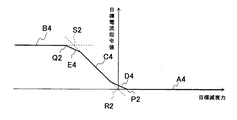
上記マップ演算に使用するマップは、2つあり、具体的には、緩衝器2が伸長作動する場合に使用される収縮側マップM3と、緩衝器2が収縮作動する場合に使用される伸長側マップM4がある。つまり、マップは、緩衝器2の伸縮方向毎に用意されている。収縮側マップM3は、図13に示すように、緩衝器2が収縮しており目標減衰力が緩衝器2に収縮方向の減衰力の発生を指示している場合に対応して目標減衰力の変化に対して一定値をとる出力下限ラインA3と、緩衝器2が収縮しており目標減衰力が緩衝器2に伸長方向の減衰力の発生を指示しているが出力上限を上回る場合に対応して目標減衰力の変化に対して一定値をとる出力上限ラインB3と、出力下限ラインA3と出力上限ラインB3とを結ぶとともに、緩衝器2が収縮しており目標減衰力が緩衝器2に伸長方向の減衰力の発生を指示しており出力可能範囲にある場合に対応して目標減衰力に対して比例的に変化する出力可能ラインC3と、出力可能ラインC3と出力下限ラインA3との間を接続する緩和ラインD3と、出力可能ラインC3と出力上限ラインB3との間を接続する緩和ラインE3とを備えている。対して、伸長側マップM4は、図14に示すように、緩衝器2が伸長しており目標減衰力が緩衝器2に伸長方向の減衰力の発生を指示している場合に対応して目標減衰力の変化に対して一定値をとる出力下限ラインA4と、緩衝器2が伸長しており目標減衰力が緩衝器2に収縮方向の減衰力の発生を指示しているが出力上限を上回る場合に対応して目標減衰力の変化に対して一定値をとる出力上限ラインB4と、出力下限ラインA4と出力上限ラインB4とを結ぶとともに、緩衝器2が伸長しており目標減衰力が緩衝器2に収縮方向の減衰力の発生を指示しており出力可能範囲にある場合に対応して目標減衰力に対して比例的に変化する出力可能ラインC4と、出力可能ラインC4と出力下限ラインA4との間を接続する緩和ラインD4と、出力可能ラインC4と出力上限ラインB4との間を接続する緩和ラインE4とを備えている。なお、収縮側マップM3および伸長側マップM4において、目標減衰力は緩衝器2に伸長方向に減衰力を発生させる値を正とし、つまり、収縮を妨げる減衰力を緩衝器2に発揮させる目標減衰力の値を正としてあり、反対方向の減衰力を発生させる目標減衰力を負としている。この実施の形態で目標電流指令
値が目標減衰力の方向の如何によらず、0以上の値となるのは、減衰力調整機構3への電流供給によって減衰係数を調節しているからである。なお、上記したところでは、目標減衰力が緩衝器2の出力可能範囲にある場合、減衰力調整機構3へ与える電流と緩衝器2の発生減衰力が比例関係にあるので、上記収縮側マップM1および伸長側マップM2において出力可能ラインC1,C2は、目標電流指令値が電流値目標減衰力に応じて比例的に変化するので直線となるが、緩衝器2の発生減衰力と電流との関係が非線形である場合には、出力可能ラインC1,C2も発生減衰力と電流との関係に即したものとされればよい。つまり、緩衝器2の発生減衰力と電流との関係を示す線が途中で屈曲点を持っているのであれば、出力可能ラインC1,C2も途中に屈曲点を持つ折れ線で示され、緩衝器2の発生減衰力と電流との関係を示す線が曲線であれば、出力可能ラインC1,C2も曲線で示されることになる。
There are two maps used for the map calculation. Specifically, the contraction side map M3 used when the shock absorber 2 operates to expand and the expansion side used when the shock absorber 2 operates to contract. There is a map M4. That is, a map is prepared for each expansion / contraction direction of the shock absorber 2. As shown in FIG. 13, the contraction-side map M3 corresponds to the case where the shock absorber 2 is contracting and the target damping force instructs the shock absorber 2 to generate a damping force in the contracting direction. Corresponding to the output lower limit line A3 that takes a constant value with respect to the change, and when the shock absorber 2 is contracted and the target damping force instructs the shock absorber 2 to generate a damping force in the extension direction, but exceeds the output upper limit. The output upper limit line B3 that takes a constant value with respect to the change in the target damping force, the output lower limit line A3, and the output upper limit line B3 are connected, and the shock absorber 2 is contracted, so that the target damping force is applied to the shock absorber 2. Corresponding to the case where the generation of the damping force in the extending direction is instructed and within the output possible range, the output possible line C3 that changes in proportion to the target damping force, the output possible line C3, and the output lower limit line A3 Mitigation line D3 connecting the two and output possible And a relaxation line E3 connecting the in-C3 and the output upper limit line B3. On the other hand, as shown in FIG. 14, the extension side map M4 corresponds to a case where the shock absorber 2 is extended and the target damping force instructs the shock absorber 2 to generate a damping force in the extension direction. The output lower limit line A4 that takes a constant value with respect to the change of the damping force, and the shock absorber 2 is extended, and the target damping force instructs the shock absorber 2 to generate the damping force in the contraction direction, but exceeds the output upper limit. Corresponding to the case, the output upper limit line B4 that takes a constant value with respect to the change of the target damping force, the output lower limit line A4, and the output upper limit line B4 are connected, and the shock absorber 2 is extended so that the target damping force is buffered. The output possible line C4 which changes in proportion to the target damping force corresponding to the case where the generator 2 is instructed to generate the damping force in the contraction direction and is within the output possible range, the output possible line C4 and the output lower limit line A relaxation line D4 connecting between A4 and A4; And a relaxation line E4 which connects between the force possible line C4 and the output limit line B4. In the contraction side map M3 and the expansion side map M4, the target damping force is a positive value that causes the shock absorber 2 to generate a damping force in the expansion direction, that is, the target damping force that causes the shock absorber 2 to exert a damping force that prevents contraction. The force value is positive, and the target damping force that generates damping force in the opposite direction is negative. In this embodiment, the target current command value is 0 or more regardless of the direction of the target damping force because the damping coefficient is adjusted by supplying current to the damping force adjusting mechanism 3. . In the above description, when the target damping force is within the output possible range of the shock absorber 2, the current applied to the damping force adjusting mechanism 3 and the generated damping force of the shock absorber 2 are in a proportional relationship. The output possible lines C1 and C2 in the expansion side map M2 are linear because the target current command value changes proportionally according to the current value target damping force, but the relationship between the generated damping force of the shock absorber 2 and the current Is non-linear, the output possible lines C1 and C2 may be set in accordance with the relationship between the generated damping force and the current. That is, if the line indicating the relationship between the generated damping force of the shock absorber 2 and the current has a bending point in the middle, the output possible lines C1 and C2 are also indicated by broken lines having a bending point in the middle. If the line indicating the relationship between the generated damping force 2 and the current is a curve, the output possible lines C1 and C2 are also indicated by the curve.

ここで、緩衝器2は、パッシブな緩衝器であり、自発的に推力を発生することができないので、目標減衰力の方向が緩衝器2の伸縮方向と同じ方向である場合、緩衝器2は目標減衰力の方向と同方向へ減衰力を発揮することができないため、緩衝器2の発生減衰力を限りなく小さくする必要がある。そのため、緩衝器2の減衰力を最小とすべく、この実施の形態では目標電流指令値を0とする。すなわち、出力下限ラインA3,A4は、この場合、0で一定となる。   Here, since the shock absorber 2 is a passive shock absorber and cannot generate a thrust spontaneously, when the direction of the target damping force is the same direction as the expansion and contraction direction of the shock absorber 2, the shock absorber 2 is Since the damping force cannot be exhibited in the same direction as the target damping force, it is necessary to reduce the damping force generated by the shock absorber 2 as much as possible. Therefore, in order to minimize the damping force of the shock absorber 2, the target current command value is set to 0 in this embodiment. That is, the output lower limit lines A3 and A4 are constant at 0 in this case.

また、目標減衰力の方向が緩衝器2の伸縮方向と逆方向である場合であって、緩衝器2の減衰力の出力上限を上回る場合、緩衝器2の発生減衰力を目標減衰力に追随させることができないが、緩衝器2の発生減衰力を限りなく目標減衰力に近づけるため、緩衝器2の減衰力を最大とすべく、この実施の形態では目標電流指令値を所定の上限値とする。すなわち、出力上限ラインB3,B4は、この場合、ハードウェア上の電流値の上限値で一定となる。   Further, when the direction of the target damping force is opposite to the expansion / contraction direction of the shock absorber 2 and exceeds the upper limit of the damping force output of the shock absorber 2, the generated damping force of the shock absorber 2 follows the target damping force. However, in order to maximize the damping force of the shock absorber 2, the target current command value is set to a predetermined upper limit value in order to maximize the damping force of the shock absorber 2. To do. That is, in this case, the output upper limit lines B3 and B4 are constant at the upper limit value of the current value on the hardware.

そして、目標減衰力の方向が緩衝器2の伸縮方向と逆方向である場合であって、目標減衰力が緩衝器2の出力可能な範囲である場合には、上述したように目標減衰力に対して目標電流指令値が一対一の関係となり、目標減衰力に対して目標電流指令値が比例することになり、出力可能ラインC3,C4は、目標減衰力に対してある傾きをもって比例する。この出力可能ラインC3,C4の傾きは、目標減衰力軸に対する傾きは一定で、減衰力調整機構3への供給電流量と緩衝器2における減衰力との関係に依存して決定される。   When the direction of the target damping force is opposite to the expansion / contraction direction of the shock absorber 2 and the target damping force is within the output range of the shock absorber 2, the target damping force is set to the target damping force as described above. On the other hand, the target current command value has a one-to-one relationship, the target current command value is proportional to the target damping force, and the output possible lines C3 and C4 are proportional to the target damping force with a certain inclination. The inclinations of the output possible lines C3 and C4 are determined depending on the relationship between the amount of current supplied to the damping force adjusting mechanism 3 and the damping force in the shock absorber 2 while the slope with respect to the target damping force axis is constant.

なお、電気粘性流体を用いた緩衝器の場合、収縮側マップM3と伸長側マップM4における縦軸を目標電圧指令値とし、制御装置4は、目標減衰力から目標電圧指令値を求めるようにすればよい。また、減衰力調整機構3が電磁弁であって電流供給を行わない場合に緩衝器2が最大減衰力を発生する場合には、出力下限ラインA3,A4をハードウェア上の電流値の上限値で一定とし、出力上限ラインB3,B4を0で一定とするようなマップとすればよい。   In the case of a shock absorber using an electrorheological fluid, the vertical axis in the contraction side map M3 and the expansion side map M4 is the target voltage command value, and the control device 4 is configured to obtain the target voltage command value from the target damping force. That's fine. Further, when the damping force adjusting mechanism 3 is a solenoid valve and the shock absorber 2 generates the maximum damping force when no current is supplied, the output lower limit lines A3 and A4 are set to the upper limit value of the current value on the hardware. And the output upper limit lines B3 and B4 may be constant at 0.

たとえば、減衰力調整機構3のコイル26をPWM制御する場合には、目標電流指令値を供給電流値と一対一の関係となるデューティ比として求め、コイル26にPWMパルス電圧を印加するドライバ43へデューティ比でなる目標電流指令値を与えるようにして、減衰力調整機構3への供給電流を制御するようにしてもよい。また、ドライバは、制御装置4側に設けるのではなく、減衰力調整機構3側に設けるようにしてもよい。さらに、目標電流指令値は、減衰力調整機構3へ供給する電流値そのものとしてもよい。   For example, when the coil 26 of the damping force adjusting mechanism 3 is subjected to PWM control, the target current command value is obtained as a duty ratio that has a one-to-one relationship with the supply current value, and is supplied to the driver 43 that applies the PWM pulse voltage to the coil 26. The supply current to the damping force adjusting mechanism 3 may be controlled by giving a target current command value that is a duty ratio. Further, the driver may be provided on the damping force adjusting mechanism 3 side instead of being provided on the control device 4 side. Further, the target current command value may be the current value itself supplied to the damping force adjusting mechanism 3.

そして、収縮側マップM3において、緩和ラインD3は、出力下限ラインA3に対して、出力可能ラインC3より傾きを小さくして接続されており、出力可能ラインC3が出力下限ラインA3に対して図13中破線で示すように直接傾きを変えずに接続される場合に比較して、出力下限ラインA3との交点P1を跨いでの目標電流指令値の変化が緩和されることになる。また、収縮側マップM3において、緩和ラインE3は、出力上限ラインB3に対して、出力可能ラインC3より傾きを小さくして接続されており、出力可能ラインC3が出力上限ラインB3に対して図13中破線で示すように直接傾きを変えずに接続される場合に比較して、出力上限ラインB3との交点Q1を跨いでの目標電流指令値の変化が緩和されることになる。   In the contraction side map M3, the relaxation line D3 is connected to the output lower limit line A3 with a smaller slope than the output possible line C3, and the output possible line C3 is connected to the output lower limit line A3 in FIG. As shown by the middle broken line, the change in the target current command value across the intersection P1 with the output lower limit line A3 is alleviated as compared with the case where the connection is made without changing the inclination directly. In the contraction side map M3, the relaxation line E3 is connected to the output upper limit line B3 with a smaller slope than the output possible line C3, and the output possible line C3 is connected to the output upper limit line B3 in FIG. As shown by the middle broken line, the change in the target current command value across the intersection Q1 with the output upper limit line B3 is alleviated as compared with the case where the connection is made without changing the inclination directly.

さらに、伸長側マップM4においても、緩和ラインD4は、出力下限ラインA4に対して、出力可能ラインC4より傾きを小さくして接続されており、出力可能ラインC2が出力下限ラインA4に対して図14中破線で示すように直接傾きを変えずに接続される場合に比較して、出力下限ラインA4との交点P2を跨いでの目標電流指令値の変化が緩和されることになる。また、伸長側マップM4においても、緩和ラインE4は、出力上限ラインB4に対して、出力可能ラインC4より傾きを小さくして接続されており、出力可能ラインC4が出力上限ラインB4に対して図14中破線で示すように直接傾きを変えずに接続される場合に比較して、出力上限ラインB4との交点Q2を跨いでの目標電流指令値の変化が緩和されることになる。   Further, also in the expansion side map M4, the relaxation line D4 is connected to the output lower limit line A4 with a smaller slope than the output possible line C4, and the output possible line C2 is connected to the output lower limit line A4. Compared with the case where the connection is made without changing the inclination directly as shown by the broken line in FIG. 14, the change in the target current command value across the intersection P2 with the output lower limit line A4 is alleviated. Also in the expansion side map M4, the relaxation line E4 is connected to the output upper limit line B4 with a smaller slope than the output possible line C4, and the output possible line C4 is connected to the output upper limit line B4. Compared with the case where the connection is made without changing the inclination directly as shown by the broken line in FIG. 14, the change in the target current command value across the intersection Q2 with the output upper limit line B4 is alleviated.

このように、目標減衰力から減衰力調整機構3へ供給する電流量を決する目標電流指令値を求める収縮側マップM3および伸長側マップM4にあっては、緩和ラインD3,D4,E3,E4が設けられているので、目標減衰力が緩衝器2の出力可能な減衰力の範囲(出力可能範囲)内から出力できない範囲(出力不能範囲)へ、或いは、出力不能範囲から出力可能範囲内へ変化する場合に、目標電流指令値の変化量が緩和されるので、緩衝器2が発生する減衰力の急変を抑制でき、車体振動を効果的に制振して、車両における乗り心地を向上することができる。すなわち、他の実施の形態におけるサスペンション装置では、目標減衰力を補正することによって、緩衝器2の伸縮速度に対する緩衝器2の減衰力の急変を緩和することができるだけでなく、目標減衰力の変化に対する減衰力の急変を緩和することができるのである。   Thus, in the contraction side map M3 and the expansion side map M4 for obtaining the target current command value for determining the amount of current to be supplied from the target damping force to the damping force adjusting mechanism 3, the relaxation lines D3, D4, E3, E4 are Because it is provided, the target damping force changes from the damping force output range (output possible range) of the shock absorber 2 to the range where output is impossible (output impossible range), or from the output impossible range to output possible range. In this case, since the amount of change in the target current command value is alleviated, a sudden change in the damping force generated by the shock absorber 2 can be suppressed, and the vehicle vibration can be effectively suppressed to improve the riding comfort in the vehicle. Can do. That is, in the suspension device according to another embodiment, by correcting the target damping force, not only can the sudden change in the damping force of the shock absorber 2 with respect to the expansion / contraction speed of the shock absorber 2 be reduced, but also the change in the target damping force. It is possible to mitigate sudden changes in the damping force with respect to.

なお、緩和ラインD3,D4,E3,E4は、上記したところでは、一定の傾きをもった直線とされているが、徐々に傾きが変化して、出力可能ラインC3,C4、出力下限ラインA3,A4および出力上限ラインB3,B4へ滑らか接続するようにしてもよい。すなわち、緩和ラインD3,D4,E3,E4は、出力可能ラインC3,C4の傾きから徐々に傾きが小さくなって出力下限ラインA3,A4および出力上限ラインB3,B4へ滑らか接続する円弧状のラインとされてもよい。また、緩和ラインD3と緩和ラインE3の傾きや形状、長さは、ともに同じであるが異なるように設定されてもよいし、緩和ラインD4と緩和ラインE4の傾き、形状および長さについても同様に異なっていてもよい。さらに、収縮側マップM3と伸長側マップM4におけるライン形状(出力下限ラインA3,A4、出力上限ラインB3,B4、出力可能ラインC3,D4および緩和ラインD3,D4,E3,E4を繋いだ形状)は、目標電流指令値軸を中心として線対称の形状となっているが、これに限られるものではない。   Although the relaxation lines D3, D4, E3, and E4 are straight lines having a certain slope as described above, the slope gradually changes, and the output possible lines C3 and C4 and the output lower limit line A3. , A4 and the output upper limit lines B3, B4 may be smoothly connected. In other words, the relaxation lines D3, D4, E3, and E4 are arc-shaped lines that gradually decrease from the inclination of the output possible lines C3 and C4 and smoothly connect to the output lower limit lines A3 and A4 and the output upper limit lines B3 and B4. It may be said. In addition, the inclination, shape, and length of the relaxation line D3 and the relaxation line E3 are both the same, but may be set to be different. The same applies to the inclination, shape, and length of the relaxation line D4 and the relaxation line E4. May be different. Further, the line shape in the contraction side map M3 and the expansion side map M4 (shape connecting the output lower limit lines A3, A4, the output upper limit lines B3, B4, the output possible lines C3, D4 and the relaxation lines D3, D4, E3, E4) Is a line-symmetric shape with respect to the target current command value axis, but is not limited to this.

また、この例では、収縮側マップM3と伸長側マップM4を持っているが、伸長側と収縮側で減衰特性が同じであれば、マップを一つにしておき、目標減衰力の絶対値に対して目標電流指令値或いは目標電圧指令値を求めるようにしてもよい。   Further, in this example, the contraction side map M3 and the expansion side map M4 are provided. However, if the attenuation characteristics are the same on the expansion side and the contraction side, the maps are made one and the absolute value of the target damping force is obtained. On the other hand, a target current command value or a target voltage command value may be obtained.

さらに、上記したところでは、減衰力調整機構3へ与える電流量によって緩衝器2の減衰係数が変化する特性となっており、目標減衰力を上記必要減衰力から最低減衰力を減じて求めるようにしているので、収縮側マップM3と伸長側マップM4を持っていればよく、マップ演算も簡単となるが、目標減衰力を上記で言うところの必要減衰力として目標電流指令値或いは目標電圧指令値を求める場合には、緩衝器2の伸縮速度に応じて目標減衰力と目標電流指令値或いは目標電圧指令値との関係が決定される三次元マップを用いて求めるようにしてもよいし、複数の緩衝器2の伸縮速度に対して作成した目標減衰力と目標電流指令値或いは目標電圧指令値のマップを保有して、緩衝器2の伸縮速度に応じてマップ間を補完することで目標電流指令値或いは目標電圧指令値を求めるようにしてもよい。   Further, in the above description, the damping coefficient of the shock absorber 2 changes depending on the amount of current applied to the damping force adjusting mechanism 3, and the target damping force is obtained by subtracting the minimum damping force from the required damping force. Therefore, it is only necessary to have the contraction side map M3 and the expansion side map M4, and the map calculation is simplified. However, the target damping force is the target current command value or the target voltage command value as the necessary damping force as described above. May be obtained using a three-dimensional map in which the relationship between the target damping force and the target current command value or the target voltage command value is determined in accordance with the expansion / contraction speed of the shock absorber 2. A map of the target damping force and the target current command value or target voltage command value created for the expansion / contraction speed of the shock absorber 2 is retained, and the target current is complemented between the maps according to the expansion / contraction speed of the shock absorber 2 It may be obtained decree value or target voltage command value.

ところで、緩和ラインD3,D4は、出力可能ラインC3,C4よりも傾きが小さいので、出力可能ラインC3,C4が傾きを変えずに出力下限ラインA3,A4と交わる仮想交点R1,R2に緩和ラインD3,D4を接続すると、出力可能ラインC3,C4と交わらなくなるので、仮想交点R1,R2よりも線分が上方にある。つまり、緩和ラインD3,D4を設けると、目標減衰力が0であるときに目標電流指令値が或る正の値をとることになる。   By the way, the relaxation lines D3 and D4 are smaller in inclination than the output possible lines C3 and C4, so that the output possible lines C3 and C4 do not change the inclination, and the relaxation lines are at the virtual intersections R1 and R2 that intersect the output lower limit lines A3 and A4. When D3 and D4 are connected, they do not intersect with the output possible lines C3 and C4, so the line segment is above the virtual intersections R1 and R2. That is, when the relaxation lines D3 and D4 are provided, the target current command value takes a certain positive value when the target damping force is zero.

このうち、緩和ラインD3,D4では、目標減衰力が0の近傍であって目標減衰力の方向と緩衝器2の伸縮方向が異なる場合には、目標電流指令値が正の値をとることになるので、緩衝器2が僅かであるが減衰力を出力することになる。この減衰力が乗り心地に与える影響が無視できない場合、緩和ラインD3,D4を廃止するようにしてもよい。また、緩和ラインD3,D4を設けておいて、目標減衰力から目標電流指令値を求めた後に、緩衝器2の伸縮速度が緩和ラインD3,D4の影響する速度以内では0の値をとるゲインを乗じて、目標減衰力が0の近傍であるときの緩和ラインD3,D4が乗り心地に与える影響を取り除くようにしてもよい。なお、ゲインを用いる場合は、緩和ラインD3,D4を廃しするのではなく、乗り心地の悪化を及ぼす部分についてのみ、緩和ラインD3,D4の影響を排除すればよいので、緩和ラインD3,D4を設けることによる上記利点を生かしながら乗り心地の悪化を招くことを防止することができる。ゲインの設け方としては、たとえば、緩衝器2の伸縮速度によって緩和ラインD3,D4を効かせたくない範囲におけるゲインを0とし、そうでない範囲を1に設定すればよいが、図15に示すように、ゲインを0から急に1へステップ的に変化させるのではなく、ランプ的に徐々に変化させるようにしてもよい。ランプ的に変化させることで、緩衝器2の減衰力変化を滑らかにすることができる。なお、減衰力調整機構3が電磁弁であって電流供給を行わない場合に緩衝器2が最大減衰力を発生する場合には、出力上限ラインB3,B4に接続される緩和ラインE3,E4の影響を取り除くようにすればよい。   Among these, in the relaxation lines D3 and D4, when the target damping force is in the vicinity of 0 and the direction of the target damping force and the expansion / contraction direction of the shock absorber 2 are different, the target current command value takes a positive value. Therefore, the shock absorber 2 outputs a damping force although it is small. If the influence of the damping force on the riding comfort cannot be ignored, the relaxation lines D3 and D4 may be eliminated. Further, after providing the relaxation lines D3 and D4 and obtaining the target current command value from the target damping force, the gain that takes a value of 0 when the expansion / contraction speed of the shock absorber 2 is within the speed affected by the relaxation lines D3 and D4. To reduce the influence of the relaxation lines D3 and D4 on the riding comfort when the target damping force is in the vicinity of zero. In the case of using the gain, the relaxation lines D3 and D4 need not be eliminated, but the influence of the relaxation lines D3 and D4 may be eliminated only for the portion that causes the deterioration of the ride comfort. It is possible to prevent the ride comfort from deteriorating while taking advantage of the above-described advantages. As a method of providing the gain, for example, the gain in the range where the relaxation lines D3 and D4 are not desired to be applied depending on the expansion / contraction speed of the shock absorber 2 may be set to 0, and the other range may be set to 1, as shown in FIG. In addition, the gain may be gradually changed in a ramp manner instead of stepwise from 0 to 1. The change in the damping force of the shock absorber 2 can be smoothed by changing the ramp. In the case where the damping force adjusting mechanism 3 is a solenoid valve and the shock absorber 2 generates the maximum damping force when no current is supplied, the relaxation lines E3 and E4 connected to the output upper limit lines B3 and B4 The influence should be removed.

なお、他の実施の形態のサスペンション装置にあっても、上記した一実施の形態におけるサスペンション装置1と同様にリミッタ42を省略することも可能であるが、リミッタ42を設ける場合、目標減衰力を制限する制限値の値を緩和ラインD3,D4が出力上限ラインB3,B4に接続する交点における目標減衰力に設定する。緩和ラインE3,E4を設けることにより、図13および図14に示すように、目標電流指令値が最大となるのは目標減衰力が緩衝器2のハードウェア上の最大減衰力を超えた値となるので、リミッタ42の制限値を目標電流指令値が最大となる目標減衰力とすればよいことになる。   Even in the suspension device according to another embodiment, the limiter 42 can be omitted as in the suspension device 1 according to the above-described one embodiment. However, when the limiter 42 is provided, the target damping force is reduced. The limit value to be limited is set to the target damping force at the intersection where the relaxation lines D3 and D4 connect to the output upper limit lines B3 and B4. By providing the relaxation lines E3 and E4, as shown in FIGS. 13 and 14, the target current command value is maximized when the target damping force exceeds the maximum damping force on the hardware of the shock absorber 2. Therefore, the limit value of the limiter 42 may be a target damping force that maximizes the target current command value.

このようにすれば、他の実施の形態におけるサスペンション装置にあっても、一実施の形態におけるサスペンション装置1と同様に、リミッタ42の設置によって、目標減衰力を制限してから補正部43にて補正するようにすれば、補正後の目標減衰力は緩衝器2の発生可能減衰力範囲内にほぼ収まり、緩衝器2の伸縮速度が所定速度Vp1および速度閾値Vp2における緩衝器2の発生減衰力の変化をほぼ確実に緩和することができる。 In this way, even in the suspension device according to another embodiment, as in the suspension device 1 according to one embodiment, the limiter 42 is installed to limit the target damping force, and then the correction unit 43 If the correction is made, the corrected target damping force is almost within the range of the damping force that can be generated by the shock absorber 2, and the shock absorber 2 generates at the predetermined speed V p1 and the speed threshold V p2 when the expansion / contraction speed of the shock absorber 2 is the predetermined speed V p1. The change of the damping force can be moderated with certainty.

以上で、本発明の実施の形態についての説明を終えるが、本発明の範囲は図示されまたは説明された詳細そのものには限定されないことは勿論である。   This is the end of the description of the embodiment of the present invention, but the scope of the present invention is of course not limited to the details shown or described.

本発明の車両用緩衝器は、車両の制振用途に利用することができる。   The vehicular shock absorber of the present invention can be used for vibration control of a vehicle.

1 サスペンション装置
2 緩衝器
20 シリンダ
21 ピストン
22 ピストンロッド
23,24 圧力室
25 通路
26 コイル
3 減衰力調整機構
4 制御装置
41 目標減衰力演算部
42 リミッタ
43 補正部
44 目標電流指令値演算部
45 ドライバ
5 加速度センサ
6 ストロークセンサ
A1,A2,A3,A4 出力下限ライン
B1,B2,B3,B4 出力上限ライン
C1,C2,C3,C4 出力可能ライン
D3,D4,E3,E4 緩和ライン
M1,M3 収縮側マップ
M2,M4 伸長側マップ
DESCRIPTION OF SYMBOLS 1 Suspension apparatus 2 Shock absorber 20 Cylinder 21 Piston 22 Piston rods 23 and 24 Pressure chamber 25 Passage 26 Coil 3 Damping force adjustment mechanism 4 Control device 41 Target damping force calculation part 42 Limiter 43 Correction part 44 Target current command value calculation part 45 Driver 5 Acceleration sensor 6 Stroke sensor A1, A2, A3, A4 Output lower limit line B1, B2, B3, B4 Output upper limit line C1, C2, C3, C4 Output possible line D3, D4, E3, E4 Relaxation line M1, M3 Contraction side Map M2, M4 Expansion side map

Claims (6)

車両における車体と車輪との間に介装されて車体と車輪との上下方向の相対移動を抑制する減衰力を発揮する緩衝器と、減衰力を調節する減衰力調整機構と、目標減衰力に基づいて当該減衰力調整機構を制御する制御装置とを備えたサスペンション装置において、上記制御装置は、上記緩衝器の伸縮速度が0および所定速度における緩衝器の発生減衰力の変化を緩和する補正手段を備え、当該補正手段は、緩衝器の伸縮速度が上記所定速度を超える値に設定される速度閾値を超えると当該伸縮速度が0となるまでは、発生減衰力変化を緩和する伸縮速度を上記速度閾値と上記所定速度の差分だけ速度増側へオフセットして発生減衰力を補正するとともに上記差分から伸縮速度が0までは発生減衰力を最小とするよう補正することを特徴とするサスペンション装置。 A shock absorber that is interposed between the vehicle body and the wheel in the vehicle to suppress the relative movement of the vehicle body and the wheel in the vertical direction, a damping force adjustment mechanism that adjusts the damping force, and a target damping force And a control device for controlling the damping force adjusting mechanism based on the control device, wherein the control device relaxes a change in the damping force generated by the shock absorber when the expansion speed of the shock absorber is zero and a predetermined speed. And the correction means sets the expansion / contraction speed for relaxing the generated damping force change until the expansion / contraction speed becomes zero when the expansion / contraction speed of the shock absorber exceeds a speed threshold set to a value exceeding the predetermined speed. The generated damping force is corrected by offsetting toward the speed increasing side by the difference between the speed threshold and the predetermined speed, and the generated damping force is corrected to be minimized until the expansion / contraction speed is zero from the difference. Scan pension system. 上記補正手段は、上記緩衝器の伸縮速度から求めた補正係数を上記減衰力調整機構へ与える指令に乗じて発生減衰力を補正することを特徴とする請求項1に記載のサスペンション装置。 2. The suspension apparatus according to claim 1, wherein the correction means corrects the generated damping force by multiplying a command given to the damping force adjusting mechanism by a correction coefficient obtained from the expansion / contraction speed of the shock absorber. 上記所定速度をVp1とし、上記速度閾値をVp2とし、当該速度閾値から上記所定速度を差し引きした速度閾値と所定速度の差分をβとし、上記緩衝器の伸縮速度をxとすると、上記補正手段は、x>Vp2を満たさずx≦Vp1の場合、0≦x≦Vp1/2の場合と、Vp1/2<x≦Vp1の場合に分けて、それぞれに対応する二次関数を用いて補正係数を演算し、x>Vp2を満たすと0になるまでは、β≦x≦Vp2−Vp1/2の場合と、Vp2−Vp1/2<x≦Vp2の場合に分けて、それぞれに対応する二次関数を用いて補正係数を演算するとともに0≦x<βのおける補正係数を0とすることを特徴とする請求項1または2に記載のサスペンション装置。 When the predetermined speed is V p1 , the speed threshold is V p2 , the difference between the speed threshold obtained by subtracting the predetermined speed from the speed threshold and the predetermined speed is β, and the expansion / contraction speed of the shock absorber is x, the correction The means does not satisfy x> V p2 , x ≦ V p1 , 0 ≦ x ≦ V p1 / 2 and V p1 / 2 <x ≦ V p1. When a correction coefficient is calculated using a function and x> V p2 is satisfied, until 0 is satisfied, β ≦ x ≦ V p2 −V p1 / 2 and V p2 −V p1 / 2 <x ≦ V p2 The suspension apparatus according to claim 1 or 2, wherein the correction coefficient is calculated using a quadratic function corresponding to each of the cases, and the correction coefficient in 0 ≦ x <β is set to 0. . 上記所定速度をVp1とし、上記速度閾値をVp2とし、当該速度閾値から上記所定速度を差し引きした速度閾値と所定速度の差分をβとし、上記緩衝器の伸縮速度をxとすると、上記補正手段は、x>Vp2を満たさずx≦Vp1の場合、0≦x≦Vp1/2の場合には、補正係数αをα=2x/Vp1 を演算して求め、Vp1/2<x≦Vp1の場合には、補正係数αをα=−2(x−Vp1/Vp1 +1を演算して求め、x>Vp2を満たすと0になるまでは、β≦x≦Vp2−Vp1/2の場合には、補正係数αをα=2(x−β)/Vp1 を演算して求め、Vp2−Vp1/2<x≦Vp2の場合には、補正係数αをα=−2(x−β−Vp1/Vp1 +1を演算して求めるとともに0≦x<βのおける補正係数を0とすることを特徴とする請求項1から3のいずれか一項に記載のサスペンション装置。 When the predetermined speed is V p1 , the speed threshold is V p2 , the difference between the speed threshold obtained by subtracting the predetermined speed from the speed threshold and the predetermined speed is β, and the expansion / contraction speed of the shock absorber is x, the correction means, in the case of x ≦ V p1 not satisfy the x> V p2, 0 in the case of ≦ x ≦ V p1 / 2 is determined by calculating the correction coefficient α α = 2x 2 / V p1 2, V p1 / 2 <x ≦ V p1 , the correction coefficient α is calculated by calculating α = −2 (x−V p1 ) 2 / V p1 2 +1 until x> V p2 is satisfied until 0 is satisfied. , Β ≦ x ≦ V p2 −V p1 / 2, the correction coefficient α is obtained by calculating α = 2 (x−β) 2 / V p1 2 , and V p2 −V p1 / 2 <x ≦ 0 with the case of V p2 obtains a correction coefficient α α = -2 (x-β -V p1) by calculating a 2 / V p1 2 +1 The suspension device according to any one of claims 1 to 3, the definitive correction coefficient of x <beta characterized by zero. 上記制御装置は、上記指令を制限値にクランプするリミッタ処理を行うリミッタ手段を備え、当該指令のリミッタ処理を行ってから補正係数を演算するとともに、補正手段は、リミッタ処理後の上記指令を補正することを特徴とする請求項1から4のいずれか一項に記載のサスペンション装置。 The control device includes a limiter unit that performs a limiter process that clamps the command to a limit value, calculates a correction coefficient after performing the limiter process of the command, and the correction unit corrects the command after the limiter process. The suspension device according to any one of claims 1 to 4, wherein 上記所定速度および速度閾値は、上記制御装置で求める目標減衰力に応じて変化することを特徴とする請求項1から5のいずれか一項に記載のサスペンション装置。 The suspension device according to any one of claims 1 to 5, wherein the predetermined speed and the speed threshold value change according to a target damping force obtained by the control device.
JP2011010643A 2011-01-21 2011-01-21 Suspension device Active JP5603787B2 (en)

Priority Applications (1)

Application Number Priority Date Filing Date Title
JP2011010643A JP5603787B2 (en) 2011-01-21 2011-01-21 Suspension device

Applications Claiming Priority (1)

Application Number Priority Date Filing Date Title
JP2011010643A JP5603787B2 (en) 2011-01-21 2011-01-21 Suspension device

Publications (2)

Publication Number Publication Date
JP2012148734A true JP2012148734A (en) 2012-08-09
JP5603787B2 JP5603787B2 (en) 2014-10-08

Family

ID=46791438

Family Applications (1)

Application Number Title Priority Date Filing Date
JP2011010643A Active JP5603787B2 (en) 2011-01-21 2011-01-21 Suspension device

Country Status (1)

Country Link
JP (1) JP5603787B2 (en)

Cited By (3)

* Cited by examiner, † Cited by third party
Publication number Priority date Publication date Assignee Title
WO2015068711A1 (en) * 2013-11-08 2015-05-14 カヤバ工業株式会社 Shock absorber device
JP2020132122A (en) * 2019-02-26 2020-08-31 日立オートモティブシステムズ株式会社 Suspension device and method of controlling the same
JP6789443B1 (en) * 2020-03-17 2020-11-25 株式会社ショーワ Control device, suspension system, saddle-mounted vehicle

Citations (4)

* Cited by examiner, † Cited by third party
Publication number Priority date Publication date Assignee Title
JPH01126804U (en) * 1988-02-25 1989-08-30
JPH0699717A (en) * 1992-09-17 1994-04-12 Nippondenso Co Ltd Damping force-changeable shock absorber control device
JPH06106945A (en) * 1992-09-24 1994-04-19 Nippondenso Co Ltd Damping force variable shock absorber control device
JP2010052488A (en) * 2008-08-26 2010-03-11 Hitachi Automotive Systems Ltd Suspension control device

Patent Citations (4)

* Cited by examiner, † Cited by third party
Publication number Priority date Publication date Assignee Title
JPH01126804U (en) * 1988-02-25 1989-08-30
JPH0699717A (en) * 1992-09-17 1994-04-12 Nippondenso Co Ltd Damping force-changeable shock absorber control device
JPH06106945A (en) * 1992-09-24 1994-04-19 Nippondenso Co Ltd Damping force variable shock absorber control device
JP2010052488A (en) * 2008-08-26 2010-03-11 Hitachi Automotive Systems Ltd Suspension control device

Cited By (7)

* Cited by examiner, † Cited by third party
Publication number Priority date Publication date Assignee Title
WO2015068711A1 (en) * 2013-11-08 2015-05-14 カヤバ工業株式会社 Shock absorber device
JP2015094365A (en) * 2013-11-08 2015-05-18 カヤバ工業株式会社 Shock absorber
CN105683611A (en) * 2013-11-08 2016-06-15 Kyb株式会社 Shock absorber device
JP2020132122A (en) * 2019-02-26 2020-08-31 日立オートモティブシステムズ株式会社 Suspension device and method of controlling the same
JP7161958B2 (en) 2019-02-26 2022-10-27 日立Astemo株式会社 Suspension device and its control method
JP6789443B1 (en) * 2020-03-17 2020-11-25 株式会社ショーワ Control device, suspension system, saddle-mounted vehicle
WO2021186541A1 (en) * 2020-03-17 2021-09-23 日立 Astemo 株式会社 Control device, suspension system, and saddle-type vehicle

Also Published As

Publication number Publication date
JP5603787B2 (en) 2014-10-08

Similar Documents

Publication Publication Date Title
WO2017002620A1 (en) Suspension control apparatus
JP2018177050A (en) Electromagnetic suspension device
JP2008012960A (en) Control device of damper
JP2012101666A (en) Suspension system
US20080140285A1 (en) Control device for a variable damper
CN107303832A (en) Adjustable damping system for seat
JP2011173465A (en) Control device of damping force adjustable damper
JP5603787B2 (en) Suspension device
WO2016068104A1 (en) Damper control apparatus
CN113400882B (en) Electric suspension device
JP6240663B2 (en) Damper control device
JP5503511B2 (en) Suspension device
JP5608057B2 (en) Suspension device
JP5113882B2 (en) Damper control device
JP5452451B2 (en) Suspension device
JP6059564B2 (en) Damper speed detection device
US9718324B2 (en) Damper control device
JP5131682B2 (en) Control device for variable damping force damper
JP6313586B2 (en) Damper control device
JP5452450B2 (en) Suspension device
JP2014227128A (en) Suspension device for vehicle
JP5148679B2 (en) Control device and control method for damping force variable damper
JP4638534B2 (en) Control device and control method for damping force variable damper
JP7253516B2 (en) suspension system
JP6838785B2 (en) Suspension control device

Legal Events

Date Code Title Description
A621 Written request for application examination

Free format text: JAPANESE INTERMEDIATE CODE: A621

Effective date: 20130718

A977 Report on retrieval

Free format text: JAPANESE INTERMEDIATE CODE: A971007

Effective date: 20140123

A131 Notification of reasons for refusal

Free format text: JAPANESE INTERMEDIATE CODE: A131

Effective date: 20140423

A521 Request for written amendment filed

Free format text: JAPANESE INTERMEDIATE CODE: A523

Effective date: 20140618

TRDD Decision of grant or rejection written
A01 Written decision to grant a patent or to grant a registration (utility model)

Free format text: JAPANESE INTERMEDIATE CODE: A01

Effective date: 20140805

A61 First payment of annual fees (during grant procedure)

Free format text: JAPANESE INTERMEDIATE CODE: A61

Effective date: 20140822

R151 Written notification of patent or utility model registration

Ref document number: 5603787

Country of ref document: JP

Free format text: JAPANESE INTERMEDIATE CODE: R151

S533 Written request for registration of change of name

Free format text: JAPANESE INTERMEDIATE CODE: R313533

R350 Written notification of registration of transfer

Free format text: JAPANESE INTERMEDIATE CODE: R350

R250 Receipt of annual fees

Free format text: JAPANESE INTERMEDIATE CODE: R250

S533 Written request for registration of change of name

Free format text: JAPANESE INTERMEDIATE CODE: R313533

R350 Written notification of registration of transfer

Free format text: JAPANESE INTERMEDIATE CODE: R350