JP2012148207A - Filter automatic cleaning device, air cleaner using the same, and air cleaner with humidifying function - Google Patents
Filter automatic cleaning device, air cleaner using the same, and air cleaner with humidifying function Download PDFInfo
- Publication number
- JP2012148207A JP2012148207A JP2011006596A JP2011006596A JP2012148207A JP 2012148207 A JP2012148207 A JP 2012148207A JP 2011006596 A JP2011006596 A JP 2011006596A JP 2011006596 A JP2011006596 A JP 2011006596A JP 2012148207 A JP2012148207 A JP 2012148207A
- Authority
- JP
- Japan
- Prior art keywords
- cleaning
- filter
- air
- cleaning means
- automatic
- Prior art date
- Legal status (The legal status is an assumption and is not a legal conclusion. Google has not performed a legal analysis and makes no representation as to the accuracy of the status listed.)
- Granted
Links
Images


Abstract
Description
本発明は、空気を浄化することのできる空気清浄装置および空気を浄化しながら加湿することのできる加湿機能付空気清浄装置のフィルタの清掃に関する。 The present invention relates to an air purifier capable of purifying air and cleaning of a filter of an air purifier with a humidifying function capable of humidifying while purifying air.
一般的な空気清浄装置および加湿機能付き空気清浄装置において、空気清浄手段として空気中の粗じんやホコリを分離するプレフィルタと、細かな砂塵や菌などを分離する集じんフィルタを組み合わせたものが使用されている。このプレフィルタは集じんフィルタに粗じんやホコリが付着し細かな砂塵や菌などに対する集じん効果が損なわれないように前もってこれらを除去し保護するものであるが、それによりプレフィルタが目詰まりしてしまうため定期的に清掃する必要がある。この清掃作業を自動化させたものも考案されている。 In general air purifiers and air purifiers with a humidifying function, a combination of a pre-filter that separates coarse dust and dust in the air and a dust collection filter that separates fine dust and fungi as air cleaning means in use. This prefilter removes and protects the dust collection filter in advance so that the dust collection filter does not impair the dust collection effect against fine dust and dirt. Therefore, it is necessary to clean regularly. An automated version of this cleaning work has also been devised.
例えば、プレフィルタを清掃する清掃手段がプレフィルタ表面を掃引しながら往復し、粗じんやホコリを除去する自動清掃手段が知られている(例えば特許文献1参照)。 For example, an automatic cleaning unit is known in which a cleaning unit that cleans the prefilter reciprocates while sweeping the surface of the prefilter to remove coarse dust and dust (see, for example, Patent Document 1).
以下、その自動清掃手段について図9(a)および図9(b)を参照しながら説明する。図9(a)は従来の自動清掃手段の構成を示す概略正面図、図9(b)は同自動清掃手段の構成を示す概略断面図である。 The automatic cleaning means will be described below with reference to FIGS. 9 (a) and 9 (b). FIG. 9A is a schematic front view showing the configuration of a conventional automatic cleaning means, and FIG. 9B is a schematic sectional view showing the configuration of the automatic cleaning means.
図9(a)に示すように、自動清掃手段は、プレフィルタ101を清掃する回転ブラシ102を有する清掃ケース103と、回転ブラシ102を回転させる回転手段104と、回転手段104を内包し清掃ケース103を上下に往復移動させるための駆動手段105を備えている。
As shown in FIG. 9A, the automatic cleaning means includes a
また、図9(b)に示すように回転ブラシ102は、左右方向に延びる軸部材106と、軸部材106の表面に備えられた毛羽部107によって構成されており、軸部材106は清掃ケース103に回転可能に軸支されている。また、回転手段104と軸部材106とは連結されているので、回転手段104の運転により軸部材106が回転するようになっている。また、回転ブラシ102は、自身の回転により毛羽部107がプレフィルタ4の左右方向全面を摺動するような長さに構成されている。
Further, as shown in FIG. 9B, the rotating
次に、その動作について説明する。 Next, the operation will be described.
回転手段104を運転すると軸部材106が回転し、軸部材106に備えられた毛羽部107がプレフィルタ4表面を摺動する。この摺動によりプレフィルタ4に付着した粗じんやホコリをプレフィルタ4から掻き出して清掃を行う。そして、回転手段104の運転とともに駆動手段20の運転を行うことによって、清掃ケース103がプレフィルタ4表面を上下に往復移動し、プレフィルタ4全体の清掃を行うものである。
When the rotating
しかし従来の方法は、上方向移動の際にも下方向移動時の際にも毛羽部107がプレフィルタ4の左右方向すべての面を摺動する構成であるため、プレフィルタ4と毛羽部107との摩擦が大きく、毛羽部107を備える清掃ケース103を移動させる駆動手段20の負荷が大きくなってしまうものであった。したがって、自動清掃運転にかかる消費電力が大きくなり、また、発生トルクの大きい大型で高価な駆動手段20を必要とするものであった。
However, the conventional method has a configuration in which the
本発明は上記の課題を解決するものであり、自動清掃運転にかかる消費電力を低減し、また、小型で安価な駆動手段を使用することのできるフィルタ自動清掃装置およびそれを用いた空気清浄装置および加湿機能付空気清浄装置を提供することを目的とする。 SUMMARY OF THE INVENTION The present invention solves the above-mentioned problems, reduces the power consumption required for automatic cleaning operation, and uses an automatic filter cleaning device that can use a small and inexpensive driving means, and an air cleaning device using the same. It is another object of the present invention to provide an air cleaning device with a humidifying function.
上記の課題を解決するため本発明における課題解決手段は、自動清掃手段がプレフィルタの一部を清掃する清掃手段を複数有し、複数の清掃手段を順次切り替えてプレフィルタに接触させる切替手段を備えることを特徴とするものであり、プレフィルタとブラシとの摩擦による駆動手段への負荷を減らすことによって、所期の目的を達成するものである。 In order to solve the above problems, the problem-solving means in the present invention includes a plurality of cleaning means in which the automatic cleaning means cleans a part of the prefilter, and switching means for sequentially switching the plurality of cleaning means to contact the prefilter. The purpose is achieved by reducing the load on the driving means due to the friction between the prefilter and the brush.
本発明によれば、自動清掃手段がプレフィルタの一部を清掃する清掃手段を複数有し、複数の清掃手段を順次切り替えてプレフィルタに接触させる切替手段を備えるという構成としたため、清掃手段とプレフィルタが接触する面積を減らして摩擦負荷を減らすことができるので、自動清掃にかかる消費電力を低減でき、また、小型で安価な駆動手段を使用することができるという効果を得ることができる。 According to the present invention, the automatic cleaning means has a plurality of cleaning means for cleaning a part of the prefilter, and includes a switching means for sequentially switching the plurality of cleaning means to contact the prefilter. Since the area in contact with the prefilter can be reduced and the friction load can be reduced, the power consumption for automatic cleaning can be reduced, and the effect that a small and inexpensive driving means can be used can be obtained.
本発明における空気清浄装置は、自動清掃手段がフィルタの一部を清掃する清掃手段を複数有し、複数の清掃手段を順次切り替えてフィルタに接触させる切替手段を備える構成としたものである。 The air purifying apparatus according to the present invention has a configuration in which the automatic cleaning means includes a plurality of cleaning means for cleaning a part of the filter, and includes a switching means for sequentially switching the plurality of cleaning means to contact the filter.
このような構成とすることにより、フィルタの清掃すべき範囲を複数の清掃手段に分担し、さらに、切替手段によって清掃手段を順次切り替えることによりフィルタ全面を清掃することができるので、清掃手段一つあたりのフィルタ接触面積を減らすことができる。 By adopting such a configuration, the cleaning range of the filter can be shared by a plurality of cleaning means, and the entire surface of the filter can be cleaned by sequentially switching the cleaning means by the switching means. The per-filter contact area can be reduced.
よって、清掃手段とフィルタとの間に働く摩擦力を減らすことができるので、清掃手段を駆動する駆動手段への駆動負荷を低減し、自動清掃にかかる消費電力を減らし、また、トルクが小さく小型で安価な駆動手段を使用した空気清浄装置を提供できるという効果を得ることができる。 Therefore, since the frictional force acting between the cleaning means and the filter can be reduced, the driving load on the driving means for driving the cleaning means is reduced, the power consumption for automatic cleaning is reduced, and the torque is small and the size is small. Thus, it is possible to provide an effect that it is possible to provide an air cleaning device that uses inexpensive and inexpensive driving means.
また、切替手段は自動清掃手段によるフィルタ清掃の動作方向の変更によって自動で清掃手段を順次切り替えるものとしてもよい。ここで、フィルタ清掃の動作方向とは、自動清掃手段の運転によりフィルタの清掃が行われる際に清掃手段が動く方向を示す。例えば、フィルタに対する上下方向または左右方向を示す。 In addition, the switching unit may automatically switch the cleaning unit automatically by changing the operation direction of the filter cleaning by the automatic cleaning unit. Here, the operation direction of the filter cleaning indicates a direction in which the cleaning unit moves when the filter is cleaned by the operation of the automatic cleaning unit. For example, the vertical direction or the horizontal direction with respect to the filter is shown.
このような構成とすることにより、切替手段を作用させるための他の動力を不必要にできるので、本体の構成を簡便化できるものである。 By adopting such a configuration, other power for operating the switching means can be made unnecessary, so that the configuration of the main body can be simplified.
また、複数の清掃手段は往路でフィルタの一部を清掃する第一清掃手段と、復路でフィルタの残部を清掃する第二清掃手段であり、切替手段は自動清掃手段によるフィルタの動作方向の変更に伴って回転する回転部材を備え、第一清掃手段と第二清掃手段は回転部材の側面に備えられ、第一清掃手段と第二清掃手段は回転部材の回転方向に対して所定の角度をなして配置されている構成としてもよい。ここで、残部とは清掃するプレフィルタ面を全部とした場合、その全部から第一清掃手段によって清掃される部分を除いた残りの部分のことをいう。 The plurality of cleaning means are a first cleaning means for cleaning a part of the filter on the forward path and a second cleaning means for cleaning the remaining part of the filter on the return path, and the switching means changes the operation direction of the filter by the automatic cleaning means. The first cleaning means and the second cleaning means are provided on the side surfaces of the rotation member, and the first cleaning means and the second cleaning means are at a predetermined angle with respect to the rotation direction of the rotation member. It is good also as a structure arranged. Here, when the pre-filter surface to clean is made into the whole, the remaining part means the remaining part except the part cleaned by the 1st cleaning means from the whole.
このような構成とすることにより、自動清掃手段の動作方向の変更によって、プレフィルタと第一清掃手段または第二清掃手段との摩擦力により回転部材が回転し、それまでに接触していた清掃手段ではない他方の清掃手段がプレフィルタに接触するようになる。したがってプレフィルタと接触する清掃手段が自動的に変更されるので、切替手段を作用させるための動力手段としての電動機等を設ける必要がなく、本体の構成を簡便化できる。 By adopting such a configuration, the rotation member rotates due to the frictional force between the prefilter and the first cleaning means or the second cleaning means due to the change in the operation direction of the automatic cleaning means, and the cleaning that has been in contact with the rotating force has occurred. The other cleaning means, not the means, comes into contact with the prefilter. Therefore, since the cleaning means that comes into contact with the prefilter is automatically changed, there is no need to provide an electric motor or the like as power means for operating the switching means, and the configuration of the main body can be simplified.
また、回転部材は自動清掃手段から着脱自在に配設されている構成としてもよい。 The rotating member may be arranged so as to be detachable from the automatic cleaning means.
このような構成とすることにより、使用者が自動清掃手段から清掃部材を取り外し、清掃部材に残ってしまった粗じんやホコリを清掃することができる。 By setting it as such a structure, a user can remove the cleaning member from an automatic cleaning means, and can clean the coarse dust and dust which remained in the cleaning member.
また、吸込口と吹出口が開口した本体ケースと、本体ケース内に設けられ粗じんやほこりを除去するフィルタを有する空気清浄手段と、吸込口、空気清浄手段、吹出口の順に空気が通過する空気清浄経路と、空気清浄経路に送風する送風手段と、請求項1〜4のいずれかに記載のフィルタ清掃装置を備えた構成としてもよい。 In addition, the air passes through the main body case having the suction port and the air outlet opened, the air cleaning means having a filter provided in the main body case for removing coarse dust and dust, the air inlet, the air cleaning means, and the air outlet in this order. It is good also as a structure provided with the air cleaning path | route, the ventilation means to ventilate to an air cleaning path | route, and the filter cleaning apparatus in any one of Claims 1-4.
このような構成とすることにより、居室内の空気から粗じんやほこりを除去して清浄化することができ、所定期間の使用によりフィルタに粗じんやほこりが堆積し空気清浄性能が低下しても、フィルタ清掃装置の作用効果により空気清浄性能を回復させることが可能な空気清浄装置を提供することができる。 By adopting such a configuration, it is possible to remove and clean coarse dust and dust from the air in the room, and dust and dust accumulate on the filter due to the use for a predetermined period, and the air cleaning performance deteriorates. In addition, it is possible to provide an air cleaning device that can recover the air cleaning performance by the effect of the filter cleaning device.
また、請求項5に記載の空気清浄装置の空気清浄経路内に加湿手段を備えた構成としてもよい。
Moreover, it is good also as a structure provided with the humidification means in the air purification path | route of the air purifying apparatus of
このような構成とすることにより、空気清浄とともに加湿を行う加湿機能付き空気清浄装置を提供することができる。 By setting it as such a structure, the air purifier with a humidification function which humidifies with air purification can be provided.
以下、本発明の実施の形態について図面を参照しながら説明する。実施の形態1は本発明のフィルタ清掃装置を空気清浄装置に搭載した場合を例として説明する。なお、以下に説明する内容は本発明実施の一例に過ぎず、これに限定されるものではない。
Hereinafter, embodiments of the present invention will be described with reference to the drawings.
(実施の形態1)
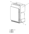
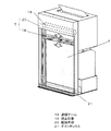
図1は本発明の実施の形態1における空気清浄装置の本体構成を示す概略斜視図、図2は同空気清浄装置の本体構成を示す概略断面図、図3は同自動清掃手段の配置と清掃部の動作を示す概略斜視図である。
(Embodiment 1)
1 is a schematic perspective view showing a main body configuration of an air cleaning device according to
図1に示すように、略箱形状の本体ケース1の側面に吸込口2が開口し、天面には吹出口3が開口している。図2に示すように、本体ケース1内部には粗じんやほこりを除去するプレフィルタ4を有する空気清浄手段5が立設されており、前述した吸込口2、空気清浄手段5、吹出口3を空気がこの順に通過できる空気清浄経路6が形成されている。
As shown in FIG. 1, a
この空気清浄経路6に対して空気清浄手段5は前段側にプレフィルタ4を配しており、プレフィルタ4の上流側には、図3に示すようにプレフィルタ4に付着した粗じんやホコリを自動で清掃する自動清掃手段7が配設されている。そして、図2に戻り、空気清浄手段5の後段側には空気清浄経路6を形成する送風手段8が配設されており、外部の空気を本体ケース1内部に取り込み、空気清浄手段5を通過させ、吹出口3から本体ケース1外部へと排出することができる。
The air cleaning means 5 is provided with a
上記構成とすることにより、送風手段8により本体ケース1内に取り込まれた空気を空気清浄手段5 によってろ過して清浄化し、清浄化された空気を吹出口3 から本体ケース1外へ排出することができる。これにより、対象空間の空気の清浄化を行うことができる。そして、ある所定の運転時間が経過し、粗じんやホコリが付着することによりプレフィルタ4が閉塞し、送風手段8によって送風される風量が低下した場合、自動清掃手段7の運転を行う制御が作動する。この自動清掃手段7の作用によりプレフィルタ4から粗じんやホコリが取り除かれるので、送風手段8により送風される風量が回復する。
By adopting the above configuration, the air taken into the
なお、空気清浄手段5としては、例えば、樹脂繊維を格子状に編んで形成される略平板形状のプレフィルタ4と、濾材を蛇腹状に折り曲げて形成される略直方体形状の集じんフィルタ9と、活性炭等の吸着剤を樹脂性の網に添着させた脱臭フィルタ10によって構成するものがあげられる。このような構成とすると、本体ケース1内に取り込まれた空気から粗じんやほこりを除去するとともに、花粉・細菌等の小さな粒子とタバコ臭等のにおいを除去し、空気を清浄化することができる。なお、本体ケース1内に取り込まれた空気が集じんフィルタ9と脱臭フィルタ10を通過する順番はどちらでもよい。
The air cleaning means 5 includes, for example, a substantially
なお、送風手段8として、例えば、シロッコファンやターボファン、プロペラファンやクロスフローファンが直流または交流電流によって駆動する電動機によって回転駆動するものが上げられる。シロッコファンであれば低回転数でも高い静圧がとれ、ターボファンであれば他よりファン効率がよく、プロペラファンであれば低回転数でも大きい風量がとれ、クロスフローファンであれば吹出気流が幅広にできるので、場合に応じて最適な方法を選択すればよい。 As the air blowing means 8, for example, a sirocco fan, a turbo fan, a propeller fan, or a cross flow fan that is rotationally driven by an electric motor driven by a direct current or an alternating current is raised. A sirocco fan can take high static pressure even at a low speed, a turbo fan has higher fan efficiency than a others, a propeller fan can take a large air volume even at a low speed, and a cross-flow fan produces a blown airflow. Since the width can be increased, an optimal method may be selected depending on the case.
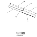
次に、自動清掃手段7の構成について、図4および図5を参照しながら説明する。図4は回転部材の構成を示す概略斜視図、図5は清掃アームの構成を示す概略斜視図である。 Next, the configuration of the automatic cleaning means 7 will be described with reference to FIGS. 4 and 5. FIG. 4 is a schematic perspective view showing the configuration of the rotating member, and FIG. 5 is a schematic perspective view showing the configuration of the cleaning arm.
図4に示すように、プレフィルタ4の一部を清掃する第一清掃手段11およびプレフィルタ4の残部を清掃する第二清掃手段12が回転部材13に備えられ、図5に示すようにこの回転部材13は回転部材フレーム14に回転可能に軸支されている。図4に戻るが、回転部材13は略樋形状に形成され、その長手方向側面に第一清掃手段11および第二清掃手段12が備えられている。なお、回転部材13の形状は略円筒形状や略半円筒形状としてもよい。
As shown in FIG. 4, the first cleaning means 11 for cleaning a part of the
第一清掃手段11と第二清掃手段12の長さ(回転部材の長手方向と同じ方向に対する長さをいう)は、清掃漏れがないよう、図4中の矢符15に示す第一清掃手段11の長さと矢符16に示す第二清掃手段12の長さの和が、矢符17に示す回転部材13の長手方向長さ以上の値となるように、それぞれ所定の長さに配置されている。ただし、第一清掃手段11と第二清掃手段12のそれぞれの長さは回転部材13の長手方向長さよりも短くなるように配置されている。
The lengths of the first cleaning means 11 and the second cleaning means 12 (referring to the length in the same direction as the longitudinal direction of the rotating member) are the first cleaning means indicated by the
ここで、第一清掃手段11および第二清掃手段12として、例えば、樹脂材料や金属材料によって成形された多毛ブラシ部材や、樹脂材料を多孔質成形したスポンジ部材、板状に成形されたゴム部材などが挙げられる。 Here, as the first cleaning means 11 and the second cleaning means 12, for example, a multi-brush brush member molded from a resin material or a metal material, a sponge member formed by porous molding of a resin material, or a rubber member molded into a plate shape Etc.
回転部材フレーム14は、図5に示すようにプレフィルタ4表面を上下方向に移動する清掃アーム18に対して着脱自在に配設されている。
As shown in FIG. 5, the rotating
清掃アーム18は、図3に戻るが、自動清掃運転が動作していない状態のときには、本体ケース1のプレフィルタ4の上方に設けられた静止位置19にて静止している(破線部)。電動機や組み合わせギアによって構成された駆動手段20が本体ケース1内に配置され、この清掃アーム18をプレフィルタ4の上下方向に移動させることができる。
Although the
また、プレフィルタ4から取り除かれた粗じんやホコリを貯留する貯留手段としてのダストボックス21が本体ケース1の下部に着脱自在に備えられている。
In addition, a
次に、回転部材13を回転させることによりプレフィルタ4と接触する清掃手段を第一清掃手段11と第二清掃手段12との間で切替える切替手段22の構成について、図6を参照しながら説明する。図6は回転部材13の構成を示す側方断面図である。
Next, the configuration of the switching unit 22 that switches the cleaning unit that contacts the
切替手段22は、図6の矢符23に示す回転部材13の回転方向に対して所定の角度をなして配置された第一清掃手段11および第二清掃手段12と、回転部材13の端面に回転部材フレーム14と接触することにより回転部材13の回転角度を規定するストッパーとして形成された複数の突起部24によって構成されている。
The switching means 22 includes a first cleaning means 11 and a second cleaning means 12 arranged at a predetermined angle with respect to the rotation direction of the rotating
第一清掃手段11と第二清掃手段12は、清掃アーム18が往路を移動する際に第一清掃手段11がプレフィルタ4に接触し、復路を移動する際に第二清掃手段12がプレフィルタ4に接触する角度に配置されている。ここで示す角度とは、回転部材13の回転軸を中心として第一清掃手段11と第二清掃手段12とがなす角度のことである。
The first cleaning means 11 and the second cleaning means 12 are such that when the
以下、その動作について図3、図7(a)および図7(b)を参照しながら説明する。図7(a)は清掃アーム18の下方から上方への移動方向変更時における回転部材13の動作を示す概略断面図であり、図7(b)は清掃アーム18の上方から下方への移動方向変更時における回転部材13の動作を示す概略断面図である。
Hereinafter, the operation will be described with reference to FIGS. 3, 7A and 7B. FIG. 7A is a schematic cross-sectional view showing the operation of the rotating
自動清掃運転が開始すると、図3に示すように駆動手段20の作用により清掃アーム18が静止位置19から下方へと動き出し、清掃アーム18が有している回転部材13に備えられた第一清掃手段11が、プレフィルタ4の一部を摺動しながらプレフィルタ4の上端から下端へと移動し、プレフィルタ4表面に付着した粗じんやホコリをプレフィルタ4から除去する。プレフィルタ4から除去された粗じんやホコリは本体下方に備えられたダストボックス21に落下し、貯留される。そして、プレフィルタ4の下端まで第一清掃手段11が達すると、駆動手段20の作用により清掃アーム18の進行方向が反転し、上方向へ動き出す。この静止位置19からプレフィルタ4の下端までの経路を往路と定義する。
When the automatic cleaning operation starts, as shown in FIG. 3, the cleaning
このとき、図7(a)に示すように、清掃アーム18の回転部材フレーム14に軸支された回転部材13は、第一清掃手段11とプレフィルタ4との間に摩擦力が働くことによって矢符25に示す方向に回転する。そして、回転部材13に形成されたストッパーとしての突起部24が回転部材フレーム14と接触し、回転部材13はそれ以上回転しなくなる。このとき、第一清掃手段11と第二清掃手段12とが所定の角度をなすように配置されているため、第二清掃手段12がちょうどプレフィルタ4と接触した位置で回転部材13の回転が止まることになる。
At this time, as shown in FIG. 7A, the rotating
そして、清掃アーム18が上方へと動き出すと、プレフィルタ4と接触している第二清掃手段12がプレフィルタ4の残部、すなわち、第一清掃手段11が清掃していない部分を摺動しながらプレフィルタ4の下方から上方へと移動し、プレフィルタ4表面に付着した粗じんやホコリを除去しながら静止位置19に達し、静止する。このプレフィルタ4の下端から静止位置19までの経路を復路と定義する。プレフィルタ4から除去された粗じんやホコリはダストボックス21へ落下し、貯留される。
When the
所定の時間の空気清浄運転が経過すると、再び自動清掃手段が運転を始め、清掃アーム18が下方へと動き出す。このとき、図7(b)に示すように、回転部材13は、第二清掃手段12とプレフィルタ4との間に働く摩擦力によって矢符26に示す方向に回転する。そして、回転部材13に形成されたストッパーとしての突起部24が回転部材フレーム14と接触し、回転部材13はそれ以上回転しなくなる。このとき、第一清掃手段11と第二清掃手段12が所定の角度をなして配置されているため、第一清掃手段11がちょうどプレフィルタ4と接触した位置で回転部材13の回転が止まることになる。そして、上記同様にプレフィルタ4上方から下方にかけて清掃アーム18が移動し、プレフィルタ4を清掃することができる。
When the air cleaning operation for a predetermined time elapses, the automatic cleaning means starts operating again, and the
ここで、従来のものは自動清掃手段によってプレフィルタ4を上方から下方にかけて清掃を行う際に、清掃手段としての回転ブラシ102が回転してプレフィルタ4表面を摺動することにより粗じんやホコリを除去するものであった。そして、回転ブラシ102が上方から下方にかけてプレフィルタ4全面を清掃しながら移動するものであった。したがって、プレフィルタ4全面を一度に清掃する構成であるため、回転ブラシ102とプレフィルタ4との接触領域が多く、回転ブラシ102にかかる摩擦抵抗が大きくなるので、回転ブラシ102を上方から下方に移動させる駆動手段105にかかる駆動負荷が大きなものであった。
Here, when the
本発明は上記したように、プレフィルタ4の清掃すべき範囲を第一清掃手段11と第二清掃手段12とに分担する、つまり、往路でプレフィルタ4の一部(図3では右半分)を清掃し、復路でプレフィルタ4の残部、すなわち、往路で清掃していない部分(図3では左半分)を清掃する構成としたため、清掃手段とプレフィルタ4が接触する面積を減らすことができる。したがって、清掃手段一つあたりのプレフィルタ4との摩擦抵抗が従来の方法よりも少なくなるので、清掃アーム18を動かすための駆動手段20にかかる負荷を少なくすることができる。
As described above, the present invention assigns the area to be cleaned of the
よって、自動清掃にかかる消費電力を減らすことができ、また、トルクが小さく小型で安価な駆動手段を使用することができるようになるものである。 Therefore, power consumption for automatic cleaning can be reduced, and a small and inexpensive driving means with a small torque can be used.
そして、自動清掃手段7は往路で清掃する第一清掃手段11と復路で清掃する第二清掃手段12を切り替える切替手段を有し、上記したように切替手段は切替手段がプレフィルタ4清掃の動作方向の変更に伴って順次自動で切り替えられる構成、すなわち、清掃アーム18の進行方向を切り替えると第一清掃手段11および第二清掃手段12とプレフィルタ4との摩擦によって回転部材13が回転して切替作用が行われる構成としたため、清掃手段の切替に他の動力手段を必要とせず、本体の構成を簡便化することができるようになるものである。
The automatic cleaning means 7 has a switching means for switching between the first cleaning means 11 for cleaning on the forward path and the second cleaning means 12 for cleaning on the return path. As described above, the switching means is an operation for cleaning the
上記したような構成および作用効果により、本発明における実施の形態1の空気清浄装置は所期の目的を達成することができるものである。
With the above-described configuration and operational effects, the air purifying apparatus according to
なお、本実施の形態では、清掃手段が2個の場合を説明したが、清掃手段を3個以上備えていてもよく、上記したように複数の清掃手段が切替手段によって順次切替えられる構成とすれば同様の効果が得られる。 In this embodiment, the case where there are two cleaning units has been described. However, three or more cleaning units may be provided, and a plurality of cleaning units are sequentially switched by the switching unit as described above. The same effect can be obtained.
(実施の形態2)
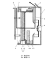
本発明における実施の形態2について、図面を参照しながら説明する。実施の形態1と同様の作用効果を有する構成については同一符号を用い、詳細な説明は省略する。なお、以下に説明する内容は本発明実施の一例に過ぎず、これに限定されるものではない。図8は本発明の実施の形態2における加湿機能付き空気清浄装置の本体構成を示す概略断面図である。
(Embodiment 2)
A second embodiment of the present invention will be described with reference to the drawings. The same reference numerals are used for configurations having the same effects as those of the first embodiment, and detailed description thereof is omitted. Note that the content described below is merely an example of the present invention and is not limited thereto. FIG. 8 is a schematic cross-sectional view showing a main body configuration of an air cleaning device with a humidifying function according to
図8に示すように、例えば実施の形態1における空気清浄経路6に、送風手段8によって送風される空気を加湿する加湿手段27が介在されている。すなわち、本体ケース1の下部に水を貯留する略桶形状の加湿トレイ28と加湿に使用される水を貯留するための図示しない加湿タンクが配置されており、加湿トレイ28の内部空間には加湿手段27が立設され、この加湿手段27は空気清浄手段5と送風手段8の間に配置されている。
As shown in FIG. 8, for example, a
このとき、本体ケース1の吸込口2から吸い込まれて空気清浄手段5を通過した空気の一部または全部がこの加湿手段27を通過して加湿され、送風手段8によって本体ケース1外部へと排出される。このようにして、本発明の加湿機能付き空気清浄装置は、本体ケース1に吸い込んだ空気を空気清浄するとともに空気の加湿を行うことができるものである。
At this time, a part or all of the air sucked from the
ここで、加湿手段27として、例えば、吸水性のある不織布を蛇腹状に折り曲げたものや少なくとも一部に耐水性および吸水性のある合成繊維を使用して編んで作成した立体編物の一端を加湿トレイ28に貯留した水に沈めて吸水させ、これに空気を通過させて水が気化する作用により加湿を行う方法や、耐水性のある合成繊維を編みこんで作製して保水性を持たせた立体編物を電動機等の駆動手段によって加湿トレイ28に貯留した水への浸水と取出しを定期的に繰り返すようにし、この立体編物に空気を通過させて水が気化する作用により加湿を行う方法、または、円盤状の回転部材をその円盤面を略水平となるように配置し、円盤中心を通り円盤面に垂直な方向を回転軸として回転させ、この回転部材の上面に加湿トレイ28に貯留された水を供給し、回転による遠心力によって水を微細な水滴に分裂させ、この微細な水滴に対して空気を当てるように通過させ水滴を気化させて加湿を行う方法、超音波領域の振動数で振動する超音波振動子を加湿トレイ28に貯留した水に水没するように配置し、この超音波振動子の振動によって水を微細な水滴に分裂させ、この微細な水滴に対して空気を当てるように通過させて水滴を気化させて加湿を行う方法、電熱線またはセラミックヒータなどの発熱素子によって加湿トレイ28に貯留した水を加熱し、蒸発した水蒸気と空気を混合させることによって加湿を行う方法などがあげられる。
Here, as the humidifying means 27, for example, one end of a three-dimensional knitted fabric made by bending a water-absorbing nonwoven fabric into a bellows shape or knitting at least partially using a synthetic fiber having water resistance and water absorption is humidified. The water stored in the
本発明にかかるフィルタ自動清掃装置は、自動清掃にかかる消費電力を低減でき、また、小型で安価な駆動手段を使用することを可能とするものであるので、家庭用や事務所用などの、空気清浄装置および加湿機能付き空気清浄装置のフィルタ自動清掃装置やエアコンのフィルタの自動清掃装置などとして活用が大いに期待されるものである。 The filter automatic cleaning device according to the present invention can reduce power consumption required for automatic cleaning, and can use a small and inexpensive driving means. It is greatly expected to be used as an automatic filter cleaning device for an air cleaning device and an air cleaning device with a humidifying function, an automatic cleaning device for an air conditioner filter, and the like.
1 本体ケース
2 吸込口
3 吹出口
4 プレフィルタ
5 空気清浄手段
6 空気清浄経路
7 自動清掃手段
8 送風手段
11 第一清掃手段
12 第二清掃手段
13 回転部材
27 加湿手段
DESCRIPTION OF
Claims (6)
前記自動清掃手段は、
少なくとも1度前記フィルタの表面を往復移動するものであって、
前記フィルタの一部を清掃する清掃手段を複数有し、
複数の前記清掃手段を順次切り替えて前記フィルタに接触させる切替手段を備えることを特徴とするフィルタ自動清掃装置。 Equipped with an automatic cleaning means that automatically cleans the filter to remove coarse dust and dust,
The automatic cleaning means includes
Reciprocating the surface of the filter at least once,
A plurality of cleaning means for cleaning a part of the filter;
A filter automatic cleaning device comprising switching means for sequentially switching a plurality of the cleaning means to contact the filter.
自動清掃手段によるフィルタ清掃の動作方向の変更によって自動で前記清掃手段を順次切り替えることを特徴とする請求項1に記載のフィルタ自動清掃装置。 Switching means is
2. The automatic filter cleaning apparatus according to claim 1, wherein the cleaning means is automatically and sequentially switched by changing the operation direction of the filter cleaning by the automatic cleaning means.
往路でフィルタの一部を清掃する第一清掃手段と、
復路で前記フィルタの残部を清掃する第二清掃手段であり、
切替手段は、
前記自動清掃手段による前記フィルタの動作方向の変更に伴って回転する回転部材を備え、
前記第一清掃手段と前記第二清掃手段は、
前記回転部材の側面に備えられ、
前記第一清掃手段と前記第二清掃手段は前記回転部材の回転方向に対して所定の角度をなして配置されていることを特徴とする請求項1または2に記載のフィルタ自動清掃装置。 Multiple cleaning means
A first cleaning means for cleaning a part of the filter in the outward path;
A second cleaning means for cleaning the remaining part of the filter in the return path;
Switching means is
A rotating member that rotates in accordance with a change in the operation direction of the filter by the automatic cleaning means;
The first cleaning means and the second cleaning means are:
Provided on a side surface of the rotating member;
3. The automatic filter cleaning apparatus according to claim 1, wherein the first cleaning unit and the second cleaning unit are arranged at a predetermined angle with respect to a rotation direction of the rotating member.
自動清掃手段から着脱自在に配設されていることを特徴とする請求項3に記載のフィルタ自動清掃装置。 The rotating member is
4. The automatic filter cleaning device according to claim 3, wherein the automatic filter cleaning device is detachably disposed from the automatic cleaning means.
前記本体ケース内に設けられ、粗じんやほこりを除去するフィルタを有する空気清浄手段と、
前記吸込口、前記空気清浄手段、前記吹出口の順に空気が通過する空気清浄経路と、
前記空気清浄経路に送風する送風手段と、
請求項1〜4のいずれかに記載のフィルタ自動清掃装置を備えた空気清浄装置。 A main body case having an inlet and an outlet, and
Air cleaning means provided in the main body case and having a filter for removing coarse dust and dust,
An air purification path through which air passes in the order of the suction port, the air cleaning means, and the air outlet;
A blowing means for blowing air to the air cleaning path;
An air cleaning device comprising the automatic filter cleaning device according to claim 1.
Priority Applications (1)
| Application Number | Priority Date | Filing Date | Title |
|---|---|---|---|
| JP2011006596A JP5845387B2 (en) | 2011-01-17 | 2011-01-17 | Filter automatic cleaning device, air cleaning device using the same, and air cleaning device with humidification function |
Applications Claiming Priority (1)
| Application Number | Priority Date | Filing Date | Title |
|---|---|---|---|
| JP2011006596A JP5845387B2 (en) | 2011-01-17 | 2011-01-17 | Filter automatic cleaning device, air cleaning device using the same, and air cleaning device with humidification function |
Publications (2)
| Publication Number | Publication Date |
|---|---|
| JP2012148207A true JP2012148207A (en) | 2012-08-09 |
| JP5845387B2 JP5845387B2 (en) | 2016-01-20 |
Family
ID=46791033
Family Applications (1)
| Application Number | Title | Priority Date | Filing Date |
|---|---|---|---|
| JP2011006596A Active JP5845387B2 (en) | 2011-01-17 | 2011-01-17 | Filter automatic cleaning device, air cleaning device using the same, and air cleaning device with humidification function |
Country Status (1)
| Country | Link |
|---|---|
| JP (1) | JP5845387B2 (en) |
Cited By (5)
| Publication number | Priority date | Publication date | Assignee | Title |
|---|---|---|---|---|
| CN104153066A (en) * | 2014-07-21 | 2014-11-19 | 苏州凯枫瑞电子科技有限公司 | Auto-control textile dust-removing pipe structure |
| WO2016185735A1 (en) * | 2015-05-20 | 2016-11-24 | シャープ株式会社 | Air purifier |
| JP2018511401A (en) * | 2015-04-14 | 2018-04-26 | 青▲島▼海▲尓▼洗衣机有限公司 | Filter system and clothes dryer with self-cleaning function |
| CN114931808A (en) * | 2022-06-25 | 2022-08-23 | 嘉兴市永泉织染有限公司 | Integrated textile wastewater treatment equipment |
| KR102478660B1 (en) * | 2022-05-08 | 2022-12-19 | 주식회사 팍스디앤엠 | Ventilation and dust collection system |
Citations (5)
| Publication number | Priority date | Publication date | Assignee | Title |
|---|---|---|---|---|
| JPS586226A (en) * | 1981-07-03 | 1983-01-13 | Toshiba Corp | Switchboard |
| JPS6311577U (en) * | 1986-07-10 | 1988-01-26 | ||
| US6007607A (en) * | 1997-04-04 | 1999-12-28 | Rieter Ingolstadt Spinnereimaschinenbau Ag | Apparatus and process for cleaning filters in a textile machine using a moveable scraper assembly |
| JP2007271170A (en) * | 2006-03-31 | 2007-10-18 | Fujitsu General Ltd | Air conditioner |
| JP2008122047A (en) * | 2006-11-16 | 2008-05-29 | Daikin Ind Ltd | Air conditioner |
-
2011
- 2011-01-17 JP JP2011006596A patent/JP5845387B2/en active Active
Patent Citations (5)
| Publication number | Priority date | Publication date | Assignee | Title |
|---|---|---|---|---|
| JPS586226A (en) * | 1981-07-03 | 1983-01-13 | Toshiba Corp | Switchboard |
| JPS6311577U (en) * | 1986-07-10 | 1988-01-26 | ||
| US6007607A (en) * | 1997-04-04 | 1999-12-28 | Rieter Ingolstadt Spinnereimaschinenbau Ag | Apparatus and process for cleaning filters in a textile machine using a moveable scraper assembly |
| JP2007271170A (en) * | 2006-03-31 | 2007-10-18 | Fujitsu General Ltd | Air conditioner |
| JP2008122047A (en) * | 2006-11-16 | 2008-05-29 | Daikin Ind Ltd | Air conditioner |
Cited By (5)
| Publication number | Priority date | Publication date | Assignee | Title |
|---|---|---|---|---|
| CN104153066A (en) * | 2014-07-21 | 2014-11-19 | 苏州凯枫瑞电子科技有限公司 | Auto-control textile dust-removing pipe structure |
| JP2018511401A (en) * | 2015-04-14 | 2018-04-26 | 青▲島▼海▲尓▼洗衣机有限公司 | Filter system and clothes dryer with self-cleaning function |
| WO2016185735A1 (en) * | 2015-05-20 | 2016-11-24 | シャープ株式会社 | Air purifier |
| KR102478660B1 (en) * | 2022-05-08 | 2022-12-19 | 주식회사 팍스디앤엠 | Ventilation and dust collection system |
| CN114931808A (en) * | 2022-06-25 | 2022-08-23 | 嘉兴市永泉织染有限公司 | Integrated textile wastewater treatment equipment |
Also Published As
| Publication number | Publication date |
|---|---|
| JP5845387B2 (en) | 2016-01-20 |
Similar Documents
| Publication | Publication Date | Title |
|---|---|---|
| CN101451750B (en) | Apparatus for purifying and humidifying air | |
| JP6208130B2 (en) | Air filtration and air purification equipment | |
| JP5845387B2 (en) | Filter automatic cleaning device, air cleaning device using the same, and air cleaning device with humidification function | |
| KR101691259B1 (en) | Humidifier | |
| JP5225601B2 (en) | Air conditioner | |
| JP2012167873A (en) | Dust removing device, air cleaning device including the same, and air cleaning device with humidifying function | |
| KR20200107067A (en) | Wet type multifunction air filter | |
| JP2018044762A (en) | Humidification air cleaner | |
| JP2011226670A (en) | Air cleaning equipment with humidifying function | |
| JP5861990B2 (en) | Air conditioner | |
| WO2016031784A1 (en) | Air purifier | |
| KR101321602B1 (en) | Wet Typer of Apparatus for Filtering with Function of Cleaning, Air Freshener,Sterilization and Humidification | |
| JP5690997B2 (en) | Humidified air purifier | |
| KR101307842B1 (en) | Disk assembly handle of humidifying air cleaner | |
| JP2011252653A (en) | Air cleaner, and air cleaner with humidifying function | |
| JP2013070791A (en) | Air purifier | |
| JP6050371B2 (en) | Dehumidification type air purifier | |
| JP6281593B2 (en) | Air cleaner | |
| JP6149954B2 (en) | Air conditioner | |
| JP2010169320A (en) | Air cleaning device and air cleaning device with humidification function | |
| JP5983801B2 (en) | Air conditioner | |
| WO2015186804A1 (en) | Air cleaner | |
| JPWO2018185952A1 (en) | Louvers and blowers | |
| KR101795421B1 (en) | Humidificator using humidification filters | |
| JP2012007786A (en) | Humidifier, and air cleaner |
Legal Events
| Date | Code | Title | Description |
|---|---|---|---|
| A621 | Written request for application examination |
Free format text: JAPANESE INTERMEDIATE CODE: A621 Effective date: 20131226 |
|
| RD01 | Notification of change of attorney |
Free format text: JAPANESE INTERMEDIATE CODE: A7421 Effective date: 20140115 |
|
| RD01 | Notification of change of attorney |
Free format text: JAPANESE INTERMEDIATE CODE: A7421 Effective date: 20140418 |
|
| A977 | Report on retrieval |
Free format text: JAPANESE INTERMEDIATE CODE: A971007 Effective date: 20140918 |
|
| A131 | Notification of reasons for refusal |
Free format text: JAPANESE INTERMEDIATE CODE: A131 Effective date: 20140924 |
|
| A711 | Notification of change in applicant |
Free format text: JAPANESE INTERMEDIATE CODE: A711 Effective date: 20141007 |
|
| A521 | Written amendment |
Free format text: JAPANESE INTERMEDIATE CODE: A523 Effective date: 20141022 |
|
| A131 | Notification of reasons for refusal |
Free format text: JAPANESE INTERMEDIATE CODE: A131 Effective date: 20150428 |
|
| A521 | Written amendment |
Free format text: JAPANESE INTERMEDIATE CODE: A523 Effective date: 20150512 |
|
| TRDD | Decision of grant or rejection written | ||
| A01 | Written decision to grant a patent or to grant a registration (utility model) |
Free format text: JAPANESE INTERMEDIATE CODE: A01 Effective date: 20150602 |
|
| A61 | First payment of annual fees (during grant procedure) |
Free format text: JAPANESE INTERMEDIATE CODE: A61 Effective date: 20150615 |
|
| R151 | Written notification of patent or utility model registration |
Ref document number: 5845387 Country of ref document: JP Free format text: JAPANESE INTERMEDIATE CODE: R151 |