JP2012147976A - Optical coherence tomographic imaging method and apparatus - Google Patents
Optical coherence tomographic imaging method and apparatus Download PDFInfo
- Publication number
- JP2012147976A JP2012147976A JP2011009345A JP2011009345A JP2012147976A JP 2012147976 A JP2012147976 A JP 2012147976A JP 2011009345 A JP2011009345 A JP 2011009345A JP 2011009345 A JP2011009345 A JP 2011009345A JP 2012147976 A JP2012147976 A JP 2012147976A
- Authority
- JP
- Japan
- Prior art keywords
- eye
- distance
- examined
- tomographic image
- objective lens
- Prior art date
- Legal status (The legal status is an assumption and is not a legal conclusion. Google has not performed a legal analysis and makes no representation as to the accuracy of the status listed.)
- Granted
Links
Images


Landscapes
- Eye Examination Apparatus (AREA)
Abstract
Description
本発明は、光断層画像撮像方法及び光断層画像撮像装置に関し、特に、眼科診療等に用いられる光断層画像撮像方法及び光断層画像撮像装置に関する。 The present invention relates to an optical tomographic image capturing method and an optical tomographic image capturing apparatus, and more particularly to an optical tomographic image capturing method and an optical tomographic image capturing apparatus used for ophthalmic medical care and the like.
現在、光学機器を用いた眼科用機器として、様々なものが使用されている。例えば、前眼部撮影機、眼底カメラ、共焦点レーザー走査検眼鏡(SLO:Scanning Laser Ophthalmoscope)等である。中でも、低コヒーレンス光を利用した光コヒーレンストモグラフィ(OCT:Optical Coherence Tomography)による光断層画像撮像装置は、被検眼の断層画像を高解像度に得ることができる装置であり、眼科用機器として網膜の専門外来では必要不可欠な装置になりつつある。以下、これをOCT装置と記す。 Currently, various types of ophthalmic equipment using optical equipment are used. For example, an anterior ocular segment photographing machine, a fundus camera, a confocal laser scanning ophthalmoscope (SLO), or the like. Among them, an optical tomographic imaging apparatus based on optical coherence tomography (OCT) using low-coherence light is an apparatus that can obtain a tomographic image of an eye to be examined with high resolution. It is becoming an indispensable device for specialized outpatients. Hereinafter, this is referred to as an OCT apparatus.
特許文献1の眼底観察装置は、眼底カメラユニット、OCTユニット、演算制御装置を含んで構成されている。眼底カメラは眼底の2次元画像を取得し、OCTユニットは眼底の断層画像を取得する。さらに、眼底の特徴部位を特定し、測定光の照射位置を変更して測定することができる。そして、眼底の断層画像や3次元画像を形成することができる。 The fundus oculi observation device of Patent Document 1 includes a fundus camera unit, an OCT unit, and an arithmetic control device. The fundus camera acquires a two-dimensional image of the fundus, and the OCT unit acquires a tomographic image of the fundus. Furthermore, the characteristic part of the fundus can be specified, and measurement can be performed by changing the irradiation position of the measurement light. Then, a fundus tomographic image or a three-dimensional image can be formed.
眼科で使われるOCT装置は被検眼と対物レンズの間隔であるワーキングディスタンスが変わると得られた断層画像の形状が変わる。これは眼球の形状の変化などを調査する用途に使えないことを意味する。 In the OCT apparatus used in ophthalmology, the shape of the obtained tomographic image changes when the working distance that is the distance between the eye to be examined and the objective lens changes. This means that it cannot be used to investigate changes in the shape of the eyeball.
上記課題を解決してワーキングディスタンスの変化に依存しない断層画像を得るために、本発明に係る断層画像撮像方法は、被検眼と対物レンズとの第一の距離を調整し、測定光を被検眼に照射することで得られる被検眼の網膜からの戻り光と参照光との合波光により、被検眼の断層画像を取得する光断層画像撮像方法であって、被検眼と対物レンズとの第一の距離を計測する第1の工程と、複数のライン状のデータからなる被検眼の断層画像を生成するための情報を取得する第2の工程と、計測した第一の距離に基づき、断層画像の複数のライン状データの各々における補正量を計算する第3の工程と、補正量を用いて、取得した情報から基準となる被検眼と対物レンズとの第二の距離で得られる断層画像を生成する第4の工程と、を有することを特徴とする。 In order to solve the above problems and obtain a tomographic image that does not depend on a change in working distance, a tomographic imaging method according to the present invention adjusts a first distance between an eye to be examined and an objective lens, and applies measurement light to the eye to be examined. An optical tomographic imaging method for obtaining a tomographic image of an eye to be inspected by a combined light of a return light from a retina of the eye to be obtained and a reference light obtained by irradiating the eye, wherein the first eye and the objective lens A tomographic image based on the first step of measuring the distance, the second step of acquiring information for generating a tomographic image of the eye to be examined comprising a plurality of line-shaped data, and the measured first distance A third step of calculating a correction amount in each of the plurality of line-shaped data, and using the correction amount, a tomographic image obtained at a second distance between the reference eye to be examined and the objective lens from the acquired information A fourth step of generating It is characterized in.
本発明によれば、ワーキングディスタンスの違いによる形状の違いを小さくすることができる。 According to the present invention, a difference in shape due to a difference in working distance can be reduced.
以下、本発明の一実施例につて、図面を用いて詳細に説明する。 Hereinafter, an embodiment of the present invention will be described in detail with reference to the drawings.
[実施例1]
図1は、実施例1における光断層画像撮像装置の構成を示す図である。
[Example 1]
FIG. 1 is a diagram illustrating a configuration of an optical tomographic imaging apparatus according to the first embodiment.
(光学系)
光断層画像撮像装置は、マイケルソン干渉系で構成されている。光源101の出射光102はシングルモードファイバ107に導かれて光カプラ108に入射し、光カプラ108にて参照光103と測定光104とに分割される。そして測定光104は、観察対象の網膜125の測定個所によって反射あるいは散乱され、戻り光105となって光カプラ108に戻る。そして光カプラ108によって、参照光路を経由してきた参照光103と合波され合波光106となり、分光器119に到達する。
(Optical system)
The optical tomographic imaging apparatus is configured by a Michelson interference system. The
光源101は代表的な低コヒーレント光源であるSLD光源(Super Luminescent Diode)である。波長は眼を測定することを鑑みると、近赤外光が適する。さらに波長は、得られる断層画像の横方向の分解能に影響するため、なるべく短波長であることが望ましく、ここでは中心波長840nm、波長幅50nmとする。当然観察対象の測定部位によっては、他の波長を選んでも良い。なお光源の種類は、ここではSLD光源を選択したが、低コヒーレント光が出射できればよく、ASE光源(Amplified Spontaneous Emission)等も用いることができる。
The
次に、参照光103の参照光路について説明する。光カプラ108によって分割された参照光103は、レンズ109−1にて略平行光となって出射される。その後参照光103は分散補償用ガラス110を通過してミラー111にて方向を変える。そして再び光カプラ108を介して分光器119に導かれる。なお、分散補償用ガラス110は被検眼124および走査光学系を測定光104が往復した時の分散を、参照光103に対して補償するものである。ここでは、その長さは、日本人の平均的な眼球の直径として代表的な値を想定し24mmとする。参照光の光路長は電動ステージ112で矢印の方向に移動することによってコヒーレンスゲートの位置を調整することができる。コヒーレンスゲートとは、測定光の光路上において、参照光の光路の長さと等距離になる位置のことである。電動ステージ112の制御はコンピュータ120によって行われる。
Next, the reference light path of the reference light 103 will be described. The reference light 103 divided by the
次に、測定光104の測定光路について説明する。光カプラ108によって分割された測定光104は、レンズ109−2にて、略平行光となって出射され、走査光学系を構成するXYスキャナ113のミラーに入射される。図1においてXYスキャナ113は一つのミラーとしているが、実際にはXスキャン用ミラーとYスキャン用ミラーとの2枚のミラーが近接して配置されている。測定光はレンズ114、ダイクロイックミラー115、対物レンズ128を介して被検眼124に到達する。
Next, the measurement optical path of the
ここで、前眼部すなわち角膜122の観察について説明する。前眼部の観察のための証明光は対物レンズの外側のリング状の光源(不図示)が使われる。この照明光が角膜122で反射し、その反射光が対物レンズ128を再度通過し、ダイクロイックミラー115で反射され、スプリットプリズム116、光学系117を介し、観察システム118に到達する。なお、スプリットプリズム116は、角膜122と共役の位置に配置されている。
Here, observation of the anterior segment, that is, the
また、対物レンズ128は被検眼124に向かい合って配置され、被検眼124に測定光を導く際にその形状を整形する。
Further, the
(ワーキングディスタンス)
次にワーキングディスタンスについて説明する。ここでは、ワーキングディスタンス126を角膜122表面と対物レンズ128表面との長さ(距離)とする。この長さは、本発明における第一の距離に対応する。まず、一般的なOCT装置の光学系は、被検眼124の瞳孔129が、測定光104の走査の回転中心となるように設計されている。そのためワーキングディスタンスを設計値になるように、対物レンズ128と被検眼123の距離を調整してOCT測定を行うことが望ましい。ただし、OCT装置は光学系のNAが小さいため焦点深度が深く、その結果、ワーキングディスタンスが設計値からはずれても問題なく撮像できる。なお、設計値から大きくはずれると光彩127によって光がブロックされたり、焦点がぼけたりすることになる。
(Working distance)
Next, working distance will be described. Here, the
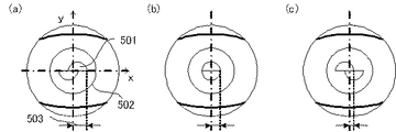
ここで図2の眼の模式図を用いてワーキングディスタンスと測定光の走査の回転中心202およびコヒーレンスゲートの軌跡205の関係について説明する。これらにおいて横軸がファストスキャンのx軸、縦軸が深さ方向のz軸とする。そして回転中心の原点を設計値である瞳孔の位置とする。なおこの図において回転中心202は、網膜201に入射する光線をそのまま延長したものが結んだ点であって、角膜や水晶体123で屈折した光が結ぶ点ではない。
Here, the relationship between the working distance, the
測定光の走査の回転中心202はワーキングディスタンス126の変化に伴って移動する。さらに測定光104を走査するときの走査半径204、走査角206もワーキングディスタンス126の変化に伴って変わる。また、xyスキャナ113は2枚のミラーからなることが多い。例えばy軸の回転中心は例えば1mm対物レンズ側にあるとする。このような場合、3D測定によるy軸方向の移動は別途補正をする必要がある。ここではx軸とy軸の回転中心が同じとして話を進める。
The
図2(a)は、ワーキングディスタンス126が設計値より短いため、回転中心202が瞳孔129に対して網膜201の方にある場合である。当然回転中心202と網膜201の距離は設計値より短くなる。なお、OCT測定において、コヒーレンスゲートは網膜201を観察できるように硝子体側に配置する。コヒーレンスゲートの軌跡205の位置はリファレンスミラー111によって変えることができる。図2(b)は、ワーキングディスタンス126が設計値とほぼ一致する時である。回転中心202と網膜201の距離は設計値である。図2(c)は、ワーキングディスタンス126が設計値より長く、回転中心202が瞳孔129に対して対物レンズ128側にある場合である。
FIG. 2A shows a case where the center of
これら図2(a)〜(c)のように走査半径204が長くなるほどその軌跡は平坦になる。つまりOCT装置では網膜201とコヒーレンスゲートの軌跡205の差が像となって表示される。そのため、走査半径204が長くなるほど見かけ上の湾曲が大きくなる。ただし、ワーキングディスタンス126が変化しても、光軸に対して同じ角度で入射する光同士は眼球の同じところに結像するという特性があるため、走査範囲207は大きく変わらない。
As shown in FIGS. 2A to 2C, the locus becomes flat as the
ここでさらに、ワーキングディスタンス126の距離変化と回転中心202の位置の関係について説明する。なお、ワーキングディスタンス126の設計値からの差210を空間距離で変数gとして表す。原点を瞳孔129にしているので、変数gの値はz軸の値である。また、基準のワーキングディスタンスは、本発明の第二の距離に相当し、例えば設計値(g=0)である。ここで回転中心202から網膜201までの空間距離は、変数gを用いてf(g)と表す。またコヒーレンスゲートは標準的な眼の網膜位置を基準とし、具体的には瞳孔から24mmの位置となる。その基準からz軸上の差203を空間距離で変数sとして表す。これらを用いて走査半径204L(g)は数式1のように表わされる。
![]()
![]()
コヒーレンスゲートの移動は、リファレンスミラー111の移動量ΔMに換算すると被検眼の屈折率nhを用いて数式2のように表わされる。
![]()
![]()
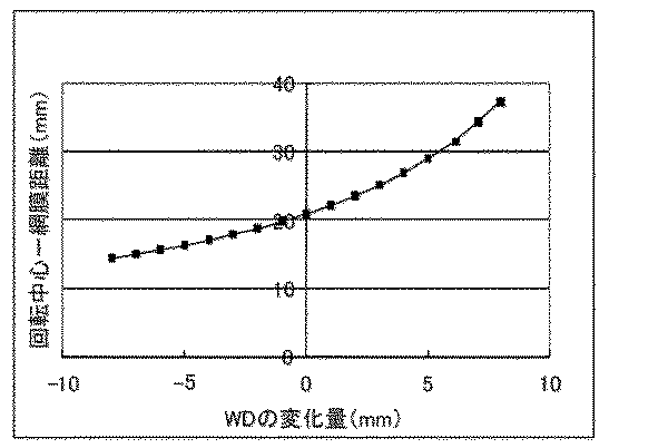
ところで、回転中心202から網膜201までの空間距離f(g)の変化は、ワーキングディスタンス126の変化に比例していない。その理由は角膜122や水晶体123で屈折するためである。図3に回転中心202から網膜201までの空間距離f(g)のシミュレーション結果を示す。横軸はワーキングディスタンス126の設計値からの変化gである。縦軸は回転中心202から網膜201までの空間距離である。ワーキングディスタンス126がマイナス側の時は、ワーキングディスタンス126の変化量より回転中心の移動が小さいことがわかる。逆にプラス側の時は、ワーキングディスタンス126の変化量より回転中心の移動が大きいことがわかる。このシミュレーションは眼軸長が24mmのモデルを使ったが、眼軸長が変わる場合はf(g)も当然変わる。この場合、それぞれの眼軸長のモデルに対してシミュレーションが必要となる。またx軸とy軸で回転中心が異なる場合はさらにシミュレーションが必要になる。
Incidentally, the change in the spatial distance f (g) from the
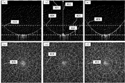
ここで、OCT装置によって模型眼を撮像した例について図4を用いて説明する。この模型眼は、網膜に相当する部分に放射状および円の模様が配置されている。網膜に相当する部分とはガラスの表面である。これらの撮像は、ワーキングディスタンス126を変化させ、断層画像において模型眼の網膜位置の頂点がコヒーレンスゲートから等距離になるように調整して測定した。図4(a)はワーキングディスタンス126が設計値より4mm短い場合の断層画像、図4(b)はその2次元投影像、図4(c)はワーキングディスタンス126が設計値の場合の断層画像、図4(d)はその2次元投影像、図4(e)はワーキングディスタンス126が設計値より4mm長い場合の断層画像、図4(f)はその2次元投影像である。なお、各断層画像には、模型眼の網膜が異なる曲率の円弧として撮像されている。また、投影像の同心円及び放射線は、模型眼の網膜位置に記された同心円及び放射線が撮像されそれが投影されている。円と直線の交点404に着目して、その補助線405を対応する断層画像に引くと図4(a)では補助線の下側、図4(e)では上側に、網膜の像が移動していることがわかる。ただし、図4(b)、(d)、(f)のように測定範囲はほぼ変化がない。
Here, the example which imaged the model eye with the OCT apparatus is demonstrated using FIG. In the model eye, radial and circular patterns are arranged in a portion corresponding to the retina. The portion corresponding to the retina is the surface of the glass. These images were measured by changing the
次に、ワーキングディスタンスの計測について図5を用いて説明する。図5は前眼部の観察システム118による角膜の像であり、瞳孔501、光彩502が観察されている状況である。瞳孔501の像はビームスプリットプリズムでx軸を境にy方向の正の領域と負の領域がそれぞれ分離されて観察システム118に結像するように設計されている。図5(a)はワーキングディスタンス126が設計値より短い場合、図5(b)はワーキングディスタンス126が設計値とほぼ一致する場合、図5(c)はワーキングディスタンス126が設計値より長い場合である。ワーキングディスタンス126が設計値とほぼ一致する場合には、瞳孔501は分離されていない像となる。一方ワーキングディスタンス126が設計値より短い場合には瞳孔の上の像は右側、長い場合には瞳孔の上の像は左側に移動する。この上下の瞳孔501の像の差503を計測することによってワーキングディスタンス126の長さを知ることができる。
Next, working distance measurement will be described with reference to FIG. FIG. 5 is an image of the cornea by the anterior ocular
ワーキングディスタンス126は上述した本発明における第一の距離に対応し、以上に述べたワーキングディスタンス126の長さを知る構成は、不図示の対物レンズ128の位置を調整する構成を加えて、本発明における第一の距離を調整及び計測する手段に対応する。或いは、このワーキングディスタンス126の長さを知る構成は、本発明における断層画像に対応する被検眼と対物レンズとの間の第一の距離を取得する取得手段に対応する。
The working
ちなみに、ワーキングディスタンス126とミラー111の移動量を測定すれば、回転中心から網膜までの距離を知ることができる。すなわち、コヒーレンスゲートを設計値に配置し、網膜と一致すれば設計通り24mmの眼軸長であることがわかる。一致していなければコヒーレンスゲートを移動し、網膜と一致するところを探す。この移動量から真の眼軸長を知ることができる。なお、網膜は厚みがあるが、例えば硝子体と神経線維層の境を設計値と考える。
Incidentally, the distance from the center of rotation to the retina can be determined by measuring the moving distance of the working
(信号処理)
ここで、OCT測定の信号処理について図6を用いて説明する。
(Signal processing)
Here, the signal processing of the OCT measurement will be described with reference to FIG.
A1工程で、測定を開始する。この状態はOCT装置が起動されていて、被検眼が測定位置に配置されている。 In step A1, measurement is started. In this state, the OCT apparatus is activated and the eye to be examined is placed at the measurement position.
本発明における第1の工程に対応するA2工程で、ワーキングディスタンス(WD)126調整と計測を行う。ここでは瞳孔の位置を座標系の原点とする。アライメントは前眼部観察システム118によって角膜122を観察しながら行う。ワーキングディスタンス126は設計値に対して±5mm程度に入ることを目標に調整を行う。特に湾曲が大きい場合、具体的には湾曲の値が所定値よりも大きい場合には、測定光が光彩などでブロックされない範囲でさらに対物レンズを被検眼に近づけてもよい。これは、湾曲を測定する手段を設けて、その測定値に応じて被検眼に近づける操作となる。当該操作を加えることにより、網膜の湾曲が大きな被検眼に対しても、好適に断層画像を得て後述するA3工程及びそれ以降の工程を実行することが可能となる。なお、マイナスとは対物レンズが角膜に近づく方向である。当然ワーキングディスタンスの調整とともにコヒーレンスゲートおよびフォーカスの位置を調整する。
In a step A2 corresponding to the first step in the present invention, the working distance (WD) 126 is adjusted and measured. Here, the position of the pupil is the origin of the coordinate system. The alignment is performed while observing the
本発明における第2の工程に対応するA3工程で、OCT測定を行う。走査範囲207は例えば黄斑を撮像する6mm、黄斑と乳頭を撮像する10mmなどである。ここでは、6mmの範囲を撮像するものとして、x方向には512ライン、y方向には512ラインのデータを取得する。分光器119からはライン毎に一次元配列のライン状データ(1024画素)が取得され、コンピュータ120に順次送られる。そしてx方向の連続する512ライン分を、2次元配列のデータを単位として保存する。そのデータサイズは1024×512×12ビットである。これがy方向に512枚できることになる。
OCT measurement is performed in step A3 corresponding to the second step in the present invention. The
測定した2次元配列のデータから、固定ノイズの除去、波長波数変換、フーリエ変換などを行って断層画像(B−Scan像)を得ることができる。この断層画像を確認し、所望の測定ができたと判断すれば、被検眼を測定位置から外す。以上のOCT測定を行う構成は、本発明における複数のライン状データからなる被検眼の断層画像を生成するための情報を取得する手段に対応する。 A tomographic image (B-Scan image) can be obtained from the measured two-dimensional array data by performing removal of fixed noise, wavelength wave number conversion, Fourier transform, and the like. If this tomographic image is confirmed and it is determined that a desired measurement has been made, the eye to be examined is removed from the measurement position. The above-described configuration for performing the OCT measurement corresponds to the means for acquiring information for generating a tomographic image of the eye to be inspected comprising a plurality of line data in the present invention.
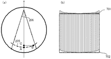
次に、本発明における第3の工程に対応するA4工程で、補正量を計算する。まず、一般的な断層画像は、コヒーレンスゲートの位置を基準に相対的に表示されている。しかし、図7(a)に示すようにコヒーレンスゲートの軌跡205は扇形の弧を描く。点Bをjライン目のスキャンであるとした時に、z軸上に投影したところを点Cとする。コヒーレンスゲートがz軸上の点Aに対してどれだけ変化するかの変化量d(g)を数式4で表わす。ここではワーキングディスタンスが設計値とg異なる場合の走査角(θ(g))206を用いて、スキャナがθ(g)/(N−1)ずつ回転するものとする。また、jは0〜N−1を満たす整数で、Nはx方向のライン数512である。
なお、ワーキングディスタンス126の変化によって網膜201から見た回転中心202から網膜201の距離f(g)、走査角206は変化するが、走査範囲207(W)はほぼ変わらないので、網膜201から見た走査角θ(g)は数式5のような関係がある。当然シミュレーションによってθ(g)を求めてもよい。
f(g)は図3に示すようにあらかじめシュミレーションしておけばよいので、dj(g)を求めることができる。この変化量dj(g)を求める数式を用いることで、前述したライン状データ各々の補正が可能となる。また、A4工程は、コンピュータ120により行われ、該コンピュータ120は本発明における複数のライン状データの各々における補正量を計算する手段に対応する。以上述べたように、A3工程では、被検眼と対物レンズとの第一の距離(g)、測定光を網膜の上で走査する際に網膜から見た走査の回転中心から網膜までの距離(f(g))、網膜から見た測定光を走査する際の走査角(θ(g))、および参照光の光路長により決まるコヒーレンスゲート位置(s)、に基づいてライン状データ各々の補正量が求められる。
Since f (g) may be simulated in advance as shown in FIG. 3, d j (g) can be obtained. By using the mathematical formula for obtaining the change amount d j (g), it is possible to correct each of the line-shaped data described above. Further, the A4 step is performed by the
更に、本発明の第4の工程に対応するA5工程で、断層画像を生成する。数式3は空間距離なので、屈折率nhをかけたのち、ピクセル分解能で除算を行い、シフトするピクセル数を計算する。図7(b)に、求めた補正量で各ライン701を補正した概念図を示す。この例は、ワーキングディスタンスの設計値に対して短い場合を示している。点線で示される全体の撮像範囲が、中心部分のラインを基準として画像を切り出されることを示している。データがない部分702はノイズレベルのデータを追加する。深さ方向にデータを余分に計算している場合にはそれを使って埋める。当然、基準となるワーキングディスタンスは設計値でなく、別の値であってもよい。
Furthermore, a tomographic image is generated in step A5 corresponding to the fourth step of the present invention. Since Equation 3 is a spatial distance, after multiplying the refractive index n h , division by pixel resolution is performed to calculate the number of pixels to be shifted. FIG. 7B shows a conceptual diagram in which each
A6工程で終了する。所望のデータが得られたことを確認して終了する。なお、以上の断層画像を生成する工程は、前述した第一の距離とは異なる被検眼と対物レンズとの基準のワーキングディスタンスである第二の距離に対応する断層画像に取得した断層画像を補正するコンピュータ120によって実施される。当該構成は、本発明における補正手段に対応する。
The process ends in step A6. After confirming that the desired data has been obtained, the process ends. Note that the above tomographic image generation step corrects the tomographic image acquired in the tomographic image corresponding to the second distance, which is the reference working distance between the eye to be examined and the objective lens, which is different from the first distance described above. Implemented by the
この結果、ワーキングディスタンスが設計値から異なるような場合であっても基準のワーキングディスタンスの画像を作ることができる。すなわち、湾曲の大きい人であっても湾曲を考慮した測定を行い、相対的に同じワーキングディスタンスの画像となる。 As a result, even if the working distance is different from the design value, an image of the reference working distance can be created. That is, even for a person with a large curvature, the measurement is performed in consideration of the curvature, and images with relatively the same working distance are obtained.
なお、前述したように、測定光は異なる回転軸すなわち回転中心をそれぞれ有する2つのxスキャナ及びyスキャナによって網膜上を操作される。従って、これらスキャナの回転中心の位置の相違を考慮して、断層画像の補正を行う必要がある。本発明では、第4の工程において、このような回転中心の違いをワーキングディスタンスに反映させた断層画像を生成することとしても良い。これにより、実際のOCT装置において、より適正な断層画像を得ることが可能となる。 As described above, the measurement light is operated on the retina by two x scanners and y scanners each having different rotation axes, that is, rotation centers. Therefore, it is necessary to correct the tomographic image in consideration of the difference in the position of the rotation center of these scanners. In the present invention, in the fourth step, a tomographic image in which such a difference in the rotation center is reflected in the working distance may be generated. As a result, a more appropriate tomographic image can be obtained in an actual OCT apparatus.
以上説明のように本実施例によれば、被検眼と対物レンズのワーキングディスタンスの調整と計測を行い、画像を補正することによって、ワーキングディスタンスの違いによる形状の違いを小さくすることができる。また、湾曲が大きい被検眼の場合であっても、得られた断層画像を形状の解析に使うことができる。また、撮像時に、ワーキングディスタンスを設計値に合わせる必要がなくなるため測定時間の短縮が可能になる。 As described above, according to the present embodiment, by adjusting and measuring the working distance of the eye to be examined and the objective lens and correcting the image, the difference in shape due to the difference in working distance can be reduced. Even in the case of an eye to be examined having a large curvature, the obtained tomographic image can be used for shape analysis. Further, it is not necessary to match the working distance to the design value at the time of imaging, so that the measurement time can be shortened.
(その他の実施例)
また、本発明は、以下の処理を実行することによっても実現される。即ち、上述した実施形態の機能を実現するソフトウェア(プログラム)を、ネットワーク又は各種記憶媒体を介してシステム或いは装置に供給し、そのシステム或いは装置のコンピュータ(またはCPUやMPU等)がプログラムを読み出して実行する処理である。
(Other examples)
The present invention can also be realized by executing the following processing. That is, software (program) that realizes the functions of the above-described embodiments is supplied to a system or apparatus via a network or various storage media, and a computer (or CPU, MPU, or the like) of the system or apparatus reads the program. It is a process to be executed.
Claims (9)
前記被検眼と対物レンズとの前記第一の距離を計測する第1の工程と、
複数のライン状のデータからなる前記被検眼の断層画像を生成するための情報を取得する第2の工程と、
計測した前記第一の距離に基づき、前記断層画像の前記複数のライン状データの各々における補正量を計算する第3の工程と、
前記補正量を用いて、取得した前記情報から基準となる前記被検眼と前記対物レンズとの第二の距離で得られる断層画像を生成する第4の工程と、
を有することを特徴とする光断層画像撮像方法。 The first distance between the eye to be examined and the objective lens is adjusted, and the combined light of the return light from the retina of the eye to be examined and the reference light obtained by irradiating the eye to be examined with measurement light, An optical tomographic imaging method for obtaining a tomographic image,
A first step of measuring the first distance between the eye to be examined and the objective lens;
A second step of acquiring information for generating a tomographic image of the eye to be examined comprising a plurality of line-shaped data;
A third step of calculating a correction amount in each of the plurality of line-shaped data of the tomographic image based on the measured first distance;
A fourth step of generating a tomographic image obtained at a second distance between the eye to be examined and the objective lens from the acquired information using the correction amount;
An optical tomographic imaging method characterized by comprising:
前記第4の工程は、前記断層画像を生成するときに、各々の前記スキャナの前記回転中心の位置の違いを補正する工程を更に有することを特徴とする請求項1または2記載の光断層画像撮像方法。 Two scanners each having a different center of rotation for scanning the measuring light,
The optical tomographic image according to claim 1, wherein the fourth step further includes a step of correcting a difference in position of the rotation center of each of the scanners when generating the tomographic image. Imaging method.
前記断層画像に対応する前記被検眼と前記対物レンズとの第一の距離を取得する取得手段と、
前記断層画像を、前記第一の距離とは異なる前記被検眼と対物レンズとの第二の距離に対応する断層画像に補正する補正手段と、
を有することを特徴とする光断層画像撮像装置。 An optical tomographic imaging apparatus that acquires a tomographic image of the eye to be inspected based on a combined light obtained by combining the return light from the eye to be examined irradiated with the measurement light via the objective lens and the reference light corresponding to the measurement light Because
Obtaining means for obtaining a first distance between the eye to be examined and the objective lens corresponding to the tomographic image;
Correction means for correcting the tomographic image to a tomographic image corresponding to a second distance between the eye to be examined and the objective lens different from the first distance;
An optical tomographic imaging apparatus characterized by comprising:
前記補正手段は、前記断層画像を生成するときに、各々の前記スキャナの前記回転中心の位置の違いを補正することを特徴とする請求項5乃至7の何れか1項記載の光断層画像撮像装置。 Two scanners each having a different center of rotation for scanning the measuring light,
The optical tomographic imaging according to claim 5, wherein the correction unit corrects a difference in position of the rotation center of each of the scanners when generating the tomographic image. apparatus.
Priority Applications (5)
| Application Number | Priority Date | Filing Date | Title |
|---|---|---|---|
| JP2011009345A JP5782262B2 (en) | 2011-01-20 | 2011-01-20 | Tomographic image correction method and tomographic image correction apparatus |
| US13/286,481 US8517537B2 (en) | 2011-01-20 | 2011-11-01 | Optical coherence tomographic imaging method and optical coherence tomographic imaging apparatus |
| KR1020110116745A KR101442519B1 (en) | 2011-01-20 | 2011-11-10 | Optical coherence tomographic imaging method and optical coherence tomographic imaging apparatus |
| EP11189104A EP2478830A3 (en) | 2011-01-20 | 2011-11-15 | Optical coherence tomographic imaging method and apparatus |
| CN201110397461.3A CN102599882B (en) | 2011-01-20 | 2011-11-30 | Optical coherence tomographic imaging method and apparatus |
Applications Claiming Priority (1)
| Application Number | Priority Date | Filing Date | Title |
|---|---|---|---|
| JP2011009345A JP5782262B2 (en) | 2011-01-20 | 2011-01-20 | Tomographic image correction method and tomographic image correction apparatus |
Publications (3)
| Publication Number | Publication Date |
|---|---|
| JP2012147976A true JP2012147976A (en) | 2012-08-09 |
| JP2012147976A5 JP2012147976A5 (en) | 2014-03-06 |
| JP5782262B2 JP5782262B2 (en) | 2015-09-24 |
Family
ID=46790865
Family Applications (1)
| Application Number | Title | Priority Date | Filing Date |
|---|---|---|---|
| JP2011009345A Expired - Fee Related JP5782262B2 (en) | 2011-01-20 | 2011-01-20 | Tomographic image correction method and tomographic image correction apparatus |
Country Status (1)
| Country | Link |
|---|---|
| JP (1) | JP5782262B2 (en) |
Cited By (7)
| Publication number | Priority date | Publication date | Assignee | Title |
|---|---|---|---|---|
| JP2016220735A (en) * | 2015-05-27 | 2016-12-28 | 株式会社トーメーコーポレーション | Optical coherence tomography device and control method thereof |
| JP2017108995A (en) * | 2015-12-18 | 2017-06-22 | 株式会社トプコン | Ophthalmic equipment |
| JP2017534382A (en) * | 2014-10-17 | 2017-11-24 | オプティメディカ・コーポレイションOptimedica Corporation | Automatic patient positioning of laser eye surgery system |
| CN108371541A (en) * | 2018-03-20 | 2018-08-07 | 视微影像(河南)科技有限公司 | A kind of tool for detecting and calibrating ophthalmology imaging, ophthalmology biological parameter measuring instrument |
| JP2019203892A (en) * | 2018-05-21 | 2019-11-28 | コー・ヤング・テクノロジー・インコーポレーテッド | Oct system, method of generating oct image and storage medium |
| JP2019213751A (en) * | 2018-06-14 | 2019-12-19 | 株式会社トプコン | Ophthalmologic apparatus and control method thereof |
| US12087001B2 (en) | 2019-11-29 | 2024-09-10 | Canon Kabushiki Kaisha | Medical image processing apparatus, optical coherence tomography apparatus, medical image processing method, and computer-readable medium |
Citations (10)
| Publication number | Priority date | Publication date | Assignee | Title |
|---|---|---|---|---|
| JP2001231754A (en) * | 2000-02-24 | 2001-08-28 | Canon Inc | Ophthalmometer |
| JP2002515593A (en) * | 1998-05-15 | 2002-05-28 | レーザー・ディアグノスティック・テクノロジーズ・インコーポレイテッド | Method and apparatus for recording three-dimensional distribution of scattered light |
| JP2007275375A (en) * | 2006-04-07 | 2007-10-25 | Topcon Corp | Ophthalmic equipment |
| JP2008188047A (en) * | 2007-01-31 | 2008-08-21 | Nidek Co Ltd | Ocular axial length measuring apparatus |
| JP2008289579A (en) * | 2007-05-23 | 2008-12-04 | Topcon Corp | Fundus observation apparatus and program for controlling the same |
| JP2009160190A (en) * | 2007-12-29 | 2009-07-23 | Nidek Co Ltd | Ophthalmic imaging apparatus |
| JP2010197180A (en) * | 2009-02-25 | 2010-09-09 | Kowa Co | Optical image measuring device |
| JP2010200920A (en) * | 2009-03-02 | 2010-09-16 | Canon Inc | Image processing apparatus and method for controlling the same |
| JP2010210268A (en) * | 2009-03-06 | 2010-09-24 | Canon Inc | Optical interference tomographic imaging method and apparatus |
| JP2010279439A (en) * | 2009-06-02 | 2010-12-16 | Canon Inc | Image processor, method for controlling the same and computer program |
-
2011
- 2011-01-20 JP JP2011009345A patent/JP5782262B2/en not_active Expired - Fee Related
Patent Citations (10)
| Publication number | Priority date | Publication date | Assignee | Title |
|---|---|---|---|---|
| JP2002515593A (en) * | 1998-05-15 | 2002-05-28 | レーザー・ディアグノスティック・テクノロジーズ・インコーポレイテッド | Method and apparatus for recording three-dimensional distribution of scattered light |
| JP2001231754A (en) * | 2000-02-24 | 2001-08-28 | Canon Inc | Ophthalmometer |
| JP2007275375A (en) * | 2006-04-07 | 2007-10-25 | Topcon Corp | Ophthalmic equipment |
| JP2008188047A (en) * | 2007-01-31 | 2008-08-21 | Nidek Co Ltd | Ocular axial length measuring apparatus |
| JP2008289579A (en) * | 2007-05-23 | 2008-12-04 | Topcon Corp | Fundus observation apparatus and program for controlling the same |
| JP2009160190A (en) * | 2007-12-29 | 2009-07-23 | Nidek Co Ltd | Ophthalmic imaging apparatus |
| JP2010197180A (en) * | 2009-02-25 | 2010-09-09 | Kowa Co | Optical image measuring device |
| JP2010200920A (en) * | 2009-03-02 | 2010-09-16 | Canon Inc | Image processing apparatus and method for controlling the same |
| JP2010210268A (en) * | 2009-03-06 | 2010-09-24 | Canon Inc | Optical interference tomographic imaging method and apparatus |
| JP2010279439A (en) * | 2009-06-02 | 2010-12-16 | Canon Inc | Image processor, method for controlling the same and computer program |
Cited By (15)
| Publication number | Priority date | Publication date | Assignee | Title |
|---|---|---|---|---|
| JP2017534382A (en) * | 2014-10-17 | 2017-11-24 | オプティメディカ・コーポレイションOptimedica Corporation | Automatic patient positioning of laser eye surgery system |
| US11331220B2 (en) | 2014-10-17 | 2022-05-17 | Amo Development, Llc | Automatic patient positioning within a laser eye surgery system |
| JP2016220735A (en) * | 2015-05-27 | 2016-12-28 | 株式会社トーメーコーポレーション | Optical coherence tomography device and control method thereof |
| US10932664B2 (en) | 2015-12-18 | 2021-03-02 | Topcon Corporation | Ophthalmic device |
| JP2017108995A (en) * | 2015-12-18 | 2017-06-22 | 株式会社トプコン | Ophthalmic equipment |
| US20190000316A1 (en) * | 2015-12-18 | 2019-01-03 | Topcon Corporation | Ophthalmic device |
| CN108371541A (en) * | 2018-03-20 | 2018-08-07 | 视微影像(河南)科技有限公司 | A kind of tool for detecting and calibrating ophthalmology imaging, ophthalmology biological parameter measuring instrument |
| CN108371541B (en) * | 2018-03-20 | 2024-01-16 | 视微影像(河南)科技有限公司 | Tool for detecting and calibrating ophthalmic imaging and ophthalmic biological parameter measuring instrument |
| JP2021012219A (en) * | 2018-05-21 | 2021-02-04 | コー・ヤング・テクノロジー・インコーポレーテッド | OCT video generation method, OCT system and storage medium |
| JP2019203892A (en) * | 2018-05-21 | 2019-11-28 | コー・ヤング・テクノロジー・インコーポレーテッド | Oct system, method of generating oct image and storage medium |
| JP7207813B2 (en) | 2018-05-21 | 2023-01-18 | コー・ヤング・テクノロジー・インコーポレーテッド | OCT image generation method, OCT system and storage medium |
| US11659999B2 (en) | 2018-05-21 | 2023-05-30 | Koh Young Technology Inc. | OCT system, method of generating OCT image and storage medium |
| JP2019213751A (en) * | 2018-06-14 | 2019-12-19 | 株式会社トプコン | Ophthalmologic apparatus and control method thereof |
| JP7133995B2 (en) | 2018-06-14 | 2022-09-09 | 株式会社トプコン | Ophthalmic device and its control method |
| US12087001B2 (en) | 2019-11-29 | 2024-09-10 | Canon Kabushiki Kaisha | Medical image processing apparatus, optical coherence tomography apparatus, medical image processing method, and computer-readable medium |
Also Published As
| Publication number | Publication date |
|---|---|
| JP5782262B2 (en) | 2015-09-24 |
Similar Documents
| Publication | Publication Date | Title |
|---|---|---|
| KR101442519B1 (en) | Optical coherence tomographic imaging method and optical coherence tomographic imaging apparatus | |
| JP5913999B2 (en) | Ophthalmic imaging apparatus and control method thereof | |
| JP6009935B2 (en) | Ophthalmic equipment | |
| JP5635898B2 (en) | Fundus imaging apparatus and control method thereof | |
| JP5782262B2 (en) | Tomographic image correction method and tomographic image correction apparatus | |
| JP5483873B2 (en) | Optical tomographic imaging apparatus and optical tomographic imaging method | |
| US9033500B2 (en) | Optical coherence tomography and method thereof | |
| JP2011156035A (en) | Optical imaging apparatus, controlling method thereof, program thereof, and recording medium | |
| JP2022040372A (en) | Ophthalmic equipment | |
| JP7106728B2 (en) | ophthalmic equipment | |
| JP2014097191A (en) | Imaging apparatus, imaging method and program | |
| JP2018175258A (en) | Image generating device, image generation method, and program | |
| JP7419042B2 (en) | Medical image processing device, optical coherence tomography device, medical image processing method, and program | |
| JP5893248B2 (en) | Optical tomographic imaging method and optical tomographic imaging apparatus | |
| JP7368581B2 (en) | Ophthalmology equipment and ophthalmology information processing equipment | |
| JP2017158836A (en) | Ophthalmologic apparatus and imaging method | |
| JP2016047100A (en) | Image processing apparatus, image processing method, and program | |
| JP2020048911A (en) | Ophthalmic imaging apparatus, control method thereof, program, and recording medium | |
| JP2014045950A (en) | Fundus device and ophthalmological lighting method | |
| JP2020039667A (en) | Ophthalmic imaging apparatus, control method thereof, program, and recording medium | |
| JP7236927B2 (en) | Ophthalmic device, control method thereof, ophthalmic information processing device, control method thereof, program, and recording medium | |
| WO2019203091A1 (en) | Image processing device, image processing method, and program | |
| WO2022085501A1 (en) | Ophthalmic device, control method therefor, program, and recording medium | |
| JP7013201B2 (en) | Optical coherence tomography equipment, image processing equipment and methods thereof | |
| JP2019054974A (en) | Ophthalmic equipment |
Legal Events
| Date | Code | Title | Description |
|---|---|---|---|
| RD05 | Notification of revocation of power of attorney |
Free format text: JAPANESE INTERMEDIATE CODE: A7425 Effective date: 20120730 |
|
| RD05 | Notification of revocation of power of attorney |
Free format text: JAPANESE INTERMEDIATE CODE: A7425 Effective date: 20120731 |
|
| RD03 | Notification of appointment of power of attorney |
Free format text: JAPANESE INTERMEDIATE CODE: A7423 Effective date: 20120831 |
|
| RD05 | Notification of revocation of power of attorney |
Free format text: JAPANESE INTERMEDIATE CODE: A7425 Effective date: 20130701 |
|
| A521 | Request for written amendment filed |
Free format text: JAPANESE INTERMEDIATE CODE: A523 Effective date: 20140117 |
|
| A621 | Written request for application examination |
Free format text: JAPANESE INTERMEDIATE CODE: A621 Effective date: 20140117 |
|
| A977 | Report on retrieval |
Free format text: JAPANESE INTERMEDIATE CODE: A971007 Effective date: 20141127 |
|
| A131 | Notification of reasons for refusal |
Free format text: JAPANESE INTERMEDIATE CODE: A131 Effective date: 20141204 |
|
| A521 | Request for written amendment filed |
Free format text: JAPANESE INTERMEDIATE CODE: A523 Effective date: 20150127 |
|
| TRDD | Decision of grant or rejection written | ||
| A01 | Written decision to grant a patent or to grant a registration (utility model) |
Free format text: JAPANESE INTERMEDIATE CODE: A01 Effective date: 20150618 |
|
| A61 | First payment of annual fees (during grant procedure) |
Free format text: JAPANESE INTERMEDIATE CODE: A61 Effective date: 20150717 |
|
| R151 | Written notification of patent or utility model registration |
Ref document number: 5782262 Country of ref document: JP Free format text: JAPANESE INTERMEDIATE CODE: R151 |
|
| LAPS | Cancellation because of no payment of annual fees |